

Page 1
SUPER
SuperWorkstation
5037A-T
®
USER’S MANUAL
1.0
Page 2

The information in this User’s Manual has been carefully reviewed and is believed to be accurate.
The vendor assumes no responsibility for any inaccuracies that may be contained in this document,
makes no commitment to update or to keep current the information in this manual, or to notify any
person or organization of the updates. Please Note: For the most up-to-date version of this
manual, please see our web site at www.supermicro.com.
Super Micro Computer, Inc. ("Supermicro") reserves the right to make changes to the product
described in this manual at any time and without notice. This product, including software and documentation, is the property of Supermicro and/or its licensors, and is supplied only under a license.
Any use or reproduction of this product is not allowed, except as expressly permitted by the terms
of said license.
IN NO EVENT WILL SUPERMICRO BE LIABLE FOR DIRECT, INDIRECT, SPECIAL, INCIDENTAL,
SPECULATIVE OR CONSEQUENTIAL DAMAGES ARISING FROM THE USE OR INABILITY TO
USE THIS PRODUCT OR DOCUMENTATION, EVEN IF ADVISED OF THE POSSIBILITY OF
SUCH DAMAGES. IN PARTICULAR, SUPERMICRO SHALL NOT HAVE LIABILITY FOR ANY
HARDWARE, SOFTW ARE, OR DA TA STORED OR USED WITH THE PRODUCT, INCLUDING THE
COSTS OF REPAIRING, REPLACING, INTEGRATING, INSTALLING OR RECOVERING SUCH
HARDWARE, SOFTWARE, OR DATA.
Any disputes arising between manufacturer and customer shall be governed by the laws of Santa
Clara County in the State of California, USA. The State of California, County of Santa Clara shall
be the exclusive venue for the resolution of any such disputes. Super Micro's total liability for all
claims will not exceed the price paid for the hardware product.
FCC Statement: This equipment has been tested and found to comply with the limits for a Class A
digital device pursuant to Part 15 of the FCC Rules. These limits are designed to provide reasonable
protection against harmful interference when the equipment is operated in a commercial environment. This equipment generates, uses, and can radiate radio frequency energy and, if not installed
and used in accordance with the manufacturer’s instruction manual, may cause harmful interference
with radio communications. Operation of this equipment in a residential area is likely to cause harmful
interference, in which case you will be required to correct the interference at your own expense.
California Best Management Practices Regulations for Perchlorate Materials: This Perchlorate warning applies only to products containing CR (Manganese Dioxide) Lithium coin cells. “Perchlorate
Material-special handling may apply. See www.dtsc.ca.gov/hazardouswaste/perchlorate”
WARNING: Handling of lead solder materials used in this
product may expose you to lead, a chemical known to the
State of California to cause birth defects and other reproductive harm.
Manual Revision 1.0
Release Date: February 29, 2012
Unless you request and receive written permission from Super Micro Computer, Inc., you may not
copy any part of this document.
Information in this document is subject to change without notice. Other products and companies
referred to herein are trademarks or registered trademarks of their respective companies or mark
holders.
Copyright © 2012 by Super Micro Computer, Inc.
All rights reserved.
Printed in the United States of America
Page 3

Preface
About This Manual
This manual is written for professional system integrators and PC technicians. It
provides information for the installation and use of the SuperWorkstation 5037A-T.
Installation and maintenance should be performed by experienced technicians only .
The SuperWorkstation 5037A-T is a high-end system based on the SC732D2-500B
mid-tower chassis and the C7P67 serverboard.
Manual Organization
Preface
Chapter 1: Introduction
The fi rst chapter provides a checklist of the main components included with
the system and describes the main features of the C7P67 serverboard and the
SC732D2-500B chassis.
Chapter 2: Server Installation
This chapter describes the steps necessary to setup the SuperWorkstation 5037A-T
into a rack and check out the server confi guration prior to powering up the system. If
your system was ordered without processor and memory components, this chapter
will refer you to the appropriate sections of the manual for their installation.
Chapter 3: System Interface
Refer here for details on the system interface, which includes the functions and
information provided by the control panel on the chassis as well as other LEDs
located throughout the system.
Chapter 4: System Safety
You should thoroughly familiarize yourself with this chapter for a general overview
of safety precautions that should be followed when installing and servicing the
SuperWorkstation 5037A-T.
iii
Page 4

SuperWorkstation 5037A-T User's Manual
Chapter 5: Advanced Serverboard Setup
Chapter 5 provides detailed information on the C7P67 serverboard, including the
locations and functions of connections, headers and jumpers. Refer to this chapter
when adding or removing processors or main memory and when reconfi guring the
serverboard.
Chapter 6: Advanced Chassis Setup
Refer to Chapter 6 for detailed information on the SC732D2-500B chassis. You
should follow the procedures given in this chapter when installing, removing or
reconfi guring SAS or peripheral drives and when replacing system power supply
units and cooling fans.
Chapter 7: BIOS
The BIOS chapter includes an introduction to BIOS and provides detailed information on running the CMOS Setup Utility.
Appendix A: BIOS Error Beep Codes
Appendix B: System Specifi cations
iv
Page 5

Notes
Preface
v
Page 6

SuperWorkstation 5037A-T User's Manual
Table of Contents
Chapter 1 Introduction
1-1 Overview .........................................................................................................1-1
1-2 Motherboard Features .....................................................................................1-2
Processors ......................................................................................................1-2
Memory ...........................................................................................................1-2
SATA ..............................................................................................................1-2
PCI Expansion Slots ....................................................................................... 1-2
Onboard Controllers/Ports ..............................................................................1-2
1-3 Chassis Features ............................................................................................1-3
System Power ................................................................................................. 1-3
Hard Drives .....................................................................................................1-3
Front Control Panel .........................................................................................1-3
Cooling System ............................................................................................... 1-3
1-4 Contacting Supermicro ....................................................................................1-5
Chapter 2 Installation
2-1 Overview .........................................................................................................2-1
2-2 Unpacking the System .................................................................................... 2-1
2-3 Accessing the Inside of the System................................................................2-2
Chapter 3 System Interface
3-1 Overview .........................................................................................................3-1
3-2 Control Panel Button .......................................................................................3-1
Power ..............................................................................................................3-1
3-3 Communications Panel Components ..............................................................3-1
3-4 Control Panel LEDs ........................................................................................3-2
NIC ..................................................................................................................3-2
HDD .................................................................................................................3-2
Overheat/Fan Fail ........................................................................................... 3-3
3-4 Drive Carrier LEDs ..........................................................................................3-3
Chapter 4 System Safety
4-1 Electrical Safety Precautions .......................................................................... 4-1
4-2 General Safety Precautions ............................................................................ 4-2
4-3 ESD Precautions ............................................................................................. 4-3
4-4 Operating Precautions .................................................................................... 4-4
vi
Page 7

Table of Contents
Chapter 5 Advanced Motherboard Setup
5-1 Handling the Motherboard ..............................................................................5-1
Precautions .....................................................................................................5-1
Unpacking .......................................................................................................5-1
5-2 Connecting Cables .......................................................................................... 5-2
Connecting Data Cables ................................................................................. 5-2
Connecting Power Cables ..............................................................................5-2
Connecting the Control Panel .........................................................................5-2
5-3 I/O Ports ..........................................................................................................5-3
5-4 Processor and Heatsink Installation................................................................5-4
Installing the LGA1155 Processor ................................................................. 5-4
Installing an Active Fan CPU Heatsink ...........................................................5-7
Removing the Heatsink ...................................................................................5-9
Active Heatsink Removal ........................................................................... 5-9
5-5 Installing Memory Modules ........................................................................... 5-10
Installing & Removing DIMMs ....................................................................... 5-10
Memory Support .............................................................................................5-11
Memory Population Guidelines ......................................................................5-11
5-6 Adding PCI Add-On Cards ............................................................................ 5-12
5-7 Motherboard Details ...................................................................................... 5-13
5-8 Connector Defi nitions ................................................................................... 5-15
5-9 Jumper Settings ............................................................................................5-21
5-10 Onboard Indicators ........................................................................................5-23
5-11 SATA and IDE ............................................................................................... 5-23
5-12 Installing Drivers ............................................................................................5-25
SuperDoctor III .............................................................................................. 5-26
Chapter 6 Advanced Chassis Setup
6-1 Static-Sensitive Devices ..................................................................................6-1
Precautions .....................................................................................................6-1
Unpacking .......................................................................................................6-1
6-2 Accessing the Inside of the System................................................................6-2
6-3 Rotating the Hard Drive Cage.........................................................................6-3
6-4 Removing and Installing 3.5" Hard Drives ......................................................6-4
6-5 Removing and Installing 2.5" Hard Drives ......................................................6-7
6-6 Installing a 3.5" Device ................................................................................... 6-9
6-7 Installing System Fans ..................................................................................6-10
6-8 Installing the Front Bezel .............................................................................. 6-12
6-9 Power Supply ................................................................................................ 6-13
vii
Page 8

SuperWorkstation 5037A-T User's Manual
Chapter 7 BIOS
7-1 Introduction ......................................................................................................7-1
Starting BIOS Setup Utility .............................................................................. 7-1
How To Change the Confi guration Data ......................................................... 7-1
How to Start the Setup Utility .........................................................................7-2
7-2 Main Setup ...................................................................................................... 7-2
7-3 Advanced Setup Confi gurations......................................................................7-4
7-4 Security ......................................................................................................... 7-19
7-5 Boot Confi guration ........................................................................................ 7-20
7-6 Exit Options ................................................................................................... 7-21
Appendix A BIOS Error Beep Codes
Appendix B System Specifi cations
viii
Page 9

Chapter 1: Introduction
Chapter 1
Introduction
1-1 Overview
The 5037A-T is a high-end workstation comprised of two main subsystems: the
SC732D2-500B mid-tower chassis and the C7P67 single Intel® processor motherboard. Please refer to our web site for information on operating systems that have
been certifi ed for use with the SuperWorkstation 5037A-T (www.supermicro.com).
In addition to the motherboard and chassis, various hardware components have
been included with the SuperWorkstation 5037A-T, as listed below:
• One rear exhaust fan (FAN-0124L4)
• Optional:
One active CPU heatsink (SNK-P0046A4)
One 12-cm PWM fan (FAN-0124L4)
One HDD cage for four 2.5" hard drives (MCP-220-73201-0N)
1-1
Page 10

SuperWorkstation 5037A-T User's Manual
1-2 Motherboard Features
At the heart of the SuperWorkstation 5037A-T lies the C7P67, a single processor
motherboard based on the Intel® P67 Express chipset. Below are the main features
of the C7P67. (See Figure 1-1 for a block diagram of the chipset).
Processors
The C7P67 supports a single Intel 2nd generation Core i3/i5/i7 processor in an LGA
1155 socket. Please refer to the motherboard description pages on our web site for
a complete listing of supported processors (www.supermicro.com).
Memory
The C7P67 has four DIMM slots that can support up to 32 GB of non-ECC, unbuffered DDR3-1333/1066 SDRAM. See Chapter 5 for details.
SATA
A SATA controller is integrated into the chipset to provide a SATA subsystem that
supports RAID 0, 1, 5 and 10 (RAID 5 is not supported with Linux OS). The C7P67
supports four SATA 3.0 and four SATA 2.0 ports.
PCI Expansion Slots
The C7P67 has three PCI-E 2.0 x1, one PCI-E 2.0 x8 (in a x16 slot), one PCI-E
2.0 x16 and three 32-bit PCI slots.
Onboard Controllers/Ports
The color-coded I/O ports include eight USB 2.0 ports, two USB 3.0 ports, a combination PS/2 mouse and keyboard port, two Gb Ethernet LAN ports and six HDA
(High Defi nition Audio) ports.
1-2
Page 11

Chapter 1: Introduction
1-3 Chassis Features
The SC732D2-500B is mid-tower chassis. The following is a general outline of the
main features of the chassis.
System Power
The 5037A-T features a single 500W power supply. This power supply unit has
been designed to operate at a low noise level to make it ideal for use in a workstation environment.
Hard Drives
The SC732D2-500B chass is was desi gned to su ppor t ei ght SATA h ard dr ives.
Front Control Panel
The control panel on the SuperWorkstation 5037A-T includes system monitoring
LEDs, the main power button, two USB 2.0 ports and HD/AC97 audio ports. See
Chapter 3 for details.
Cooling System
The SC732D2-500B chassis has an innovative "Super Quiet" cooling design that
provides suffi cient cooling at very low noise level - ideal for a workplace environ-
ment. The chassis includes one 12-cm rear exhaust fan and an optional 12-cm
front cooling fan.
1-3
Page 12
SuperWorkstation 5037A-T User's Manual
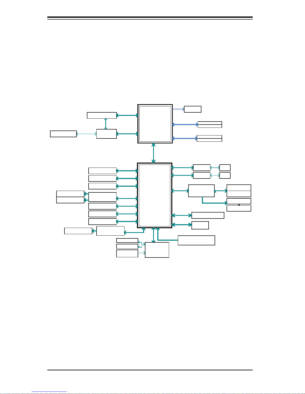
Figure 1-1. Intel P67 Chipset:
System Block Diagram
Note: This is a general block diagram. Please see Chapter 5 for details.
SVID
VRM 12
4 UDIMM
DDR3 (CH1)
1333/1066MHz
DDR3 (CH2)
1333/1066MHz
DIMM1B
DIMM1A (Blue)
DIMM2B
DIMM2A (Blue)
PCIe x8 SLOT #4
PCIe x16 SLOT #6
PCIe2.0_x8
5.0GT/s
PCIe2.0_x8
5.0GT/s
AS Media
Switch
ASM1440
PCIe2.0_x8
5.0GT/s
PCIe2.0_x8
5.0GT/s
INTEL LGA1155
(Socket-H2)
VRD12
x4 DMI
5GT/s
1 PATA PORT
2 SATA-III PORTS
2 USB3.0 PORTS
PCIe x1 SLOT #3
PCIe x1 SLOT #5
PCIe x1 SLOT #7
Marvell 88SE9128
2 SATA-III PORTS
4 SATA-II PORTS
14 USB PORTS
NEC uPD720200
PCIe2.0_x1
5.0GT/s
PCIe2.0_x1
5.0GT/s
PCIe2.0_x1
5.0GT/s
PCIe2.0_x1
5.0GT/s
SATA-III
600MB/s
SATA-II
300MB/s
USB2.0
480Mbps
PCIe2.0_x1
5.0GT/s
COM1/2
P/S2 KB/MS
HEALTH
INFO
Intel
P67
PCH
LPC
NCT6776F
LPC I/O
AZALIA BUS
PCIe2.0_x1
5.0GT/s
PCIe2.0_x1
5.0GT/s
PCIe_x1
5.0GT/s
PCI-E to PCI
Bridge
IDT 89HPEB383
LPC
SPI
ALC889-GR
7.1ch HD Audio codec
GLAN1
RTL8111E
GLAN2
RTL8111E
PCI32
PCI32
TPM1.2 Pin Header
FLASH
SPI 32Mb
RJ45
RJ45
PCI32 SLOT #1
PCI32 SLOT #2
TI 1394a
2 1394a PORTS
1-4
Page 13

Chapter 1: Introduction
1-4 Contacting Supermicro
Headquarters
Address: Super Micro Computer, Inc.
980 Rock Ave.
San Jose, CA 95131 U.S.A.
Tel: +1 (408) 503-8000
Fax: +1 (408) 503-8008
Email: marketing@supermicro.com (General Information)
support@supermicro.com (Technical Support)
Web Site: www.supermicro.com
Europe
Address: Super Micro Computer B.V.
Het Sterrenbeeld 28, 5215 ML
's-Hertogenbosch, The Netherlands
Tel: +31 (0) 73-6400390
Fax: +31 (0) 73-6416525
Email: sales@supermicro.nl (General Information)
support@supermicro.nl (Technical Support)
rma@supermicro.nl (Customer Support)
Asia-Pacifi c
Address: Super Micro Computer, Inc.
4F, No. 232-1, Liancheng Rd.
Chung-Ho 235, Taipei County
Taiwan, R.O.C.
Tel: +886-(2) 8226-3990
Fax: +886-(2) 8226-3991
Web Site: www.supermicro.com.tw
Technical Support:
Email: support@supermicro.com.tw
Tel: 886-2-8228-5990
1-5
Page 14

SuperWorkstation 5037A-T User's Manual
Notes
1-6
Page 15
Chapter 2: Installation
!
!
Chapter 2
Installation
2-1 Overview
This chapter provides a quick setup checklist to get your SuperWorkstation 5037A-T
up and running. Following these steps in the order given should enable you to have
the system operational within a minimum amount of time. This quick setup assumes
that your system has come to you with the processor and memory preinstalled. If
your system is not already fully integrated with a serverboard, processor, system
memory etc., please turn to the chapter or section noted in each step for details on
installing specifi c components.
2-2 Unpacking the System
You should inspect the box the system was shipped in and note if it was damaged
in any way. If the system itself shows damage you should fi le a damage claim with
the carrier who delivered it.
Decide on a suitable location for the SuperWorkstation. It should be situated in
a clean, dust-free area that is well ventilated. Avoid areas where heat, electrical
noise and electromagnetic fi elds are generated. You will also need it placed near
a grounded power outlet. Be sure to read the Rack and Server Precautions in the
next section.
Warnings and Precautions!
• Ensure that the caster wheels on the workstation are locked.
• Review the electrical and general safety precautions in Chapter 4.
• Use a regulating uninterruptible power supply (UPS) to protect the workstation
from power surges, voltage spikes and to keep your system operating in case
of a power failure.
• Allow the power supply units and hot-swap SATA drives to cool before touch-
ing them.
2-1
Page 16
SuperWorkstation 5037A-T User's Manual
• To maintain proper cooling, always keep all chassis panels closed and all SATA
carriers installed when not being serviced.
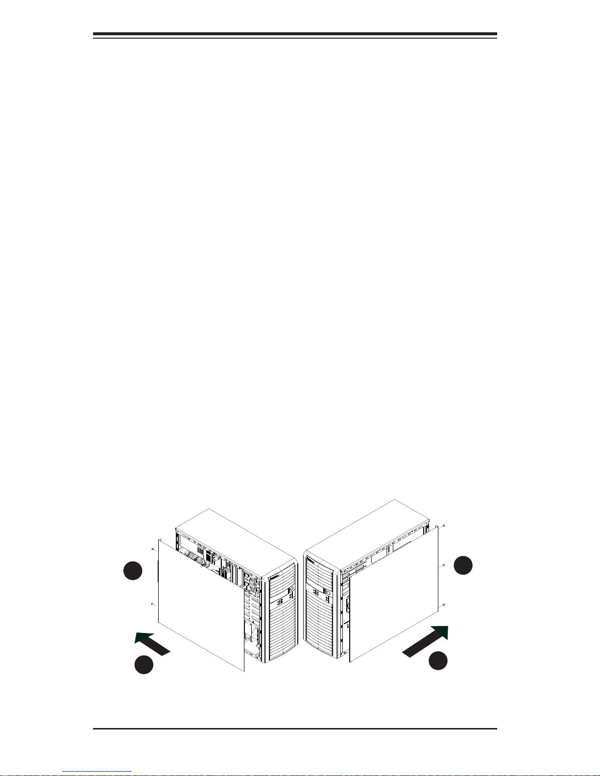
2-3 Accessing the Inside of the System
You may need to access the system periodically to perform maintenance or install
components such as hard drives. The SC732 features two removable side covers,
allowing easy access to the chassis interior.
Removing the Side Covers
1. Disconnect the chassis from any power souce.
2. Remove the two screws securing the left side cover to the chassis.
3. Slide the left cover toward the rear of the chassis.
4. Lift the left cover from the chassis.
5. Remove the three screws securing the right side cover to the chassis.
6. Slide the right cover toward the rear of the chassis
7. Lift the right cover from the chassis.
Figure 2-1. Removing the Chassis Side Covers
2
2
1
5
1
3
2-2
1
6
Page 17

Chapter 3: System Interface
Chapter 3
System Interface
3-1 Overview
The control panel on the 5037A-T has several LEDs and a power button. There are
also two LEDs on each hard drive carrier. These LEDs keep you constantly informed
of the overall status of the system and the activity and health of specifi c components.
3-2 Control Panel Button
A single push-button is located on the front of the chassis.
Power
This is the main power button, which is used to apply or turn off the main system
power. T urning off system power with this button removes the main power but keeps
standby power supplied to the system.
3-3 Communications Panel Components
The SC732D2 features a front communication panel allowing easy access to the
chassis communication ports. The chassis models are equipped as follows:
• Two USB 2.0 ports
• Audio port
• Mic port
See diagram on the following page.
3-1
Page 18
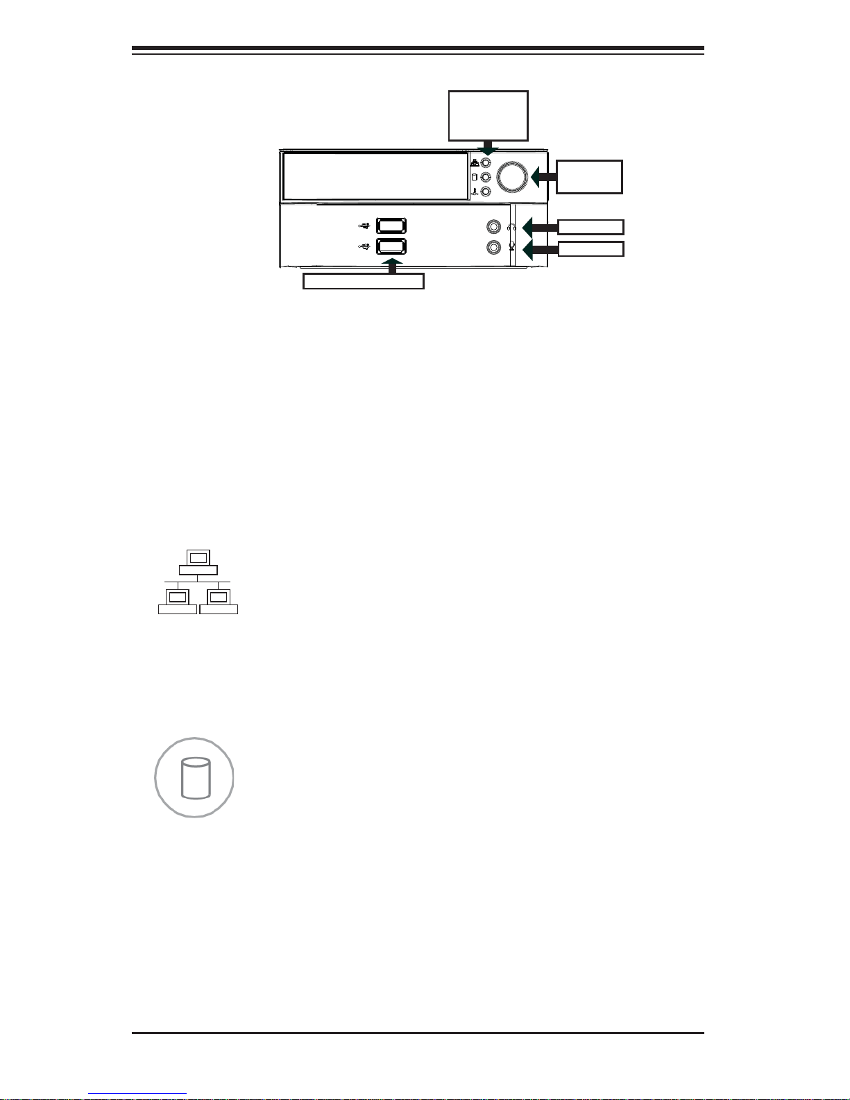
SuperWorkstation 5037A-T User's Manual
NIC LED
HDD LED
OH LED
Power
Button
Audio
Mic
2x USB2.0
3-4 Control Panel LEDs
The control panel located on the front of the SC732 chassis has three LEDs. These
LEDs provide you with critical information related to different parts of the system.
This section explains what each LED indicates when illuminated and any corrective
action you may need to take.
NIC
Indicates network activity on the LAN port(s) when fl ashing.
HDD
Indicates IDE channel activity on the SATA drive, and/or DVD-ROM drive activity
when fl ashing.
3-2
Page 19

Chapter 3: System Interface
Overheat/Fan Fail
When this LED fl ashes, it indicates a chassis fan failure. When on continuously it
indicates an overheat condition, which may be caused by cables obstructing the
airfl ow in the system or the ambient room temperature being too warm. Check the
routing of the cables and make sure all fans are present and operating normally.
You should also check to make sure that the chassis covers are installed. Finally,
verify that the heatsinks are installed properly (see Chapter 5). This LED will remain
fl ashing or on as long as the indicated condition exists.
3-4 Drive Carrier LEDs
Note: the LEDs of some drive carriers may not function depending on the number
of drives that are supported by the serverboard and/or backplane.
• Green: When illuminated, the green LED on the front of the hard drive carrier
indicates drive activity. A connection to the drive backplane enables this LED to
blink on and off when that particular drive is being accessed.
• Red: The backplane activates the red LED to indicate a drive failure. If one of
the hard drives fail, you should be notifi ed by your system management soft-
ware. Please refer to Chapter 6 for instructions on replacing failed hard drives.
3-3
Page 20

SuperWorkstation 5037A-T User's Manual
Notes
3-4
Page 21
Chapter 4: System Safety
!
Chapter 4
System Safety
4-1 Electrical Safety Precautions
Basic electrical safety precautions should be followed to protect yourself from
harm and the SuperWorkstation 5037A-T from damage:
• Be aware of the locations of the power on/off switch on the chassis as well
as the room's emergency power-off switch, disconnection switch or electrical
outlet. If an electrical accident occurs, you can then quickly remove power from
the system.
• Do not work alone when working with high voltage components.
• Power should always be disconnected from the system when removing or in-
stalling main system components, such as the serverboard, memory modules
and the DVD-ROM and fl oppy drives. When disconnecting power, you should
fi rst power down the system with the operating system. The unit has more than
one power supply cord. Disconnect both power supply cords before servicing
to avoid electrical shock.
• When working around exposed electrical circuits, another person who is familiar
with the power-off controls should be nearby to switch off the power if necessary.
• Use only one hand when working with powered-on electrical equipment. This
is to avoid making a complete circuit, which will cause electrical shock. Use
extreme caution when using metal tools, which can easily damage any electrical
components or circuit boards they come into contact with.
• Do not use mats designed to decrease electrostatic discharge as protection from
electrical shock. Instead, use rubber mats that have been specifi cally designed
as electrical insulators.
• The power supply power cord must include a grounding plug and must be
plugged into grounded electrical outlets.
4-1
Page 22
SuperWorkstation 5037A-T User's Manual
!
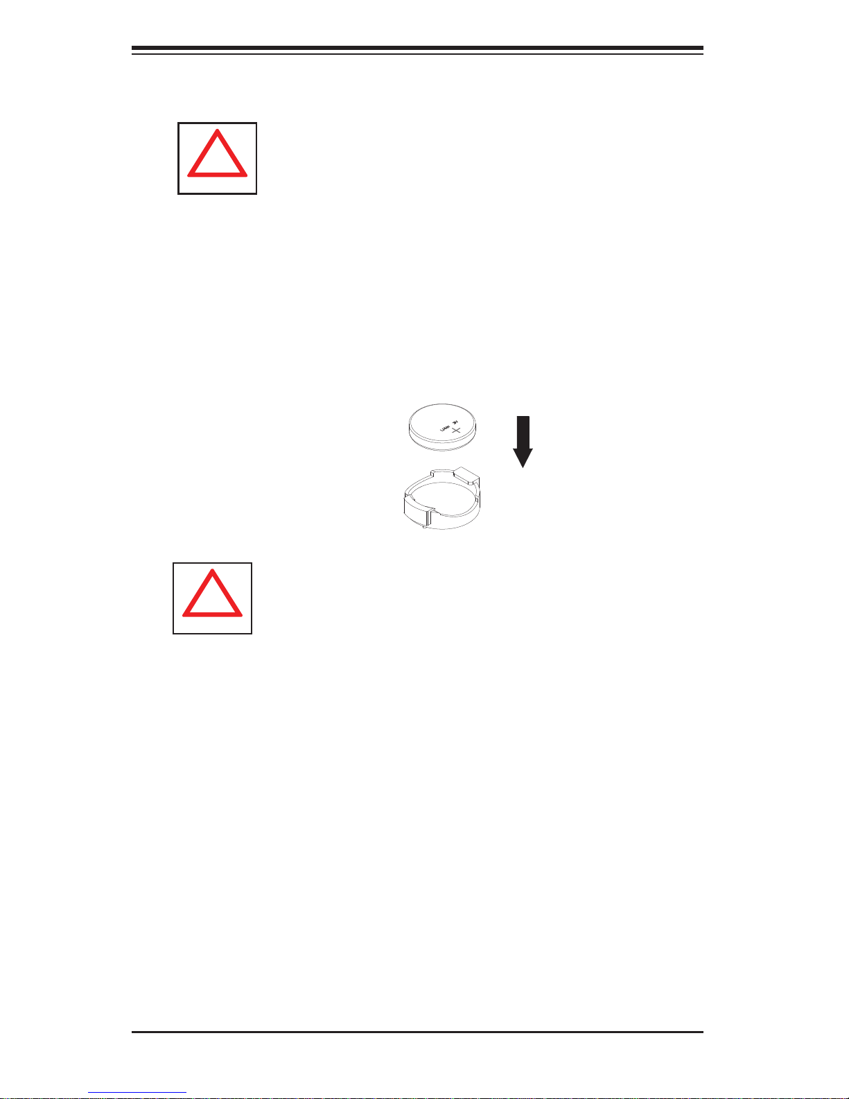
• Serverboard Battery: CAUTION - There is a danger of explosion if the onboard
battery is installed upside down, which will reverse its polarities (see Figure 4-1).
This battery must be replaced only with the same or an equivalent type recommended by the manufacturer (CR2032). Dispose of used batteries according to
the manufacturer's instructions.
• DVD-ROM Laser: CAUTION - this server may have come equipped with a
DVD-ROM drive. To prevent direct exposure to the laser beam and hazardous
radiation exposure, do not open the enclosure or use the unit in any unconventional way.
• Mainboard replaceable soldered-in fuses: Self-resetting PTC (Positive Tempera-
ture Coeffi cient) fuses on the mainboard must be replaced by trained service
technicians only. The new fuse must be the same or equivalent as the one
replaced. Contact technical support for details and support.
4-2 General Safety Precautions
Follow these rules to ensure general safety:
• Keep the area around the SuperWorkstation 5037A-T clean and free of clutter.
• The 5037A-T weighs approximately 39 lbs (17.7 kg.) when fully loaded. When
lifting the system, two people at either end should lift slowly with their feet spread
out to distribute the weight. Always keep your back straight and lift with your
legs. Don't use the handles (if installed) to lift the chassis; the handles should
only be used to pull the server out of the rack.
• Place the chassis top cover and any system components that have been re-
moved away from the system or on a table so that they won't accidentally be
stepped on.
• While working on the system, do not wear loose clothing such as neckties and
unbuttoned shirt sleeves, which can come into contact with electrical circuits or
be pulled into a cooling fan.
• Remove any jewelry or metal objects from your body, which are excellent metal
conductors that can create short circuits and harm you if they come into contact
with printed circuit boards or areas where power is present.
4-2
Page 23
Chapter 4: System Safety
!
• After accessing the inside of the system, close the system back up and secure
it to the rack unit with the retention screws after ensuring that all connections
have been made.
4-3 ESD Precautions
Electrostatic discharge (ESD) is generated by two objects with different electrical
charges coming into contact with each other. An electrical discharge is created to
neutralize this difference, which can damage electronic com ponents and printed
circuit boards. The following measures are generally suffi cient to neutralize this
difference before contact is made to protect your equipment from ESD:
• Use a grounded wrist strap designed to prevent static discharge.
• Keep all components and printed circuit boards (PCBs) in their antistatic bags
until ready for use.
• Touch a grounded metal object before removing the board from the antistatic
bag.
• Do not let components or PCBs come into contact with your clothing, which may
retain a charge even if you are wearing a wrist strap.
• Handle a board by its edges only; do not touch its components, peripheral chips,
memory modules or contacts.
• When handling chips or modules, avoid touching their pins.
• Put the serverboard and peripherals back into their antistatic bags when not
in use.
• For grounding purposes, make sure your computer chassis provides excellent
conductivity between the power supply, the case, the mounting fasteners and
the serverboard.
4-3
Page 24
SuperWorkstation 5037A-T User's Manual
!
!
4-4 Operating Precautions
Care must be taken to assure that the chassis cover is in place when the system
is operating to assure proper cooling. Out of warranty damage to the system can
occur if this practice is not strictly followed.
Figure 4-1. Installing the Onboard Battery
LITHIUM BATTERY
BATTERY HOLDER
Please handle used batteries carefully. Do not damage the battery in any way; a
damaged battery may release hazardous materials into the environment. Do not
discard a used battery in the garbage or a public landfi ll. Please comply with the
regulations set up by your local hazardous waste management agency to dispose
of your used battery properly.
4-4
Page 25

Chapter 5: Advanced Motherboard Setup
Chapter 5
Advanced Motherboard Setup
This chapter covers the steps required to connect the C7P67 data and power
cables and install add-on cards. All motherboard jumpers and connections are
also described. A layout and quick reference chart are included in this chapter for
your reference. Remember to completely close the chassis when you have fi nished
working with the motherboard to better cool and protect the system.
5-1 Handling the Motherboard
Electrostatic discharge (ESD) can damage electronic com ponents. To prevent damage to any printed circuit boards (PCBs), it is important to handle them very carefully
(see previous chapter). To prevent the motherboard from bending, keep one hand
under the center of the board to support it when handling. The following measures
are generally suffi cient to protect your equipment from electric static discharge.
Precautions
• Use a grounded wrist strap designed to prevent Electrostatic Discharge.
• Touch a grounded metal object before removing boards from their antistatic bag.
• Handle a board by its edges only; do not touch its components, peripheral chips,
memory modules or gold contacts.
• When handling chips or modules, avoid touching their pins.
• Put the motherboard, add-on cards and peripherals back into their antistatic
bags when not in use.
• For grounding purposes, make sure your computer chassis provides excellent
conductivity between the power supply, the case, the mounting fasteners and
the motherboard.
Unpacking
The motherboard is shipped in antistatic packaging to avoid electrical static
discharge. When unpacking the board, make sure the person handling it is static
protected.
5-1
Page 26

SuperWorkstation 5037A-T User's Manual
5-2 Connecting Cables
Now that the motherboard is installed, the next step is to connect the cables to
the board. These include the data (ribbon) cables for the peripherals and control
panel and the power cables.
Connecting Data Cables
The cables used to transfer data from the peripheral devices have been carefully
routed to prevent them from blocking the fl ow of cooling air that moves through
the system from front to back. If you need to disconnect any of these cables, you
should take care to keep them routed as they were originally after reconnecting
them (make sure the red wires connect to the pin 1 locations). The following data
cables (with their locations noted) should be connected. (See the layout on page
5-9 for connector locations.)
• SATA drive data cable (I-SATA0 ~ I-SATA5)
• Control Panel cable (JF1)
Important! Make sure the the cables do not come into contact with the fans.
Connecting Power Cables
The C7P67 has a 24-pin primary power supply connector (JPW1) for connection
to the ATX power supply. In addition, an 8-pin processor power connector (JPW2)
must also be connected to your power supply. See Section 5-8 for power connector pin defi nitions.
Connecting the Control Panel
JF1 contains header pins for various front control panel connectors. See Figure 5-1
for the pin locations of the various front control panel buttons and LED indicators.
All JF1 wires have been bundled into a single ribbon cable to simplify this connection. Make sure the red wire plugs into pin 1 as marked on the board. The other
end connects to the Control Panel PCB board, located just behind the system status
LEDs on the chassis. See Section 5-8 for details and pin descriptions.
5-2
Page 27
Chapter 5: Advanced Motherboard Setup
Figure 5-1. Control Panel Header Pins
1
LED_Anode+
LED_Anode+
LED_Anode+
LED_Anode+
LED_Anode+
X
Reset
PWR
Reset Button
Power Button
Power LED
HDD LED
NIC1 LED
NIC2 LED
OH/Fan Fail LED
X
Ground
Ground
2
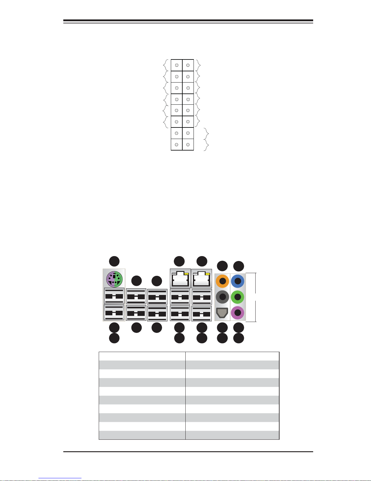
5-3 I/O Ports
The I/O ports are color coded in conformance with the PC 99 specifi cation. See
Figure 5-2 below for the colors and locations of the various I/O ports.
Figure 5-2. I/O Ports
3
5
2
4
7
6
1
1. USB 2.0 Port 8 11. USB 2.0 Port 0
2. USB 2.0 Port 9 12. USB 2.0 Port 1
3. Keyboard/Mouse Port 13. LAN2
4. USB 2.0 Port 13 14. SPDIF Out
5. USB 2.0 Port 10 15.Surround Out
6. USB 2.0 Port 11 16. CEN/LFE Out
7. USB 2.0 Port 12 17. Microphone In
8. USB 3.0 Port 0 18. Line Out
9. USB 3.0 Port 1 19. Line In
10. LAN 1
10
9
8
13
12
11
16
15
14
19
HD Audio
18
17
5-3
Page 28
SuperWorkstation 5037A-T User's Manual
5-4 Processor and Heatsink Installation
Notes:
• Always connect the power cord last and always remove it before adding, re-
moving or changing any hardware components. Make sure that you install the
processor into the CPU socket before you install the CPU heatsink.
• If you buy a CPU separately, make sure that you use an Intel-certifi ed multi-
directional heatsink only.
• Make sure to install the serverboard into the chassis before you install the CPU
heatsinks.
• When receiving a serverboard without a processor pre-installed, make sure that
the plastic CPU socket cap is in place and none of the socket pins are bent;
otherwise, contact your retailer immediately.
• Refer to the Sup ermi cro web s ite for upd ates on CPU su ppor t.
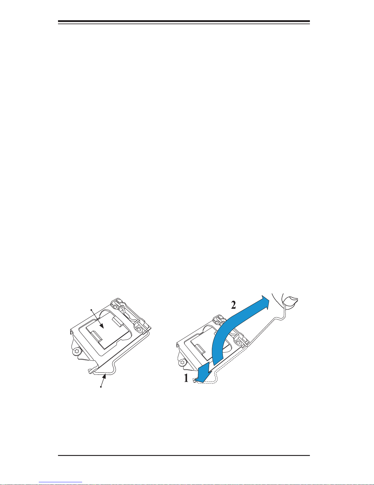
Installing the LGA1155 Processor
1. Press the load lever to release the load plate, which covers the CPU socket,
from its locked position.
2. Gently li ft t he load l ever to open t he load p late. Remove th e plate cap.
Load Plate
Load Lever
5-4
Page 29
Chapter 5: Advanced Motherboard Setup
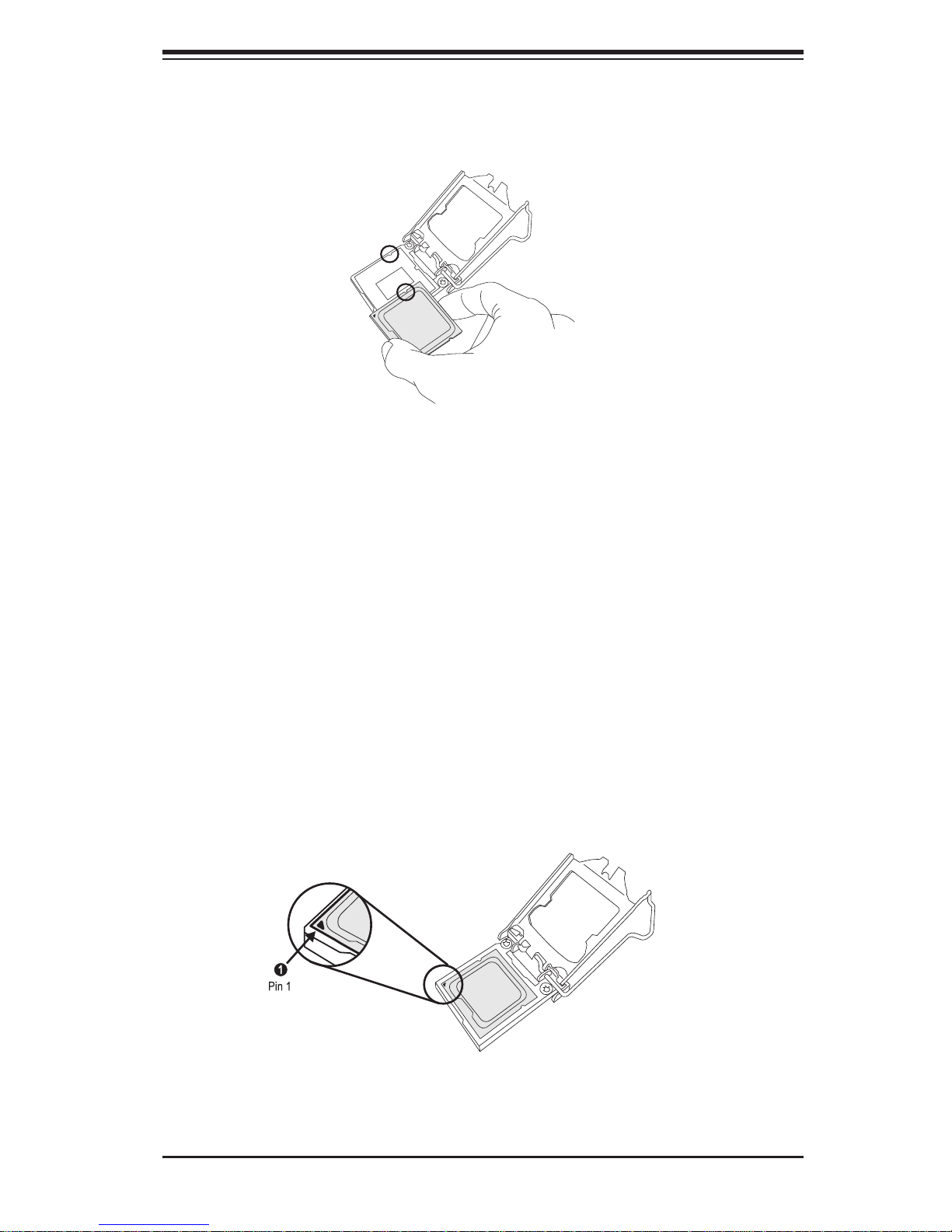
3. Use your thumb and your index fi nger to hold the CPU at the top center edge
and the bottom center edge of the CPU.
4. Align the CPU key (the semi-circle cutouts) against the socket keys. Once
aligned, carefully lower the CPU straight down to the socket. (Do not drop the
CPU on the socket. Do not move the CPU horizontally or vertically.
Do not rub the CPU against the surface or against any pins of the socket to
avoid damage to the CPU or the socket.)
With the CPU inside the socket, inspect the four corners of the CPU to make
sure that the CPU is properly installed.
5. Use your thumb to gently push the load lever down to the lever lock.
Save the plastic PnP cap. The motherboard must be shipped with the PnP
cap properly installed to protect the CPU socket pins. Shipment without the
PnP cap properly installed will cause damage to the socket pins.
5-5
Page 30

SuperWorkstation 5037A-T User's Manual
!
CPU properly
installed
B
A
Make sure "A"
points are under B
Warning: The CPU will only seat inside the socket in one direction. Make
sure it is properly inserted before closing the load plate. If it doesn't close
properly, do not force it as it may damage your CPU. Instead, open the load
plate again and double-check that the CPU is aligned properly.
Load lever locked
into place.
5-6
Page 31

!
Installing an Active Fan
!
CPU Heatsink
1. Locate the CPU Fan power connec-
tor on the motherboard. (Refer to
the layout on the right for the CPU
Fan location.)
2. Position the heatsink so that the
heatsink fan wires are closest to the
CPU fan power connector and are
not interfered with other components.
3. Inspect the CPU Fan wires to make
sure that the wires are routed
through the bottom of the heatsink.
Chapter 5: Advanced Motherboard Setup
Thermal Grease
4. Remove the thin layer of the protec-
tive fi lm from the copper core of the
heatsink.
Warning: CPU may overheat
if the protective fi lm is not re-
moved from the heatsink.
5. Apply the proper amount of thermal
grease on the CPU.
Note: if your heatsink came with
a thermal pad, please ignore
this step.
6. If necessary, rearrange the wires
to make sure that the wires are not
pinched between the heatsink and
the CPU. Also make sure to keep
clearance between the fan wires
and the fi ns of the heatsink.
Heatsink
Fins
Warning: We do not recommend removing the CPU or the heatsink.
However, if you do need to uninstall the heatsink, please follow these
instructions to avoid damaging the CPU or the CPU socket.
5-7
Page 32

SuperWorkstation 5037A-T User's Manual
7. Align the four heatsink fasteners with the mounting holes
on the motherboard. Gently
push the pairs of diagonal
fasteners (#1 & #2, and #3 &
#4) into the mounting holes
until you hear a click. Also,
make sure to orient each
fastener so that the narrow
end of the groove is pointing
outward.
8. Repeat Step 7 to insert all
four heatsink fasteners into
the mounting holes.
9. Once all four fasteners are
securely inserted into the
mounting holes, and the
heatsink is properly installed
on the motherboard, connect
the heatsink fan wires to the
CPU Fan connector.
5-8
Page 33

Removing the Heatsink
Warning: We do not recommend
that the CPU or the heatsink be
removed. However, if you do
need to remove the heatsink,
please follow the instructions below to remove the heatsink and to
prevent damage done to the CPU
or other components.
Active Heatsink Removal
Chapter 5: Advanced Motherboard Setup
1. Unplug the power cord from the
power supply.
2. Disconnect the heatsink fan wires
from the CPU fan header.
3. Use your fi nger tips to gently press
on the fastener cap and turn it
counterclockwise to make a 1/4 (90
0
)
turn, and pull the fastener upward to
loosen it.
4. Repeat Step 3 to loosen all fasteners
from the mounting holes.
5. With all fasteners loosened, remove
the heatsink from the CPU.
Unplug the
PWR cord
Pull Up
5-9
Page 34

SuperWorkstation 5037A-T User's Manual
5-5 Installing Memory Modules
Note: Check the S uper micro we b site for r ecom mende d memor y mo dules .
CAUTION
Exercise extreme care when installing or removing DIMM
module s to prevent a ny possi ble dam age.
Installing & Removing DIMMs
1. Insert the desired number of DIMMs into the memory slots, starting with
DIMM #1A. For best performance, please use the memory modules of the
same type and speed in the same bank. See the DIMM Installation Chart on
the following page.
2. Press down the release tabs on the ends of a memory slot. Insert each DIMM
module vertically into its slot. Pay attention to the notch along the bottom of
the module to prevent inserting the DIMM module incorrectly.
3. Gently press down on the DIMM module until it snaps into place in the slot.
Repeat for all modules.
4. Reverse the steps above to remove the DIMM modules from the motherboard.
Figure 5-3. DIMM Installation
Notch
To Ins tall : Inser t module
vert ic ally a nd pre ss
down unt il it sn aps in to
place. Pay a tte ntio n to
the ali gnme nt notc h at
the bottom.
Front View
Notch
To Remove:
Use your thumbs to
gently push the release
tabs near both ends of
the module. This should
release it from the slot.
Release Tab
Note: Notch should align
with the receptive key
point on the slot.
Top View of DDR3 Slot
5-10
Release Tab
Page 35

Chapter 5: Advanced Motherboard Setup
Memory Support
The C7P67 supports up to 32GB of Unbuffered (UDIMM) DDR3 Non-ECC
1333/1066 M Hz in 4 memor y slots. Po pulating th ese DIMM m odules wit h a pair
of memory modules of the same type and same size will result in interleaved
memory, which will improve memory performance. Please refer to the table below:
DIMM 1B
DIMM 1B (Channel 1, Slot B) (Black)
DIMM 1A
(Blue)
DIMM 1A (Channel 1, Slot A) (Blue)
DIMM 2B (Channel 2, Slot B) (Black)
DIMM 2B
DIMM 2A
(Blue)
DIMM 2A (Channel 2, Slot A) (Blue)
Memory Population Guidelines
Please follow the table below when populating the C7P67.
DDR3 Unbuffered Non-ECC (UDIMM) Memory
DIMM Slots per
Channel
2 1 Unbuffered
2 2 Unbuffered
Notes
DIMMs Populated
per Channel
DIMM Type POR Speeds Ranks per DIMM (any
1066, 1333 Single Rank, Dual Rank
DDR3
1066, 1333 Single Rank, Dual Rank
DDR3
combination)
• Due to mem or y alloc ation t o system devi ces, th e amount of m emor y that
remains ava ilabl e for op erati onal use w ill be r educ ed when 4 G B of R A M
is used. T he reductio n in memor y availability i s dispropor tional. S ee the
follow ing tab le for det ails.
• For Microsoft Windows users: Microsoft implemented a design change in the
Windows XP with Service Pack 2 (SP2) and Windows Vista. This change is
specifi c to the behavior of Physical Address Extension (PAE) mode which
improves driver compatibility . For more information, please read the following
article at Microsoft’s Knowledge Base website at: http://support.microsoft.
com/kb/888137.
5-11
Page 36

SuperWorkstation 5037A-T User's Manual
Possible System Memory Allocation & Availability
System Device Size Physical Memory
Firmware Hub fl ash memory (System BIOS) 1 MB 3.99
Local APIC 4 KB 3.99
Area Reserved for the chipset 2 MB 3.99
I/O APIC (4 Kbytes) 4 KB 3.99
PCI Enumeration Area 1 256 MB 3.76
PCI Express (256 MB) 256 MB 3.51
PCI Enumeration Area 2 (if needed) -Aligned on 256-MB
boundaryTSEG 1 MB 2.84
Memory available to OS and other applications 2.84
512 MB 3.01
Remaining (-Available)
(4 GB Total System
Memory)
5-6 Adding PCI Add-On Cards
The 5037A-T can accommodate standard size add-on cards populated in all slots
on the C7P67 motherboard.
Installing an Add-on Card
1. Begin by removing the PCI slot shield for the slot you wish to populate.
2. Fully seat the card into the riser card slot, pushing down with your thumbs
evenly on both sides of the card.
3. Finish by using a screw to secure the top of the card shield to the chassis.
The PCI slot shields protect the motherboard and its components from EMI
and aid in proper ventilation, so make sure there is always a shield covering
each unused slot.
5-12
Page 37

5-7 Motherboard Details
Figure 5-4. C7P67 Layout
Chapter 5: Advanced Motherboard Setup
JHD_ACI
1394a 2
1394a 1
JI2C2
JI2C1
Slot1
JTPM1
Slot2
JPI1
USB2/3
Battery
USB4/5
JBT1
JWF1
IDE
COM2
Audio FP
JHD_AC1
J18
J15
JTPM1
1
USB4/5
SPIDF-Out
AUDIO FP
1394_2
Slot1 PCI 33MHZ
1394_1
JI2C2
JI2C1
USB2/3
IDE
JWF1
Marvel
SATA 3 CTRL
COM2
SPIDF-In
JSPDIF_OUT
JSPDIF_IN
1394
CTRL
I-SATA5 I-SATA2
M-SATA0
SATA 3.0
COM1
COM1
JPAC1
Audio CTRL
JPAC1
Slot2 PCI 33MHZ
I-SATA3
I-SATA4
I-SATA1
I-SATA0
M-SATA1
JWOR
JWOR
Slot4 Slot5 Slot6
Slot3
JPL2
Slot3 PCI-E 2.0 X1
Slot4 PCI-E 2.0 X8 (INX16)
PCI
CTRL
JPI1
JBT1
Battery
B1
I-SATA3~5
I-SATA0~2
M-SATA0/1
S I/O
JL1
JL1
JWOL
JWOL Fan AJD1
JPME1
JPME1
LAN CTRL
Slot5 PCI-E 2.0 X1
Intel
P67 PCH
BIOS
JPL1JPL2
JPL1
FANA
Slot7
LAN CTRL
Slot7 PCI-E 2.0 X1
Slot6 PCI-E 2.0 X16
Buzzer
SP1
JD1
Buzzer
HD Audio
Fan4
HD AUDIO
FAN4
Always Populate Blue Sockets First
LED1
LED1
JLED
1
FP CTRL
FP CTRL
JF1
FAN3
Fan 3
LAN 2
USB2.0 0/1
LAN2
USB 2.0 0/1
JLED
LAN 1
USB3.0 0/1
LGA1155
DIMM1B
DIMM1A
DIMM2B
DIMM2A
JPW1
USB11/12
LAN1
USB11/12
USB3.0 0/1
USB 3.0 CTRL
C7P67
Rev. 1.01
CPU
Unbuf. Non-ECC DDR3 DIMM Required
USB10/13
USB13/10
CATERR_LED1
JITP1
JPW1 Fan2
KB/Mouse
USB8/9
KB/Mouse
USB8/9
JPW2
JCPUVRD_SMB
FAN2
JPW2
FAN1
Fan1
DIMM1B
DIMM1A
DIMM2B
DIMM2A
Jumper Description Default
JBT1 CMOS Clear (See Section 5-9)
JHD_AC1 High Defi nition Front Panel Audio/AC 97' FP Audio Select (See Section 5-9)
2
JI
C1/JI2C2 SMB to PCI Slots Off (Enabled)
JPAC1 Audio Enable Pins 1-2 (Enabled)
JPI1 IEEE 1394 Enable Pins 1-2 (Enabled)
JPL1/JPL2 LAN1/LAN2 Enable Pins 1-2 (Enabled)
JPME1 Intel ME Mode Select Off (Normal)
C7P67 Jumpers
5-13
Page 38

SuperWorkstation 5037A-T User's Manual
C7P67 Headers/Connectors
Connector Description
Audio_FP Front Panel Audio Header
HD Audio High-Defi nition Audio Connector
B1 Onboard Battery
COM1/COM2 COM1/2 Serial Connection Headers
BIOS AMI SPI BIOS
Fans 1~4, Fan A System/CPU Fan Headers (Fan1: CPU Fan)
J15/J18 IEEE 1394_1 (J15)/1394_2 (J18) Headers
JCPUVRD SMB PWM SMB programming header (for debugging only)
IDE IDE Connector Header
JD1 Speaker/buzzer (Pins 1-2: Buzzer, Pins 1~4: External Speaker)
JF1 Front Panel Control Header
JL1 Chassis Intrusion Header
JLED Power LED Indicator Header
JPW1 24-pin ATX Main Power Connector (Required)
JPW2 +12V 8-pin CPU power Connector (Required)
KB/Mouse Keyboard/Mouse Connectors
LAN1/LAN2 Gigabit (RJ45) Ports (LAN1/2)
JSPDIF_In/JSPDIF_OUT SPDIF_(Sony/Philips Digital Interface)_In/ SPDIF_Out Headers
JTPM1 Trusted Platform Module (TPM)/80 Port Header
JWF1 SATA DOM (Device_On_Module) Power Connector
JWOL Wake_On_LAN Header
JWOR Wake_On-Ring Header
Slot1/Slot2 PCI 33 MHz Slots
Slot3/Slot5/Slot7 PCI-Express 2.0 x1 Slots
Slot4 PCI-Express 2.0 x8 in x16 Slot
Slot6 PCI-Express 2.0 x16 Slot
(I-)SATA (3.0) 0/1, (2.0) 2~5 (Intel) Serial ATA 3.0 Ports 0/1. Serial ATA 2.0 2~5
(M-)SATA (3.0) 0/1 (Marvel) Serial ATA 3.0 Ports 0/1
USB (2.0) 0/1, 8/9, 11/12, 13/10 Backpa nel US B 2.0 Por ts 0 /1, 8/9, 11/12, 13/10
USB (3.0) 0/1 Backpa nel US B 3.0 Por t s 0/1
USB2/ 3, USB 4/ 5 Front Acc essib le USB C onne cti ons 2 /3, 4/ 5
LED Description Color/State Status
LED1 Onboar d Sta ndby PW R LED Green: Solid on Power On
C7P67 LED Indicators
5-14
Page 39

Chapter 5: Advanced Motherboard Setup
5-8 Connector Defi nitions
Main ATX Power Supply
Connector
The 24-pin main power connector
(JPW1) is used to provide power to
the motherboard. The 8-pin CPU
PWR connector (JPW2) is also
required for the processor. These
power co nnec tor s mee t the SS I EPS
12V spe ci fi cat ion. See the t ables on
the ri ght for pi n defi nitions.
ATX Power 24-pin Connector
Pin Defi nitions (JPW1)
Pin# Defi nition Pin # Defi nition
13 +3.3V 1 +3.3V
14 -12V 2 +3.3V
15 COM 3 COM
16 PS_ON 4 +5V
17 COM 5 COM
18 COM 6 +5V
19 COM 7 COM
20 Res (NC) 8 PWR_OK
21 +5V 9 5VSB
22 +5V 10 +12V
23 +5V 11 +12V
24 COM 12 +3.3V
12V 8-pin Processor Power
Pin Defi nitions (JPW2)
Pins Defi nition
1 - 4 Ground
5 - 8 +12V
Required Connection
Power LED
The Power LED connection is located
on pins 15 and 16 of JF1. Refer to the
table on the right for pin defi nitions.
HDD LED
The HDD LED connection is located
on pins 13 and 14 of JF1. Attach a
cable here to indicate the status of
HDD-related activities, including IDE,
SATA activities. See the table on the
right for pin defi nitions.
5-15
Power LED
Pin Defi nitions (JF1)
Pin# Defi nition
15 +5V
16 Ground
HDD LED
Pin Defi nitions (JF1)
Pin# Defi nition
13 +5V
14 HD Active
Page 40

SuperWorkstation 5037A-T User's Manual
NIC1/NIC2 (LAN1/LAN2)
The NIC (Network Interface Controller) LED connection for LAN port 1
is located on pins 11 and 12 of JF1,
and the LED connection for LAN Port
2 is on Pins 9 and 10. NIC1 LED and
NIC2 LED are 2-pin NIC LED headers.
Attach NIC LED cables to NIC1 and
NIC2 LED indicators to display network
activities. Refer to the table on the right
for pin defi nitions.
Overheat (OH)/Fan Fail
Connect an LED cable to OH/Fan Fail
connections on pins 7 and 8 of JF1 to
provide warnings for chassis overheat/
fan failure. Refer to the table on the
right for pin defi nitions.
LAN1/LAN2 LED
Pin Defi nitions (JF1)
Pin# Defi nition
9/11 Vcc
10/12 Ground
OH/Fan Fail LED
Pin Defi nitions (JF1)
Pin# Defi nition
7 Vcc/Blue UID LED
8 OH/Fan Fail LED
OH/Fan Fail Indicator
Status
State Defi nition
Off Normal
On Overheat
Flash-
ing
Fan Fail
Reset Button
The Reset Button connection is located on pins 3 and 4 of JF1. Attach
it to a hardware reset switch on the
computer case to reset the system.
Refer to the table on the right for pin
defi nitions.
Power Button
The Power Button connection is located on pins1 and 2 of JF1. Momentarily
contacting both pins will power on/off
the system. This button can also be
confi gured to function as a suspend
button (with a setting in the BIOS - see
Chapter 4). To turn off the power in the
suspend mode, press the button for at
least 4 seconds. Refer to the table on
the right for pin defi nitions.
Reset Button
Pin Defi nitions (JF1)
Pin# Defi nition
3 Reset
4 Ground
Power Button
Pin Defi nitions (JF1)
Pin# Defi nition
1 Signal
2 +3V Standby
5-16
Page 41

Chapter 5: Advanced Motherboard Setup
Chassis Intrusion
A Chassis Intrusion header is located
at JL1 on the motherboard. Attach the
appropriate cable from the chassis to
inform you of a chassis intrusion when
the chassis is opened.
Fan Headers
The C7P67 has fi ve fan headers (Fan
1~Fan 4 and Fan A). These fans are
4-pin fan headers. However, Pins
1-3 of the fan headers are backward
compatible with the traditional 3-pin
fans (without fan speed control). A
fan speed control setting in the BIOS
Hardware Monitoring section allows
the BIOS to automatically set fan
speeds based on the system temperature. Refer to the table on the right for
pin defi nitions.
Chassis Intrusion
Pin Defi nitions (JL1)
Pin# Defi nition
1 Intrusion Input
2 Ground
Fan Header
Pin Defi nitions
Pin# Defi nition
1 Ground (Black)
2 2.5A/+12V
(Red)
3 Tachometer
4 PWM_Control
Note: Please use all 3-pin fans or all
4-pin fans on a motherboard. Please
do not use 3-pin fans and 4-pin fans
on the same board.
Internal Buzzer
The Internal Buzzer (SP1) can be
used to provide audible indications for
various beep codes. See the table on
the right for pin defi nitions.
Speaker
On the JD1 header, pins 3~4 are used
for internal speaker. Close pins 3~4
with a cap to use the onboard speaker.
If you wish to use an external speaker,
close Pins 1~4 with a cable. See the
table on the right for pin defi nitions.
Internal Buzzer
Pin Defi nition
Pin# Defi nitions
Pin 1 Pos. (+) Beep In
Pin 2 Neg. (-) Alarm
Speaker
Speaker Connector
Pin Defi nitions
Pin Setting Defi nition
Pins 3~4 Internal Speaker
Pins1~4 External Speaker
5-17
Page 42

SuperWorkstation 5037A-T User's Manual
IEEE Connection
1394a_1 (J15) and 1394a_2 (J18)
provide the IEEE 1394a connections
on the motherboard. See the tables
on the right for pin defi nitions.
1394_1
Pin Defi nitions
Pin# Defi ni-
tion
1 PTPA0+ 2 PTPA03 GND 4 GND
5 PTPB0+ 6 PTPB07 PWR
1394a
1394_2
Pin Defi nitions
Pin# Defi nition Defi nition
1 PTPA1+ 2 PTPA13 GND 4 GND
5 PTPB1+ 6 PTPB17 PWR
1394a
Defi nition
8 PWR
1394a
10 Shield
GND
8 PWR
1394a
10 Shield
GND
Serial Ports
Two COM connections (COM1 &
COM2) are located on the motherboard. COM1 is located close to
M-SATA ports 0/1. COM2 is located
next to the IDE drive to provide additional onboard serial connection
support. See the table on the right for
pin defi nitions.
TPM Header/Port 80
A Trusted Platform Module/Port 80
header is located at JTPM1 to provide
TPM support and Port 80 connection.
Use this header to enhance system
performance and data security. See
the table on the right for pin defi ni-
tions.
Serial Ports-COM1/COM2
Pin Defi nitions
Pin # Defi nition Pin # Defi nition
1 DCD 6 DSR
2 RXD 7 RTS
3 TXD 8 CTS
4 DTR 9 RI
5 Ground 10 N/A
TPM/Port 80 Header
Pin Defi nitions
Pin # Defi nition Pin # Defi nition
1 LCLK 2 GND
3 LFRAME# 4 <(KEY)>
5 LRESET# 6 +5V (X)
7 LAD 3 8 LAD 2
9 +3.3V 10 LAD1
11 LAD0 12 GND
13 SMB_CLK4 14 SMB_DAT4
15 +3V_DUAL 16 SERIRQ
17 GND 18 CLKRUN# (X)
19 LPCPD# 20 LDRQ# (X)
5-18
Page 43

DOM PWR Connector
The Disk-On-Module (DOM) power
connector, located at JWF1, provides
5V (Gen1/Gen) power to a solid_state
DOM storage device connected to one
of the SA T A ports. See the table on the
right for pin defi nitions.
Chapter 5: Advanced Motherboard Setup
DOM PWR
Pin Defi nitions
Pin# Defi nition
15V
2 Ground
3 Ground
Wake-On-LAN
The Wake-On-LAN header is located
at JWOL on the motherboard. See the
table on the right for pin defi nitions.
(You must also have a LAN card with
a Wake-On-LAN connector and cable
to use this feature.)
Wake-On-Ring
The Wake-On-Ring header is located
at JWOR. This function allows your
computer to wake up when receiving
an incoming call to the modem while
in the suspend state. See the table
on the right for pin defi nitions. Y ou
must have a Wake-On-Ring card and
a cable to use this feature.
Wake-On-LAN
Pin Defi nitions
(JWOL)
Pin# Defi nition
1 +5V Standby
2 Ground
3 Wake-up
Wake-On-Ring
Pin Defi nitions
Pin# Defi nition
1 Ground
2 Wake-up
SPDIF_In/SPDIF_Out Headers
The SPDIF_In (JSPDIF_In) and SPDIF_Out (JSPDIF_Out) are located
between PCI Slot1 and Slot2. Place
caps on these headers to use these
features. You will also need the
cables to use these features.
5-19
SPDIF_In
Pin Defi nitions
Pin# Defi nition
1 S/PDIF_In
2 Ground
SPDIF_Out
Pin Defi nitions
Pin# Defi nition
1 S/PDIF_Out
2 Ground
Page 44

SuperWorkstation 5037A-T User's Manual
S/PDIF_Out Connector
An S/PDIF_Out connector is located
next to the Backpanel USB ports on
the motherboard. The S/PDIF(Sony/
Philips Digital Interface Format) connector is used for transporting stereo
digital audio signals. It is commonly
used to connect the output of a DVD
player to a home theater receiver
that supports Dolby Digital or DTS
surround sound. The S/PDIF_Out
connector includes the top component (S/PDIF_RCA) and the bottom
component (S/PDIF). See the tables
below for pin defi nitions.
Overheat/Fan Fail LED (JOH1
)
The JOH1 header is used to connect
an LED to provide warnings of chassis overheat. This LED will also blink
to indicate a fan failure. Refer to the
table on right for pin defi nitions.
Power Supply I2C Connector
The Power Supply (I
2
C) connector
can be used to monitor the status
of the power supply, fan and system
temperature. See the table on the right
for pin defi nitions.
Overheat LED
Pin Defi nitions
Pin# Defi nition
1 5vDC
2 OH Active
PWR Supply I2C
Pin Defi nitions
(SMB_PS)
Pin# Defi nition
1 Clock
2 Data
3 PWR Fail
4 Ground
5-20
Page 45

5-9 Jumper Settings
Explanation of Jumpers
To modify the operation of the motherboard, jumpers can be used to choose
between optional settings. Jumpers
create shorts between two pins to
change the function of the connector.
Pin 1 is identifi ed with a square solder
pad on the printed circuit board. See
the motherboard layout pages for
jumper locations.
Note: On a two-pin jumper, "Closed"
means the jumper is on both pins and
"Open" means the jumper is either on
only one pin or completely removed.
Chapter 5: Advanced Motherboard Setup
3 2 1
Connector
Pins
Jumper
3 2 1
Setting
CMOS Clear
JBT1 is used to clear CMOS (which will also clear any passwords). Instead of pins,
this jumper consists of contact pads to prevent accidentally clearing the contents
of CMOS.
To clear CMOS,
1. First power down the system and unplug the power cord(s).
2. With the power disconnected, short the CMOS pads with a metal object such
as a small screwdriver.
3. Remove the screwdriver (or shorting device).
4. Reconnect the power cord(s) and power on the system.
Note: Do not use the PW_ON connector to clear CMOS.
LAN Port Enable/Disable
Jumpers JPL1/JPL2 enable or disable
LA N Port 1/L AN Por t 2 on the moth erbo a r d. S e e t h e table on the rig ht f o r
jumper settings. The default setting
GLAN Enable
Jumper Settings
Pin# Defi nition
1-2 Enabled (default)
2-3 Disabled
is enabled.
5-21
Page 46

SuperWorkstation 5037A-T User's Manual
PCI Slot SMB Enable
Use Jumpers I
SMB (System Management Bus) support to improve system management
for the PCI slots. See the table on the
right for jumper settings.
Audio Enable
JPAC1 allows you to enable or disable
the onboard audio support. The default
position is on pins 1 and 2 to enable
onboard audio connections. See the
table on the right for jumper settings.
2
C1/I2C2 to enable PCI
PCI Slot_SMB Enable
Jumper Settings
Jumper Setting Defi nition
On Enabled
Off (Default) Disabled
Audio Enable/Disable
Jumper Settings
Both Jumpers Defi nition
Pins 1-2 Enabled
Pins 2-3 Disabled
IEEE 1394a Enable
JPI1 allows you to enable or disable
the onboard IEEE 1394a support. The
default position is on pins 1 and 2 to
use 1394_1 and 1394_2 connections.
See the table on the right for jumper
settings.
ME Recovery Enable
Close JPME1 to enable ME (Manufacture Mode) Recovery . See the table on
the right for jumper settings.
HD FP Audio/AC' 97 FP Audio
Select
Jumper JHD_AC1 allows the user to
select between High-Defi nition Front
Panel Audio and AC' 97 Front Panel
Audio support. See the table on the
right for jumper settings.
1394a Enable/Disable
Jumper Settings
Both Jumpers Defi nition
Pins 1-2 Enabled
Pins 2-3 Disabled
ME Recovery
Jumper Settings
Settings Defi nition
On Enabled
Off Normal (Default)
HD Audio/AC' 97 Audio Select
Jumper Settings
Settings Defi nition
On AC'97 Audio Front Panel
Off HD Audio Front Panel
(Default)
5-22
Page 47

5-10 Onboard Indicators
LAN1/2 LEDs
Chapter 5: Advanced Motherboard Setup
The Ethernet ports (located beside the
VGA port) have two LEDs. On each
port, the yellow LED indicates activity
while the other LED may be green,
amber or off to indicate the speed of
the connection. See the table on the
right for the functions associated with
the connection speed LED.
Onboard Power LED (LE1)
An Onboard Power LED is located at
LE1 on the motherboard. When LE1 is
on, the AC power cable is connected.
Make sure to disconnect the power
cable before removing or installing any
component. See the table on the right
for more details.
(Connection Speed Indicator)
LAN1/2 LED
LED Color Defi nition
Off No Connection or 10 MHz
Green 100 MHz
Amber 1 GHz
Onboard PWR LED Indicator
(LE1)
LED State Defi nition
Off System Off
On System On or System
Off and Power Cable is
Connected
5-11 SATA and IDE
SATA Connections
Four Serial ATA (SATA) 3.0 connectors (I-SATA 0/1, M-SATA 0/1) are located on the
motherboard. In addition, four SATA 2.0 (I-SATA 2~5) connectors are also included
on the board. The SATA 2.0 ports are supported by the Intel P67 PCH chip; while
SATA 3.0 ports are supported by Intel PCH and Marvel SATA Controllers. These
Serial Link connections provide faster data transmission than legacy Parallel ATA.
See the table on the right for pin defi nitions.
SATA 2.0/3.0 Connector
Pin Defi nitions
C7P67 SATA Connector Types
Port# Connection
I-SATA 0/1,
M-SATA 0/1
Type
SATA 3.0 I-SATA 2~5 SATA 2.0
Port# Connection
Type
Pin# Signal
1 Ground
2 SATA_TXP
3 SATA_TXN
4 Ground
5 SATA_RXN
6 SATA_RXP
7 Ground
5-23
Page 48

SuperWorkstation 5037A-T User's Manual
LAN 1/LAN 2 LEDs
Two LAN ports (LAN 1/LAN 2) are located
on the I/O backplane of the motherboard.
Each Ethernet LAN port has two LEDs. The
yellow LED indicates activity, while the Link
LED may be green, amber, or off to indicate
the speed of the connections. See the
table s at right fo r more inf ormat ion.
IDE Connector
AN IDE Connector is located on the
motherboard. This connector can be
used for a Compact Flash card. See
the table on the right for pin defi nitions.
IDE Drive Connector
Pin Defi nitions
Pin# Defi nition Pin # Defi nition
1 Reset IDE 2 Ground
3 Host Data 7 4 Host Data 8
5 Host Data 6 6 Host Data 9
7 Host Data 5 8 Host Data 10
9 Host Data 4 10 Host Data 11
11 Host Data 3 12 Host Data 12
13 Host Data 2 14 Host Data 13
15 Host Data 1 16 Host Data 14
17 Host Data 0 18 Host Data 15
19 Ground 20 Key
21 DRQ3 22 Ground
23 I/O Write 24 Ground
25 I/O Read 26 Ground
27 IOCHRDY 28 BALE
29 DACK3 30 Ground
31 IRQ14 32 IOCS16
33 Addr1 34 Ground
35 Addr0 36 Addr2
37 Chip Select 0 38 Chip Select 1
5-24
Page 49

Chapter 5: Advanced Motherboard Setup
5-12 Installing Drivers
After all the hardware and operating system have been installed, you need to install
certain drivers. The necessary drivers are all included on the Supermicro CD that
came packaged with your motherboard. After inserting this CD into your CD-ROM
drive, the display shown in Figure 5-4 should appear. (If this display does not appear ,
click on the My Computer icon and then on the icon representing your CD-ROM
drive. Finally, double click on the S "Setup" icon.)
Figure 5-4. Driver Installation Display Screen
Click the icons showing a hand writing on paper to view the readme fi les for each
item. Click the tabs to the right of these in order from top to bottom to install each
item one at a time. After installing each item, you must reboot the system be-
fore moving on to the next item on the list. You should install everything here
except for the SUPER Doctor utility, which is optional. The bottom icon with a CD
on it allows you to view the entire contents of the CD.
5-25
Page 50

SuperWorkstation 5037A-T User's Manual
SuperDoctor III
The SuperDoctor® III program is a Web base management tool that supports remote
management capability. It includes Remote and Local Management tools. The local
management is called SD III Client. The SuperDoctor III program included on the
CD-ROM that came with your motherboard allows you to monitor the environment
and operations of your system. SuperDoctor III displays crucial system information
such as CPU temperature, system voltages and fan status. See the Figure below
for a display of the SuperDoctor III interface.
Note: The default User Name and Password for SuperDoctor III is ADMIN / ADMIN.
Note: When SuperDoctor is fi rst installed, it adopts the temperature threshold set-
tings that have been set in BIOS. Any subsequent changes to these thresholds
must be made within SuperDoctor, as the SuperDoctor settings override the BIOS
settings. To set the BIOS temperature threshold settings again, you would fi rst need
to uninstall SuperDoctor.
SuperDoctor III Interface Display Screen (Health Information)
5-26
Page 51

Chapter 5: Advanced Motherboard Setup
Supero Doctor III Interface Display Screen (Remote Control)
Note: The SuperDoctor III program and User's Manual can be downloaded from the
Supermicro web site at http://www.supermicro.com/products/accessories/software/
SuperDoctorIII.cfm.
For Linux, we recommend using SuperDoctor II.
5-27
Page 52

SuperWorkstation 5037A-T User's Manual
Notes
5-28
Page 53

Chapter 6: Advanced Chassis Setup
Chapter 6
Advanced Chassis Setup
This chapter covers the steps required to install components and perform simple
maintenance on the SC732D2-500B chassis. Following the component installation
steps in the order given will eliminate most common problems. If some steps are
unnecessary, skip ahead to the step that follows.
Tools Required: The only tool you will need is a Philips screwdriver.
6-1 Static-Sensitive Devices
Static electrical discharge can damage electronic com ponents. To prevent damage
to any printed circuit boards (PCBs), it is important to handle them very carefully.
The following measures are generally suffi cient to protect your equipment from
static discharge.
Precautions
• Use a grounded wrist strap designed to prevent static discharge.
• Touch a grounded metal object before removing any board from its antistatic
bag.
• Handle a board by its edges only; do not touch its components, peripheral chips,
memory modules or gold contacts.
• When handling chips or modules, avoid touching their pins.
• Put the serverboard, add-on cards and peripherals back into their antistatic
bags when not in use.
• For grounding purposes, make sure your computer chassis provides excellent
conductivity between the power supply, the case, the mounting fasteners and
the serverboard.
Unpacking
The serverboard is shipped in antistatic packaging. When unpacking the board,
make sure the person handling it is static protected.
6-1
Page 54

SuperWorkstation 5037A-T User's Manual
!
6-2 Accessing the Inside of the System
2
2
1
3
1
5
1
6
Figure 6-1. Removing the Chassis Side Covers
The SC732 features two removable side covers, allowing easy access to the chassis interior.
Removing the Side Covers
1. Disconnect the chassis from any power souce.
2. Remove the two screws securing the left side cover to the chassis.
3. Slide the left cover toward the rear of the chassis.
4. Lift the left cover from the chassis.
5. Remove the three screws securing the right side cover to the chassis.
6. Slide the right cover toward the rear of the chassis
7. Lift the right cover from the chassis.
Warning: Except for short periods of time, do NOT operate the system
without the cover in place. The chassis cover must be in place to allow
for proper airfl ow and to prevent overheating.
6-2
Page 55

Chapter 6: Advanced Chassis Setup
6-3 Rotating the Hard Drive Cage
Release Tab (A)
2
2
HDD Cage (B)
1
3
Figure 6-2. Rotating the Hard Drive Cage
In order to access and install components in the chassis interior, it is necessary
to rotate the hard drive cage (B). This will provide suffi cient room to install and
confi gure the chassis components.
Rotating the Hard Drive Cage
1. Disconnect the chassis from any power source.
2. Lift the release tab (A).
3. Rotate the hard disk drive cage (B) outward.
6-3
Page 56

SuperWorkstation 5037A-T User's Manual
6-4 Removing and Installing 3.5" Hard Drives
1
4
1
5
Figure 6-3. Removing a Hard Drive Carrier from the Hard Drive Cage
The SC732 chassis must be powered-down before hard drives can be removed
from the hard drive carriers.
Removing and Installing 3.5" Hard Drives
1. Disconnect the chassis from any power source.
2. Rotate the hard drive cage outward 90 degrees as described in section 6-3.
3. Disconnect all of the cables from the hard drive.
4. Press the release tab on the side of the hard drive carrier that is to be removed from the hard drive cage.
Release Tabs
5. Gently slide the hard drive carrier out of the hard drive cage.
6-4
Page 57

Chapter 6: Advanced Chassis Setup
!
1
6
1
6
Figure 6-4. Removing a 3.5" Hard Drive from a Hard Drive Carrier
6. If a hard drive is already present, remove it by carefully pulling the sides of
the hard drive carrier outward.
7. Remove the hard drive from the hard drive carrier.
Warning: Only enterprise level HDDs are recommended for use in this
chassis.
8. Insert the new hard drive into the hard drive carrier.
9. Insert the hard drive carrier into the hard drive cage, sliding it towards the
back of the the hard drive cage until it clicks into a locked position.
10. If desired, each hard drive carrier may be secured to the exterior of the hard
drive cage using one optional screw.
11. Rotate the hard drive cage 90 degrees inward, returning it to the closed,
operational position in the chassis.
12. Connect the related cables to the hard drives.
6-5
Page 58

SuperWorkstation 5037A-T User's Manual
11
1
Optional
1
9
Figure 6-5. Installing a Hard Drive Carrier into the Hard Drive Cage
Screw
6-6
Page 59

Chapter 6: Advanced Chassis Setup
6-5 Removing and Installing 2.5" Hard Drives
1
4
1
5
Figure 6-6. Removing a 2.5" Hard Drive
The SC732 chassis must be powered-down before hard drives can be removed
from the hard drive carriers.
Removing and Installing 2.5" Hard Drives
1. Disconnect the chassis from any power source.
2. Loosen the thumb screw securing the 2.5" hard drive cage to the chassis.
Thumb
Screw
3. Disconnect all cables from the hard drive.
4. Slide the 2.5" hard drive cage out of the chassis.
6-7
Page 60

SuperWorkstation 5037A-T User's Manual
!
1
9
1
8
Figure 6-7. Installing 2.5" Hard Drives
5. If a hard drive is already present, remove it by carefully pulling the sides of
the hard drive carrier outward.
6. Remove the hard drive from the hard drive carrier.
7. Insert the new hard drive into the hard drive carrier.
8. Insert the hard drive carrier into the hard drive cage, sliding it towards the
back of the the hard drive cage until it clicks into a locked position.
9. Slide the 2.5" hard drive cage back into the chassis and tighten the thumb
screw to secure the cage.
10. Connect the related cables to the hard drive
Warning: Only enterprise level HDDs are recommended for use in this
chassis.
6-8
Page 61

Chapter 6: Advanced Chassis Setup
6-6 Installing a 3.5" Device
The SC732D chassis has one 3.5" device slot, which supports an optional device,
such as an all-in-one card reader.
Installing a 3.5" Device
1. Remove the front bezel from the chassis by lifting it upwards from the bottom,
and pulling off the front of the chassis.
2. Remove the cover plate from the 3.5" device slot on the front of the chassis.
3. Install the bracket rail (A) onto one side of the 3.5" device, by inserting the
pins of the bracket into the mounting holes on the sides of the optical device.
4. Slide the 3.5" device into the chassis.
5. See Section 6-8: Installing the Front Bezel.
Figure 6-8. Installing a 3.5" Device
1
2
Remove
Cover Plate
1
1
6-9
Bracket
Rail (A)
1
3
1
4
Page 62

SuperWorkstation 5037A-T User's Manual
6-7 Installing System Fans
1
2
Figure 6-9. Installing the Rear Exhaust Fan
Installing the Rear Exhaust Fan
1. Disconnect all power to the chassis.
2. Insert the four rubber pins through mounting holes in the rear of the chassis
and through the mounting holes in the rear fan.
3. Pull the rubber pins through the mounting holes of the fan to secure the fan
to the chassis.
4. Connect the fan cable to the motherboard.
6-10
Page 63

Chapter 6: Advanced Chassis Setup
4
Figure 6-10. Installing the Front Cooling Fan (Optional)
Installing the Front Cooling Fan (Optional)
1. Disconnect all power to the chassis.
2. Insert the four rubber pins through the front fan bracket and into the mounting
holes in the front fan.
3. Pull the rubber pins through the mounting holes of the system fan to secure
the fan to the chassis.
4. Lower the fan into the chassis, aligning the holes at the top of the front fan
bracket with the holes in the chassis.
5. Secure the fan to the chassis using the two screws provided.
6. Connect the fan cable to the motherboard.
6-11
Page 64

SuperWorkstation 5037A-T User's Manual
6-8 Installing the Front Bezel
Front Bezel Installation
1. Insert the tabs on the front bezel into the mounting holes on the front of the
chassis.
2. Ensure that the cover fi ts snugly .
This completes the installation of basic components in the SC732 chassis
Figure 6-11. Installing the Front Bezel
6-12
1
1
Page 65

Chapter 6: Advanced Chassis Setup
6-9 Power Supply
The SC732 chassis includes a 900 Watt power supply. In the unlikely event that
it becomes necessary to replace the power supply, follow the instructions below.
Power Supply
Figure 6-12. Removing the Power Supply
Changing the Power Supply
1. Disconnect the chassis from any power source.
2. Disconnect the motherboard cables.
3. Remove the screws securing the power supply to the chassis, which are
located on the rear of the chassis. Set these screws aside for later use.
4. Gently lift the power supply out of the chassis.
5. Replace the failed power supply with an identical power supply model.
6. Secure the new power supply using the screws previously set aside.
7. Plug the AC power cord back into the module and power-up the system.
6-13
Page 66

SuperWorkstation 5037A-T User's Manual
Notes
6-14
Page 67

Chapter 7: BIOS
Chapter 7
BIOS
7-1 Introduction
This chapter describes the AMI BIOS Setup Utility for the C7P67. The AMI ROM
BIOS is stored in a Flash EEPROM and can be easily updated. This chapter describes the basic navigation of the AMI BIOS Setup Utility setup screens.
Note: For AMI BIOS Recovery, please refer to the UEFI BIOS Recovery
Instructions listed in Appendix C.
Starting BIOS Setup Utility
To enter the AMI BIOS Setup Utility screens, press the <Delete> key while the
system is booting up.
Note: In most cases, the <Delete> key is used to invoke the AMI BIOS
setup screen. There are a few cases when other keys are used, such as
<F1>, <F2>, etc.
Each main BIOS menu option is described in this manual. The Main BIOS setup
menu screen has two main frames. The left frame displays all the options that can
be confi gured. Grayed-out options cannot be confi gured. Options in blue can be
confi gured by the user. The right frame displays the key legend. Above the key
legend is an area reserved for a text message. When an option is selected in the
left frame, it is highlighted in white. Often a text message will accompany it.
Note: the AMI BIOS has default text messages built in. Supermicro retains
the option to include, omit, or change any of these text messages.
The AMI BIOS Setup Utility uses a key-based navigation system called "hot keys".
Most of the AMI BIOS setup utility "hot keys" can be used at any time during the
setup navigation process. These keys include <F1>, <F10>, <Enter>, <ESC>, arrow keys, etc.
Note: Options printed in Bold are default settings.
How To Change the Confi guration Data
The confi guration data that determines the system parameters may be changed by
entering the AMI BIOS Setup utility. This Setup utility can be accessed by pressing
<Del> at the appropriate time during system boot.
7-1
Page 68

SuperWorkstation 5037A-T User's Manual
How to Start the Setup Utility
Normally, the only visible Power-On Self-Test (POST) routine is the memory test.
As the memory is being tested, press the <Delete> key to enter the main menu of
the AMI BIOS Setup Utility. From the main menu, you can access the other setup
screens. An AMI BIOS identifi cation string is displayed at the left bottom corner of
the screen, below the copyright message.
Warning! Do not upgrade the BIOS unless your system has a BIOS-related
issue. Flashing the wrong BIOS can cause irreparable damage to the
system. In no event shall Supermicro be liable for direct, indirect, special,
incidental, or consequential damages arising from a BIOS update. If you
have to update the BIOS, do not shut down or reset the system while the
BIOS is updating. This is to avoid possible boot failure.
7-2 Main Setup
When you fi rst enter the AMI BIOS Setup Utility, you will enter the Main setup screen.
You can always return to the Main setup screen by selecting the Main tab on the
top of the screen. The Main BIOS Setup screen is shown below.
Aptio Setup Utility - Copyright (C)2010 American Megatrends, Inc.
Main Advanced Security B oot Exit
System Overview
System Time [05:53:40]
System Date [ Wed 03/16/2011]
Supermicro C7P67
Version 1.0b
Build Date 0./09/2011
Processor
Intel(R) Core(TM) i5-2400S CPU@ 2.5GHz
Speed 2500MHz
Physical Count 1
Logical Count 4
System Memory
Size 2048MB
Version 2.10.1206. Copyright (C) 2010 American Megatrends, Inc.
Set the time. Use tab
to switch between Time
elements.
: Select Screen
: Select Item
Enter: Select
+/-: Change Opt.
F1 : General Help
F2 : Previous Values
F3 : Optimized Defaults
F4 : Save & Exit
ESC: Exit
7-2
Page 69

Chapter 7: BIOS
System Time/System Date
Use this option to change the system time and date. Highlight System Time or System Date using the arrow keys. Key in new values through the keyboard and press
<Enter>. Press the <Tab> key to move between fi elds. The date must be entered
in MM/DD/YY format. The time is entered in HH:MM:SS format.
Note: The time is in the 24-hour format. For example, 5:30 P.M. appears
as 17:30:00.
The following BIOS items will also displayed:
• Supermicro C7P67
• Version: This item displays the BIOS revision used in your system.
• Build Date: This item displays the date when this BIOS was completed.
Processor
The AMI BIOS will automatically display the status of the processor used in your
system:
• CPU Type: This item displays the type of CPU used in the motherboard.
• Speed: This item displays the speed of the CPU detected by the BIOS.
• Physical Count: This item displays the number of processors installed in your
system as detected by the BIOS.
• Logical Count: This item displays the number of CPU Cores installed in your
system as detected by the BIOS.
System Memory
• Size: This displays the size of memory available in the system.
7-3
Page 70

SuperWorkstation 5037A-T User's Manual
7-3 Advanced Setup Confi gurations
Use the arrow keys to select Boot Setup and press <Enter> to access the submenu
items:
Aptio Setup Utility - Copyright (C) 2010 American Megatrends, Inc.
Main Advanced Security Boot Exit
Boot Feature
Processor & Clock Options
Chipset Conguration
IDE/SATA Conguration
PCIe/PCI/PnP Conguration
Super IO Conguration
Hardware Health Conguration
ACPI Conguration
Trusted Computing Conguration
Version 2.10.1206. Copyright (C) 2010 American Megatrends, Inc.
System Boot Feature
Setting.
: Select Screen
: Select Item
Enter: Select
+/- : Change Opt.
F1 : General Help
F2 : Previous Values
F3 : Optimized Defaults
F4 : Save & Exit
ESC: Exit
Boot Feature
Quiet Boot
This option allows the user to select the bootup screen display between POST
messages or the OEM logo. Select Disabled to display the POST messages. Select
Enabled to display the OEM logo instead of the normal POST messages. The options are Enabled and Disabled.
AddOn ROM Display Mode
Use this fe ature to confi gure Option ROM mode settings. The options are Force
BIOS and Keep Current.
Bootup Num-Lock
This featu re se lec t s the Powe r-o n st ate for t he N uml oc k key. Select On to e nab le
the Num -L ock key at boot up. The opti ons are O f f and On.
Wait For 'F1' If Error
This for ce s the sys tem to wai t until t he ' F1' key is pressed i f an er ror o cc urs . The
option s are Dis able d and Enabled.
Interrupt 19 Capture
Interrupt 19 is the software interrupt that handles the boot disk function. When this
item is set to Enabled, the ROM BIOS of the host adaptors will "capture" Interrupt 19
at bootup and allow the drives that are attached to these host adaptors to function
as bootable disks. If this item is set to Disabled, the ROM BIOS of the host adap-
7-4
Page 71

Chapter 7: BIOS
tors will not capture Interrupt 19, and the drives attached to these adaptors will not
function as bootable devices. The options are Enabled and Disabled.
Power Confi guration
Power Button Function
If this item is set to Instant_Off, the system will power off immediately as soon as
the user presses the power button. If set to 4_Second_Override, the system will
power off when the user presses the power button for 4 seconds or longer. The
options are Instant_Off and 4_Second_Override.
Restore on AC Power Loss
Use this feature to set the power state after a power outage. Select Power-Off for the
system power to remain off after a power outage. Select Power-On for the system
power to be turned on after a power outage. Select Last State to allow the system
to resume its last power state before a power outage. The options are Power-On,
Power-Off and Last State.
Processor & Clock Options
Warning: Take Caution when changing the Advanced settings. An incorrect
value, a very high DRAM frequency or an incorrect DRAM timing setting may
cause system to become unstable. When this occurs, revert the item to the
manufacture default setting.
This submenu displays the status of the processor used in the motherboard and
allows the user to confi gure the Processor and Clock settings.
• Type of the CPU: This item displays the CPU type for the motherboard.
• Frequency: This item displays the CPU frequency for the motherboard.
• CPUID: This item displays the CPUID for the motherboard.
• Microcode Revision: This item displays the CPUID for the motherboard.
• Cache L1: This item displays the size of Cache L1 of the CPU for the moth-
erboard.
• Cache L2: This item displays the size of Cache L2 of the CPU for the moth-
erboard.
• Cache L3: This item displays the size of Cache L3 of the CPU for the moth-
erboard.
7-5
Page 72

SuperWorkstation 5037A-T User's Manual
• Ratio Status: This item displays the status of the CPU ratio.
• Ratio Actual Value: This item displays the actual value of the CPU ratio.
Hardware Prefetcher (Available when supported by the CPU)
If set to Enabled, the hardware prefetcher will prefetch streams of data and instructions from the main memory to the L2 cache in the forward or backward manner to
improve CPU performance. The options are Disabled and Enabled.
Adjacent Cache Line Prefetch (Available when supported by the CPU)
If this feature set to Enabled, the CPU prefetches both cache lines for 128 bytes
as comprised. If this feature is set to Disabled, the CPU prefetches the cache line
for 64 bytes. The options are Enabled and Disabled
Intel® Virtualization Technology (Available when supported by the CPU)
Selec t Enabled to use t he feature of V irtu alizati on Technol ogy to allow o ne platform to run multiple operati ng systems and applicat ions in inde pendent partit ions,
creating multiple "virtual" systems in one physical computer. The options are
Enabled and Disabled.
Note: If there is any c hange to this s etting, you wi ll need to rebo ot the
system for t he change to ta ke effect. Ple ase refer to Intel’s websi te for
detailed information.
Execute-Disable Bit Capability (Available when supported by the OS and
the CPU)
Select Enabled to enable Execute Disable Bit support which will allow the processor
to designate areas in the system memory where an application code can execute
and where it cannot, thus preventing a worm or a virus from fl ooding illegal codes
to overwhelm the processor or damage the system during an attack. The default is
Enabled. (Refer to Intel and Microsoft Web Sites for more information.)
Intel® AES-NI
Select Enabled to enable Advanced Encryption Standard suppor t for the processor. The optio ns are Disabled and Enabled.
Active Processor Cores
Set to Enabled to use a processor's Second Core and beyond. (Refer to Intel's
website for more information.) The options are All, 1 and 2.
7-6
Page 73

Chapter 7: BIOS
Power Technology
Use the features below to select system power management settings. Select Energy
Effi cient to minimize power use. Select Custom to customize power use settings.
The options are Disabled, Energy Effi cient and Custom. When this item is set to
Custom, the following items will display:
EIST
EIST (Enhanced Intel SpeedStep Technology) allows the system to automatically adjust processor voltage and core frequency in an effort to reduce
power consumption and heat dissipation. Please refer to Intel’s web site for
detailed information. The options are Disabled and Enabled.
P-STATE Coordination
This feature selects the type of coordination for the P-State of the processor.
P-State is a processor operational state that reduces the processor's voltage
and frequency. This makes the processor more energy effi cient, resulting in
further energy gains. The options are HW_ALL, SW_ALL and SW-ANY.
CPU C3 Report
Select Enabled for the CPU to report C3 (ACPI C2) state to the operating
system. The options are Disabled and Enabled.
CPU C6 Report
Select Enabled for the CPU to report C6 (ACPI C3) state to the operating
system. The options are Disabled and Enabled.
Package C-State limit
Select Auto for the AMI BIOS to automatically set the limit on the C-State package
register. The options are C0, C1, C6, C7 and No Limit.
Turbo Boost Technology
TurboMode
Select Enabled to allow processor cores to run faster than the frequency marked in
the manufacture specifi cations. The options are Disabled and Enabled.
Factory Long-Duration Power Limit
This feature displays the power limit set by the manufacturer for long-term power
use.
Long-Duration Power Limit
This feature displays the current limit setting for long-term power use.
7-7
Page 74

SuperWorkstation 5037A-T User's Manual
Factory Long-Duration Maintained
This feature displays the long-term power maintenance setting set by the manufacturer.
Long-Duration Maintained
This feature displays the long-term power maintenance setting currently set for
this system.
Recommended Short-Duration Power Limit
This feature displays the power limit recommended by the manufacturer for shortterm power use. The default setting is 1.25* Long Duration (that means, 1.25 times
the value of Long-Duration Power Limit indicated above.)
Short-Duration Power Limit
This feature displays the power limit set by the manufacturer for short-term power
use.
Base Frequency
This feature displays the status of based frequency of the system.
1-Core Ratio Limit/2-Core Ratio Limit/3-Core Ratio Limit/4-Core Ratio
Limit
This increases (multiplies) a processor's core 1 clock speed in relation to the bus
speed of a processor specifi ed by the user. Press "+" or "-" on your keyboard
to change this value.
Chipset Confi guration
The items included in the Advanced Settings submenu are listed below.
CPU Bridge Confi guration
The following CPU Bridge submenu items are listed below.
• CPU Revision: This item displays the CPU revision used in the system.
• Current CPU1 Memory Frequency: This item displays the status of current
CPU1 memory frequency.
• Memory Type: This item displays the memory type used in the system.
• Memory Reference Code Revision: This item displays the revision number
of the memory reference code of the CPU used in the system.
7-8
Page 75

Chapter 7: BIOS
Memory Frequency
Use this feature to force the system memory to run at a different frequency from
the frequency specifi ed by the memory module. The options are Auto, Force
DDR-800, Force DDR-1066, Force DDR-1333 and Force DDR-1600.
Performance Tuner
This feature allows the user to the BIOS settings to improve CPU performance.
Intel Extreme Memory Profi le (X.M.P)
Select Enable to support Intel Extreme Memory Profi le technology to improve
CPU performance. The options are Disabled and Enabled.
DRAM Timing
This feature allows the user to set aggressive DRAM timing settings to improve
system performance.
DRAM CAS Latency (tCL)
This item displays the DRAM CAS (Column Address Strobe) Latency time, which
is the time delay between the moment when the memory controller tells a memory
module to access a column address on the module and the moment when the
data of the column address becomes available for output. Generally, memory
modules with lower latency performs better than those with higher latency. The
range of DRAM CAS latency is between 0~12ns, and the step (increment) is
1ns. The default setting is Auto.
DRAM RAS to CAS Delay (tRCD)
This item displays the delay time needed from Row Address Strobe (RAS) to
Column Address Strobe (CAS). It is the number of clock cycles needed from
the moment when the computer defi nes the row and column block of a memory
module to the moment when read and write actually takes place in the same
memory block. Generally, the shorter the DRAM RAS-to-CAS Delay is the better
the memory performance is. The range of DRAM RAS-to-CAS Delay is between
0~12ns, and the step (increment) is 1ns. The default setting is Auto.
DRAM RAS Precharge Delay (tRP)
This item displays the delay time (or the number of clock cycles) needed for the
system to disengage from a open row of a memory module to start accessing
the next row on the same memory module. This stands for ROW Precharge time.
Generally , the shorter the DRAM RAS Precharge Delay is the better the memory
performance is. The range of DRAM RAS Precharge Delay is between 0~12ns,
and the step (increment) is 1ns. The default setting is Auto.
7-9
Page 76

SuperWorkstation 5037A-T User's Manual
DRAM Active to Precharge Delay (tRAS)
This item displays the minimum number of clock cycles needed for the system
to access a certain row of data in a memory module between the time when
data request is made and the time when the precharge command is completed.
The range of DRAM Active to Precharge Delay is between 0~34ns, and the step
(increment) is 1ns. The default setting is Auto.
System Voltage
This feature displays system voltage settings.
Memory Voltage (mv)
This item displays the status of the memory voltage. The range of the memory
voltage is between 1.500v~1.800v, and the step (increment) is 0.010v. The
default setting is 1.500v.
Processor I/O Voltage (mv)
This item displays the status of the processor I/O voltage. The range of the
processor I/O voltage is between 1.050v~1.110v, and the step (increment) is
0.010v. The default setting is 1.050v.
PCH Voltage (mv)
This item displays the status of the PCH voltage. The range of the PCH voltage is between 1.050v~1.110v, and the step (increment) is 0.020v. The default
setting is 1.050v.
System Agent Confi guration
The following System Agent submenu items are listed below.
• System Agent Revision: This item displays the revision number of the
System Agent chip used in this system.
VT-d
Select Enabled to enable Intel Virtualization Technology support for Direct I/O
VT-d
by reporting the I/O device assignments to VMM through the DMAR ACPI
Tables. This feature offers fully-protected I/O resource-sharing across the Intel
platforms, providing the user with greater reliability, security and availability in
networking and data-sharing. The settings are Enabled and Disabled.
PCI Express Port
Select Enabled to enable onboard PCI-Express support. Select Auto for the
system to automatically enable PCI-E support when a PCI-E device is detected
7-10
Page 77

Chapter 7: BIOS
and to disable PCI-E support when no PCI-E device is detected. The options
are Enabled, Disabled, and Auto.
PEG Force Gen1
Select Enabled to downgrade PCI-Express connections to support PCI-E Generation 1 devices. The options are Disabled and Enabled.
Detect Non-Compliance Device
Select Enabled for the system to automatically detect if a non-compliance PCIExpress device, which is not compatible to onboard PCI-E support, has been
installed in a PCI-E slot. The options are Disabled and Enabled.
South Bridge Confi guration
The following South Bridge submenu items are listed below.
• South Bridge Revision: This item displays the revision number of the South
Bridge chip used in this system.
Legacy USB Support
Select Enabled to use Legacy USB devices. If this item is set to Auto, Legacy
USB support will be automatically enabled if a legacy USB device is detected
on the motherboard, and vise versa. The options are Disabled, Enabled and
Auto.
Port60h/64h Emulation
Select Enabled to enable 60h/64h emulation for complete USB keyboard support
for operating systems that are not compatible with USB devices. The options
are Enabled and Disabled.
BIOS EHCI Hand-Off
Select Enabled to enable BIOS Enhanced Host Controller Interface support to
provide a workaround solution for an operating system that does not have EHCI
Hand-Off support. When enabled, the EHCI Interface will be changed from the
BIOS-controlled to the OS-controlled. The options are Disabled and Enabled.
Azalia HD Audio
Select Enabled to support Azalia High-Defi nition Audio devices. The options are
Disabled and Enabled.
Frontside Audio Mode
Use this feature to select the audio mode for the front-side audio devices. The
options are HD Audio and AC'97.
7-11
Page 78

SuperWorkstation 5037A-T User's Manual
Deep Sx
Use this feature to confi gure the power state of the system when it is in the deep
sleep state. Please note that the deep S4/S5 state is supported in DC only for
mobile systems. The deep S4/S5 state is supported in AC only for desktop systems. The options are Disabled, Enabled in S5, and Enabled in S4 and S5.
Onboard Chip Confi guration
This submenu allows the user to confi gure Onboard Chip settings.
USB 3.0 Legacy Support
Select Enabled to support USB 3.0 Expansible_Host_Controller_Interface
(XHCI). The options are Disabled and Enabled. If this feature is set to Enabled,
the following item will display:
XHCI Hand-off
Select Enabled to enable Expansible Host Controller Interface (XHCI) support to provide a workaround solution for an operating system that does
not have XHCI Hand-Off support. When enabled, the XHCI Interface will
be changed from the BIOS-controlled to the OS-controlled. The options are
Disabled and Enabled.
7-12
Page 79

Chapter 7: BIOS
IDE /SATA Confi guration
When this submenu is selected, the AMI BIOS automatically detects the presence
of the IDE/SATA Devices and displays the following items:
SATA Mode
This feature allows the user to confi gure the SATA mode for a drive specifi ed.
The options are IDE Mode, AHCI Mode, RAID Mode and Disabled.
• When the option-IDE Mode is select, the following items will display:
Serial-ATA Controller 0
This feature allows the user to set the serial_link mode for SATA Controller
0. The options are Disabled, Enhanced and Compatible.
Serial-ATA Controller 1
This feature allows the user to set the serial_link mode for SATA Controller
1. The options are Disabled and Enhanced.
SATA Port0~ SATA Port5
The AMI BIOS will automatically display the status of a SATA port if a device
is detected in the SATA port specifi ed.
• When the option-AHCI (Advanced Host Controller Interface) Mode is select, the
following items will display:
Aggressive Link Power Management
Select Enabled to support Aggressive Link Power Management to provide a
Cougar Point B0 or newer chip with advanced power functionality support.
The options are Disabled and Enabled.
SATA Port0~ SATA Port4
The AMI BIOS will automatically detect the presence of a device installed
in a SATA port specifi ed by a user, and displays the following items for
confi guration if a device is present.
Staggered Spin-up
Select Enabled for the AHCI Controller to support Staggered Spin-up, which
will allow system devices to spin-up one at a time to prevent sudden, excessive power-consumption, resulting in a power shortage. The options are
Enabled and Disabled.
7-13
Page 80

SuperWorkstation 5037A-T User's Manual
Hot-Plug
Select Enabled to enable hot-plug support for a SATA device installed in a
SATA port specifi ed by the user. The options are Enabled and Disabled.
• When the option-RAID Mode is selected, the following items will appear.
SATA Port0~ SATA Port5
The AMI BIOS will automatically detect the presence of a device installed
in a SATA port specifi ed by a user, and displays the following items for
confi guration.
Hot-Plug
Select Enabled to enable hot-plug support for a SATA device installed in a
SATA port specifi ed by the user. The options are Enabled and Disabled.
PCIe/PCI/PnP Confi guration
This feature allows the user to confi gure the PCIe (PCI-Express)/PCI/PnP (Play and
Plug) settings for the following items:
PCI Latency Timer
This feature sets the latency Timer of each PCI device installed on a PCI bus. Select
64 to set the PCI latency to 64 PCI clock cycles. The options are 32, 64, 96, 128,
160, 192, 224 and 248.
Active State Power Management
Select Enabled to enable Active-State Power Management for signal transactions
betwe en L0 and L1 Links o n the PCI Expre ss Bus in order to ma ximize powersaving an d trans acti on spee ds. The o ption s are Enabl ed and Disabled.
PCIe (PCI Express) Max Read Request Size
Use the arrow key to select the maximum Read Request Size for the onboard
PCI-E devices. Select Auto for the system to automatically set the maximum Read
Request S i ze f or the PCI-E d ev i ces. The options a r e Auto, 128 Bytes, 256 Bytes,
512 By tes, 1024 Bytes, 204 8 Bytes, and 409 6 Byte s,
PCI Slot 1 Option ROM/PCI Slot 2 Option ROM/PCIe Slot 3 Option ROM/
PCIe Slot 4 Option ROM/PCIe Slot 5 Option ROM/PCIe Slot 7 Option ROM
Select Enabled to boot the system from a network device installed in a PCI or a PCI
-E slot specifi ed by the user. The options are Disabled and Enabled.
7-14
Page 81

Chapter 7: BIOS
Load Onboard LAN1 Option ROM/Load Onboard LAN2 Option ROM
Select Enabled to enable LAN OPROM for PXE. This is to boot computers using a
network interface. The options are Disabled and Enabled.
Super IO Device Confi guration
Serial Port1/Serial Port2
Select Enabled to enable COM Port1 or COM Port2. The options are Enabled and
Disabled. If this feature is set to Enabled, the following item will display:
Serial Port 1 Setting/Serial Port 2 Setting
This feature allows the user to set the address and IRQ setting to optimize IO
performance for the device installed in COM Port 1 or COM Port 2. The options for
Serial Port 1 are Auto, IO=3F8h, IRQ=4; IO=3F8h, IRQ=4, 10, 1 1; IO=2F8h, IRQ=3,
10, 1 1; IO=3E8h, IRQ=4, 10, 11; and IO=2E8h, IRQ=3, 10, 11. The options for Serial
Port2 are Auto, IO=2F8h, IRQ=3; IO=3F8h, IRQ=4, 10, 11; IO=2F8h, IRQ=3, 10,
11; IO=3E8h, IRQ=4, 10, 11; and IO=2E8h, IRQ=3, 10, 11.
Hardware Health Confi guration
This feature allows the user to monitor Hardware Health of the system and review
the status of each item when displayed.
Fan Speed Control Mode
This feature allows the user to decide how the system controls the speeds of the
onboard fans. The CPU temperature and the fan speed are correlated. When the
CPU on-die temperature increases, the fan speed will also increase for proper
system cooling. Select "Full Speed" to allow the onboard fans to run at full speed
for maximum cooling. The Full Speed setting is recommended for special system
confi guration or debugging. Select "Optimal" for better system cooling. The Optimal
setting is recommended for high-power-consuming and high-density systems. Select
"Standard" for the onboard fans to run at a speed that will balance the needs between system cooling and power saving. The Standard setting is recommended for
regular systems with normal hardware confi guration. The Options are: Full Speed,
Optimal and Standard.
CPU Temperature/System Temperature/Peripheral Temperature
This feature displays current temperature readings for the CPU, the system and
the peripheral devices.
The following items will be displayed for your reference only:
7-15
Page 82

SuperWorkstation 5037A-T User's Manual
CPU Temperature
The CPU thermal technology that reports absolute temperatures (Celsius/Fahrenheit) has been upgraded to a more advanced feature by Intel in its newer
processors. The basic concept is each CPU is embedded by unique temperature
information that the motherboard can read. This ‘Temperature Threshold’ or ‘Temperature Tolerance’ has been assigned at the factory and is the baseline on which
the motherboard takes action during different CPU temperature conditions (i.e., by
increasing CPU Fan speed, triggering the Overheat Alarm, etc). Since CPUs can
have different ‘Temperature Tolerances’, the installed CPU can now send information to the motherboard what its ‘Temperature Tolerance’ is, and not the other way
around. This results in better CPU thermal management.
Supermicro has leveraged this feature by assigning a temperature status to certain
thermal conditions in the processor (Low, Medium and High). This makes it easier
for the user to understand the CPU’s temperature status, rather than by just simply
seeing a temperature reading (i.e., 25
the CPU temperature status as detected by the BIOS:
o
C). The CPU Temperature feature will display
Low – This level is considered as the ‘normal’ operating state. The CPU temperature
is well below the CPU ‘Temperature Tolerance’. The motherboard fans and CPU will
run normally as confi gured in the BIOS (Fan Speed Control).
User intervention: No action required.
Medium – The processor is running warmer. This is a ‘precautionary’ level and
generally means that there may be factors contributing to this condition, but the CPU
is still within its normal operating state and below the CPU ‘Temperature Tolerance’.
The motherboard fans and CPU will run normally as confi gured in the BIOS. The
fans may adjust to a faster speed depending on the Fan Speed Control settings.
User intervention: No action is required. However, consider checking the CPU fans
and the chassis ventilation for blockage.
High – The processor is running hot. This is a ‘caution’ level since the CPU’s ‘Temperature Tolerance’ has been reached (or has been exceeded) and may activate
an overheat alarm.
User intervention: If the system buzzer and Overheat LED has activated, take action
immediately by checking the system fans, chassis ventilation and room temperature
to correct any problems.
Notes: 1. The system may shut down if it continues for a long period to
prevent damage to the CPU.
2. The information provided above is for your reference only. For more
information on thermal management, please refer to Intel’s Web site at
www.Intel.com.
7-16
Page 83

Chapter 7: BIOS
System Temperature/Peripheral Temperature: The system temperature
and the pe riph eral temp erature w ill be dis played (in de grees i n Celsi us and
Fahrenheit) as it is detected by the BIOS.
Fan 1 Speed~ Fan 4 Speed, Fan A Speed
This feature displays the fan speed readings from Fan1~Fan 4 and Fan A.
Voltage Monitoring
This feature displays the voltage readings for the items below.
Vcore, 12V, V_DIMM, 5Vcc, VTT_CPU, AVcc, 3.3Vcc, VSB and VBAT.
ACPI Confi guration
Use this feature to confi gure Advanced Confi guration and Power Interface (ACPI)
power management settings for your system.
High Precision Event Timer
Select Enabled to activate the High Precision Event Timer (HPET) that produces
periodic interrupts at a much higher frequency than a Real-time Clock (RTC) does
in synchronizing multimedia streams, providing smooth playback and reducing the
dependency on other timestamp calculation devices, such as an x86 RDTSC Instruction embedded in the CPU. The High Precision Event Timer is used to replace
the 8254 Programmable Interval Timer. The options are Enabled and Disabled.
Suspend Mode
This feature allows the user to select the highest ACPI (Advanced Confi guration and
Power Interface) sleep state for the system when the user presses the Suspend
button. The options are Suspend Disabled, S1 (POS), and S3 (STR).
PS2 KB/MS Wake Up
This feature allows the user to select PS2 Keyboard/Mouse Wake-Up settings. Select Force Enable to force the keyboard and the mouse to become active whenever
a signal is received. Select Force Disable to force the keyboard and the mouse to
remain inactive even when a signal is received. Select S1 or S5 to allow the operating system to determine when to wake the onboard keyboard and the mouth. The
options are Force Disable, Force Enable, S1 (OS Control), and S5 (OS Control).
7-17
Page 84

SuperWorkstation 5037A-T User's Manual
Trusted Computing (Available when an Onboard TPM
Module is detected)
This feature allows the user to confi gure Trusting Computing settings.
TPM Support
Select Enabled to enable TPM (Trusted Platform Module) support for system
security and data integrity. The options are Disabled and Enabled. If this option
is set to Enabled, the following items will display.
TPM State
Select Enabled to display the status of TPM support for this system. The options
are Disabled and Enabled. Please note that a system reboot is needed before
a change on the TPM state to take effect.
Pending TPM Operation
This feature is used to schedule a TPM operation that is pending. Select "Enable
Take Ownership" to allow the pending TPM operation to take precedence over other
operations in the queue and be processed and executed immediately. If the option
"Disable Take Ownership" is selected, the pending TPM operation will not take
precedence over other operations and will be processed based on the order that
are placed in the queue. Select the option "TPM Clear" to delete all pending TPM
operations from the queue. If the option "None" is displayed, there is no pending
TPM operation in the queue. Please note that a system reboot is needed for any
change on the feature to become effective. The options are None, Enable Take
Ownership, Disable Take Ownership, and TPM Clear.
Current TPM Status Information
This feature displays the current status of the TPM items listed below.
TPM Enabled Status
This item indicates if TPM support is enabled or not in this system.
TPM Active Status
This item indicates if TPM support is active or not in this system.
TPM Owner State
This feature lists the status of the TPM Owner.
7-18
Page 85

Chapter 7: BIOS
Intel TXT (LT) Confi guration (Available when Secure Mode
Extension (SMX), Virtual Technology (VT) and VT-d are
enabled)
This feature allows the user to confi gure Intel Trusted Execution Technology Set-
tings. (Please refer to the sections: Processor & Clock and System Agent in the
Advanced submenu for VT and VT_d confi guration.)
Secure Mode Extension (SMX)
This item indicates if SMX is enabled or not.
Intel TXT (LT) Support
This item indicates if Intel TXT (LT) is enabled or not.
7-4 Security
Use this section to confi gure the privilege level of the user when accessing the
system or the Setup Utility.
Aptio Setup Utility - Copyright (C) XXXX American Megatrends, Inc.
Main Advanced Boot ExitEvent Logs
Security
Password Description
If ONLY the administrator’s password is set,
then this only limits access to Setup and is
only asked for when entering Setup.
If ONLY the User’s password is set, then this
is a power on password and must be entered to
boot or enter Setup. In Setup the User will
have Administrator rights.
The password must be 3 to 20 characters long.
Access Level Administrator
Administrator Password
User Password
Boot Sector Virus Protection [Disabled]
Version x.xx.xxxx. Copyright (C) XXXX American Megatrends, Inc.
Set Setup Administrator
Password.
: Select Screen
: Select Item
Enter: Select
+/- : Change Opt.
F1 : General Help
F2 : Previous Values
F3 : Optimized Defaults
F4 : Save & Exit
ESC : Exit
Access Level
This item displays the access level of the current user.
Administrator Password
If "Administrator Password" is selected for the system, the user can enter the system
and the BIOS Setup utility during system boot. While in the BIOS Setup utility, the
user is granted with "Administrator Rights" and is allowed to change confi guration
settings in the Setup utility. This will allow the user to function as the system administrator and change critical BIOS settings.
7-19
Page 86

SuperWorkstation 5037A-T User's Manual
User Password
If User Password is selected for the system, a password is needed for a user to
enter the system at bootup or to enter the BIOS Setup utility. While in the BIOS
Setup utility, the user is only allowed to view BIOS items without making changes
to the BIOS settings.
Boot Sector Virus Protection
If this feature is enabled, the AMI BIOS displays a warning when any program (or
virus) issues a Disk Format command or attempts to write to the boot sector of the
hard disk drive. The options are Enabled and Disabled.
7-5 Boot Confi guration
Use this fe ature to co nfi gure Boot Settings:
Aptio Setup Utility - Copyright (C) XXXX American Megatrends, Inc.
SecurityMain Advanced ExitEvent Logs
Boot
Setup Prompt Timeout 1
Boot Options Priority
Hard Disk Drives
Delete Boot Option
Version x.xx.xxxx. Copyright (C) XXXX American Megatrends, Inc.
Number of seconds to
wait for setup activation key.
65535 (0xFFFF) means indefinite
waiting.
: Select Screen
: Select Item
Enter: Select
+/- : Change Opt.
F1 : General Help
F2 : Previous Values
F3 : Optimized Defaults
F4 : Save & Exit
ESC : Exit
Setup Prompt Timeout
This feature allows the user to specify how many seconds the system shall wait for
the BIOS setup activation key to complete the tasks before the system resumes the
normal operation. The default setting is 1 Second.
Boot Options Priority
Boot Options Priority
Use this feature to set the system boot sequence. If Built-in EFI (Extensible Firmware
Interface) Shell is selected, the Built-in EFI Shell will become the fi rst component to
boot. The options are Disabled and Built-in EFI Shell. Boot Options Priority
7-20
Page 87

Chapter 7: BIOS
Delete Boot Option
Use this feature to remove an EFI boot option from the boot order.
7-6 Exit Options
Select the Exit tab from the AMI BIOS Setup Utility screen to enter the Exit BIOS
Setup screen.
Aptio Setup Utility - Copyright (C) 2010 American Megatrends, Inc.
Main Advanced Security Boot Exit
Save Changes and Exit
Discard Changes and Exit
Discard Changes
Restore Defaults
Save as User Defaults
Restore User Defaults
Boot Override
Launch EFI Shell from lesystem device
Reset System with ME Disable Mode
Version 2.10.1206. Copyright (C) 2010 American Megatrends, Inc.
Exit system setup after saving the
changes.
: Select Screen
: Select Item
Enter: Select
+/- : Change Opt.
F1 : General Help
F2 : Previous Values
F3 : Optimized Defaults
F4 : Save & Exit
ESC: Exit
Save Changes and Exit
After completing the system confi guration changes, select this feature and press
<Yes> in the dialog box to save the changes you've made and reboot the system.
The new system settings will take effect after the system reboot.
Discard Changes and Exit
Select this feature and press <Yes> in the dialog box to quit the BIOS Setup without
making any permanent changes to the system confi guration settings.
Discard Changes
Select Discard Changes and press <Yes> in the dialog box to discard any changes
you've made and return to the Setup Utility.
Restore Defaults
Select this feature and press <Yes> in the dialog box for the AMI BIOS to automatically load Optimal Defaults that are preset by the manufacturer to the BIOS Settings.
The Optimal settings are designed for maximum system performance, but they may
not work best for some computer applications.
7-21
Page 88

SuperWorkstation 5037A-T User's Manual
Save as User Defaults
Select this feature and press <Yes> in the dialog box for the AMI BIOS to save the
default settings that you've selected as the "User Defaults" for future use.
Boot Override
Launch EFI Shell from Filesystem Device
Select this feature and press <Yes> in the dialog box for the AMI BIOS to save the
changes you've made on the built-in EFI (Extensible Firmware Interface) Shell settings and reboot the system. This system will then attempt to launch the EFI Shell
application (Shellx64.efi ) from one of the fi le system devices that is available.
Reset System with ME Disabled Mode
Select this feature and press <Enter> to reboot the system without enabling the
Management Engine mode.
7-22
Page 89

Appendix A: POST Error Beep Codes
Appendix A
BIOS Error Beep Codes
During the POST (Power-On Self-Test) routines, which are performed each time
the system is powered on, errors may occur.
Non-fatal errors are those which, in most cases, allow the system to continue
with bootup. The error messages normally appear on the screen.
Fatal errors will not allow the system to continue to bootup. If a fatal error occurs, you should consult with your system manufacturer for possible repairs.
These fatal errors are usually communicated through a series of audible beeps.
The numbers on the fatal error list correspond to the number of beeps for the
corresponding error.
BIOS Error Beep Codes
Beep Code/LED Error Message Description
1 beep Refresh Circuits have been reset.
(Ready to power up)
5 short beeps + 1 long
beep
5 long beeps + 2 short
beeps
1 continuous beep System overheat System overheat
Memory error No memory detected in the
system
Display memory
read/write error
Video adapter missing or with
faulty memory
A-1
Page 90

SuperWorkstation 5037A-T User's Manual
Notes
A-2
Page 91

Appendix B: System Specifi cations
Appendix B
System Specifi cations
Processors
Single Intel 2nd generation Core i3/i5/i7 processor in an LGA 1155 socket
Note: Please refer to our web site for a complete listing of supported processors.
Chipset
Intel P67
BIOS
32 Mb AMI S PI Flash EEPROM
Memory Capacity
Four DIMM slots that can support up to 32 GB of non-ECC, unbuffered DDR31333/1066 SDRAM
Note: See the memory section in Chapter 5 for details.
SATA Controller
Intel on- ch ip cont roller f or eight- por t SATA 3.0/2.0 ( RA ID supp or ted)
Drive Bays
Eight hot- swap dr ive bays to hou se eight S ATA dr ives
Perip hera l Dri ve Bays
Two 5.25 " drive bays
Expansion Slots
Supports the use of eight standard size PCI add-on cards: three PCI-E 2.0 x1, one
PCI-E 2.0 x8 (in a x16 slot), one PCI-E 2.0 x16 and three 32-bit PCI slots
Serverboard
C7P67 (Extended ATX form factor)
Dimensions: 9.6" x 12" (244 x 305 mm)
Chassis
SC732D2-500B Form Factor: mid tower
Dimensions (as tower): (WxHxD) 7.6 x 16.7 x 20.7 in. (193 x 424 x 526 mm)
B-1
Page 92

SuperWorkstation 5037A-T User's Manual
Weight
Gross (Bare Bone): 39 lbs (17.7 kg.)
System Cooling
One 12-cm low-noise exhaust fan
One 12-cm low-noise cooling fan (optional)
System Input Requirements
AC Input Voltage: 100-240 VAC
Rated Input Current: 7A (115V) to 3.5A (240V)
Rated Input Frequency: 50/60 Hz
Power Supply
Rated Output Power: 500W (Part# PWS-502-PQ)
Rated Output Voltages: +3.3V (15A), +5V (20A), +12V (17A), -12V (0.5A), +5Vsb
(3A))
Operating Environment
Operating Temperature: 10º to 35º C (50º to 95º F)
Non-operating Temperature: -40º to 70º C (-40º to 158º F)
Operating Relative Humidity: 8% to 90% (non-condensing)
Non-operating Relative Humidity: 5 to 95% (non-condensing)
Regulatory Compliance
Electromagnetic Emissions: FCC Class B, EN 55022 Class B, EN 61000-3-2/-33, CISPR 22 Class B
Electromagnetic Immunity: EN 55024/CISPR 24, (EN 61000-4-2, EN 61000-4-3,
EN 61000-4-4, EN 61000-4-5, EN 61000-4-6, EN 61000-4-8, EN 61000-4-11)
Safety: CSA/EN/IEC/UL 60950-1 Compliant, UL or CSA Listed (USA and
Canada), CE Marking (Europe)
California Best Management Practices Regulations for Perchlorate Materials:
This Perchlorate warning applies only to products containing CR (Manganese
Dioxide) Lithium coin cells. “Perchlorate Material-special handling may apply. See
www.dtsc.ca.gov/hazardouswaste/perchlorate”
B-2
Page 93

Notes
Appendix B: System Specifi cations
B-3
Page 94

SuperWorkstation 5037A-T User's Manual
The products sold by Supermicro are not intended for and will not be used in life support systems,
medical equipment, nuclear facilities or systems, aircraft, aircraft devices, aircraft/emergency communication devices or other critical systems whose failure to perform be reasonably expected to
result in signifi cant injury or loss of life or catastrophic property damage. Accordingly, Supermicro dis-
claims any and all liability, and should buyer use or sell such products for use in such ultra-hazardous
applications, it does so entirely at its own risk. Furthermore, buyer agrees to fully indemnify, defend
and hold Supermicro harmless for and against any and all claims, demands, actions, litigation, and
proceedings of any kind arising out of or related to such ultra-hazardous use or sale.
(continued from front)
B-4
 Loading...