

Page 1
SUPER
®
USER’S MANUAL
Revision 1.0
SUPERSERVER
®
1028GQ-TR
1028GQ-TRT
Page 2

The information in this User’s Manual has been carefully reviewed and is believed to be accurate.
The vendor assumes no responsibility for any inaccuracies that may be contained in this document,
makes no commitment to update or to keep current the information in this manual, or to notify any
person or organization of the updates. Please Note: For the most up-to-date version of this
manual, please see our web site at www.supermicro.com.
Super Micro Computer, Inc. ("Supermicro") reserves the right to make changes to the product
described in this manual at any time and without notice. This product, including software and
documentation, is the property of Supermicro and/or its licensors, and is supplied only under a
license. Any use or reproduction of this product is not allowed, except as expressly permitted by
the terms of said license.
IN NO EVENT WILL SUPERMICRO BE LIABLE FOR DIRECT, INDIRECT, SPECIAL, INCIDENTAL,
SPECULATIVE OR CONSEQUENTIAL DAMAGES ARISING FROM THE USE OR INABILITY TO
USE THIS PRODUCT OR DOCUMENTATION, EVEN IF ADVISED OF THE POSSIBILITY OF
SUCH DAMAGES. IN PARTICULAR, SUPERMICRO SHALL NOT HAVE LIABILITY FOR ANY
HARDWARE, SOFTWARE, OR DATA STORED OR USED WITH THE PRODUCT, INCLUDING THE
COSTS OF REPAIRING, REPLACING, INTEGRATING, INSTALLING OR RECOVERING SUCH
HARDWARE, SOFTWARE, OR DATA.
Any disputes arising between manufacturer and customer shall be governed by the laws of Santa
Clara County in the State of California, USA. The State of California, County of Santa Clara shall
be the exclusive venue for the resolution of any such disputes. Super Micro's total liability for all
claims will not exceed the price paid for the hardware product.
FCC Statement: This equipment has been tested and found to comply with the limits for a Class
A digital device pursuant to Part 15 of the FCC Rules. These limits are designed to provide
reasonable protection against harmful interference when the equipment is operated in a commercial
environment. This equipment generates, uses, and can radiate radio frequency energy and, if not
installed and used in accordance with the manufacturer’s instruction manual, may cause harmful
interference with radio communications. Operation of this equipment in a residential area is likely
to cause harmful interference, in which case you will be required to correct the interference at your
own expense.
California Best Management Practices Regulations for Perchlorate Materials: This Perchlorate
warning applies only to products containing CR (Manganese Dioxide) Lithium coin cells. “Perchlorate
Material-special handling may apply. See www.dtsc.ca.gov/hazardouswaste/perchlorate”
WARNING: Handling of lead solder materials used in this
product may expose you to lead, a chemical known to
the State of California to cause birth defects and other
reproductive harm.
Manual Revision 1.0
Release Date: September 30, 2015 mk
Unless you request and receive written permission from Super Micro Computer, Inc., you may not
copy any part of this document.
Information in this document is subject to change without notice. Other products and companies
referred to herein are trademarks or registered trademarks of their respective companies or mark
holders.
Copyright © 2015 by Super Micro Computer, Inc.
All rights reserved.
Printed in the United States of America
Page 3
iii
Preface
Preface
About this Manual
This manual is written for professional system integrators and PC technicians. It
provides information for the installation and use of the SuperServer 1028GQ-TR(T).
Installation and maintainance should be performed by experienced technicians only.
Please refer to the server specications page on our Web site for updates on
supported memory, processors and operating systems (http://www.supermicro.
com).
Notes
For your system to work properly, please follow the links below to download all
necessary drivers/utilities and the user’s manual for your server.
• Supermicro product manuals: http://www.supermicro.com/support/manuals/
• Product drivers and utilities: ftp://ftp.supermicro.com
• Product safety info:
http://www.supermicro.com/about/policies/safety_information.cfm
If you have any questions, please contact our support team at:
support@supermicro.com
This manual may be periodically updated without notice. Please check the
Supermicro Web site for possible updates to the manual revision level.
Warnings
Special attention should be given to the following symbols used in this manual.
Warning! Indicates high voltage may be encountered when performing
a procedure.
Warning! Indicates important information given to prevent equipment/
property damage or personal injury.
Page 4

iv
SUPERSERVER 1028GQ-TR(T) User's Manual
Contents
Chapter 1 Introduction .............................................................................. 1-1
1-1 Overview ........................................................................................................ 1-1
1-2 Motherboard Features ..................................................................................... 1-2
Processors ...................................................................................................... 1-2
Memory ........................................................................................................... 1-2
Onboard Serial ATA ........................................................................................ 1-2
Input/Output Ports ........................................................................................... 1-2
Graphics Controller ......................................................................................... 1-2
1-3 Chassis Features ........................................................................................... 1-4
System Power ................................................................................................. 1-4
Hard Drives ..................................................................................................... 1-4
GPU and PCI Expansion Slots ....................................................................... 1-4
Front Control Panel ......................................................................................... 1-4
Cooling System ............................................................................................... 1-4
1-4 Contacting Supermicro .................................................................................... 1-5
Chapter 2 Server Installation
2-1 Overview ......................................................................................................... 2-1
2-2 Unpacking the System .................................................................................... 2-1
2-3 Preparing for Setup ......................................................................................... 2-1
Choosing a Setup Location ............................................................................. 2-1
2-4 Warnings and Precautions .............................................................................. 2-2
Rack Precautions ............................................................................................ 2-2
Server Precautions .......................................................................................... 2-2
Rack Mounting Considerations ....................................................................... 2-3
Ambient Operating Temperature ................................................................ 2-3
Reduced Airow ......................................................................................... 2-3
Mechanical Loading ................................................................................... 2-3
Circuit Overloading ..................................................................................... 2-3
Reliable Ground ......................................................................................... 2-3
2-5 Installing the System into a Rack ................................................................... 2-4
Identifying the Sections of the Rack Rails ...................................................... 2-4
Installing the Optional Inner Rail Extensions .................................................. 2-5
Assembling the Outer Rails ............................................................................ 2-6
Installing the Outer Rails onto the Rack ......................................................... 2-7
Installing and Removing the Chassis From a Rack ....................................... 2-8
Page 5

v
Preface
Chapter 3 System Interface ...................................................................... 3-1
3-1 Overview ......................................................................................................... 3-1
3-2 Control Panel Buttons ..................................................................................... 3-2
Power .............................................................................................................. 3-2
Unit Identication ............................................................................................. 3-2
3-3 Control Panel LEDs ........................................................................................ 3-2
NIC2 and NIC1 ................................................................................................ 3-2
Overheating ..................................................................................................... 3-4
Overheat Temperature Setting ................................................................... 3-4
Responses .................................................................................................. 3-4
3-4 Drive Carrier LEDs .......................................................................................... 3-4
3-5 Power Supply LEDs ........................................................................................ 3-5
Chapter 4 Standardized Warning Statements for AC Systems
About Standardized Warning Statements ....................................................... 4-1
Warning Denition ........................................................................................... 4-1
Installation Instructions .................................................................................... 4-4
Circuit Breaker ................................................................................................ 4-5
Power Disconnection Warning ........................................................................ 4-6
Equipment Installation ..................................................................................... 4-8
Restricted Area ................................................................................................ 4-9
Battery Handling ............................................................................................ 4-10
Redundant Power Supplies (if applicable to your system) ........................... 4-12
Backplane Voltage (if applicable to your system) .........................................4-13
Comply with Local and National Electrical Codes ........................................ 4-14
Product Disposal ........................................................................................... 4-15
Hot Swap Fan Warning (if applicable to your system) ................................. 4-16
Power Cable and AC Adapter ...................................................................... 4-18
Chapter 5 Advanced Motherboard Setup
5-1 Handling the Motherboard .............................................................................. 5-1
Precautions ..................................................................................................... 5-1
Unpacking ....................................................................................................... 5-1
5-2 Installing the Processor and Heatsink ............................................................ 5-2
Installing an LGA 2011 Processor ................................................................... 5-2
Installing a CPU Heatsink ............................................................................... 5-5
Removing the Heatsink .................................................................................. 5-6
5-3 Connecting Cables .......................................................................................... 5-7
Connecting Data Cables ................................................................................. 5-7
Connecting Power Cables .............................................................................. 5-7
Connecting the Control Panel ......................................................................... 5-7
Page 6

6
SUPERSERVER 1028GQ-TR(T) User's Manual
5-4 Input/Output Ports ........................................................................................... 5-8
LAN Ports ........................................................................................................ 5-8
5-5 Installing Memory ............................................................................................ 5-9
Memory Support ............................................................................................ 5-10
Processor and Memory Module Population Conguration ...................... 5-10
Populating RDIM/LRDIMM DDR4 ECC Memory Modules ......................5-11
5-6 Motherboard Details ...................................................................................... 5-12
Motherboard Quick Reference ...................................................................... 5-13
5-7 Connector Denitions .................................................................................... 5-14
Power Connectors ....................................................................................... 5-14
Control Panel Connector ............................................................................... 5-14
Other Connectors .......................................................................................... 5-17
5-8 Jumper Settings ............................................................................................ 5-20
5-9 Onboard Indicators ........................................................................................ 5-22
5-10 SATA Ports .................................................................................................... 5-23
5-11 Installing Software ......................................................................................... 5-24
SuperDoctor® 5 ............................................................................................. 5-25
5-12 Onboard Battery ............................................................................................ 5-26
Chapter 6 Advanced Chassis Setup ........................................................6-1
6-1 Static-Sensitive Devices .................................................................................. 6-2
Precautions ..................................................................................................... 6-2
6-2 Removing Power ............................................................................................. 6-2
6-3 Removing the Chassis Cover ......................................................................... 6-3
6-4 Control Panel .................................................................................................. 6-4
6-5 Hard Drive Installation ..................................................................................... 6-4
Externally Accessable Drives .......................................................................... 6-5
Internal Drives ................................................................................................. 6-8
6-6 Adding Expansion Cards ............................................................................... 6-9
Graphic Processor Units ................................................................................. 6-9
PCI ................................................................................................................ 6-12
6-7 Cooling .......................................................................................................... 6-13
System Fans ................................................................................................. 6-13
Air Shroud and Block .................................................................................. 6-14
6-8 Power Supply ................................................................................................ 6-15
Replacing a Power Supply Module ............................................................... 6-15
Page 7

7
Preface
Chapter 7 BIOS
7-1 Introduction ...................................................................................................... 7-1
Starting BIOS Setup Utility .............................................................................. 7-1
How To Change the Conguration Data ......................................................... 7-1
Starting the Setup Utility ................................................................................. 7-2
7-2 Main Setup ...................................................................................................... 7-2
7-3 Advanced Setup Congurations...................................................................... 7-4
7-4 Event Logs .................................................................................................... 7-38
7-5 IPMI ............................................................................................................... 7- 40
7-6 Security ......................................................................................................... 7-43
7-7 Boot ............................................................................................................... 7-47
7-8 Save & Exit ................................................................................................... 7-49
Appendix A BIOS Error Beep Codes ..................................................... A-1
Appendix B System Specications ........................................................ B-1
Page 8

8
SUPERSERVER 1028GQ-TR(T) User's Manual
Notes
Page 9
Chapter 1
Introduction
1-1 Overview
The SuperServer 1028GQ-TR(T) is a high-end GPU server comprised of two main
subsystems: the SC118GQE-R2K03P 1U server chassis and the X10DGQ dual
processor motherboard. It supports up to four GPUs, either actve or passive. Refer
to the Supermicro web site for information on operating systems that have been
certied for use with the system (www.supermicro.com).
1028GQ-TR(T) Models
System LAN Ports Add-on Module
1028GQ-TR Two 1Gbit AOM-PIO-I2G
1028GQ-TRT Two 10Gbit AOM-PIO-I2XT-P
In addition to the above components, the server includes:
• Add-on Module (AOM-PIO-I2G or AOM-PIO-I2XT-P)
• SAS3 backplane supporting two drives (BPN-SAS3-118GQE)
• Nine 4-cm system cooling fans (FAN-0163L4)
• Two passive CPU heatsinks (SNK-P0057P)
• Air shroud set (MCP-310-11805)
• Riser Cards:
Three for front GPU (RSC-G-6)
One for rear GPU (RSC-GR-6)
One for low-prole add-on card (RSC-GR-A88)
Note: For your system to work properly, please follow the links below to download
all necessary drivers/utilities and the user’s manual for your server.
• Supermicro product manuals: http://www.supermicro.com/support/manuals/
• Product drivers and utilities: ftp://ftp.supermicro.com
• Product safety info:
http://www.supermicro.com/about/policies/safety_information.cfm
For support, email support@supermicro.com.
Chapter 1: Introduction
1-1
Page 10

1-2
SUPERSERVER 1028GQ-TR(T) User's Manual
1-2 Motherboard Features
At the heart of the SuperServer 1028GQ-TR(T) lies the X10DGQ, a dual processor
motherboard based on the Intel PCH C612 chipset. Below are the main features of
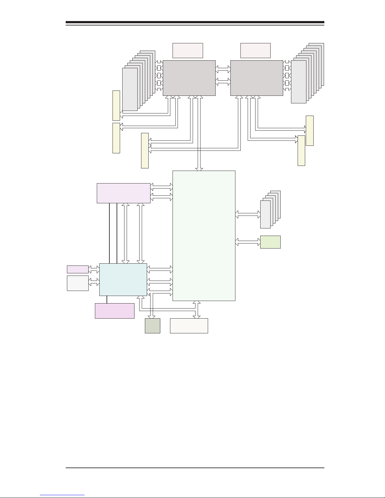
the motherboard. (See Figure 1-1 for a block diagram of the chipset.)
Processors
The motherboard supports single or dual Intel E5-2600 v3 Series processors in
LGA2011 sockets (Socket R3). Refer to the Supermicro web site for a complete
listing of supported processors (www.supermicro.com).
Memory
The motherboard has 16 sockets that can support up to 1 TB of LRDIMM (LoadReduced DIMMs) or 512 GB of RDIMM (Registered DIMMs). Memory type is ECC
DDR4 SRAM, 2133/1866/1600 MHz.
Onboard Serial ATA
The motherboard has six SATA 3.0 connections from Intel PCH (SATA1-6) with two
SATA ports used for SuperDOMs (Device-on-Module) with power supply built in.
RAID 0, 1, 5 and 10 are supported by Intel PCH.
Input/Output Ports
The rear I/O ports include two USB 3.0 ports, a dedicated IPMI LAN port, and two
LAN ports. The 1028GQ-TR model offers two Gigabit LAN ports; the 1028GQ-TRT
model features two 10-Gigabit LAN ports. These are all presented on the chassis
rear by means of the add-on module.
A VGA port is also available on the chassis rear.
Also available on the motherboard are one COM header and a header for two
USB 2.0 ports.
Graphics Controller
The motherboard features an integrated ASpeed AST2400 BMC graphics chip.
Page 11
1-3
Chapter 1: Introduction
Figure 1-1. Intel C612 Chipset:
System Block Diagram
Note: This is a general block diagram. Please see Chapter 5 for details.
#1-4
#1-5
#1-6
#1-7
#1-8
#2-4
#2-5
#2-6
#2-7
#2-8
SPI
RGRMII
Debug Card
PCI-E X1 G2
USB 2.0
#12 USB2.0
#1-4
PCH
C612
6.0 Gb/S
LPC
#1
#0
SATA3
#5
#4
#3
#2
SPI
Temp Sensor
EMC1402-1 *2
at diff SMBUS
TPM HEADER
AST2400
BMC
#5
BMC
Boot Flash
DDR3
SLOT 3
5 PHASE
145W
DDR4
P1
P1
P0
VR12.5
P0
#1-3
#1-2
QPI
9.6G
SLOT 4
PCI-E X16 G3
(LANE REVERSED IN RSC-G-6)
DMI2
PCI-E X16
PCI-E X16 G3
(RSC-GR-6)
2IMD2IMD
CPU2
QPI
9.6G
4GB/s
5 PHASE
145W
VR12.5
PCI-E X16
#3
SLOT 1
PCI-E X16
PCI-E X16
SLOT2
PCI-E X16 G3
(LANE REVERSED IN RSC-G-6)
PCI-E X16 G3
(LANE REVERSED IN RSC-G-6)
#1 #2 #3#2 #1
<=1.758W (average)
2.3W (Peak)
TDP:6.5W (WORKSTATION)
5W (SERVER)
USB & SATA useage different
Idle:0.45W
5V:1.2A
3.3V:0.1A
3.3 STBY:0.2A
1.05 PCH
1.05 ASW
1.5 PCH
PVCCIO 1.0/0.95
3.3STBY:0.5A
VCCP1 12v
VCCP0 12v
AOM-PIO-i2G/i2XT
RMII/NCSI
SLOT 5
PCI-E X8/X8
PCI-E X8 G4 (RSC-GR-A88)
PCI-E X8 G3 (RSC-GR-A88)
Redriver for x8 from CPU1
PCI-E X4 G2
VGA
COM PORT
USB3.0 x2
1333/2133
DDR4
#2-3
#2-2
#2-1
BIOS
USB2.0 x2
USB 2.0
Header
Rear IO
riser card
CPU1
DDR4
DDR4
1333/2133
#1-1
Page 12

1-4
SUPERSERVER 1028GQ-TR(T) User's Manual
1-3 Chassis Features
The 1028GQ-TR(T) is built upon the SC118GQE-R2K03P chassis. The following
are the main features.
System Power
The chassis features a redundant 2 KW power supply consisting of two hot-plug
power modules. They have 80 Plus certication at Platinum Level (94%) high-
efciency. The system will continue to operate if one module fails or is replaced.
Hard Drives
The chassis supports two 2.5" hot-swap hard drives and two internal xed 2.5"
hard drives.
GPU and PCI Expansion Slots
The system offers four PCI-E 3.0 x16 slots that support optional graphics processing
units (GPUs)/Xeon Phi cards, plus two low prole PCI-E 3.0 x8 slots.
The system supports graphics processing units K1/K2/K40M/K80/Xeon Phi.
Front Control Panel
The chassis front control panel provides system monitoring and power control.
Status LEDs indicate system power, HDD activity, network activity, UID, and
overheat and fan failure.
Cooling System
The chassis has nine 4-cm heavy duty, counter-rotating fans, plus an air shroud to
direct air. Fan speed can be controlled by system temperature using IPMI. Each
power supply module also includes a cooling fan.
Page 13

1-5
Chapter 1: Introduction
1-4 Contacting Supermicro
Headquarters
Address: Super Micro Computer, Inc.
980 Rock Ave.
San Jose, CA 95131 U.S.A.
Tel: +1 (408) 503-8000
Fax: +1 (408) 503-8008
Email: marketing@supermicro.com (General Information)
support@supermicro.com (Technical Support)
Web Site: www.supermicro.com
Europe
Address: Super Micro Computer B.V.
Het Sterrenbeeld 28, 5215 ML
's-Hertogenbosch, The Netherlands
Tel: +31 (0) 73-6400390
Fax: +31 (0) 73-6416525
Email: sales@supermicro.nl (General Information)
support@supermicro.nl (Technical Support)
rma@supermicro.nl (Customer Support)
Web Site: www.supermicro.nl
Asia-Pacic
Address: Super Micro Computer, Inc.
3F, No. 150, Jian 1st Rd.
Zhonghe Dist., New Taipei City 235
Taiwan (R.O.C)
Tel: +886-(2) 8226-3990
Fax: +886-(2) 8226-3992
Email: support@supermicro.com.tw
Web Site: www.supermicro.com.tw
Page 14

1-6
SUPERSERVER 1028GQ-TR(T) User's Manual
Notes
Page 15

Chapter 2: Server Installation
2-1
Chapter 2
Server Installation
2-1 Overview
This chapter provides a quick setup checklist to get your system up and running.
This quick setup assumes that your system has come to you with the processors
and memory preinstalled. If your system is not already fully integrated with a
serverboard, processors, system memory etc., please turn to the chapter or section
noted in each step for details on installing specic components.
2-2 Unpacking the System
You should inspect the box the chassis was shipped in and note if it was damaged
in any way. If the chassis itself shows damage, le a damage claim with the carrier
who delivered it.
2-3 Preparing for Setup
Decide on a suitable location for the rack unit that will hold your chassis. It should
be a clean, dust-free area that is well ventilated. Avoid areas where heat, electrical
noise and electromagnetic elds are generated. A nearby grounded power outlet.
is required
The box your chassis was shipped in should include two sets of rail assemblies, two
rail mounting brackets and the mounting screws to mount the system into the rack.
Please read this chapter in its entirety before beginning the installation procedure.
Choosing a Setup Location
• Leave enough clearance in front of the rack to enable you to open the front door
completely (~25 inches) and approximately 30 inches of clearance in the back
of the rack to allow for sufcient airow and ease in servicing.This product is for
installation only in a Restricted Access Location (dedicated equipment rooms,
service closets and the like).
• This product is not suitable for use with visual display work place devices
acccording to §2 of the the German Ordinance for Work with Visual Display Units.
Page 16

2-2
SUPERSERVER 1028GQ-TR(T) User's Manual
2-4 Warnings and Precautions
Rack Precautions
• Ensure that the leveling jacks on the bottom of the rack are fully extended to
the oor with the full weight of the rack resting on them.
• In single rack installation, stabilizers should be attached to the rack. In multiple
rack installations, the racks should be coupled together.
• Always make sure the rack is stable before extending a component from the
rack.
• You should extend only one component at a time - extending two or more
simultaneously may cause the rack to become unstable.
• Rack-mounted equipment should not be used as a shelf or work space.
Server Precautions
• Review the electrical and general safety precautions in Chapter 4.
• Determine the placement of each component in the rack before you install the
rails.
• Install the heaviest server components on the bottom of the rack rst, and then
work up.
• Use a regulating uninterruptible power supply (UPS) to protect the server from
power surges, voltage spikes and to keep your system operating in case of a
power failure.
• Allow the hot plug SATA drives and power supply modules to cool before
touching them.
• Always keep the rack's front door and all panels and components on the servers
closed when not servicing to maintain proper cooling.
Page 17
Chapter 2: Server Installation
2-3
Rack Mounting Considerations
Ambient Operating Temperature
If installed in a closed or multi-unit rack assembly, the ambient operating
temperature of the rack environment may be greater than the ambient temperature
of the room. Therefore, consideration should be given to installing the equipment
in an environment compatible with the manufacturer’s maximum rated ambient
temperature (Tmra).
Reduced Airow
Equipment should be mounted into a rack so that the amount of airow required
for safe operation is not compromised.
Mechanical Loading
Equipment should be mounted into a rack so that a hazardous condition does not
arise due to uneven mechanical loading.
Circuit Overloading
Consideration should be given to the connection of the equipment to the power
supply circuitry and the effect that any possible overloading of circuits might have
on overcurrent protection and power supply wiring. Appropriate consideration of
the equipment nameplate ratings should be used when addressing this concern.
Reliable Ground
A reliable ground must be maintained at all times. To ensure this, the rack
itself should be grounded. Particular attention should be given to power supply
connections other than the direct connections to the branch circuit (i.e. the use of
power strips, etc.).
Warning! To prevent bodily injury when mounting or servicing this unit in a
rack, you must take special precautions to ensure that the system remains
stable. The following guidelines are provided to ensure your safety:
• This unit should be mounted at the bottom of the rack if it is the only unit in
the rack.
• When mounting this unit in a partially lled rack, load the rack from the bottom
to the top with the heaviest component at the bottom of the rack.
• If the rack is provided with stabilizing devices, install the stabilizers before
mounting or servicing the unit in the rack.
• Slide rail mounted equipment is not to be used as a shelf or a work space.
Page 18
2-4
SUPERSERVER 1028GQ-TR(T) User's Manual
2-5 Installing the System into a Rack
There are a variety of rack units on the market, which may require a slightly different
assembly procedure. This rail set ts a rack between 25.6" and 33" deep.
The following is a basic guideline for installing the system into a rack with the rack
mounting hardware provided. You should also refer to the installation instructions
that came with the specic rack you are using.
Identifying the Sections of the Rails
The chassis comes with two sets of rack rails, one set for the right side of the
chassis and one for the left. Each set consists of an inner rail that is pre-attached
to the chassis, and an outer rail that attaches to the rack.
Figure 2-1. Identifying the Sections of the Rack Rails
Front and Rear
Brackets--
attach to the rack
Outer Rails--
slide together
Inner Rails--
pre-installed
Page 19

Chapter 2: Server Installation
2-5
Figure 5-3. Assembling the Outer Rails
Assembling the Outer Rails
Each outer rail comes in two sections that must be assembled before mounting
onto the rack.
Assembling the Outer Rails
1. Identify the left and right outer rails by examining the ends, which bend outward.
Match the left front outer rail with the left rear outer rail and the same for the
right rails.
2. Align the round post in the rear rail (B) with the round hole at the end of the slot
in the front rail (A), and slide the front section into the rear section.
Outer rail assembled
Secure to the
front of the rack
Secure to the
rear of the rack
Slide outer rails
together
Assembling the sections of
the outer rail
1
A
1
B
Round Hole
Bracket with
Square Pegs
Page 20
2-6
SUPERSERVER 1028GQ-TR(T) User's Manual
Figure 2-4. Installing the Outer Rails to the Rack
Installing the Outer Rails onto the Rack
Each end of the assembled outer rail includes a bracket with square pegs to t into
your rack holes. If you have an older rack with round holes, these brackets must be
removed, and you must use screws to secure the rail to the rack.
Outer Rail Installation
1. Align the square pegs on the front end of the rail with the square holes on the
front of the rack (C). Push the rail into the rack until the quick release bracket
snaps into place, securing the rail to the rack. Keep the rail horizontal.
2. Adjust the rail to reach just past the full depth of your rack.
3. Align the square pegs on the rear end of the rail to the holes on the rack (D)
and push the rail into the rack until the quick release bracket snaps into place,
securing the rail to the rack.
Note: The gure above is for illustrative purposes only. Always install servers at
the bottom of the rack rst.
Stability hazard. The rack stabilizing mechanism must be in place, or the
rack must be bolted to the oor before you slide the unit out for servicing.
Failure to stabilize the rack can cause the rack to tip over.
1
C
1
D
Page 21
Chapter 2: Server Installation
2-7
Installing and Removing the Chassis From a Rack
Installing the Chassis into a Rack
1. Align the rear of the chassis rails with the front of the rack rails and then push
evenly on both sides of the chassis. The spring latch engages when the chassis
is part way in. Push the server completely into the rack.
2. (Optional) Insert and tighten the thumbscrews that hold the front of the server
to the rack.
Removing the Chassis From a Rack
1. Press the outer rail latch to release the chassis.
2. Carefully slide the chassis forward, off the outer rails and out of the chassis.
Figure 2-5. Server Installation and Removal
L_max=
840.0(33.0") (OUTER RAIL)
L_max=
840.0(33.0") (OUTER RAIL)
INNER RAIL_BACK
Outer Rail
Latch
Note: The gure above is for illustrative purposes only. Always install servers at
the bottom of the rack rst.
Warning: Do not pick up the server with the front handles. They are designed
to pull the system from a rack only.
Page 22

2-8
SUPERSERVER 1028GQ-TR(T) User's Manual
Notes
Page 23
Chapter 3: System Interface
3-1
Chapter 3
System Interface
3-1 Overview
The server includes a control panel on the front that houses power buttons and
status monitoring lights, status lights on the externally accessible hard drives, and
status lights for the power supply visible from the back of the chassis
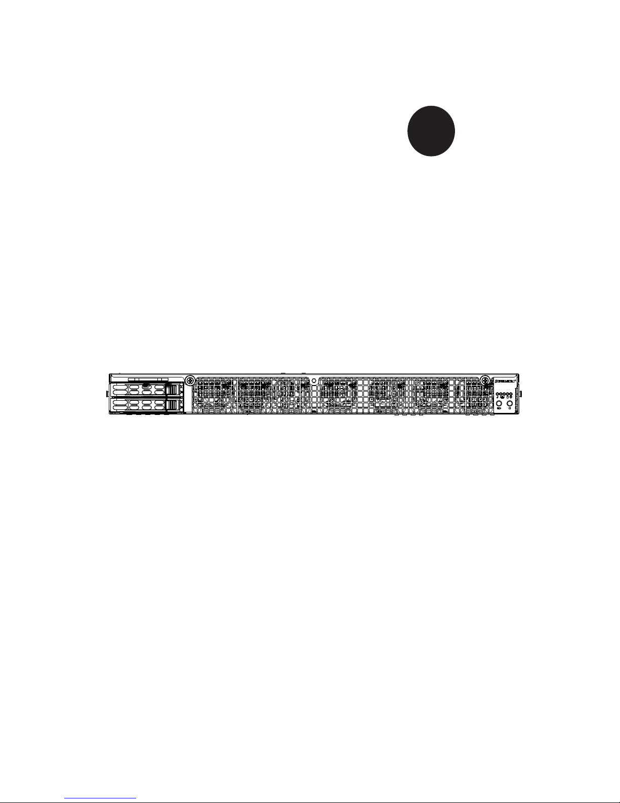
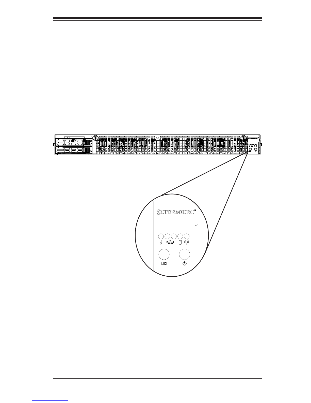
Figure 3-1. Control Panel
Page 24
SuperServer 1028GQ-TR(T) User's Manual
3-2
3-3 Control Panel LEDs
There are ve LEDs that provide status information about the system.
Power
The main power switch is used to apply or remove power from the power supply
to the server system. Turning off system power with this button removes the main
power but keeps standby power supplied to the system. Therefore, you must unplug
system before servicing.
Unit Identication
The uinit identication (UID) button turns on or off the blue light function of the
Information LED and a blue LED on the rear of the chassis. These are used to
locate the server in large racks and server banks.
3-2 Control Panel Buttons
The chassis includes two push-buttons that control power to the system.
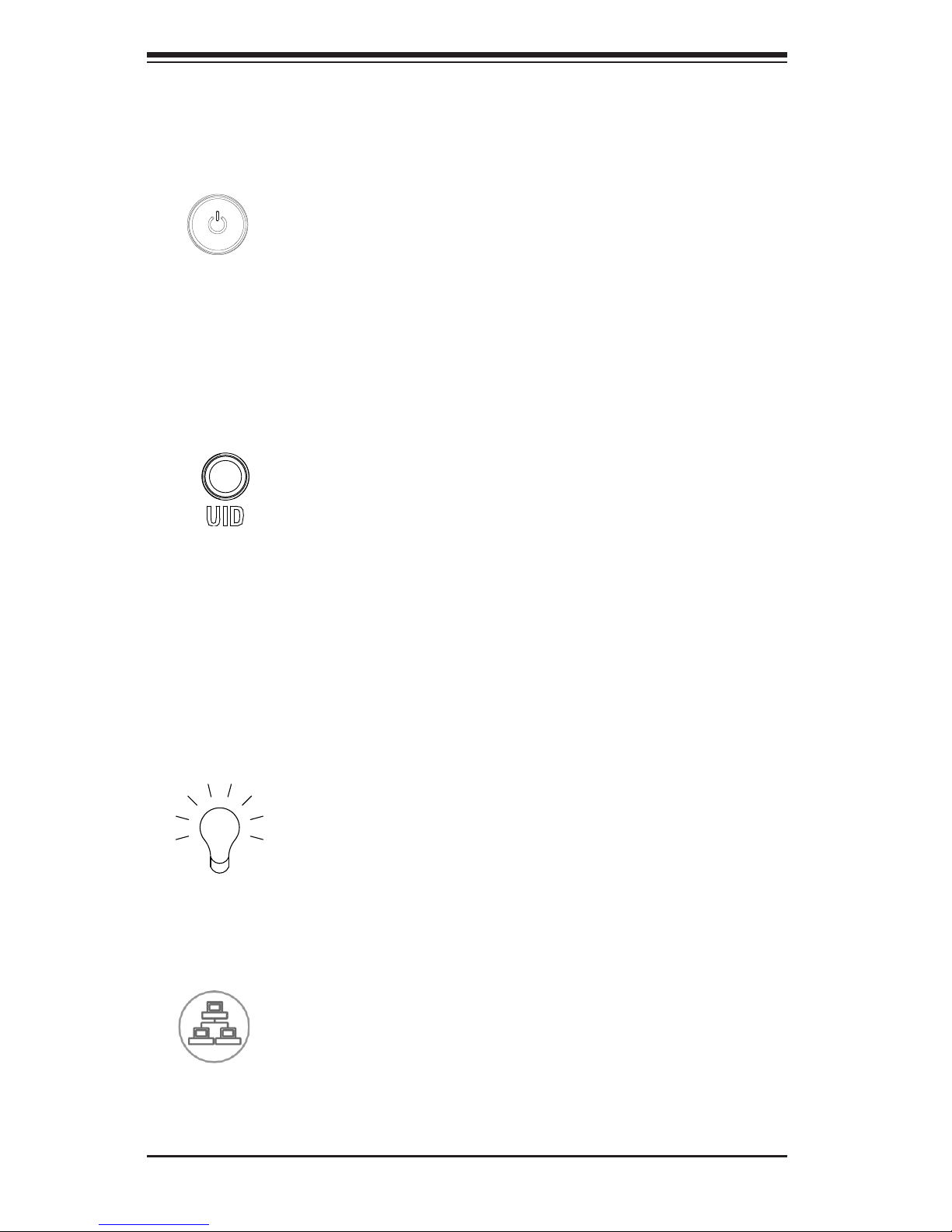
Power
Indicates power is being supplied to the system power supply units. This LED should
normally be illuminated when the system is operating.
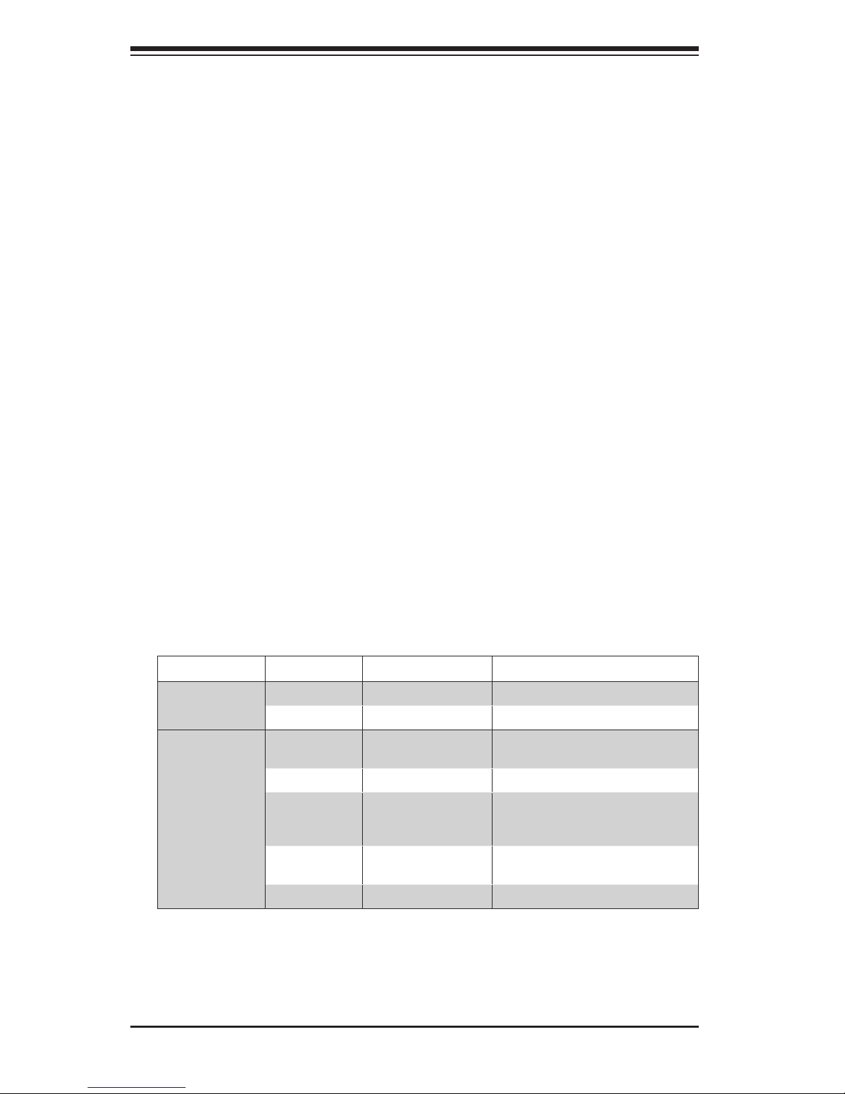
NIC2 and NIC1
Indicates network activity on LAN2 or LAN1 when ashing.
1
2
Page 25
Chapter 3: System Interface
3-3
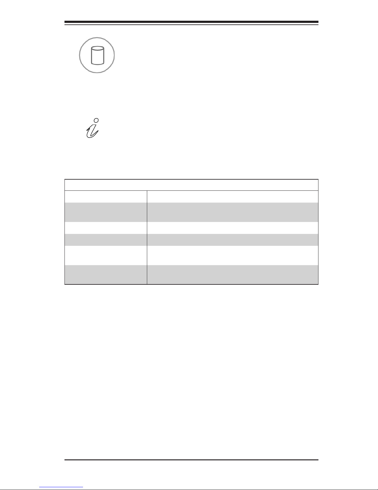
HDD
Indicates activity on the hard drive when ashing.
Information LED
Alerts operator of several states, as noted in the table below.
Information LED
Status Description
Continuously on and red
An overheat condition has occured.
(This may be caused by cable congestion.)
Blinking red (1Hz) Fan failure, check for an inoperative fan.
Blinking red (0.25Hz) Power failure, check for a non-operational power supply.
Solid blue
Local UID has been activated. Use this function to locate
the server in a rack mount environment.
Blinking blue
Remote UID is on. Use this function to identify the
server from a remote location.
Page 26
SuperServer 1028GQ-TR(T) User's Manual
3-4
Overheating
There are several possible responses if the system overheats.
Overheat Temperature Setting
Some backplanes allow the overheat temperature to be set at 45, 50, or 55 by
changing a jumper setting. For more information, consult the backplane user manual
at www.supermicro.com. (Click Support, then the Manuals link.)
Responses
If the server overheats:
1. Use the LEDs to determine the nature of the overheating condition.
2. Conrm that the chassis covers are installed properly.
3. Check the routing of the cables and make sure all fans are present and operating
normally.
4. Verify that the heatsinks are installed properly.
3-4 Drive Carrier LEDs
The chassis includes externally accessible SAS/SATA drives. Each drive carrier
displays two status LEDs on the front of the carrier.
LED Color Blinking Pattern Behavior for Device
Activity LED
Blue Solid On SAS drive installed
Blue Blinking I/O activity
Status LED
Red Solid On Failure of drive with RSTe
support
Red Blinking at 1 Hz Rebuild drive with RSTe support
Red Blinking with two
blinks and one stop
at 1 Hz
Hot spare for drive with RSTe
support
Red On for ve
seconds, then off
Power on for drive with RSTe
support
Red Blinking at 4 Hz Identify drive with RSTe support
Page 27

Chapter 3: System Interface
3-5
3-5 Power Supply LEDs
On the rear of the power supply module, an LED displays the status.
• Solid Green: When illuminated, indicates that the power supply is on.
• Solid Amber: When illuminated, indicates the power supply is plugged in and
turned off, or the system is off but in an abnormal state.
• Blinking Amber: When blinking, this system power supply temperature has
reached 63C. The system will automatically power-down when the power supply
temperature reaches 70C and restart when the power supply temperature goes
below 60C.
Page 28

SuperServer 1028GQ-TR(T) User's Manual
3-6
Notes
Page 29
4-1
Chapter 4: Warning Statements for AC Systems
Chapter 4
Standardized Warning Statements for AC Systems
About Standardized Warning Statements
The following statements are industry standard warnings, provided to warn the user
of situations which have the potential for bodily injury. Should you have questions
or experience difficulty, contact Supermicro's Technical Support department
for assistance. Only certied technicians should attempt to install or congure
components.
Read this chapter in its entirety before installing or conguring components in the
Supermicro chassis. Some warnings may not apply for your system.
These warnings may also be found on our web site at www.supermicro.com/about/
policies/safety_information.cfm.
Warning!
This warning symbol means danger. You are in a situation that could cause bodily
injury. Before you work on any equipment, be aware of the hazards involved with
electrical circuitry and be familiar with standard practices for preventing accidents.
Warning Denition
警告の定義
この警 告 サインは 危 険 を意 味します。
人身事故につながる可能性がありますので、いずれの機器でも動作させる前に、
電気回路に含まれる危険性に注意して、標準的な事故防止策に精通して下さい。
此警告符号代表危险。
您正处于可能受到严重伤害的工作环境中。在您使用设备开始工作之前,必须充分
意识到触电的危险,并熟练掌握防止事故发生的标准工作程序。请根据每项警告结
尾的声明号码找到此设备的安全性警告说明的翻译文本。
此警告符號代表危險。
您正處於可能身體可能會受損傷的工作環境中。在您使用任何設備之前,請注意觸
電的危險,並且要熟悉預防事故發生的標準工作程序。請依照每一注意事項後的號
碼找到相關的翻譯說明內容。
Page 30
4-2
SUPERSERVER 1028GQ-TR(T) User's Manual
Warnung
WICHTIGE SICHERHEITSHINWEISE
Dieses Warnsymbol bedeutet Gefahr. Sie benden sich in einer Situation, die zu
Verletzungen führen kann. Machen Sie sich vor der Arbeit mit Geräten mit den
Gefahren elektrischer Schaltungen und den üblichen Verfahren zur Vorbeugung
vor Unfällen vertraut. Suchen Sie mit der am Ende jeder Warnung angegebenen
Anweisungsnummer nach der jeweiligen Übersetzung in den übersetzten
Sicherheitshinweisen, die zusammen mit diesem Gerät ausgeliefert wurden.
BEWAHREN SIE DIESE HINWEISE GUT AUF.
INSTRUCCIONES IMPORTANTES DE SEGURIDAD
Este símbolo de aviso indica peligro. Existe riesgo para su integridad física. Antes
de manipular cualquier equipo, considere los riesgos de la corriente eléctrica y
familiarícese con los procedimientos estándar de prevención de accidentes. Al
nal de cada advertencia encontrará el número que le ayudará a encontrar el texto
traducido en el apartado de traducciones que acompaña a este dispositivo.
GUARDE ESTAS INSTRUCCIONES.
IMPORTANTES INFORMATIONS DE SÉCURITÉ
Ce symbole d'avertissement indique un danger. Vous vous trouvez dans une
situation pouvant entraîner des blessures ou des dommages corporels. Avant
de travailler sur un équipement, soyez conscient des dangers liés aux circuits
électriques et familiarisez-vous avec les procédures couramment utilisées pour
éviter les accidents. Pour prendre connaissance des traductions des avertissements
gurant dans les consignes de sécurité traduites qui accompagnent cet appareil,
référez-vous au numéro de l'instruction situé à la n de chaque avertissement.
CONSERVEZ CES INFORMATIONS.
Page 31

4-3
Chapter 4: Warning Statements for AC Systems
4-3
안전을 위한 주의사항
경고!
이 경고 기호는 위험이 있음을 알려 줍니다. 작업자의 신체에 부상을 야기 할 수
있는 상태에 있게 됩니다. 모든 장비에 대한 작업을 수행하기 전에 전기회로와
관련된 위험요소들을 확인하시고 사전에 사고를 방지할 수 있도록 표준
작업절차를 준수해 주시기 바랍니다.
해당 번역문을 찾기 위해 각 경고의 마지막 부분에 제공된 경고문 번호를
참조하십시오
BELANGRIJKE VEILIGHEIDSINSTRUCTIES
Dit waarschuwings symbool betekent gevaar. U verkeert in een situatie die
lichamelijk letsel kan veroorzaken. Voordat u aan enige apparatuur gaat werken,
dient u zich bewust te zijn van de bij een elektrische installatie betrokken risico's
en dient u op de hoogte te zijn van de standaard procedures om ongelukken te
voorkomen. Gebruik de nummers aan het eind van elke waarschuwing om deze te
herleiden naar de desbetreffende locatie.
BEWAAR DEZE INSTRUCTIES
Page 32

4-4
SUPERSERVER 1028GQ-TR(T) User's Manual
Installation Instructions
Warning!
Read the installation instructions before connecting the system to the power source.
Warnung
Vor dem Anschließen des Systems an die Stromquelle die Installationsanweisungen
lesen.
¡Advertencia!
Lea las instrucciones de instalación antes de conectar el sistema a la red de
alimentación.
Attention
Avant de brancher le système sur la source d'alimentation, consulter les directives
d'installation.
設置手順書
システムを電源に接続する前に、設置手順書をお読み下さい。
시스템을 전원에 연결하기 전에 설치 안내를 읽어주십시오.
Waarschuwing
Raadpleeg de installatie-instructies voordat u het systeem op de voedingsbron
aansluit.
警告
将此系统连接电源前,请先阅读安装说明。
警告
將系統與電源連接前,請先閱讀安裝說明。
Page 33

4-5
Chapter 4: Warning Statements for AC Systems
Circuit Breaker
Warning!
This product relies on the building's installation for short-circuit (overcurrent)
protection. Ensure that the protective device is rated not greater than: 250 V, 20 A.
サーキット・ブレーカー
この製品は、短絡(過電流)保護装置がある建物での設置を前提としています。
保護装置の定格が250 V、20 Aを超えないことを確認下さい。
Warnung
Dieses Produkt ist darauf angewiesen, dass im Gebäude ein Kurzschlussbzw. Überstromschutz installiert ist. Stellen Sie sicher, dass der Nennwert der
Schutzvorrichtung nicht mehr als: 250 V, 20 A beträgt.
¡Advertencia!
Este equipo utiliza el sistema de protección contra cortocircuitos (o sobrecorrientes)
del edicio. Asegúrese de que el dispositivo de protección no sea superior a: 250
V, 20 A.
Attention
Pour ce qui est de la protection contre les courts-circuits (surtension), ce produit
dépend de l'installation électrique du local. Vériez que le courant nominal du
dispositif de protection n'est pas supérieur à :250 V, 20 A.
警告
此产品的短路(过载电流)保护由建筑物的供电系统提供,确保短路保护设备的额定电
流不大于250V,20A。
警告
此產品的短路(過載電流)保護由建築物的供電系統提供,確保短路保護設備的額定電
流不大於250V,20A。
Page 34

4-6
SUPERSERVER 1028GQ-TR(T) User's Manual
Power Disconnection Warning
電源切断の警告
システムコンポーネントの取り付けまたは取り外しのために、シャーシー内部にアクセス
するには、
システムの電源はすべてのソースから切断され、電源コードは電源モジュールから取り
外す必要があります。
警告
在你打开机箱并安装或移除内部器件前,必须将系统完全断电,并移除电源线。
警告
在您打開機殼安裝或移除內部元件前,必須將系統完全斷電,並移除電源線。
Warnung
Das System muss von allen Quellen der Energie und vom Netzanschlusskabel
getrennt sein, das von den Spg.Versorgungsteilmodulen entfernt wird, bevor es
auf den Chassisinnenraum zurückgreift, um Systemsbestandteile anzubringen oder
zu entfernen.
Warning!
The system must be disconnected from all sources of power and the power cord
removed from the power supply module(s) before accessing the chassis interior to
install or remove system components.
경고!
이 제품은 전원의 단락(과전류)방지에 대해서 전적으로 건물의 관련 설비에
의존합니다. 보호장치의 정격이 반드시 250V(볼트), 20A(암페어)를 초과하지
않도록 해야 합니다.
Waarschuwing
Dit product is afhankelijk van de kortsluitbeveiliging (overspanning) van
uw electrische installatie. Controleer of het beveiligde aparaat niet groter
gedimensioneerd is dan 220V, 20A.
Page 35

4-7
Chapter 4: Warning Statements for AC Systems
¡Advertencia!
El sistema debe ser disconnected de todas las fuentes de energía y del cable
eléctrico quitado de los módulos de fuente de alimentación antes de tener acceso
el interior del chasis para instalar o para quitar componentes de sistema.
Attention
Le système doit être débranché de toutes les sources de puissance ainsi que de
son cordon d'alimentation secteur avant d'accéder à l'intérieur du chassis pour
installer ou enlever des composants de systéme.
경고!
시스템에 부품들을 장착하거나 제거하기 위해서는 섀시 내부에 접근하기 전에
반드시 전원 공급장치로부터 연결되어있는 모든 전원과 전기코드를 분리해주어야
합니다.
Waarschuwing
Voordat u toegang neemt tot het binnenwerk van de behuizing voor het installeren
of verwijderen van systeem onderdelen, dient u alle spanningsbronnen en alle
stroomkabels aangesloten op de voeding(en) van de behuizing te verwijderen
Page 36

4-8
SUPERSERVER 1028GQ-TR(T) User's Manual
Equipment Installation
機器の設置
トレーニングを受け認定された人だけがこの装置の設置、交換、またはサービスを許可
されています。
Warning!
Only trained and qualied personnel should be allowed to install, replace, or service
this equipment.
Warnung
Das Installieren, Ersetzen oder Bedienen dieser Ausrüstung sollte nur geschultem,
qualiziertem Personal gestattet werden.
¡Advertencia!
Solamente el personal calicado debe instalar, reemplazar o utilizar este equipo.
Attention
Il est vivement recommandé de confier l'installation, le remplacement et la
maintenance de ces équipements à des personnels qualiés et expérimentés.
경고!
훈련을 받고 공인된 기술자만이 이 장비의 설치, 교체 또는 서비스를 수행할 수
있습니다.
警告
只有经过培训且具有资格的人员才能进行此设备的安装、更换和维修。
警告
只有經過受訓且具資格人員才可安裝、更換與維修此設備。
Page 37

4-9
Chapter 4: Warning Statements for AC Systems
アクセス制限区域
このユニットは、アクセス制限区域に設置されることを想定しています。
アクセス制限区域は、特別なツール、鍵と錠前、その他のセキュリティの手段を用いての
み出入りが可能です。
Warning!
This unit is intended for installation in restricted access areas. A restricted access
area can be accessed only through the use of a special tool, lock and key, or other
means of security. (This warning does not apply to workstations).
Restricted Area
Waarschuwing
Deze apparatuur mag alleen worden geïnstalleerd, vervangen of hersteld door
geschoold en gekwaliceerd personeel.
Warnung
Diese Einheit ist zur Installation in Bereichen mit beschränktem Zutritt vorgesehen.
Der Zutritt zu derartigen Bereichen ist nur mit einem Spezialwerkzeug, Schloss und
Schlüssel oder einer sonstigen Sicherheitsvorkehrung möglich.
¡Advertencia!
Esta unidad ha sido diseñada para instalación en áreas de acceso restringido.
Sólo puede obtenerse acceso a una de estas áreas mediante la utilización de una
herramienta especial, cerradura con llave u otro medio de seguridad.
Attention
Cet appareil doit être installée dans des zones d'accès réservés. L'accès à une
zone d'accès réservé n'est possible qu'en utilisant un outil spécial, un mécanisme
de verrouillage et une clé, ou tout autre moyen de sécurité.
警告
此部件应安装在限制进出的场所,限制进出的场所指只能通过使用特殊工具、锁和
钥匙或其它安全手段进出的场所。
警告
此裝置僅限安裝於進出管制區域,進出管制區域係指僅能以特殊工具、鎖頭及鑰匙
或其他安全方式才能進入的區域。
Page 38

4-10
SUPERSERVER 1028GQ-TR(T) User's Manual
Battery Handling
Warning!
There is the danger of explosion if the battery is replaced incorrectly. Replace the
battery only with the same or equivalent type recommended by the manufacturer.
Dispose of used batteries according to the manufacturer's instructions
경고!
이 장치는 접근이 제한된 구역에 설치하도록 되어있습니다. 특수도구, 잠금 장치
및 키, 또는 기타 보안 수단을 통해서만 접근 제한 구역에 들어갈 수 있습니다.
Waarschuwing
Dit apparaat is bedoeld voor installatie in gebieden met een beperkte toegang.
Toegang tot dergelijke gebieden kunnen alleen verkregen worden door gebruik te
maken van speciaal gereedschap, slot en sleutel of andere veiligheidsmaatregelen.
電池の取り扱い
電池交換が正しく行われなかった場合、破裂の危険性があります。 交換する電池はメー
カーが推奨する型、または同等のものを使用下さい。 使用済電池は製造元の指示に従
って処分して下さい。
警告
电池更换不当会有爆炸危险。请只使用同类电池或制造商推荐的功能相当的电池更
换原有电池。请按制造商的说明处理废旧电池。
警告
電池更換不當會有爆炸危險。請使用製造商建議之相同或功能相當的電池更換原有
電池。請按照製造商的說明指示處理廢棄舊電池。
Page 39

4-11
Chapter 4: Warning Statements for AC Systems
Warnung
Bei Einsetzen einer falschen Batterie besteht Explosionsgefahr. Ersetzen Sie die
Batterie nur durch den gleichen oder vom Hersteller empfohlenen Batterietyp.
Entsorgen Sie die benutzten Batterien nach den Anweisungen des Herstellers.
Attention
Danger d'explosion si la pile n'est pas remplacée correctement. Ne la remplacer
que par une pile de type semblable ou équivalent, recommandée par le fabricant.
Jeter les piles usagées conformément aux instructions du fabricant.
¡Advertencia!
Existe peligro de explosión si la batería se reemplaza de manera incorrecta.
Reemplazar la batería exclusivamente con el mismo tipo o el equivalente
recomendado por el fabricante. Desechar las baterías gastadas según las
instrucciones del fabricante.
경고!
배터리가 올바르게 교체되지 않으면 폭발의 위험이 있습니다. 기존 배터리와
동일하거나 제조사에서 권장하는 동등한 종류의 배터리로만 교체해야 합니다.
제조사의 안내에 따라 사용된 배터리를 처리하여 주십시오.
Waarschuwing
Er is ontplofngsgevaar indien de batterij verkeerd vervangen wordt. Vervang de
batterij slechts met hetzelfde of een equivalent type die door de fabrikant aanbevolen
wordt. Gebruikte batterijen dienen overeenkomstig fabrieksvoorschriften afgevoerd
te worden.
Page 40

4-12
SUPERSERVER 1028GQ-TR(T) User's Manual
Warnung
Dieses Gerät kann mehr als eine Stromzufuhr haben. Um sicherzustellen, dass
der Einheit kein trom zugeführt wird, müssen alle Verbindungen entfernt werden.
¡Advertencia!
Puede que esta unidad tenga más de una conexión para fuentes de alimentación.
Para cortar por completo el suministro de energía, deben desconectarse todas las
conexiones.
Attention
Cette unité peut avoir plus d'une connexion d'alimentation. Pour supprimer toute
tension et tout courant électrique de l'unité, toutes les connexions d'alimentation
doivent être débranchées.
Redundant Power Supplies (if applicable to your system)
Warning!
This unit might have more than one power supply connection. All connections must
be removed to de-energize the unit.
冗長電源装置
このユニットは複数の電源装置が接続されている場合があります。
ユニットの電源を切るためには、すべての接続を取り外さなければなりません。
警告
此部件连接的电源可能不止一个,必须将所有电源断开才能停止给该部件供电。
警告
此裝置連接的電源可能不只一個,必須切斷所有電源才能停止對該裝置的供電。
Page 41

4-13
Chapter 4: Warning Statements for AC Systems
Backplane Voltage (if applicable to your system)
バックプレーンの電圧
システムの稼働中は危険な電圧または電力が、バックプレーン上にかかっています。
修理する際 には注 意ください。
警告
当系统正在进行时,背板上有很危险的电压或能量,进行维修时务必小心。
警告
當系統正在進行時,背板上有危險的電壓或能量,進行維修時務必小心。
Warnung
Wenn das System in Betrieb ist, treten auf der Rückwandplatine gefährliche
Spannungen oder Energien auf. Vorsicht bei der Wartung.
¡Advertencia!
Cuando el sistema está en funcionamiento, el voltaje del plano trasero es peligroso.
Tenga cuidado cuando lo revise.
Attention
Lorsque le système est en fonctionnement, des tensions électriques circulent sur
le fond de panier. Prendre des précautions lors de la maintenance.
Warning!
Hazardous voltage or energy is present on the backplane when the system is
operating. Use caution when servicing.
경고!
이 장치에는 한 개 이상의 전원 공급 단자가 연결되어 있을 수 있습니다. 이
장치에 전원을 차단하기 위해서는 모든 연결 단자를 제거해야만 합니다.
Waarschuwing
Deze eenheid kan meer dan één stroomtoevoeraansluiting bevatten. Alle
aansluitingen dienen verwijderd te worden om het apparaat stroomloos te maken.
Page 42

4-14
SUPERSERVER 1028GQ-TR(T) User's Manual
Comply with Local and National Electrical Codes
Warning!
Installation of the equipment must comply with local and national electrical codes.
地方および国の電気規格に準拠
機器の取り付けはその地方および国の電気規格に準拠する必要があります。
Warnung
Die Installation der Geräte muss den Sicherheitsstandards entsprechen.
¡Advertencia!
La instalacion del equipo debe cumplir con las normas de electricidad locales y
nacionales.
경고!
시스템이 동작 중일 때 후면판 (Backplane)에는 위험한 전압이나 에너지가 발생
합니다. 서비스 작업 시 주의하십시오.
Waarschuwing
Een gevaarlijke spanning of energie is aanwezig op de backplane wanneer het
systeem in gebruik is. Voorzichtigheid is geboden tijdens het onderhoud.
警告
设备安装必须符合本地与本国电气法规。
警告
設備安裝必須符合本地與本國電氣法規。
Page 43

4-15
Chapter 4: Warning Statements for AC Systems
Product Disposal
Warning!
Ultimate disposal of this product should be handled according to all national laws
and regulations.
Attention
L'équipement doit être installé conformément aux normes électriques nationales
et locales.
경고!
현 지역 및 국가의 전기 규정에 따라 장비를 설치해야 합니다.
Waarschuwing
Bij installatie van de apparatuur moet worden voldaan aan de lokale en nationale
elektriciteitsvoorschriften.
製品の廃棄
この製品を廃棄処分する場合、国の関係する全ての法律・条例に従い処理する必要が
あります。
警告
本产品的废弃处理应根据所有国家的法律和规章进行。
警告
本產品的廢棄處理應根據所有國家的法律和規章進行。
Warnung
Die Entsorgung dieses Produkts sollte gemäß allen Bestimmungen und Gesetzen
des Landes erfolgen.
Page 44

4-16
SUPERSERVER 1028GQ-TR(T) User's Manual
Waarschuwing
De uiteindelijke verwijdering van dit product dient te geschieden in overeenstemming
met alle nationale wetten en reglementen.
¡Advertencia!
Al deshacerse por completo de este producto debe seguir todas las leyes y
reglamentos nacionales.
Attention
La mise au rebut ou le recyclage de ce produit sont généralement soumis à des
lois et/ou directives de respect de l'environnement. Renseignez-vous auprès de
l'organisme compétent.
Warning!
The fans might still be turning when you remove the fan assembly from the chassis.
Keep ngers, screwdrivers, and other objects away from the openings in the fan
assembly's housing.
Hot Swap Fan Warning (if applicable to your system)
ファン・ホ ット ス ワッ プ の 警 告
シャーシから冷却ファン装置を取り外した際、ファンがまだ回転している可能性がありま
す。 ファンの開口部に、指、ドライバー、およびその他のものを近づけないで下さい。
警告
当您从机架移除风扇装置,风扇可能仍在转动。小心不要将手指、螺丝起子和其他
物品太靠近风扇
경고!
이 제품은 해당 국가의 관련 법규 및 규정에 따라 폐기되어야 합니다.
Page 45

4-17
Chapter 4: Warning Statements for AC Systems
Warnung
Die Lüfter drehen sich u. U. noch, wenn die Lüfterbaugruppe aus dem Chassis
genommen wird. Halten Sie Finger, Schraubendreher und andere Gegenstände
von den Öffnungen des Lüftergehäuses entfernt.
¡Advertencia!
Los ventiladores podran dar vuelta cuando usted quite ell montaje del ventilador
del chasis. Mandtenga los dedos, los destornilladores y todos los objetos lejos de
las aberturas del ventilador
Attention
Il est possible que les ventilateurs soient toujours en rotation lorsque vous retirerez
le bloc ventilateur du châssis. Prenez garde à ce que doigts, tournevis et autres
objets soient éloignés du logement du bloc ventilateur.
경고!
섀시로부터 팬 조립품을 제거할 때 팬은 여전히 회전하고 있을 수 있습니다. 팬
조림품 외관의 열려있는 부분들로부터 손가락 및 스크류드라이버, 다른 물체들이
가까이 하지 않도록 배치해 주십시오.
Waarschuwing
Het is mogelijk dat de ventilator nog draait tijdens het verwijderen van het
ventilatorsamenstel uit het chassis. Houd uw vingers, schroevendraaiers
en eventuele andere voorwerpen uit de buurt van de openingen in de
ventilatorbehuizing.
警告
當您從機架移除風扇裝置,風扇可能仍在轉動。小心不要將手指、螺絲起子和其他
物品太靠近風扇。
Page 46

4-18
SUPERSERVER 1028GQ-TR(T) User's Manual
Warning!
When installing the product, use the provided or designated connection cables,
power cables and AC adaptors. Using any other cables and adaptors could cause
a malfunction or a re. Electrical Appliance and Material Safety Law prohibits the
use of UL or CSA -certied cables (that have UL/CSA shown on the code) for any
other electrical devices than products designated by Supermicro only.
Power Cable and AC Adapter
Warnung
Bei der Installation des Produkts, die zur Verfügung gestellten oder benannt
Anschlusskabel, Stromkabel und Netzteile. Verwendung anderer Kabel und Adapter
kann zu einer Fehlfunktion oder ein Brand entstehen. Elektrische Geräte und
Material Safety Law verbietet die Verwendung von UL-oder CSA-zertizierte Kabel,
UL oder CSA auf der Code für alle anderen elektrischen Geräte als Produkte von
Supermicro nur bezeichnet gezeigt haben.
¡Advertencia!
Al instalar el producto, utilice los cables de conexión previstos o designados, los
cables y adaptadores de CA. La utilización de otros cables y adaptadores podría
ocasionar un mal funcionamiento o un incendio. Aparatos Eléctricos y la Ley de
Seguridad del Material prohíbe el uso de UL o CSA cables certicados que tienen
UL o CSA se muestra en el código de otros dispositivos eléctricos que los productos
designados por Supermicro solamente.
電源コードとACアダプター
製品を設置する場合、提供または指定された接続ケーブル、電源コードとACアダプター
を使用下さい。 他のケーブルやアダプタを使用すると故障や火災の原因になることがあ
ります。 電気用品安全法は、ULまたはCSA認定のケーブル(UL/CSEマークがコードに表
記)を Supermicroが指定する製品以外に使用することを禁止しています。
警告
安装此产品时,请使用本身提供的或指定的连接线,电源线和电源适配器.使用其它线
材或适配器可能会引起故障或火灾。除了Supermicro所指定的产品,电气用品和材料
安全法律规定禁止使用未经UL或CSA认证的线材。(线材上会显示UL/CSA符号)。
警告
安裝此產品時,請使用本身提供的或指定的連接線,電源線和電源適配器.使用其它線
材或適配器可能會引起故障或火災。除了Supermicro所指定的產品,電氣用品和材料
安全法律規定禁止使用未經UL或CSA認證的線材。(線材上會顯示UL/CSA符號)。
Page 47

4-19
Chapter 4: Warning Statements for AC Systems
Attention
Lors de l'installation du produit, utilisez les bables de connection fournis ou désigné.
L'utilisation d'autres cables et adaptateurs peut provoquer un dysfonctionnement
ou un incendie. Appareils électroménagers et de loi sur la sécurité Matériel interdit
l'utilisation de UL ou CSA câbles certiés qui ont UL ou CSA indiqué sur le code
pour tous les autres appareils électriques que les produits désignés par Supermicro
seulement.
경고!
제품을 설치할 때에는 제공되거나 지정된 연결케이블과 전원케이블, AC어댑터를
사용해야 합니다. 그 밖의 다른 케이블들이나 어댑터들은 고장 또는 화재의 원인이
될 수 있습니다. 전기용품안전법 (Electrical Appliance and Material Safety
Law)은 슈퍼마이크로에서 지정한 제품들 외에는 그 밖의 다른 전기 장치들을
위한 UL또는 CSA에서 인증한 케이블(전선 위에 UL/CSA가 표시)들의 사용을
금지합니다.
Waarschuwing
Bij het installeren van het product, gebruik de meegeleverde of aangewezen kabels,
stroomkabels en adapters. Het gebruik van andere kabels en adapters kan leiden
tot een storing of een brand. Elektrisch apparaat en veiligheidsinformatiebladen wet
verbiedt het gebruik van UL of CSA gecerticeerde kabels die UL of CSA die op
de code voor andere elektrische apparaten dan de producten die door Supermicro
alleen.
Page 48

4-20
SUPERSERVER 1028GQ-TR(T) User's Manual
Notes
Page 49

Chapter 5: Advanced Serverboard Setup
5-1
Chapter 5
Advanced Motherboard Setup
This chapter covers the steps required to install processors and heatsinks to the
X10DGQ motherboard, connect the data and power cables and install add-on
cards. All motherboard jumpers and connections are described and a layout and
quick reference chart are included in this chapter. Remember to close the chassis
completely when you have nished working on the motherboard to protect and
cool the system sufciently.
5-1 Handling the Motherboard
Static electrical discharge can damage electronic com ponents. To prevent damage
to printed circuit boards, it is important to handle them very carefully (see Chapter
4). Also note that the size and weight of the motherboard can cause it to bend if
handled improperly, which may result in damage. To prevent the motherboard from
bending, keep one hand under the center of the board to support it when handling.
The following measures are generally sufcient to protect your equipment from
static discharge.
Precautions
• Use a grounded wrist strap designed to prevent static discharge.
• Touch a grounded metal object before removing any board from its antistatic
bag.
• Handle a board by its edges only; do not touch its components, peripheral
chips, memory modules or gold contacts.
• When handling chips or modules, avoid touching their pins.
• Put the motherboard, add-on cards and peripherals back into their antistatic
bags when not in use.
Unpacking
The motherboard is shipped in antistatic packaging to avoid static damage. When
unpacking the board, make sure the person handling it is static protected.
Page 50

5-2
SUPERSERVER 1028GQ-TR(T) User's Manual
5-2 Installing the Processor and Heatsink
Notes:
• Always remove the power cord before adding, removing or changing a CPU.
• When receiving a motherboard without a processor pre-installed, make sure
that the plastic CPU socket cap is in place and none of the socket pins are
bent; otherwise, contact your retailer immediately.
• If you buy a CPU separately, use only an Intel-certied, multi-directional
heatsink.
• Avoid placing direct pressure to the top of the processor package.
• Install the processor into the CPU socket before installing the heatsink.
• Refer to the Supermicro web site for updates on CPU support.
Installing an LGA 2011 Processor
Release
the lever labeled "Open 1st"
Installing a CPU
1. There are two levers on the LGA 2011
socket. First press and release the
load lever labeled "Open 1st".
OPEN 1st
OPEN 1st
Release
the lever labeled "Close 1st"
2. Press the second load lever labeled
"Close 1st" to release the load plate
from its locked position.
Page 51

Chapter 5: Advanced Serverboard Setup
5-3
3. With the second lever fully
retracted, gently push down on
the "Open 1st" lever to loosen the
load plate. Lift the load plate with
your ngers to open it completely.
4. Pop the plastic cap marked
"Warning" out of the load plate.
5. Holding the CPU carefully above
the socket, orient the CPU so
that all keys and edges will t the
socket.
OPEN 1st
IMPORTANT!
Caution: You can only install the CPU into the socket in one direction. Make sure
that the CPU is properly inserted into the socket before closing the load plate. If it
does not close properly, do not force it as it may damage your CPU. Instead, open
the load plate again and double-check that the CPU is aligned properly.
Open the load
plate.
6. Carefully lower the CPU straight
down into the socket. Do not
move the CPU horizontally, and
do not rub the pins of the socket.
This may damage the CPU or the
socket.
Page 52

5-4
SUPERSERVER 1028GQ-TR(T) User's Manual
8. Make sure the locking mechanism
on the "Close 1st" lever catches the
lip of the load plate. Close and lock
the "Close 1st" lever.
Push down and lock
the
lever labeled "Open 1st"
OPEN 1st
OPEN 1st
Push down and lock the
lever labeled "Close 1st".
9. Close and lock the "Open 1st" lever.
Engage the lip of
the load plate and
locking portion of
the lever."
7. With the "Close 1st" lever fully
retracted, gently close the load
plate.
Gently close
the load plate.
Page 53

Chapter 5: Advanced Serverboard Setup
5-5
Figure 5-1. Heatsinks
Figure 5-2. Heatsink Screw Order
Installing a Heatsink
1. Place the heatsink on top of the CPU so that the four mounting holes are aligned
with those on the retention mechanism.
2. Screw in two diagonal screws (#1 and #2) until just snug—do not over-tighten
and damage the CPU. Screw in the remaining screws.
3. Finish the installation by fully tightening all four screws.
Screw #1
Screw #2
Screw #3
Screw #4
Installing a CPU Heatsink
Page 54

5-6
SUPERSERVER 1028GQ-TR(T) User's Manual
Removing the Heatsink
Caution: We do not recommend removing the CPU or the heatsink. If you do need
to remove the heatsink, please follow the instructions below to prevent damage to
the CPU or the CPU socket.
1. Unplug the power cord from the power supply.
2. Unscrew and remove the heatsink screws in the opposite sequence shown in
the picture above.
3. Hold the heatsink and gently wriggle it to loosen it from the CPU. (Do not use
excessive force!)
4. Once the heatsink is loosened, remove it from the CPU.
5. Clean the surface of the CPU and the heatsink to get rid of the old thermal
grease. Reapply the proper amount of thermal grease before re-installing the
heatsink.
Page 55

Chapter 5: Advanced Serverboard Setup
5-7
5-3 Connecting Cables
Now that the processors are installed, the next step is to connect the cables to the
motherboard. These include the data (ribbon) cables for the peripherals and control
panel and the power cables.
Connecting Data Cables
The cables used to transfer data from the peripheral devices have been carefully
routed in precongured systems to prevent them from blocking the ow of cooling
air that moves through the system from front to back. If you need to disconnect any
of these cables, you should take care to reroute them as they were originally after
reconnecting them and be aware of the pin 1 locations. If you are conguring the
system, keep the airow in mind when routing the cables.
Connecting Power Cables
The motherboard has two 50-pin primary power supply connectors designated
JPW1 and JPW2. Connect the appropriate cable connectors from the power supply
to JPW1 and JPW2 to provide power to the motherboard.
Connecting the Control Panel
JF1 contains header pins for the front control panel connectors. All JF1 wires have
been bundled into single keyed ribbon cable to simplify their connection. The red
wire in the ribbon cable plugs into pin 1 of JF1. Connect the other end of the cable
to the Control Panel printed circuit board, located just behind the system status
LEDs in the chassis.
See the Connector Denitions section in this chapter for details and pin descriptions
of JF1.
Page 56

5-8
SUPERSERVER 1028GQ-TR(T) User's Manual
5-4 Input/Output Ports
The rear panel I/O ports are connected to the motherboard by means of the addon module.
Figure 5-2. Rear Panel I/O Ports
1 6
5
4
3
2
1. USB 3.0 Port
2. USB 3.0 Port
3. LAN 1
4. LAN 2
5. IPMI dedicated LAN
6. VGA (blue)
LAN Ports
The 1028GQ-TR model offers two Gigabit LAN ports; the 1028GQ-TRT model
features two 10-Gigabit LAN ports.
Page 57

Chapter 5: Advanced Serverboard Setup
5-9
5-5 Installing Memory
For best performance, install memory modules of the same type and
same speed in the slots as indicated in the tables on the following page.
Note: Check the Supermicro web site for recommended memory modules.
CAUTION
Exercise extreme care when installing or removing DIMM modules
to prevent any possible damage.
Installing DIMMs
1. Insert the desired number of DIMMs into the memory slots, starting with slot
P1-DIMMA1.
2. Push the release tabs outwards on both ends of the DIMM slot to unlock it.
3. Insert each DIMM vertically into its slot. Pay attention to the notch along the
bottom of the module to prevent inserting the DIMM module incorrectly..
4. Use two thumbs together to press on both ends of the module straight down
into the slot until the module snaps into place.
Figure 5-3. Installing DIMM into Slot
Socket Key
Release Tab
Release Tab
Releasing Memory Modules
Press the release tabs on both ends of the memory module to unlock it. Once it is
loosened, remove the DIMM module from the memory slot.
Page 58

5-10
SUPERSERVER 1028GQ-TR(T) User's Manual
Memory Support
The server features 16 DIMM slots that can support up to 1 TB of Load Reduction
(LRDIMM) or up to 512 GB of Registered (RDIMM)/Non-volatile (NV-DIMM) ECC
DDR4-2133/1866/1600 MHz memory. Memory speed support depends on the
processors installed in the system. For the latest memory updates, refer to the
Supermicro website at www.supermicro.com/products/motherboard.
Processor and Memory Module Population Conguration
For memory to work properly, follow the tables below for memory installation.
Processors and their Corresponding Memory Modules
CPU# Corresponding DIMM Modules
CPU 1 P1-
DIMMA1
P1DIMMB1
P1DIMMC1
P1DIMMD1
P1DIMMA2
P1DIMMB2
P1DIMMC2
P1DIMMD2
CPU2 P2-
DIMME1
P2DIMMF1
P2DIMMG1
P2DIMMH1
P2DIMME2
P2DIMMF2
P2DIMMG2
P2DIMMH2
Processor and Memory Module Population for Optimal Performance
Number of
CPUs+DIMMs
CPU and Memory Population Conguration Table
(For memory to work properly, please follow the instructions below.)
1 CPU &
2 DIMMs
CPU1
P1-DIMMA1/P1-DIMMB1
1 CPU &
4 DIMMs
CPU1
P1-DIMMA1/P1-DIMMB1, P1-DIMMC1/P1-DIMMD1
1 CPU &
5~8 DIMMs
CPU1
P1-DIMMA1/P1-DIMMB1, P1-DIMMC1/P1-DIMMD1 + Any memory pairs in P1DIMMA2/P1-DIMMB2/P1-DIMMC2/P1-DIMMD2 slots
2 CPUs &
4 DIMMs
CPU1 + CPU2
P1-DIMMA1/P1-DIMMB1, P2-DIMME1/P2-DIMMF1
2 CPUs &
6 DIMMs
CPU1 + CPU2
P1-DIMMA1/P1-DIMMB1/P1-DIMMC1/P1-DIMMD1, P2-DIMME1/P2-DIMMF1
2 CPUs &
8 DIMMs
CPU1 + CPU2
P1-DIMMA1/P1-DIMMB1/P1-DIMMC1/P1-DIMMD1, P2-DIMME1/P2-DIMMF1/P2DIMMG1/P2-DIMMH1
2 CPUs &
8~16 DIMMs
CPU1/CPU2
P1-DIMMA1/P1-DIMMB1/P1-DIMMC1/P1-DIMMD1, P2-DIMME1/P2-DIMMF1/P2DIMMG1/P2-DIMMH1 + Any memory pairs in P1, P2 DIMM slots
2 CPUs &
16 DIMMs
CPU1/CPU2
P1-DIMMA1/P1-DIMMB1/P1-DIMMC1/P1-DIMMD1, P2-DIMME1/P2-DIMMF1/P2-DIMMG1/P2-DIMMH1,P1-DIMMA2/P1-DIMMB2/P1-DIMMC2/P1-DIMMD2, P2-DIMME2/
P2-DIMMF2/P2-DIMMG2/P2-DIMMH2
Caution: For the memory to work properly, install DIMMs of the same type and
speed.
Page 59

Chapter 5: Advanced Serverboard Setup
5-11
Populating RDIM/LRDIMM DDR4 ECC Memory Modules
Speed (MT/s), Slot per Channel
(SPC) & DIMM per Channel (DPC)
Page 60

5-12
SUPERSERVER 1028GQ-TR(T) User's Manual
Figure 5-4. X10DGQ Layout
5-6 Motherboard Details
Notes
• " " indicates the location of "Pin 1".
• Jumpers/LEDs not indicated are for testing purposes only. Also, components
that are not documented in this manual are reserved for internal use only.
IPMI CODE
JPCIE2
JSLOT6
JPCIE3
LEDM1
LE2
JTPM1
JPW6
JPW5
JPW4
JPW3
JPW2
JPW1
JL1
JITP1
JWD1
JVRM2
JVRM1
JPME2
JPG1
JPB1
J23
FAN9
FAN8
FAN11
FAN10
BT1
JBT1
FAN_PWR1
HDD_PWR2
HDD_PWR1
LE6
SP1
T-SGPIO1
SATA4
SATA3
SATA2
SATA1
SATA6
SATA5
JSD2
JF1
FAN5
JSTBY1
BAR CODE
BIOS
LICENSE
SIO
CPU0/CPU1 SLOT5 PCIE 3.0 X8/X8
CPU1 SLOT4 PCIE 3.0 X16
CPU1 SLOT3 PCIE 3.0 X16
CPU2 SLOT2 PCIE 3.0 X16
CPU2 SLOT1 PCIE 3.0 X16
5V
12V
12V
5V
P1-DIMMC1
P1-DIMMC2
P1-DIMMD1
P1-DIMMD2
CPU1
P1-DIMMB2
P1-DIMMB1
P1-DIMMA2
P1-DIMMA1
P2-DIMME2
P2-DIMMF1
P2-DIMMF2
P2-DIMMH2
P2-DIMMH1
P2-DIMMG2
P2-DIMMG1
USB2/3
CPU2
JSD1
BIOS
P2-DIMME1
X10DGQ
Rev. 1.00
PCH
BMC
1
1
1
1
BATTERY
Indicators
LED Description (State) Status
LE2 System Power LED On: System power on
LE6 Power Health LED Green: System power on
LEDM1 BMC Heartbeat LED Green (blinking): BMC normal
Page 61

Chapter 5: Advanced Serverboard Setup
5-13
Motherboard Quick Reference
Jumpers
Jumper Description Default Setting
JBT1 Clear CMOS/Reset BIOS
Conguration
See Chapter 2
JPB1 BMC Enable Pins 1-2 (Enabled)
JPG1 VGA Enable Pins 1-2 (Enabled)
JPME2 Manufacture Mode (ME)
Select
Pins 1-2 (Normal)
JWD1 Watch Dog Pins 1-2 (Reset)
Connectors
Connectors Description
FAN5 9-pin fan header
FAN8-FAN11 CPU/system 4-pin cooling fan headers 8-11
HDD_PWR 1/2 HDD power headers 1/2
FAN_PWR1 Fan power connector
JF1 Front control panel header
JL1 Chassis intrusion header
JSD1/2 SATA DOM (Device-On-Module) power connectors 1/2
JPTM1 TPM (Trusted Platform Module)/Port 80
JPW3/4/5/6 8-pin power connectors 3-6
JPW1/JPW2 Proprietary 50-pin power connectors 1/2
JSTBY1 Standby power header
SATA1-6 SATA connectors 1-6 supported by Intel PCH (SATA5/6: support
Supermicro SuperDOM with power pins built-in)
(CPU1) Slot3/4 PCI-E 3.0 x16 slots 3/4
(CPU2) Slot1/2 PCI-E 3.0 x16 slots 1/2
(CPU0/1) Slot5 PCI-E 3.0 x8/x8 slot 5
SIO Slot Riser card for rear I/O support
SP1 Internal speaker/buzzer
T-SGPIO1 Serial_link General Purpose I/O header 1 (for SATA1-2)
USB2/3 USB 2.0 header w/support of two connections USB 2/3
Page 62

5-14
SUPERSERVER 1028GQ-TR(T) User's Manual
5-7 Connector Denitions
Power Connectors
Two 50-pin proprietary power connectors (JPW1/JPW2) are used to provide main
power to your system. Four 8-pin power connectors, located at JPW3/JPW4/JPW5/
JPW6, provide power to PCI-E expansion cards. In addition, two 4-pin power connectors (HDD_PWR1/HDD_PWR2) are used for onboard HDDs, while another 4-pin
power connector (FAN_PWR1) powers the fan board AOM-QG-FAN.
Caution: To provide adequate power to your system and to avoid damaging
the power supply or the motherboard, be sure to connect all power connectors
mentioned above to the power supply when using the devices mentioned. Failure
in doing so may void the manufacturer warranty on your power supply and
motherboard..
NMI
x (key)
3.3V
UID Switch/Vcc
NIC1 Active LED
NIC2 Active LED
Red: (Blue LED Cathode)
3.3V
Reset Button
Power Button
Ground
x (key)
Power LED
HDD LED
NIC1 Link LED
NIC2 Link LED
Blue: OH/Fan Fail/Power Fail/UID LED
Power Fail LED
Ground
Ground
2 1
20 19
Control Panel Connector
The connector for the control panel on the front of the chassis is JF1.
Figure 5-5. Front Control Panel Header Pins (JF1)
HDD_PWR1/HDD_
PWR2
Pin Denitions
Pins Denition
1-2 Ground
3 +5V
4 +12V
(Required)
12V 8-pin Power
Connector Pin
Denitions
Pins Denition
1 through 3 +12V
4 through 8 Ground
(Required)
(Required)
FAN_PWR1
Pin Denitions
Pins Denition
1-2 Ground
3-4 +12V
Page 63

Chapter 5: Advanced Serverboard Setup
5-15
NMI Button
The non-maskable interrupt button
header is located on pins 19 and 20
of JF1. Refer to the table on the right
for pin denitions.
Power LED
The Power LED connection is located
on pins 15 and 16 of JF1. Refer to the
table on the right for pin denitions.
NMI Button
Pin Denitions (JF1)
Pin# Denition
19 Control
20 Ground
Power LED
Pin Denitions (JF1)
Pin# Denition
15 3.3V
16 PWR LED
NIC1/NIC2 LED
The NIC (Network Interface Controller)
LED connections for GLAN port 1 are
located on pins 11 and 12 of JF1, and
the LED connection for GLAN Port 2
are on pins 9 and 10. Attach the NIC
LED cables here to display network
activity. Refer to the table on the right
for pin denitions.
Note: The NIC LED connections for
10G_LAN Ports 3/4 is located on
LED1.
GLAN 1/2 LED
Pin Denitions (JF1)
Pin# Denition
9 NIC 2 Activity LED
10 NIC 2 Link LED
11 NIC 1 Activity LED
12 NIC 1 Link LED
HDD LED/UID Switch
The HDD LED/UID switch connections
are located on pins 13/14 of JF1.
Attach an LED cable to display HDD
activity. Attach a cable to pin 13 to use
UID button. See the table on the right
for pin denitions.
HDD/UID Switch
Pin Denitions (JF1)
Pin# Denition
13 UID Switch
14 HDD Active
Page 64

5-16
SUPERSERVER 1028GQ-TR(T) User's Manual
Overheat (OH)/Fan Fail/PWR Fail/
UID LED
Connect an LED cable to pins 7 and
8 of Front Control Panel to use the
Overheat/Fan Fail/Power Fail and
UID LED connections. The Red
LED on pin 8 provides warnings of
overheat, fan failure or power failure.
The Blue LED on pin 7 works as
the front panel UID LED indicator.
Refer to the table on the right for pin
denitions.
OH/Fan Fail/ PWR Fail/Blue_
UID LED Pin Denitions (JF1)
Pin# Denition
7 Blue_UID LED
8 OH/Fan Fail/Power Fail
OH/Fan Fail/PWR Fail
LED Status (Red LED)
State Denition
Off Normal
On Overheat
Flashing Fan Fail
Power Fail LED
The Power Fail LED connection
is located on pins 5 and 6 of JF1.
Refer to the table on the right for pin
denitions.
PWR Fail LED
Pin Denitions (JF1)
Pin# Denition
5 3.3V
6 PWR Supply Fail
Reset Button
The Reset Button connection is
located on pins 3 and 4 of JF1. Attach
it to the hardware reset switch on the
computer case. Refer to the table on
the right for pin denitions.
Power Button
The Power Button connection is
located on pins 1 and 2 of JF1.
Momentarily contacting both pins will
power on/off the system. This button
can also be congured to function
as a suspend button (see the Power
Button Mode setting in BIOS). To turn
off the power when set to suspend
mode, depress the button for at least
4 seconds. Refer to the table on the
right for pin denitions.
Reset Button
Pin Denitions (JF1)
Pin# Denition
3 Reset
4 Ground
Power Button
Pin Denitions (JF1)
Pin# Denition
1 Signal
2 Ground
Page 65

Chapter 5: Advanced Serverboard Setup
5-17
4-Pin Fan Header
Pin Denitions
Pin# Denition
1 Ground
2 +12V
3 Tachometer
4 Pulse Width Modulation
(PWM)
Fan Headers
The 4-pin fan headers are backward
compatible with traditional 3-pin fans,
however fan speed control is available
for 4-pin fans only. The fan speeds are
controlled by IPMI.
Headers FAN5 (9-pin) and FAN_
PWR1 (4-pin) connect to the fan
board in the front of the chassis (Fans
1-7). Four-pin headers FAN8-FAN11
connect to the rear GPU fans, and
the PCI and I/O add-on module fans,
if present.
Other Connectors
DOM Power Connectors
Two power connectors for SATA
DOM (Disk On Module) devices are
located at JSD1 and JSD2. These
connectors are used with Supermciro
SuperDOMs to provide backwardcompatible power support to nonSupermicro SATADOMs that require
external power supply.
DOM PWR
Pin Denitions
Pin# Denition
1 +5V
2 Ground
3 Ground
TPM Header/Port 80
A Trusted Platform Module/Port 80
header is located at JTPM1 to provide
TPM support and Port 80 connection.
Use this header to enhance system
performance and data security. See
the table on the right for pin denitions.
TPM/Port 80 Header
Pin Denitions
Pin # Denition Pin # Denition
1 LCLK 2 GND
3 LFRAME# 4 <(KEY)>
5 LRESET# 6 +5V (X)
7 LAD 3 8 LAD 2
9 +3.3V 10 LAD1
11 LAD0 12 GND
13 SMB_CLK4 14 SMB_DAT4
15 +3V_DUAL 16 SERIRQ
17 GND 18 CLKRUN# (X)
19 LPCPD# 20 LDRQ# (X)
Page 66

5-18
SUPERSERVER 1028GQ-TR(T) User's Manual
Chassis Intrusion
A Chassis Intrusion header is located
at JL1. Attach an appropriate cable
from the chassis to alert an intrusion
when the chassis is opened.
Chassis Intrusion
Pin Denitions
Pin# Denition
1 Intrusion Input
2 Ground
Internal Speaker
Pin Denition
Pin# Denitions
Pin 1 Pos. (+) Beep In
Pin 2 Neg. (-) Alarm
Speaker
I-SGPIO2 Header
A Serial-Link General Purpose Input/
Output header (I-SGPIO2) supports a
serial-link interface for onboard SATA
connections.
I-SGPIO
Pin Denitions
Pin# Denition Pin Denition
1 NC 2 NC
3 Ground 4 Data
5 Load 6 Ground
7 Clock 8 N
NC = No Connection
Internal Speaker
The internal speaker (SP1) provides
audible indications for beep codes.
Universal Serial Bus (USB)
Two USB 3.0 ports (USB 0/1) are located on the rear I/O panel. In addition, a
header located next to the PCH chip provides two USB 2.0 connections (USB 2/3).
Cables are not included.
Standby Power Header
The onboard standby power header
is located at JSTBY1 on the motherboard. See the table on the right for
pin denitions. (You must also have a
card with the standby power connector and a cable to use this feature.)
Standby PWR
Pin Denitions
Pin# Denition
1 +5V Standby
2 Ground
3 No Connection
Page 67

Chapter 5: Advanced Serverboard Setup
5-19
SIO Slot
JSLOT6 is the slot for the rear I/O add-on module.
PCI Slot
CPU0/CPU1 SLOT5 PCIE 3.0 x8/x8 is the slot for the riser card (RSC-GR-A88)
that enables two low-prole PCIe expansion cards.
GPU Slots
The slots for the GPU riser cards are:
• CPU2 SLOT1 PCIE 3.0 x16
• CPU2 SLOT2 PCIE 3.0 x16
• CPU1 SLOT3 PCIE 3.0 x16
• CPU1 SLOT4 PCIE 3.0 x16
Page 68

5-20
SUPERSERVER 1028GQ-TR(T) User's Manual
5-8 Jumper Settings
Explanation of Jumpers
To modify the operation of the
motherboard, jumpers can be used
to choose between optional settings.
Jumpers create shorts between two
pins to change the function of the
connector. Pin 1 is identified with
a square solder pad on the printed
circuit board. See the diagram at right
for an example of jumping pins 1 and
2. Refer to the motherboard layout
page for jumper locations.
Note: On two-pin jumpers, "Closed"
means the jumper is on and "Open"
means the jumper is off the pins.
CMOS Clear
JBT1 is used to clear CMOS and will also clear any passwords. Instead of pins,
this jumper consists of contact pads to prevent accidentally clearing the contents
of CMOS.
To clear CMOS
1. First power down the system and unplug the power cord(s).
2. With the power disconnected, short the CMOS pads with a metal object such
as a small screwdriver.
3. Remove the screwdriver (or shorting device).
4. Reconnect the power cord(s) and power on the system.
Note: Do not use the PW_ON connector to clear CMOS.
Connector
Pins
Jumper
Setting
3 2 1
3 2 1
Page 69

Chapter 5: Advanced Serverboard Setup
5-21
VGA Enable/Disable
JPG1 allows you to enable or disable
the onboard VGA port. The default
position is on pins 1 and 2 to enable
VGA.
VGA Enable/Disable
Jumper Settings
Jumper Setting Denition
Pins 1-2 Enabled
Pins 2-3 Disabled
ME Manufacturing Mode Select
Close pin 2 and pin 3 of jumper
JPME2 to bypass SPI ash security
and force the system to operate in
the Manufacturer (ME) mode, allowing
the user to ash the system rmware
from a host server for system setting
modications.
ME Mode Select
Jumper Settings
Jumper Setting Denition
Pins 1-2 Normal (Default)
Pins 2-3 Manufacture Mode
Watch Dog Enable/Disable
Watch Dog (JWD1) is a system monitor that can reboot the system when
a software application hangs. Close
pins 1-2 to reset the system if an application hangs. Close pins 2-3 to
generate non-maskable interrupt signals for the application that hangs.
See the table on the right for jumper
settings. Watch Dog must also be enabled in the BIOS
Watch Dog
Jumper Settings
Jumper Setting Denition
Pins 1-2 Reset
Pins 2-3 NMI
Open Disabled
BMC Enable
Jumper JPB1 allows you to enable
the embedded onboard (Baseboard
Management controller (BMC) to
provide IPMI 2.0 support on the
motherboard.
BMC Enable
Jumper Settings
Jumper Setting Denition
Pins 1-2 BMC Enable
Pins 2-3 Normal
Page 70

5-22
SUPERSERVER 1028GQ-TR(T) User's Manual
IPMI Dedicated LAN LEDs
A dedicated IPMI LAN port is located
on the rear I/O panel. The LED on
the right indicates activity by blinking
amber. The Link LED on the left
indicates the speed of the connection.
It may be green, amber, or off. See the
table on the right..
BMC Heartbeat LED
A BMC Heartbeat LED is located at
LEDM1. When this LED is blinking,
BMC is functioning normally.
IPMI LAN Speed LED
Color Denition
Off 10 Mbps, or No Connection
Green 100 Mbps
Amber 1 Gbps
System PWR
LED Status
State Description
On Power
Normal
System_Power Good LED
The System_Power Good LED is
located at LE2. When it is on, system
power is normal.
Power Health LED
Status
State Description
Green System power on
Amber Standby power
only
Red System power
failure
Power Health LED
An onboard Power Health LED is
located at LE6. See the table at right
for indications.
BMC Heartbeat
LED Status
Color/State Denition
Green:
Blinking
BMC:
Normal
5-9 Onboard Indicators
LAN1/2 Port LEDs
The Ethernet ports on the rear I/O
panel have two indicators. On each
port, the LED on the right indicates
activity by blinking amber. The Link
LED on the left indicates the speed
of the connection. It may be green,
amber, or off. See the table on the
right.
LAN Link Indicator
LED Settings
Color Denition
Off No Connection, 10 or 100
Mbps
Green 10 Gbps (1028GQ-TRT only)
Amber 1 Gbps
Activity LED
Link LED
LAN 1/2
Activity LED
Link LED
IPMI LAN
Page 71

Chapter 5: Advanced Serverboard Setup
5-23
5-10 SATA Ports
Six Serial ATA ports (SATA1-SATA6), supported by the Intel PCH, are located
on the motherboard. SATA5/6, colored in yellow, are used with Supermicro
SuperDOM (Disk-on-Module) connectors with power pins built in. Supermicro
SuperDOM connectors are backward-compatible with regular SATA HDDs and
SATA DOMs that require power cables.
Note: Refer to the Intel SATA HostRAID User's Guide posted on our website at,
http://www.supermicro.com for more information.
Page 72

5-24
SUPERSERVER 1028GQ-TR(T) User's Manual
5-11 Installing Software
The Supermicro ftp site contains drivers and utilities for your system at ftp://ftp.
supermicro.com. Some of these must be installed, such as the chipset driver.
After accessing the ftp site, go into the CDR_Images directory and locate the ISO
le for your motherboard. Download this le to create a CD/DVD of the drivers and
utilities it contains. (You may also use a utility to extract the ISO le if preferred.)
Another option is to go to the Supermicro Website at http://www.supermicro.com/
products/. Find the product page for your motherboard here, where you may
download individual drivers and utilities.
After creating a CD/DVD with the ISO les, insert the disk into the CD/DVD drive
on your system and the display shown in Figure 5-6 should appear.
Figure 5-6. Driver Installation Display Screen
Note: Click the icons showing a hand writing on paper to view the readme les
for each item. Click the computer icons to the right of these items to install each
item (from top to the bottom) one at a time. After installing each item, you must
re-boot the system before moving on to the next item on the list. The bottom
icon with a CD on it allows you to view the entire contents.
Page 73

Chapter 5: Advanced Serverboard Setup
5-25
SuperDoctor® 5
The Supermicro SuperDoctor 5 is a hardware and operating system services monitoring program that functions in a command-line or web-based interface in Windows
and Linux operating systems. The program monitors system health information such
as CPU temperature, system voltages, system power consumption, fan speed, and
provides alerts via email or Simple Network Management Protocol (SNMP).
SuperDoctor 5 comes in local and remote management versions and can be used
with Nagios to maximize your system monitoring needs. With SuperDoctor 5 Management Server (SSM Server), you can remotely control power on/off and reset
chassis intrusion for multiple systems with SuperDoctor 5 or IPMI. SD5 Manage-
ment Server monitors HTTP, FTP, and SMTP services to optimize the efciency of
your operation.
Note: The default User Name and Password for SuperDoctor 5 is ADMIN/ADMIN.
Figure 5-7. SuperDoctor 5 Interface Display Screen (Health Information)
Page 74

5-26
SUPERSERVER 1028GQ-TR(T) User's Manual
5-12 Onboard Battery
Please handle used batteries carefully. Do not damage the battery in any way; a
damaged battery may release hazardous materials into the environment. Do not
discard a used battery in the garbage or a public landll. Please comply with the
regulations set up by your local hazardous waste management agency to dispose
of your used battery properly.
Figure 5-9. Installing the Onboard Battery
OR
Note: The SuperDoctor 5 program and User’s Manual can be downloaded from the
Supermicro web site at http://www.supermicro.com/products/nfo/sms_sd5.cfm. For
Linux, we recommend that you use the SuperDoctor II application instead.
Figure 5-8. SuperDoctor 5 Interface Display Screen (Remote Control)
Page 75

Chapter 6: Advanced Chassis Setup
6-1
Chapter 6
Advanced Chassis Setup
This chapter covers the steps required to install components and perform
maintenance on the SC118GQE-RK03 chassis. The only tool required is a Phillips
screwdriver.
Review the warnings and precautions before setting up or servicing components.
These include information in Chapter 4: Warning Statements for AC Systems.
Figure 6-2. Chassis Rear View
Control Panel
Hard Drive Bays (2)
Expansion Slots
Power Supplies
I/O Ports
LAN Ports
Figure 6-1. Chassis Front View
Page 76

6-2
SUPERSERVER 1028GQ-TR(T) User's Manual
6-1 Static-Sensitive Devices
Electrostatic Discharge (ESD) can damage electronic com ponents. To prevent
damage to any printed circuit boards (PCBs), it is important to handle them very
carefully. The following measures are generally sufcient to protect your equipment
from ESD damage.
Precautions
• Use a grounded wrist strap designed to prevent static discharge.
• Touch a grounded metal object before removing any board from its antistatic bag.
• Handle a board by its edges only; do not touch its components, peripheral chips,
memory modules or gold contacts.
• When handling chips or modules, avoid touching their pins.
• Put the serverboard, add-on cards and peripherals back into their antistatic
bags when not in use.
• For grounding purposes, make sure your computer chassis provides excellent
conductivity between the power supply, the case, the mounting fasteners and
the serverboard.
6-2 Removing Power
Before performing most setup or maintenance tasks, ensure that power has been
removed from the system.
1. If the system is operating, use the operating system to power down, following
the on-screen prompts.
2. After the system has completely shut-down, carefully grasp the head of the
power cord and gently pull it out of the back of the power supply. If your system
has dual power supplies, remove the cords from both power supplies.
3. Disconnect the cord from the power strip or wall outlet.
Page 77

Chapter 6: Advanced Chassis Setup
6-3
Figure 6-2. Accessing the Inside of the System
6-3 Removing the Chassis Cover
The SC118GQE has a two piece cover. For either the front cover or the rear cover:
1. Unscrew the two thumb screws on the end of the chassis.
2. Remove the screw securing the cover to each side of the chassis.
3. Pull the cover towards the end of the chassis and off.
Caution: Do not operate the server without the cover in place for long periods
of time. The chassis cover helps to allow proper airow and prevent overheating
Screw
2
Screw
2
1
1
1
1
Page 78

6-4
SUPERSERVER 1028GQ-TR(T) User's Manual
6-5 Hard Drive Installation
The SC118GQE chassis has two externally accessable hot-swap 2.5" drive bays
and space for two internall xed 2.5" drives.
Figure 6-3. Drive Bays
Note: Enterprise level hard disk drives are recommended for use in Supermicro
chassis and servers. For information on recommended HDDs, visit the Supermicro
Web site at http://www.supermicro.com/products/nfo/les/storage/SAS-CompList.
pdf.
Internal HDDs
External HDDs
6-4 Control Panel
The control panel, located on the front of the chassis, must be connected to the JF1
connector on the serverboard to provide you with system status indicators. These
wires have been bundled together as a ribbon cable to simplify the connection.
Connect the cable from JF1 on the serverboard to the appropriate header on the
Control Panel printed circuit board. Make sure the red wire plugs into pin 1 on both
connectors. Pull all excess cabling out of the airow path.
The control panel LEDs inform you of system status. See "Chapter 3: System
Interface" for details. Details on the JF1 header can be found in "Chapter 5:
Advanced Serverboard Setup."
Page 79

Chapter 6: Advanced Chassis Setup
6-5
Figure 6-4. Removing a Drive from the Server
Release Button
Removing Hard Drive Carrier from the Chassis
1. Press the release button on the drive carrier. This extends the drive carrier
handle.
2. Use the handle to pull the drive out of the chassis.
3. Remove the dummy drive from the carrier (Figure 6-5).
Externally Accessable Drives
The two hot-swap drives are mounted in drive carriers to simplify their installation
and removal from the chassis. System power may remain on when removing carriers
with drives installed. These carriers also help promote proper airow for the drive
bays. For this reason, even carriers without drives must remain in the chassis.
Page 80

6-6
SUPERSERVER 1028GQ-TR(T) User's Manual
Drive Carrier
Dummy Drive
Figure 6-5. Removing a Dummy Drive from Carrier
Figure 6-6. Installing a Drive into the Carrier
Installing a Drive into the Carrier
1. Remove the dummy drive from the carrier by removing four screws.
2. Install a new drive into the carrier with the printed circuit board side facing down
so that the mounting holes in the drive align with those in the carrier.
Page 81

Chapter 6: Advanced Chassis Setup
6-7
3. Secure the hard drive into the carrier with the screws.
4. Open the drive carrier handle and use it push the carrier assembly into the
chassis.
5. Gently close the drive carrier handle to secure the drive and carrier into the
chassis drive bay.
Caution: Except for short periods of time while swapping hard drives, do not operate
the server without the carriers in the drive bays.
Page 82

6-8
SUPERSERVER 1028GQ-TR(T) User's Manual
Internal Drives
The system supports one or two 2.5" xed hard disk drives, using the included
mounting bracket.
Installing Internal Drives
1. Mount the drives in the bracket, securing them with screws.
2. Secure the bracket onto the chassis oor.
3. Attach cables from the drives to the motherboard.
Internal HDDs
Figure 6-7. Internal HDD Position
Page 83

Chapter 6: Advanced Chassis Setup
6-9
6-6 Adding Expansion Cards
The system supports up to four graphic processor units (GPUs) and two low-prole
PCIe expansion cards.
Graphic Processor Units
Figure 6-8. Front GPUs
Installing the Front GPUs
Installing the front GPUs requires riser cards, RSC-G-6.
1. Remove the riser card bracket.
2. Attach the riser card to the bracket.
3. Insert the GPU into the riser card slot.
4. Cable up.
Page 84

6-10
SUPERSERVER 1028GQ-TR(T) User's Manual
Figure 6-9. Rear GPU
Installing the rear GPU uses the riser card, RSC-GR-6.
Installing the Rear GPU
1. Remove the chassis bracket.
2. Attach the riser card to the bracket.
3. Insert the GPU into the riser card slot.
4. Cable up. See the next page for routing and cable reference.
5. Insert the riser card into motherboard slot and secure the bracket to chassis rear.
Page 85

Chapter 6: Advanced Chassis Setup
6-11
Cable Reference
Cable Set Part Number Description
(GPU, connector type, length)
Quantity/
Server
K80/M60 CBL-PWEX-0782 GPU1 8pin 55cm 1
CBL-PWEX-0783 GPU2+3 8pin 39cm 2
CBL-PWEX-0814 GPU4 8pin 11cm 1
K40 CBL-PWEX-0784 GPU1 6+2pin 55cm 1
CBL-PWEX-0785 GPU2+3 6+2pin 39cm 2
CBL-PWEX-0786 GPU4 6+2pin 11cm 1
GTX Titan X/
GTX 980TI
CBL-PWEX-0790 GPU1 8pin, 6pin 57cm 1
CBL-PWEX-0791 GPU2+3 8pin, 6pin 36cm 2
CBL-PWEX-0792 GPU4 8pin, 6pin 30cm 1
GTX 980 CBL-PWEX-0815 GPU1 6pin, 6pin 57cm 1
CBL-PWEX-0816 GPU2+3 6pin, 6pin 36cm 2
CBL-PWEX-0817 GPU4 6pin, 6pin 30cm 1
Xeon Phi CBL-PWEX-0787 GPU1 6+2pin, 6pin 57cm 1
CBL-PWEX-0788 GPU2+3 6+2pin, 6pin 38cm 2
CBL-PWEX-0789 GPU4 6+2pin, 6pin 12cm 1
Note: This GPU numbering does not reect GPU detection in IPMI/OS.
Figure 6-10. GPU Cable Routing
Page 86

6-12
SUPERSERVER 1028GQ-TR(T) User's Manual
PCI
A riser card on chassis bracket allows you to add one or two low-prole PCI
expansion cards. All expansion cards are PCI-Express 3.0. Installation requires
the riser card RSC-GR-6.
Installing the Rear PCI Expansion Cards
1. Remove the chassis bracket.
2. Attach the riser card to the bracket.
3. Insert the PCI expansion card into the riser card slot.
4. Cable up.
5. Insert the riser card into motherboard slot and secure the bracket to chassis rear.
Figure 6-10. PCI Expansion Cards
Page 87

Chapter 6: Advanced Chassis Setup
6-13
6-7 Cooling
System Fans
The standard chassis contains nine 4-cm counter-rotating, high-performance fans.
Two more expansion card fans are available.
Fan speed is controlled by system temperature via IPMI. If a fan fails, the remaining
fan will ramp up to full speed and the overheat/fan fail LED on the control panel will
turn on. Replace any failed fan at your earliest convenience with the same type and
model (the system can continue to run with a failed fan).
Remove the top chassis cover while the system is still running to determine which
of the fans has failed. Then power down the system before replacing a fan. .
Replacing System Fans
1. After determining which fan has failed, turn off the system power.
2. Unplug the fan wiring from the serverboard and remove the failed fan.
3. Press the fan release tab to lift the failed fan from the chassis and pull it
completely from the chassis.
Figure 6-11. System Fans
Standard Fans
Optional Fans
Page 88

6-14
SUPERSERVER 1028GQ-TR(T) User's Manual
4. Place the new fan into the vacant space in the housing while making sure the
arrows on the top of the fan (indicating air direction) point in the same direction
as the arrows on the other fans.
5. Power up the system and check that the fan is working properly before replacing
the chassis cover.
Air Shroud and Block
Cooling is also improved by means of an air block and an air shroud to channel the
air ow. The mylar shroud covers the CPUs and memory.
Air Block
Page 89

Chapter 6: Advanced Chassis Setup
6-15
6-8 Power Supply
The 1028GQ-TR(T) has a 2000 watt redundant hot-plug power supply consisting of
two power modules. Each power supply module has an auto-switching capability,
which enables it to automatically sense and operate at a 100V - 240V input voltage.
Replacing a Power Supply Module
If either of the two power supply modules fail, the other module will take the full load
and allow the system to continue operation without interruption. The Power Fail LED
will illuminate and remain on until the failed unit has been replaced. Replacement
units can be ordered directly from Supermicro. Replace the failed hot-swap unit
with another identical power supply unit. The power supply modules can replaced
without powering down the system.
Replacing the Power Supply
1. Unplug the AC power cord from the failed power supply module.
2. Depress the release button on the power supply module.
3. Use the handle to pull the module straight out of the chassis.
4. Push the new power supply unit into the power bay until it clicks.
5. Plug the AC power cord back into the unit and power up the server.
Figure 6-11. Removing/Replacing the Power Supply
Page 90

6-16
SUPERSERVER 1028GQ-TR(T) User's Manual
Notes
Page 91

Chapter 7: AMI BIOS
7-1
Chapter 7
BIOS
7-1 Introduction
This chapter describes the AMI BIOS setup utility for the X10DGQ. It also provides
the instructions on how to navigate the AMI BIOS setup utility screens. The AMI
ROM BIOS is stored in a Flash EEPROM and can be easily updated.
Starting BIOS Setup Utility
To enter the AMI BIOS setup utility screens, press the <Del> key while the system
is booting up.
Note: In most cases, the <Del> key is used to invoke the AMI BIOS setup screen.
There are a few cases when other keys are used, such as <F3>, <F4>, etc.
Each main BIOS menu option is described in this manual. The Main BIOS setup
menu screen has two main frames. The left frame displays all the options that can
be congured. Grayed-out options cannot be congured. Options in blue can be
congured by the user. The right frame displays the key legend. Above the key
legend is an area reserved for informational text. When an option is selected in
the left frame, it is highlighted in white. Often informational text will accompany it.
Note: The AMI BIOS has default informational messages built in. The manufacturer
retains the option to include, omit, or change any of these informational messages.
The AMI BIOS setup utility uses a key-based navigation system called "hot keys."
Most of the AMI BIOS setup utility "hot keys" can be used at any time during setup
navigation. These keys include <F3>, <F4>, <Enter>, <ESC>, arrow keys, etc.
Note 1: Options printed in Bold are default settings.
Note 2: <F3> is used to load optimal default settings. <F4> is used to save the
settings and exit the setup utility.
How To Change the Conguration Data
The conguration data that determines the system parameters may be changed by
entering the AMI BIOS setup utility. This setup utility can be accessed by pressing
<Delete> at the appropriate time during system boot.
Note: For AMI UEFI BIOS Recovery, please refer to the UEFI BIOS Recovery User
Guide posted @ http://www.supermicro.com/support/manuals/.
Page 92

7-2
SuperServer 1028GQ-TR(T) User’s Manual
Starting the Setup Utility
Normally, the only visible Power-On Self-Test (POST) routine is the memory test.
As the memory is being tested, press the <Delete> key to enter the main menu of
the AMI BIOS setup utility. From the main menu, you can access the other setup
screens. An AMI BIOS identication string is displayed at the left bottom corner of
the screen below the copyright message.
Caution: Do not upgrade the BIOS unless your system has a BIOS-related issue.
Flashing the wrong BIOS can cause irreparable damage to the system. In no event
shall the manufacturer be liable for direct, indirect, special, incidental, or consequential
damage arising from a BIOS update. If you have to update the BIOS, do not shut down
or reset the system while the BIOS is being updated to avoid possible boot failure.
7-2 Main Setup
When you rst enter the AMI BIOS setup utility, you will enter the Main setup screen.
You can always return to the Main setup screen by selecting the Main tab on the
top of the screen. The Main BIOS Setup screen is shown below.
Page 93

Chapter 7: AMI BIOS
7-3
The AMI BIOS Main menu displays the following information:
System Date/System Time
Use this item to change the system date and time using the arrow keys. Enter new
values through the keyboard and press <Enter>. Press the <Tab> key to move
between elds. The date must be entered in Day MM/DD/YYYY format. The time is
entered in HH:MM:SS format. (Note: The time is in the 24-hour format. For example,
5:30 P.M. appears as 17:30:00.).
Supermicro X10DGQ
BIOS Version
This item displays the SMC version of the BIOS ROM used in this system.
Build Date
This item displays the date that the BIOS setup utility was built.
CPLD Version
This item displays the version of 'Complex Programmable Logic Device' (CPLD)
used in this system.
Memory Information
Total Memory
This item displays the amount of memory that is available in the system.
Memory Speed
This item displays the speed of memory modules installed in the system.
Page 94

7-4
SuperServer 1028GQ-TR(T) User’s Manual
7-3 Advanced Setup Congurations
Select the Advanced tab to access the following submenu items.
Boot Features
Boot Conguration
Quiet Boot
Use this item to select bootup screen display between POST messages and the
OEM logo. Select Disabled to display the POST messages. Select Enabled to
display the OEM logo instead of the normal POST messages. The options are
Enabled and Disabled.
CSM (Compatibility Support Module) Support
Select Enabled to enable CSM booting support which will allow a UEFI-compatible
device to boot from a system that uses a legacy BIOS ROM. The options are
Enabled and Disabled.
AddOn ROM Display Mode
Use this item to set the display mode for the Option ROM. Select Keep Current to
use the current AddOn ROM Display setting. Select Force BIOS to use the Option
Page 95

Chapter 7: AMI BIOS
7-5
ROM display set by the system BIOS. The options are Force BIOS and Keep
Current.
Bootup Num-Lock
Use this item to set the power-on state for the Numlock key. The options are Off
and On.
Wait For 'F1' If Error
Select Enabled to force the system to wait until the 'F1' key is pressed when an
error occurs. The options are Disabled and Enabled.
Interrupt 19 Capture
Interrupt 19 is the software interrupt that handles the boot disk function. When
this item is set to Immediate, the BIOS ROM of the host adaptors will immediately
capture Interrupt 19 at bootup and allow the drives that are attached to these host
adaptors to function as bootable disks. If this item is set to Postponed, the BIOS
ROM of the host adaptors will only capture Interrupt 19 during bootup from a legacy
device. The options are Immediate and Postponed.
Re-try Boot
If this item is set to Enabled, the system BIOS will continuously try to boot from
the selected boot drive. The options are Disabled, Legacy Boot, and EFI Boot.
Power Conguration
Watch Dog Function
If enabled, the Watch Dog timer will allow the system to automatically reboot when
a non-recoverable error that lasts for more than ve minutes occurs. The options
are Enabled and Disabled.
Power Button Function
If this item is set to Instant Off, the system will power off immediately as soon as
the user presses the power button. If this item is set to 4 Seconds Override, the
system will power off when the user presses the power button for 4 seconds or
longer. The options are Instant Off and 4 Seconds Override.
Restore on AC Power Loss
Use this item to set the power state after a power outage. Select Stay Off for the
system power to remain off after a power outage. Select Power On to turn on the
system power after a power outage. Select Last State to allow the system to resume
its last power state before a power outage. The options are Power On, Stay Off,
and Last State.
Page 96

7-6
SuperServer 1028GQ-TR(T) User’s Manual
CPU Conguration
This submenu displays the following CPU information as detected by the BIOS. It
also allows the user to congure CPU settings.
Processor 0/Processor 1
This submenu displays the following information of the CPU installed in Socket 0,
and Socket 1.
• Processor Socket
• Processor ID
• Processor Frequency
• Processor Max Ratio
• Processor Min Ratio
• Microcode Revision
• L1 Cache RAM
• L2 Cache RAM
• L3 Cache RAM
• Processor 0 Version
• Processor 1 Version
Clock Spread Spectrum
Select Enable to allow the BIOS to attempt to reduce the level of Electromagnetic
Interference caused by the components whenever needed. The options are Disable
and Enable.
Hyper-Threading (All)
Select Enable to support Intel's Hyper-threading Technology to enhance CPU
performance. The options are Enable and Disable.
Cores Enabled
Use this item to set the number of CPU cores to be enabled in your system. Enter
"0" to enable all cores. The default setting is 0.
Execute-Disable Bit (Available if supported by the OS & the CPU)
Select Enable for Execute Disable Bit Technology support, which will allow the
processor to designate areas in the system memory where an application code
can execute and where it cannot, thus preventing a worm or a virus from ooding
illegal codes to overwhelm the processor or damage the system during an attack.
Page 97

Chapter 7: AMI BIOS
7-7
The options are Enable and Disable. (Refer to Intel and Microsoft websites for
more information.)
PPIN Control
Select Unlock/Enable to use the Protected-Processor Inventory Number (PPIN) in
the system. The options are Unlock/Enable and Unlock/Disable.
Hardware Prefetcher (Available when supported by the CPU)
If set to Enable, the hardware prefetcher will prefetch streams of data and
instructions from the main memory to the L2 cache to improve CPU performance.
The options are Disable and Enable.
Adjacent Cache Line Prefetch (Available when supported by the CPU)
Select Enable for the CPU to prefetch both cache lines for 128 bytes as comprised.
Select Disable for the CPU to prefetch both cache lines for 64 bytes. The options
are Disable and Enable.
Note: Please reboot the system for changes on this setting to take effect. Please
refer to Intel’s web site for detailed information.
DCU (Data Cache Unit) Streamer Prefetcher (Available when supported by
the CPU)
If set to Enable, the DCU Streamer Prefetcher will prefetch data streams from the
cache memory to the DCU to speed up data accessing and processing to enhance
CPU performance. The options are Disable and Enable.
DCU IP Prefetcher
If set to Enable, the IP prefetcher in the DCU (Data Cache Unit) will prefetch IP
addresses to improve network connectivity and system performance. The options
are Enable and Disable.
Direct Cache Access (DCA)
Select Enable to use Intel DCA (Direct Cache Access) Technology to improve the
efciency of data transferring and accessing. The options are Enable and Disable.
X2 APIC (Advanced Programmable Interrupt Controller)
Based on Intel's Hyper-Threading architecture, each logical processor (thread)
is assigned 256 APIC IDs (APIDs) in 8-bit bandwidth. When this feature is set to
Enable, the APIC ID will expand from 8 bits (X2) to 16 bits to provide 512 APIDs
to each thread for CPU performance enhancement. The options are Disable and
Enable.
Page 98

7-8
SuperServer 1028GQ-TR(T) User’s Manual
AES-NI
Select Enable to use the Intel Advanced Encryption Standard (AES) New Instructions
(NI) to ensure data security. The options are Enable and Disable.
Intel Virtualization Technology (Available when supported by the CPU)
Select Enable to support Intel Virtualization Technology, which will allow one
platform to run multiple operating systems and applications in independent
partitions, creating multiple "virtual" systems in one physical computer. The options
are Enable and Disable.
Note: If there is a change to this setting, you will need to power off and restart the
system for the change to take effect. Please refer to Intel’s website for detailed
information.)
Advanced Power Management Conguration
Advanced Power Management Conguration
Power Technology
Select Energy Efcient to support power-saving mode. Select Custom to
customize system power settings. Select Disable to disable power-saving
settings. The options are Disable, Energy Efcient, and Custom.
*If the option is set to Custom or Energy Efcient, the following items will display:
Energy Performance Tuning (Available when Power Technology is set to
Custom or Energy Efcient)
Select Enable for energy-performance tuning support to enhance energy
efciency, which might compromise system performance. The options are
Enable and Disable.
Energy Efciency Turbo (Available when Power Technology is set to
Custom or Energy Efcient)
Select Enable for the system to operate at turbo mode with reduced power
consumption so that your machine can achieve maximum system performance
with the maximum power efciency possible. The options are Enable and
Disable.
*If the option is set to Custom, the following items will display:
Page 99

Chapter 7: AMI BIOS
7-9
CPU P State Control (Available when Power
Technology is set to Custom)
EIST (P-states)
EIST (Enhanced Intel SpeedStep Technology) allows the system to automatically
adjust processor voltage and core frequency to reduce power consumption and
heat dissipation. The options are Disable and Enable.
Turbo Mode
Select Enable to use the Turbo Mode to boost system performance. The options
are Disable and Enable.
P-state Coordination
This item is used to change the P-state (Power-Performance State) coordination
type. P-state is also known as "SpeedStep" for Intel processors. Select HW_ALL
to change the P-state coordination type for hardware components only. Select
SW_ALL to change the P-state coordination type for all software installed in the
system. Select SW_ANY to change the P-state coordination type for a software
program in the system. The options are HW_ALL, SW_ALL, and SW_ANY.
CPU C State Control (Available when Power
Technology is set to Custom)
Package C State limit
Use this item to set the limit on the C-State package register. The options are C0/
C1 state, C2 state, C6(non Retention) state, C6 (Retention) state, and No Limit.
CPU C3 Report
Select Enable to allow the BIOS to report the CPU C3 state (ACPI C2) to the
operating system. During the CPU C3 state, the CPU clock generator is turned
off. The options are Disable and Enable.
CPU C6 Report (Available when Power Technology is set to Custom)
Select Enable to allow the BIOS to report the CPU C6 state (ACPI C3) to the
operating system. During the CPU C6 state, power to all cache is turned off.
The options are Disable and Enable.
Enhanced Halt State (C1E)
Select Enable to use the "Enhanced Halt State" feature, which will signicantly
reduce the CPU's power consumption by reducing the CPU's clock cycle and
voltage during a "Halt State." The options are Disable and Enable.
Page 100

7-10
SuperServer 1028GQ-TR(T) User’s Manual
CPU T State Control (Available when Power Technology
is set to Custom)
ACPI (Advanced Conguration Power Interface) T-States
If this item is set to Enable, CPU throttling will be supported by the operating
system to reduce power consumption. The options are Disable and Enable.
Chipset Conguration
North Bridge
This feature is used to congure Intel North Bridge settings.
IIO (Integrated IO) Conguration
EV DFX (Device Function On-Hide) Features
When this item is set to Enable, the EV_DFX Lock Bits that are located on a
processor will always remain clear during electric tuning. The options are Disable
and Enable.
IIO0 Conguration
IOU2 (IIO PCIe Port 1)
This feature allows the user to set the bus speed between the IOU2 and the
PCI-Exp port specied above. The options are x4x4, x8, and Auto.
IOU0 (IIO PCIE Port 2)
This feature allows the user to set the bus speed between the IOU0 and the
PCI-Exp port specied above. The options are x4x4x4x4, x4x4x8, x8x4x4, x8x8,
x16, and Auto.
IOU1 (IIO PCIE Port 3)
This feature allows the user to set the bus speed between the IOU1 and the
PCI-Exp port specied above. The options are x4x4x4x4, x4x4x8, x8x4x4, x8x8,
x16, and Auto.
 Loading...