

Page 1

ANLEITUNG | MANUAL
V 06.17
DE | EN
Page 2
HERZLICHEN GLÜCKWUNSCH | CONGRATULATIONS
Mit diesem Supernova Produkt haben Sie einen treuen
Begleiter erworben. Wir wünschen viel Freude daran!
With this Supernova product you have acquired
a loyal companion. We hope you enjoy it!
Marcus Wallmeyer, CEO & Chief Designer
INHALT | INDEX
WICHTIG | IMPORTANT 4
KONTAKT | CONTACT 4
LIEFERUMFANG | PRODUCT CONTENT 5
BEDIENUNG & FUNKTIONSWEISE | GENERAL USE & FEATURES 6 – 9
MONTAGE | INSTALLATION 11 – 15
2 | 3
Page 3
WICHTIG | IMPORTANT
Lass en Sie die Monta ge von
The Plug s tets von eine m
Fachhändler durchführen.
The Plug e ignet sich nur für
die Mont age in Gabeln mi t
1 1/8“ Gabelschäften mit
Ahead Klemmung.
Always have a qualified
bicycle technician install
The Plug o n your bicycle.
The Plug i s designed to
be mounted in 1 1/8“ fo rk
stems with Aheadset stems.
KONTAKT | CONTACT
Bei Fragen und technischen Problemen
können Sie sich gerne an Supernova direkt
wenden.
You are welcome to contact us directly
regarding all technical questions or in case
of any problems.
SUPERNOVA DESIGN GmbH & Co. KG
Industriestraße 26
79194 Gundelfingen Freiburg
GERMANY
Tel. +49 (0) 761 600 629-0
www.supernova-lights.com
[email protected]
(deutschsprachige Anfragen)
[email protected]
(international questions)
LIEFERUMFANG | PRODUCT CONENT
Art . No. KP653
The Plug
PAT- Kab el
Schraube
Gummiabdeckung
Anleitung
Sticker
Achtung! D er Supernova Th e Plug Expander
ist nicht im Liefer umfang enthalten .
Achtung! D er Supernova Th e Plug Expander
ist nicht im Liefer umfang enthalten .
4 | 5
Page 4

BEDIENUNG & FUNKTIONSWEISE
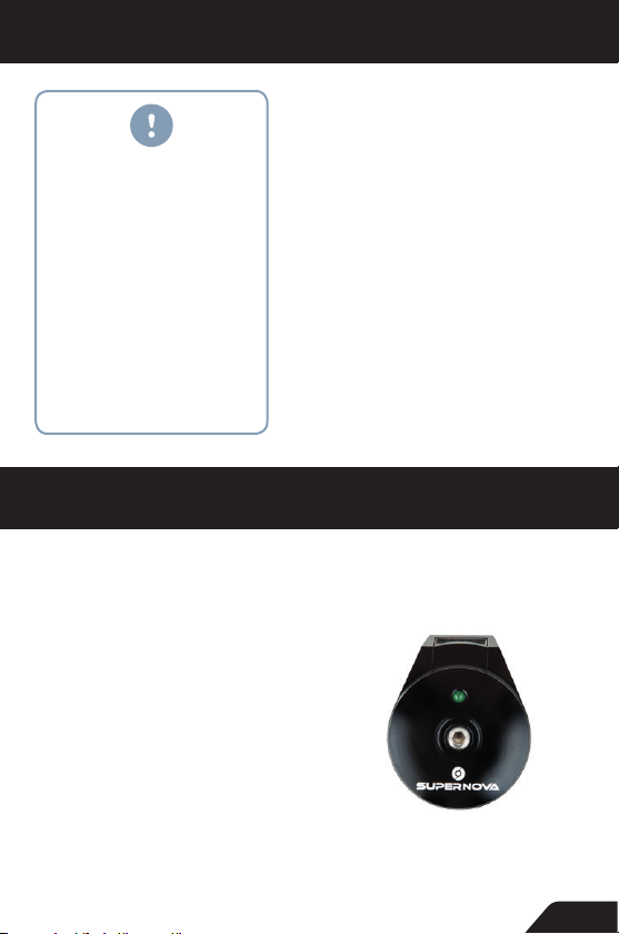
The Plug hat im Leerlauf (ohne Verbraucher) eine zu vernachlässigende Leistun gsaufnahme. S obald die USB-Spannung von 5V (+/ca. 0.2V) zur Ver fügung steh t, leuchtet die grüne LED. Unabhängig
davon ob S trom zum Verbraucher fließt oder nich t. Wird die Spannung ohne eingesteckten Verbraucher zu hoch, schaltet sich the
Plug automatisch ab.
The Plug i st für die Benut zung mit USB betr iebenen Endgeräten
konzipi ert. Die gen aue Funktion alität häng t von Ihrem Endg erät und
dessen Lade- bzw. Betriebseigenschaften über USB ab. The Plug
unterstützt die elektrischen Vorraussetzungen gemäß der USB Spezifika tion TYP A d.h. an den Lei tungen 1 und 4 lieg en immer 5V an.
The Plug s chaltet sich erst bei Erreichen von 5 V ein. Die G eschwindigkeit, ab der Th e Plug dau erhaf t Strom bere itst ellt, hängt von der
Betri ebsleistung Ihres Endgerätes und Ihres Dyn amos ab. D ie zur
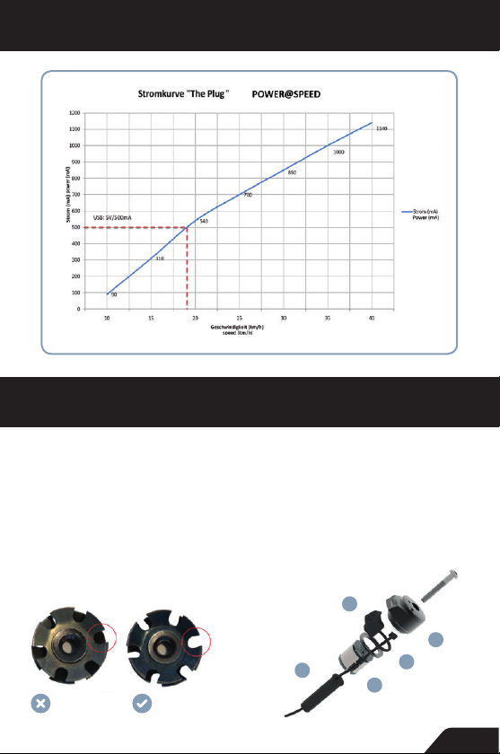
Verfügung gestellte Leistung können Sie auf nachfolgender Skala
ablesen.
The Plug w ird par allel zu Ihrer Beleucht ung ange schlossen d.h . das
Kabel wird ent weder direkt zum Dynamo geführt oder an einer frei
wählbaren Stelle par allel in das Lich tkabel eingeschlei ft. Bei Dire ktansc hluss an den Dyn amo beachten Sie bitte die Anweisungen des
Dynamoherstellers. Der Dynamoausgang ist in der Regel Wechselstrom u nd so muss keine P olarität b eachtet wer den. Bitte b eachten
Sie jedo ch, das s bei gle ichzei tigem Betrieb von Beleuchtung und
The Plug s owohl die Lad eleistung a ls auch die Lic htleistun g deutlich
abfäll t. Wir empfehl en daher eine “en tweder ode r” Anwendung , was
allerdings ein Licht mit An/Aus Schalterfunktion erfordert.
Die elek tris chen Bauteile v on The Plug sind gegen Feuchtigkeit geschüt zt. Je nach Einsatzgebiet k ann die USB Buchse im Laufe der
Zeit et was Korrosion (Flugrost) ansetzen, welc he die Funk tion aber
nicht beeintr ächtigt. Zur Reinigung können Sie ein Wat testäbchen
mit etwas Alkohol verwenden.
Bitte beachten Sie, dass unter Umständen die Verwendung eines
Pufferakkus notwendig ist. Nähere Infos erhalten Sie bei unseren
Service Mitarbeitern.
6 | 7
Page 5

GENERAL USE & FEATURES
The Plug c onsumes almo st no power if no device is conne cted. If 5V
(+/- ca. 0.2V) are supplied the g reen LED will turn on, regardless if
there is a device connected or not. If there is no device connected
and the in ternal voltage is too high (at high s peeds), the Plug sw itches off automatically.
The Plug h as been optimized to power devices that use USB standard as in terface. Please note that the actual use an d performance
of a device in combination with Th e Plug depends on the device’s
individual charging and operating characteristic. The Plug generally
provides a power inter face accor ding to USB-specifcation type A.
This means that t he USB wire 1 and 4 pro vide const ant power of 5V.
The Plug d oes onl y supply p ower once a cons tant output of 5V can
be supplied. The actual riding speed in order to provide 5V output
depends on your device’s individual charging and operating characteristic. Please check with your device’s manufacturer for compatibilit y and requirem ents. The fo llowing char t shows a basic ov erview
of output current depending on your spe ed. This, however, also depends o n the hub dynamo used.
The Plug h as been des igned for p arallel use w ith a light sy stem. Thus
there is no need t o dismount any cable after its initial in stallation.
Please also se e the light and dynamo manufacturer‘s instructions
for cable inst allation det ails. However please note that if The Plug
and a ligh t system are used at the same time, both light and The
Plug’s ou tput performance will dec rease based on the limi tation of
the hub dy namo. Thus we re commend to use “eithe r/or”.
The Plug ’s electronics have be en designed to be water-re sist ant.
How-ever depending on th e condi tions of use, the USB outlet might
show som e initial rust corrosion over time. This rust f ilm can be easily rem oved using a Q-tip w ith some alcoh ol.
Pleas e note: Never rotate the USB-Top-Cap (1) after inst allat ion, as
this might damag e the connect or cable.
Bitte beachten Sie, dass unter Umständen die Verwendung eines
Pufferakkus notwendig ist. Nähere Infos erhalten Sie bei unseren
Service Mitarbeitern.
8 | 9
Page 6
BEDIENUNG & FUNKTIONSWEISE | GENERAL USE & FEATURES
MONTAGE | INSTALLATION
Zum Einbau von The Plug benötigen Sie
Inbusschlüssel der Größe 4 und 5. Bitte
gehen Sie bei der Montage sorgfältig nach
den folgenden aufgeführten
eine unsachgemäße Montage zum Verlust
Ihrer Garantieansprüche führt.
Sie in jedem Fall, dass der Gabelschaft innen und außen entgratet ist.
ABBILDUNG 1 | FIGURE 1 ABBILDUNG 2 | FIGURE 2
Punkten vor, da
Beachten
For installation (Hex) Allen keys size 4 mm
and 5 mm are required. Please read carefully. If the instructions are not followed
carefully you might void your warranty! Also
make sure that the steer tube end is deburred on the inside and the outside.
5
Schlecht | bad
Gut | good
2
1
3
4
10 | 11
Page 7

MONTAGE
A Prüfung der Aheadkralle und Einfädeln des Anschlusskabels:
1. Je nach Typ der Aheadkralle können Sie das Kabel durch deren “Zacken” durchfädeln.
Beachten Sie hierzu Abb.1. Sollte ein Einfädeln nicht möglich sein, so gehen Sie zu Schritt
B.
2. Fädeln Sie das Anschlusskabel (5) von oben durch die “Krallen” der Aheadkralle. Beach-
ten Sie dabei, dass das Kabel nicht beschädigt wird. Weiter mit C.
B Alternativ zu A: Montieren des Expanders (4) mit integriertem Kabelkanal:
1. Setzen Sie den Aheadexpander mit dem seitlich “eingelegten” Kabel in den Gabelschaft
ein und ziehen Sie diese mit dem Inbusschlüssel fest. Beachten Sie, dass der Vorbau ca.
5 mm zum Gabelschaft übersteht. Verwenden Sie den beiliegenden Spacer (3) um den
Vorbau zu erhöhen.
2. Sollten Sie eine schon verbaute Kralle entfernen müssen, gehen Sie wie folgt vor:
Schlagen Sie die Aheadkralle durch das komplette Steuerrohr oder bohren Sie die Kralle
aus. Verwenden Sie dazu Bohrer der Durchmesser 6-8-10-11-12 mm und bohren Sie
nacheinander durch das Zentrum der Kralle bis Sie diese herausziehen können oder diese
in sich zusammenfällt.
C Verlegen des Kabels und Einstellung des Steuersatzspiels:
1. Führen Sie das Kabel (5) unten aus dem Steuerrohr und schließen Sie es entsprechend
(direkt bzw. eingeschleift) an die Spannungsquelle an. Beachten Sie hierzu auch die Informationen unterhalb der Stromkurve.
2. Stellen Sie den Steuersatz mit Ihrer bisherigen Aheadkappe ein. Fixieren Sie den Vorbau
und entfernen Sie danach die alte Steuersatzkappe.
D Montage des Ringes mit Dichtungsstopfen:
Legen Sie den Gummiring (2) mit USB-Schutzkappe auf den Alu-Spacer (3).
E Anschluss des Kopfes (1):
Schließen Sie den Stecker des Kopfes (1) an das Kabel (5) an, und setzen Sie den Kopf (1)
auf den Vorbau. Beachten Sie die Polung bzw. die Kennung des Steckers. Durch leichtes
Ziehen lässt sich die Verbindung wieder lösen. Führen Sie die M6 Steuersatzschraube zur
Fixierung des Kopfes ein. Beachten Sie unbedingt, dass das Kabel nicht von der Steuersatzschraube beschädigt wird. Auch darf der Kopf nach Montage nicht rotiert werden, um
ein Abreißen des Steckers zu vermeiden. Das Steuersatzspiel kann generell auch direkt
über den Kopf und dessen Schraube eingestellt werden.
12 | 13
Page 8

INSTALLATION
A Check of star-fangled nut and installation of cable:
The cable (5) can be wired through the “claws” of a standard star-fangled nut. Please
see Fig. 1 for details. Please make sure not to damage the cable! If this is not an option
continue with b.
B Alternative to a: Installation of expander nut with integrated cable channel (4).
1. Insert the expander nut (4) into the steer shaft with the cable(5) already inserted in the
channel. Tighten the expander nut using a Hex 5 Allen key. Make sure to leave a 5 mm gap
between the top of the steer shaft and the top of the stem. Please use the spacer supplied.
2. In case you already have a star-fangled nut installed you will need to remove it using
the following steps. You can either remove the star-fangled nut by forcing it out using a
hammer or by using a drilling technique. The drilling technique requires to repeat a drill
sequence through the center of the star-fangled nut by using a 6-8-10-11-12 mm drills one
after the other, until the star-fangled nut collapses.
C Connecting of cable and adjustment of headset:
1. Connect the cable (5) with the connector at the bottom of the Top Cap (1). If needed, the
cable can be disengaged using slight force.
2. Use your existing aheadset cap to adjust the headset. Torque the stem according to the
manufacturer’s specifications. Depending on your headset you might need a shorter M6
bolt.
3. There is no need to pay attention to polarity of the cables as the dynamo hub has AC
output. However please also see the light and dynamo manufacturer´s instructions for
cable installation details.
D Assembly of USB cover (2):
Slide the rubber O-ring of the USB cover assembly (2) over the
aluminium spacer (3).
E Top cap installation:
Install the top cap (1) like a regular ahead-set cap using the M6 bolt. NOTE: You can also
use the bolt of the top cap (1) to adjust the headset. In this case pay attention that the
cable does not get damaged!
14 | 15
Page 9

DE | EN
SUPERNOVA DESIGN GmbH & Co. KG
Industriestr. 26 | 79194 Gundelfingen
Germany
+49 (0) 761 600 629 - 0
[email protected]
www.supernova-lights.com
 Loading...