

Page 1
User Guide
SUPER NOVA 2 RGB 1
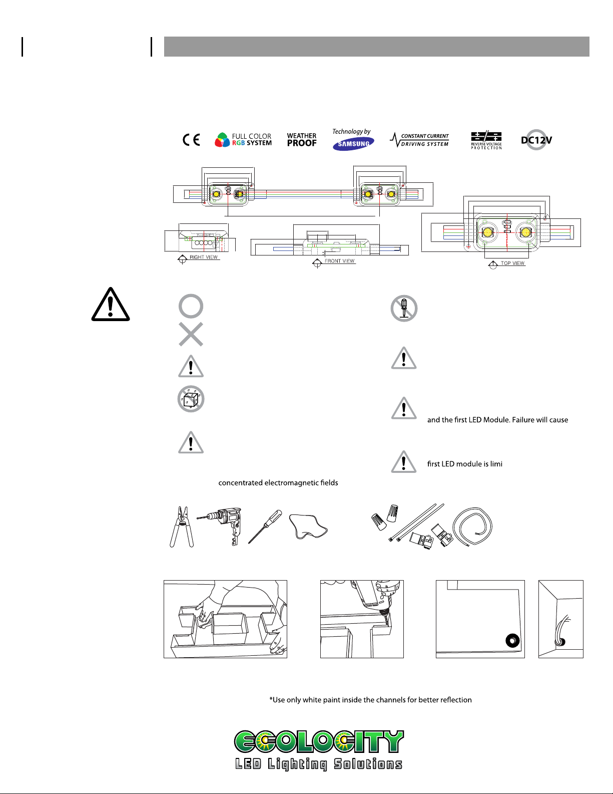
SPECIFICATIONS
PRECAUTIONS
ELECTRICAL THERMAL
Current dissipation : 55 mA
Power consumption : 0.6 W
Operating power : 12VDC Constant Voltage
Maximum serial connection : 50 modules
Electronic dimming control supported
PHYSICAL
0.28”
0.57”
0.33”
0.79”
1.78”
1.57”
1.38”
5.12 ”
0.21”
0.33”
0.23”
0.38”
0.43”
Cooling : Ambient air
Maximum operating temperature : 140˚F (60˚C)
Minimum operating temperature : -13˚F (-25˚C)
Maximum storage temperature : 140˚F (60˚C)
Minimum storage temperature : -22˚ F (-30˚C)
1.78”
1.57”
1.38”
0.79”
0.38”
1.78”
0.79”
0.38”
0.79”
0.07”
0.21”
1.78”
1.57”
1.38”
0.91”
Use precautions to avoid damages to the product or injuries of users. Any actions against following contents can cause serious
issues such as malfunction, electric shock, or burn.
Do not perform actions listed below:
DC12V
USE DC 12V INPUT ONLY!
- Alter or modify Modules
- Touch LED lamps with sharp objects
AC120V
DO NOT USE AC INPUT!
- Put glue or silicon over the LED lamps
Maximum driver quantity per serial
Do not cut or rejoin wires while product
is connected with live power source
connection is limited to available power supply
wattage, failure causes overload of current and
damages to the product
Avoid performing installation under rain
or high humidity and only install in
temperatures above 50˚F (10˚C) to allow for
better mounting tape adhesion
Do not use the product under any of the
Refer to ‘WIRE THICKNESS’ table to use proper
wire thickness between 12V power supply
dimmed output.
circumstances listed below:
- High temperature locations over 140˚F (60˚C)
- Spots with extreme moisture or dust
- Places that have corrosive gas or have highly
Cable length between power supply and the
ted. Refer to
‘CONNECTION WITH POWER SUPPLY’ on page 2
0.57”
0.28”
PREPARATION
Wire Stripper, Drill, Screw Driver, towel or rag.
PREPARE CHANNEL LETTERS
inside of letter using Rubbing Alcohol
for best adhesion of mounting tape
EcolocityLED.com
SUPPLIES REQUIREDTOOLS REQUIRED
Wire Nuts, Cable Ties, IDC Connectors, Wire (Optional : Screws)
2. Drill a hole for power wire1. Clean moisture , dust and oil from the
3. Use bushing to protect incoming wires
from sharp edge of Channel Letter
775-636-6060
Page 2

User Guide
SUPER NOVA 2 RGB 2
LAYOUT DENSITY
GUIDELINES
CONNECTION GUIDE
Use recommended length for pitch between each module to achieve optimum lighting output while maintaining lowest unit
cost. Failure or misplacing will cause dimmed spots or uneven appearance of light on the surface. 3 inches minimum depth.
RECOMMENDED PITCH PER DEPTH
3”
2.75
Start Modules at about 2
inches from edge of Letter
RECOMMENDED LAYOUT DENSITY PER CHANNEL WIDTH
Place one row
of Modules in
the center of Letter
Maximum driver quantity per serial connection is limited to 50. Using more quantity per run will cause overload from Power
Supply which damages all connected products. This will cause voltage drop and also dimmed lighting output.
4”- 5.5”
Place two rows
of Modules
4”to 4.5” apart
AC Input
Power Supply
4”
4”
5.5”- 8” 8” + 6”+ Circle
Place each row
of Modules
4”to 4.5” apart
Make sure that each run should have 50 modules at max in a serial connection
(end to end module connection) & should use another run in parallel to connect more.
Should use thicker wires which can take larger amount of current
than the amount transmitted from the power supply unit.
5”
4.75” 4.75”
Place each row
of Modules
4”to 4.5” apart
6”
Use 10% to 20% shorter
length between modules
than usual for a circular
arrangement
CONNECTION WITH
POWER SUPPLY
12VDC Output
CAUTION
Keep extension lead wires as short as possible.
RGB Controller
Refer to below table for specific length.
RGB Controller Type
4 Pin & 3 Loop cables
1st 2nd 49th 50th
(Common Anode)
Parallel Connection
1st 2nd 49th 50th
1st 2nd 49th 50th
SUPER NOVA 2 RGB - MO DULES PER WATTS OF POWER & EXTE NSION OF LE AD WIRES FROM POWER SUPPLY
Output (W)
Output (A)
Max Module Quantity
Recommended
Extension Wire
Maximum Length
(parallel)
(stranded)
(serial connect)
20W
1.7A
30 pcs
22AWG 22AWG 18AWG 18AWG
25FT (7.62M)
40W
3.4A
60 pcs
25FT (7.62M)
60W
5A
90 pcs
25 FT (7.62M)
120W
10A
180 pcs
25FT (7.62M)
*Maximum quantity for Super Nova 2 RGB is based on approximately 90% of specied capactiy of power supplies for
extended lifespan. Equip with protective box for outdoor use and the box should have ventilating holes.
EcolocityLED.com
775-636-6060
Page 3

User Guide
2nd 29th 30th
Parallel Connection
SUPER NOVA 2 RGB 3
INSTALLATION GUIDE
1. DETERMINE LAYOUT
Channel Depth
Refer to ‘LAYOUT DENSITY GUIDELINES’ on page 2 to
determine spacing and amount of LEDs required.
3. CAP ALL UNUSED WIRES
Stroke Width
Wire Nut
2. PEEL AND STICK
Remove 3M™ VHB™ tape on the back of modules and
attached to the surface.
CAUTION
When handling the module, avoid pressing
down directly on top of LED lamp
4. CONNECT WITH POWER SUPPLY
Power Supply
12VDC Output
Protect the wire ends of the strand of modules should
not be looped to create a closed circuit.
5. FIX MODULES PERMANENTLY
FASTENERS: If desired, modules can be secured
with #4 X 1/2” metal screws.
RGB Controller
1st
Using predetermined layout and LED placement
from step 1, divide channels into sections and
distribute each section to corresponding power
supplies.
CAUTION
Before connect with power supplies, check
polarity on every connections
EcolocityLED.com
775-636-6060
Page 4

User Guide
SUPER NOVA 2 RGB 4
TROUBLE SHOOTING
Entire sign or leg does not light
after complete installation.
Still does not light.
Still does not light.
Beginning of a leg lights, but the
entire leg does not light or lights
intermittently.
One module does not light, but
all others in the leg light.
All modules light, but some of
them are dimmed.
Dark spots or dimmed spots
occur.
Check connection from power supply lead to first module. Make sure polarity of connections
made at the power supply lead and any jumper wire is correct. Power supply outputs should
be connected red-to-red and white-to-white.
Check output voltage of power supply using a voltmeter. The output voltage should be
12VDC ± 0.5VDC. If there is no output voltage, have a licensed electrician check input
voltage. Make sure power supply is connected correctly and getting primary power. Probably
AC input wire is connected to ground terminal of power supply. If power supply is connected
properly and getting primary power and there is still no output voltage, try a dierent power
supply.
If power supply is getting primary power and the modules do not light, there may be a short
in the secondary wiring
The primary cause for a portion of a module leg not lighting or lighting intermittently is a
bad connection or reverse polarity connection between the modules that light and the
modules that don’t light. Check this connection.
Super Nova Modules are designed so if one fails it will not cause the entire sign or leg to go
out. If one module does not light, but all others in the leg do, replace the unlit module.
Check that each run has no more than the maximum number of modules. Also, check that the
type of extension wire from the power supply to the first module is correct. If wires are
not thick enough to transmit current from the power supply, this will cause a voltage drop
and will dim the modules at the end.
Channel depth is too low, or center distance between modules is too far. Refer to 'LAYOUT
DENSITY GUIDELINES' for more information.
. Check all connections and cap all loose wires.
Still has spots.
Covering acrylic is not intended for LED illumination. Use light diusing acrylic sheets which
are specially made for LED light source
.
EcolocityLED.com
775-636-6060
 Loading...