

Page 1
SBI-7127R-S6
Blade Module
User’s Manual
Revison 1.0
Page 2
SBI-7427R-T3 Blade Module User’s Manual
The information in this User’s Manual has been carefully reviewed and is believed to be accurate. The
vendor assumes no responsibility for any inaccuracies that may be contained in this document, makes no
commitment to update or to keep current the information in this manual, or to notify any person or
organization of the updates. P lease Note: For the most up-to-date version of this manual, please see
our web site at www.supermicro.com.
Super Micro Computer, Inc. ("Supermicro") reserves the right to make changes to the product described
in this manual at any time and without notice. This product, including software and documentation, is the
property of Supermicro and/or its licensors, and is supplied only under a license. Any u se or rep rodu ction
of this product is not allowed, except as expressly permitted by the terms of said license.
IN NO EVENT WILL SUPERMICRO BE LIABLE FOR DIRECT, INDIRECT, SPECIAL, INCIDENTAL,
SPECULATIVE OR CONSEQUENTIA L DAMAGES ARISING FROM THE USE OR INABILITY TO USE
THIS PRODUCT OR DOCUMENTATION, EVEN IF ADVISED OF THE POSSIBILITY OF SUCH
DAMAGES. IN PARTICULAR, SUPERMICRO SHALL NOT HAVE LIABILITY FOR ANY HARDWARE,
SOFTWARE, OR DATA STORED OR USED WITH THE PRODUCT, INCLUDING THE COSTS OF
REPAIRING, REPLACING, INTEGRATING, INSTALLING OR RECOVERING SUCH HARDWARE,
SOFTWARE, OR DATA.
Any disputes arising between manufacturer and customer shall be governe d by the laws of Santa Clara
County in the State of Californ i a, USA. The State of California, County of Sant a Clara shall be the
exclusive venue for the resolution of any such disputes. Super Micro's total liability for all claims will not
exceed the price paid for the hardware product.
FCC Statement: This equipment has been tested and found to comply with the limits for a Class A digital
device pursuant to Part 15 of the FCC Rules. These limits are designed to provide reasonable protection
against harmful interference when the equipment is operated in a commercial environment. This
equipment generates, uses, and can radiate radio frequency energy and, if not installed and used in
accordance with the manufacturer’s instruction manual, may cause harmful interference with radio
communications. Operation of this equipment in a residential area is likely to cause harmful interference,
in which case you will be required to correct the interference at your own expense.
California Best Management Practices Regulat i ons for Perchlorate Materials: This Perchlorate warning
applies only to products containing CR (Manganese Dioxide) Lithium coin cells. Perchlorate
Material-special handling may apply. See www.dtsc.ca.gov/hazardouswaste/perchlorate for further
details.
WARNING: HANDLING OF LEAD SOLDER MATERIALS USED IN THIS
PRODUCT MAY EXPOSE YOU TO LEAD, A CHEMICAL KNOWN TO THE
STATE OF CALIFORNIA TO CAUSE BIRTH DEFECTS AND OTHER
REPRODUCTIVE HARM.
Manual Revison 1.0
Release Date: January 7, 2013
Unless you request and receive written permission from Super Micro Computer, Inc., you may not copy
any part of this document.
Information in this document is subject to change without notice. Other products and companies referred
to herein are trademarks or registered trademarks of their respective companies or mark holders.
Copyright © 2012 by Super Micro Computer, Inc.
All rights reserved.
Printed in the United States of America
ii
Page 3

Preface
About this Manual
This manual is written for professional system integrators, Information Technology
professionals, service personnel and technicians. It provides information for the
installation and use of the Supermicro SuperBlade
module. Installation and maintenance should be performed by experienced
professionals only.
Manual Organization
Chapter 1: Introduction
The first chapter provides a checklist of the main components included with
SBI-7127R-S6 blade module and describes their main features.
Chapter 2: System Safety
You should familiarize yourself with this chapter for a general overview of safety
precautions that should be followed when installing and servicing SBI-7127R-S6 blade
module.
Chapter 3: Setup and Installation
Refer to this chapter for details on installing the SBI-7127R-S6 blade module into the
SuperBlade chassis. Other sections cover the installation and placement of memory
modules and the installation of hard disk drives into the blade module.
Chapter 4: Blade Module Features
This chapter coves features and component information about SBI-7127R-S6 blade
module. Included here are descriptions and information for mainboard components,
connectors, LEDs and other features of the blade module.
Chapter 5: BIOS
BIOS setup is covered in this chapter for SBI-7127R-S6 blade module.
Appendix A: BIOS POST Codes
BIOS POST Codes for SBI-7127R-S6 blade module are explained in this appendix.
®
system’s SBI-7127R-S6 blade
iii
Page 4

SBI-7427R-T3 Blade Module User’s Manual
Notes
iv
Page 5

Table of Contents
Chapter 1 Introduction.......................................................................1-1
1-1 Overview.............................................................................................1-1
1-2 Product Checklist of Typical Components.....................................1-1
1-3 Blade Module Features....................................................................1-2
Processors..............................................................................................1-2
Memory...................................................................................................1-2
Storage....................................................................................................1-3
RAID .......................................................................................................1-3
Density....................................................................................................1-3
1-4 Contacting Supermicro.....................................................................1-5
Chapter 2 Standardized Warning Statements.....................2-1
2-1 About Standardized Warning Statements......................................2-1
Warning Definition...................................................................................2-1
Installation Instructions ...........................................................................2-3
Circuit Breaker........................................................................................2-4
Power Disconnection Warning................................................................2-5
Equipment Installation................................................... ..........................2-6
Restricted Area.......................................................................................2-7
Battery Handling .....................................................................................2-9
Redundant Power Supplies ..................................................................2-10
Backplane Voltage................................................................................2-11
Comply with Local and National Electrical Codes.................................2-12
Product Disposal...................................................................................2-13
Hot Swap Fan Warning .........................................................................2-14
Power Cable and AC Adapter ..............................................................2-15
Chapter 3 Setup and Installation.................................................3-1
3-1 Overview.............................................................................................3-1
3-2 Installing Blade Modules..................................................................3-1
Powering Up a Blade Unit.......................................................................3-1
Powering Down a Blade Unit ..................................................................3-1
Removing a Blade Unit from the Enclosure............................................3-2
Removing/Replacing the Blade Cover....................................................3-2
Installing a Blade Unit into the Enclosure ...............................................3-2
3-3 Processor Installation .......................................................................3-4
v
Page 6

Table of Contents
3-4 Onboard Battery Installation............................................................3-9
3-5 Memory Installation...........................................................................3-9
Populating Memory Slots........................................................................3-9
DIMM Installation..................................................................................3-11
3-6 Hard Disk Drive Installation...........................................................3-12
3-7 Installing the Operating System....................................................3-13
Installing with an External USB CD-ROM Drive....................................3-13
Installing via PXE Boot..........................................................................3-14
Installing via Virtual Media (Drive Redirection) .....................................3-14
3-8 Management Software...................................................................3-15
3-9 Configuring and Setting up RAID.................................................3-15
Chapter 4 Blade Module Features..............................................4-1
4-1 Control Panel.....................................................................................4-2
Power Button ..........................................................................................4-3
KVM Button.............................................................................................4-3
LED Indicators ........................................................................................4-3
KVM Connector.......................................................................................4-3
4-2 Mainboard...........................................................................................4-4
Jumpers..................................................................................................4-6
CMOS Clear............................................................................................4-6
4-3 Blade Unit Components...................................................................4-7
Memory Support .....................................................................................4-8
Hard Disk Drives.....................................................................................4-8
Chapter 5 BIOS.......................................................................................5-1
5-1 Introduction.........................................................................................5-1
System BIOS ..........................................................................................5-1
How To Change the Configuration Data .................................................5-1
Starting the Setup Utilit y.................... .. ... .......................................... ... ... .5-1
5-2 BIOS Updates....................................................................................5-2
Flashing BIOS.........................................................................................5-2
5-3 Running Setup...................................................................................5-3
5-4 Main BIOS Setup...............................................................................5-4
5-5 Advanced Setup................................................................................5-5
5-6 Event Logs Setup............................................................................5-14
5-7 IPMI Setup........................................................................................5-15
5-8 Boot...................................................................................................5-16
vi
Page 7

5-9 Security.............................................................................................5-16
5-10 Save & Exit.....................................................................................5-17
Appendix A BIOS POST Codes....................................................A-1
A-1 BIOS POST Messages....................................................................A-1
A-2 BIOS POST Codes...........................................................................A-3
Recoverable POST Errors......................................... ... ..........................A-4
Terminal POST Errors.............................................................. ...............A-4
:
vii
Page 8

SBI-7427R-T3 Blade Module User’s Manual
Notes
viii
Page 9

Chapter 1
Introduction
1-1 Overview
This user’s manual covers the SBI-7127R-S6 blade module. This blade module is a
compact self-contained server that connects into a pre-cabled enclosure that provides
power, cooling, management and networking functions. One enclosure for the
SBI-7127R-S6 blade module can hold ten blade units.
In this manual, “blade system” refers to the entire system (including the enclosure and
blades units), “blade” or “blade unit” refers to a single blade module and “blade
enclosure” is the chassis that the blades, power supplies and modules are housed
within.
Please refer to our web site for information on operating systems that have been
certified for use with the SuperBlade (www.supermicro.com/products/superblade/).
Note: A complete list of safety warnings is provided on the Supermicro web site at
http://www.supermicro.com/about/policies/safety_information.cfm.
1-2 Product Checklist of Typical Components
Your blade module ships with its B9DR7 mainboard already installed in its chassis.
Memory, hard disk drives and the CPU must all be installed by the user after shipment.
See Chapter 3: "Setup and Installation" on page 3-1 for details on installation of these
components.
Aside from the blade module unit itself, the following optional Mezzanine add-on cards
(with 10GbE or Infiniband Switch) may be ordered for your blade module:
• AOC-XEH-iN2
• AOC-IBH-XDD
• AOC-IBH-XQD
• AOC-IBH-XQS
• AOC-IBH-XDS
See the Supermicro website and the SuperBlade Network Modules User’s Manual on
your SuperBlade system’s CD-ROM for more details on these add-on cards.
1-1
Page 10
SBI-7127R-S6 Blade Module User’s Manual
1-3 Blade Module Features
Table 1-1 lists the main features of the SBI-7127R-S6 blade module. See the
proceeding section for components typically included in a blade system and other
optional components. Specific details for the SBI-7127R-S6 blade module are found in
Chapter 4: "Blade Module Features" on page 4-1.
Table 1-1. SBI-7127R-S6 Blade Module Specification Features
Mainboard
Processors
FSB Speed QPI up to 8 GT/s
Chipset Intel C602J
Graphics Controller Integrated Matrox G200 Graphics
BIOS 16 Mb SPI Flash EEPROM with AMI® BIOS
Memory Capacity
HDD Controller LSI™ 2208® RAID controller
Hard Drive Bays Includes six hot-swap drive bays for 2.5" SATA/SAS/SSD disk drives
B9DR7 (proprietary form factor)
Chassis Dimensions (HxWxD): 1 1.32 " x 1.67" x 18. 9" ( 288mm x 42.4 mm x
480mm)
Eight/six/four core Intel™ Xeon® E5-2600 series 2011- pin processors.
Please refer to our web site for a complete listing of supported processors.
Supports up to 512 GB of RDIMM and 128 GB UDIMM SDRAM memory of
DDR3 1600/1333/1066/800 MHz speed and 32GB, 16GB, 8GB, 4GB, 2GB
and 1GB size in sixteen (16) 240-pin DIMM sockets
Processors
The SBI-7127R-S6 blade module supports dual 201 1-pin Socket R (LGA 2011) E5-2600
series processors.
Refer to the Supermicro web site for a complete listing of supported processors (http://
www.supermicro.com/products/superblade). Please note that you will need to check the
detailed specifications of a particular blade module for a list of the CPUs it supports.
Details on installation of the processor into the SBI-7127R-S6 blade module are found in
Chapter 3: "Setup and Installation" on page 3-1.
Memory
Both the SBI-7127R-S6 blade module have sixteen (16) 240-pin DIMM sockets that can
support up to 512 GB RDIMM or 128 GB UDIMM of DDR3 1600/1333/1066/800 MHz
speed, 32GB, 16GB, 8GB, 4GB, 2GB and 1GB size SDRAM memory. Memory is
interleaved, which requires modules of the same size and speed to be installed in
groups (of two or three).
Please refer to the Supermicro web site for a list of supported memory
(www.supermicro.com/products/superblade). The detailed specifications for a blade
module will contain a link to a list of recommended memory sizes and manufacturers.
1-2
Page 11

Chapter 1: Introduction
Details on installation of memory modules into the SBI-7127R-S6 blade module are
found in Chapter 3: "Setup and Installation" on page 3-1.
Storage
The SBI-7127R-S6 blade module can have six 2.5" SATA/SAS/SSD hard disk drives in
front-mounted easy removable carriers. See Chapter 3: "Setup and Installation" on
page 3-1 for storage installation details.
RAID
Each SBI-7127R-S6 blade module supports up to three hard drives, which may be used
to create a RAID 0, 1, 5 and 10 (Windows), RAID 0, 1 and 10 (Linux) or RAID 0, 1, 5, 6,
10 and 50 SAS array. For RAID setup use the procedure below . Thi s blade’s BIOS has a
RAID utility available in its setup.
With two or hard drives per blade, the following RAID configurations are supported:
• RAID 0 (Data Striping): this writes data in parallel, interleaved (“striped”) sections on
two hard drives. Data transfer rate is doubled over using a single disk.
• RAID1 (Data Mirroring): an identical data image from one drive is copied to another
drive. The second drive must be the same size or larger than the first drive.
• Enhanced RAID 5 or RAID 10 (Data Mirroring): as RAID1 with data mirrored from
one or more disks to one or more disks of a second, larger size. You can couple the
disks from the source to create a virtual volume and use one or more disks of a
second, larger size to provide a single larger volume (or multiple larger volumes)
that serve as the mirroring drive or drives for the array.
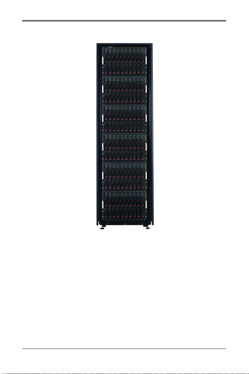
Density
A maximum of ten blade modules may be installed into a single blade enclosure. Each
blade enclosure is a 7U form factor, so a standard 42U rack may accommodate up to six
enclosures with 60 blade modules, or the equivalent of 60 1U servers. With the inclusion
of six CMM modules, twelve Gigabit Ethernet switches and six InfiniBand switches, this
would occupy up to 84U space in a conventional 1U server configuration.
Figure 1-1 displays a view of a full rack with six blade enclosures in it, each with ten
blades to an enclosure.
1-3
Page 12
SBI-7127R-S6 Blade Module User’s Manual
Figure 1-1. Full Rack of Blade Enclosures and Blade Servers
1-4
Page 13

1-4 Contacting Supermicro
Headquarters
Address: Super Micro Computer, Inc.
980 Rock Ave.
San Jose, CA 95131 U.S.A.
Tel: +1 (408) 503-8000
Fax: +1 (408) 503-8008
Email:
Web Site: www.supermicro.com
Europe
Address: Super Micro Computer B.V.
Tel: +31 (0) 73-6400390
Fax: +31 (0) 73-6416525
Email:
Asia-Pacific
Address: Super Micro Computer, Inc.
Tel: +886-(2) 8226-3990
Fax: +886-(2) 8226-3991
Web Site: www.supermicro.com.tw
Technical Support:
Email: support@supermicro.com.tw
Tel: +886-(2) 8226-5990
marketing@supermicro.com (General Information)
support@supermicro.com (Technical Support)
Het Sterrenbeeld 28, 5215 ML
‘s-Hertogenbosch, The Netherlands
sales@supermicro.nl (General Information)
support@supermicro.nl (Technical Support)
rma@supermicro.nl (Customer Support)
4F, No. 232-1, Liancheng Rd.
Chung-Ho 235, Taipei County
Taiwan, R.O.C.
Chapter 1: Introduction
1-5
Page 14

SBI-7127R-S6 Blade Module User’s Manual
Notes
1-6
Page 15
Chapter 2
Standardized Warning Statements
2-1 About Standardized Warning Statements
The following statements are industry standard warnings, provided to warn the user of
situations which have the potential for bodily injury. Should you have questions or
experience difficulty, cont act Supermicro's Technical Support department for assistance.
Only certified technicians should attempt to install or configure components.
Read this appendix in its entirety before installing or configuring components in the
Supermicro chassis
These warnings may also be found on our web site at http://
www.supermicro.com/about/policies/safety_information.cfm.
Warning Definition
Warning!
This warning symbol means danger. You are in a situation that could cause
bodily injury. Before you work on any equipment, be aware of the hazards
involved with electrical circuitry and be familiar with standard practices for preventing
accidents.
警告の定義
この警告サインは危険を意味します。
人身事故につながる可能性がありますので、いずれの機器でも動作させる前に、
電気回路に含まれる危険性に注意して、標準的な事故防止策に精通して下さい。
此警告符号代表危险。
您正处于可能受到严重伤害的工作环境中。在您使用设备开始工作之前,必须充分意识到
触电的危险,并熟练掌握防止事故发生的标准工作程序。请根据每项警告结尾的声明号码
找到此设备的安全性警告说明的翻译文本。
此警告符號代表危險。
您正處於可能身體可能會受損傷的工作環境中。在您使用任何設備之前,請注意觸電的危
險,並且要熟悉預防事故發生的標準工作程序。請依照每一注意事項後的號碼找到相關的
翻譯說明內容。
2-1
Page 16

SBI-7127R-SH Blade Module User’s Manual
ןןונקת תורהצהאהרהז
ןה תואבה תורהצהא ינפמ שמתשמה תא ריהזהל תנמ לע ,היישעתה ינקת יפ לע תורהז הלבח
ה וא תולאש שיו הדימב .תירשפא תיזיפי ,יהשלכ היעבב תולקתרוציל שי הכימת תקלחמ םע רשק
רידגהל וא ןיקתהל םיאשר דבלב םיכמסומ םיאנכט .ורקימרפוס לש תינכט תאה .םיביכר
אורקל שי .ורקימרפוס יזראמב םיביכרה תרדגה וא תנקתה ינפל ואולמב חפסנה תא
. ﻲﻓ ﻚﻧﺍ ﻥﺃ ﻦﻜﻤﻳ ﺔﻟﺎﺣ ﻲﻓ ﺐﺒﺴﺘﺗ ﺔﺑﺎﺻﺍ ﺔﻳﺪﺴﺟ ﺰﻣﺮﻟﺍ ﺍﺬﻫ ﻲﻨﻌﻳ ﺮﻄﺧ !ﺮﻳﺬﺤﺗ
ﻥﺃ ﻞﺒﻗ ﻱﺃ ﻰﻠﻋ ﻞﻤﻌﺗ ﺕﺍﺪﻌﻣ،ﻛﻢﻠﻋ ﻰﻠﻋ ﻦ ﻦﻋ ﺔﻤﺟﺎﻨﻟﺍ ﺮﻁﺎﺨﻤﻟﺎﺑ ﺮﺋﺍﻭﺪﻟﺍ
ﺔﻴﺋﺎﺑﺮﻬﻜﻟﺍ
ﻛﻭﺔﻳﺍﺭﺩ ﻰﻠﻋ ﻦ ﺭﺎﻤﻤﻟﺎﺑﺕﺎﺳ ﺔﻴﺋﺎﻗﻮﻟﺍ ﻟ ﻊﻨﻤﻉﻮﻗﻭ ﻱﺃﺙﺩﺍﻮﺣ
ﻢﻗﺭ ﻡﺪﺨﺘﺳﺍ ﻥﺎﻴﺒﻟﺍ ﺹﻮﺼﻨﻤﻟﺍ ﺔﻳﺎﻬﻧ ﻲﻓ ﺮﻳﺬﺤﺗ ﻞﻛ ﺭﻮﺜﻌﻠﻟ ﺎﻬﺘﻤﺟﺮﺗ
Warnung
WICHTIGE SICHERHEITSHINWEISE
Dieses Warnsymbol bedeutet Gefahr. Sie befinden sich in einer Situation, die zu
Verletzungen führen kann. Machen Sie sich vor der Arbeit mit Geräten mit den Gefahren
elektrischer Schaltungen und den üblichen Verfahren zur Vorbeugung vor Unfällen
vertraut. Suchen Sie mit der am Ende jeder Warnung angegebenen
Anweisungsnummer nach der jeweiligen Übersetzung in den übersetzten
Sicherheitshinweisen, die zusammen mit diesem Gerät ausgeliefert wurden.
BEWAHREN SIE DIESE HINWEISE GUT AUF.
INSTRUCCIONES IMPORTANTES DE SEGURIDAD
Este símbolo de aviso indica peligro. Existe riesgo para su integridad física. Antes de
manipular cualquier equipo, considere los riesgos de la corriente eléctrica y
familiarícese con los procedimientos estándar de prevención de accidentes. Al final de
cada advertencia encontrará el número que le ayudará a encontrar el texto traducido en
el apartado de traducciones que acompaña a este dispositivo.
GUARDE ESTAS INSTRUCCIONES.
IMPORTANTES INFORMATIONS DE SÉCURITÉ
Ce symbole d'avertissement indique un danger. Vous vous trouvez dans une situation
pouvant entraîner des blessures ou des dommages corporels. Avant de travailler sur un
équipement, soyez conscient des dangers liés aux circuits électriques et
familiarisez-vous avec les procédures couramment utilisées pour éviter les accidents.
Pour prendre connaissance des traductions des avertissements figurant dans les
consignes de sécurité traduites qui accompagnent cet appareil, référez-vous au numéro
de l'instruction situé à la fin de chaque avertissement.
CONSERVEZ CES INFORMATIONS.
안전을 위한 주의사항
2-2
Page 17

Chapter 2: Standardized Warning Statements
경고 !
이 경고 기호는 위험이 있음을 알려 줍니다 . 작업자의 신체에 부상을 야기 할 수 있는
상태에 있게 됩니다 . 모든 장비에 대한 작업을 수행하기 전에 전기회로와 관련된 위험
요소들을 확인하시고 사전에 사고를 방지할 수 있도록 표준 작업절차를 준수해 주시기
바랍니다 .
해당 번역문을 찾기 위해 각 경고의 마지막 부분에 제공된 경고문 번호를 참조하십시오
BELANGRIJKE VEILIGHEIDSINSTRUCTIES
Dit waarschuwings symbool betekent gevaar. U verkeert in een situatie die lichamelijk
letsel kan veroorzaken. Voordat u aan enige apparatuur gaat werken, dient u zich
bewust te zijn van de bij een elektrische installatie betrokken risico's en dient u op de
hoogte te zijn van de standaard procedures om ongelukken te voorkomen. Gebruik de
nummers aan het eind van elke waarschuwing om deze te herleiden naar de
desbetreffende locatie.
BEWAAR DEZE INSTRUCTIES
Installation Instructions
Warning!
Read the installation instructions before connecting the system to the power
source.
設置手順書
システムを電源に接続する前に、設置手順書をお読み下さい。
警告
将此系统连接电源前 , 请先阅读安装说明。
警告
將系統與電源連接前,請先閱讀安裝說明。
Warnung
Vor dem Anschließen des Systems an die Stromquelle die Installationsanweisungen
lesen.
¡Advertencia!
Lea las instrucciones de instalación antes de conectar el sistema a la red de
alimentación.
Attention
Avant de brancher le système sur la source d'alimentation, consulter les directives
d'installation.
2-3
Page 18

SBI-7127R-SH Blade Module User’s Manual
אורקל שי רוקמל תכרעמה רוביח ינפל הנקתה תוארוה תאחתמ.
ﻟﺍ ﺕﺍﺩﺎﺷﺭﺇ ﺮﻗﺍﺐﻴﻛﺮﺘ ﻞﻴﺻﻮﺗ ﻞﺒﻗ ﻰﻟﺇ ﻡﺎﻈﻨﻟﺍ ﺔﻗﺎﻄﻠﻟ ﺭﺪﺼﻣ
לע ךמתסמ הז רצומנגהה תעינמל םינבמב תנקתומה יכ אדוול שי .ילמשח רצק
רצקה ינפמ ןגמה רישכמה ילמשחהמ רתוי אל אוה-
250 V, 20 A
시스템을 전원에 연결하기 전에 설치 안내를 읽어주십시오 .
Waarschuwing
Raadpleeg de installatie-instructies voordat u het systeem op de voedingsbron aansluit.
Circuit Breaker
Warning!
This product relies on the building's installation for short-circuit (overcurrent)
protection. Ensure that the protective device is rated not greater than: 250 V,
20 A.
サーキット・ブレーカー
この製品は、短絡(過電流)保護装置がある建物での設置を前提としています。
保護装置の定格が 250V、20A を超えないことを確認下さい。
警告
此产品的短路 ( 过载电流 ) 保护由建筑物的供电系统提供 , 确保短路保护设备的额定电流
不大于 250V,20A。
警告
此產品的短路 ( 過載電流 ) 保護由建築物的供電系統提供 , 確保短路保護設備的額定電
流不大於 250V,20A。
Warnung
Dieses Produkt ist darauf angewiesen, dass im Gebäude ein Kurzschluss- bzw.
Überstromschutz installiert ist. Stellen Sie sicher, dass der Nennwert der
Schutzvorrichtung nicht mehr als: 250 V, 20 A beträgt.
¡Advertencia!
Este equipo utiliza el sistema de protección contra cortocircuitos (o sobrecorrientes) del
edificio. Asegúrese de que el dispositivo de protección no sea superior a: 250 V, 20 A.
Attention
Pour ce qui est de la protection contre les courts-circuits (surtension), ce produit dépend
de l'installation électrique du local. Vérifiez que le courant nominal du dispositif de
protection n'est pas supérieur à :250 V, 20 A.
2-4
Page 19
Chapter 2: Standardized Warning Statements
ﺞﺘﻨﻤﻟﺍ ﺍﺬﻫ ﻰﻠﻋ ﺪﻤﺘﻌﻳ ﺕﺍﺪﻌﻣ ﺔﻳﺎﻤﺤﻟﺍ ﺓﺮﻴﺼﻘﻟﺍﺮﺋﺍﻭﺪﻟﺍ ﻦﻣ ﺎﻬﺘﻴﺒﺜﺗ ﻢﺗ ﻲﺘﻟﺍ ﻲﻓ
ﻰﻨﺒﻤﻟﺍ
20A, 250V : ﻦﻣ ﺪﻛﺄﺗ ﻥﺃ ﻢﻴﻴﻘﺗ ﺯﺎﻬﺠﻟﺍ ﻟﺍﻲﺋﺎﻗﻮ ﺲﻴﻟ ﻦﻣ ﺮﺜﻛﺃ
경고 !
이 제품은 전원의 단락 ( 과전류 ) 방지에 대해서 전적으로 건물의 관련 설비에 의존합니
다 . 보호장치의 정격이 반드시 250V( 볼트 ), 20A( 암페어 ) 를 초과하지 않도록 해야
합니다 .
Waarschuwing
Dit product is afhankelijk van de kortsluitbeveiliging (overspanning) van uw electrische
installatie. Controleer of het beveiligde aparaat niet groter gedimensioneerd is dan
220V, 20A.
Power Disconnection Warning
Warning!
The system must be disconnected from all sources of power and the power
interior to install or remove system components.
電源切断の警告
システムコンポーネントの取り付けまたは取り外しのために、シャーシー内部にアクセ
スするには、
cord removed from the power supply module(s) before accessing the chassis
システムの電源はすべてのソースから切断され、電源コードは電源モジュールから取り
外す必要があります。
警告
在你打开机箱并安装或移除内部器件前 , 必须将系统完全断电 , 并移除电源线。
警告
在您打開機殼安裝或移除內部元件前,必須將系統完全斷電,並移除電源線。
Warnung
Das System muss von allen Quellen der Energie und vom Netzanschlusskabel getrennt
sein, das von den Spg.Versorgungsteilmodulen entfernt wird, bevor es auf den
Chassisinnenraum zurückgreift, um Systemsbestandteile anzubringen oder zu
entfernen.
2-5
Page 20

SBI-7127R-SH Blade Module User’s Manual
יילמשח קותינ ינפמ הרהזא
!הרהזא
למשחה תורוקמ לכמ תכרעמה תא קתנל שי ריסהל שיו קפסהמ ילמשחה לבכ תא
נקתה ךרוצל זראמה לש ימינפה קלחל השיג ינפלת רסה ואת .םיביכר
ﻞﺼﻓ ﺐﺠﻳ ﻡﺎﻈﻨﻟﺍ ﻊﻴﻤﺟ ﻦﻣﺭﺩﺎﺼﻣ ﺔﻗﺎﻄﻟﺍ ﺔﻟﺍﺯﺇﻭ ءﺎﺑﺮﻬﻜﻟﺍ ﻚﻠﺳ ﻦﻣ ﺓﺪﺣﻭ ﺩﺍﺪﻣﺍ
ﺔﻗﺎﻄﻟﺍ ﻞﺒﻗ
ﻰﻟﺇ ﻝﻮﺻﻮﻟﺍ ﺔﻴﻠﺧﺍﺪﻟﺍ ﻖﻁﺎﻨﻤﻟﺍ ﻟﻞﻜﻴﻬﻠ ﺔﻟﺍﺯﺇ ﻭﺃ ﺖﻴﺒﺜﺘﻟ ﺕﺎﻧﻮﻜﻣ ﺯﺎﻬﺠﻟﺍ
¡Advertencia!
El sistema debe ser disconnected de todas las fuentes de energía y del cable eléctrico
quitado de los módulos de fuente de alimentación antes de tener acceso el interior del
chasis para instalar o para quitar componentes de sistema.
Attention
Le système doit être débranché de toutes les sources de puissance ainsi que de son
cordon d'alimentation secteur avant d'accéder à l'intérieur du chassis pour installer ou
enlever des composants de systéme.
경고 !
시스템에 부품들을 장착하거나 제거하기 위해서는 섀시 내부에 접근하기 전에 반드시
전원 공급장치로부터 연결되어있는 모든 전원과 전기코드를 분리해주어야 합니다 .
Waarschuwing
Voordat u toegang neemt tot het binnenwerk van de behuizing voor het installeren of
verwijderen van systeem onderdelen, dient u alle spanningsbronnen en alle
stroomkabels aangesloten op de voeding(en) van de behuizing te verwijderen.
Equipment Installation
Warning!
Only trained and qualified personnel should be allowed to install, replace, or
service this equipment.
機器の設置
トレーニングを受け認定された人だけがこの装置の設置、交換、またはサービスを許
可されています。
警告
只有经过培训且具有资格的人员才能进行此设备的安装、更换和维修。
警告
只有經過受訓且具資格人員才可安裝、更換與維修此設備。
2-6
Page 21
Chapter 2: Standardized Warning Statements
!הרהזא
שר דבלב ךמסומ תווצתא ףילחהל ,ןיקתהל יא .דויצה רובע תוריש תתל וא דויצה
ﻦﻴﺑﺭﺪﻤﻟﺍﻭ ﻭ ﺐﻴﻛﺮﺘﻟﻝﺍﺪﺒﺘﺳﺍ ﻭﺃ ﺔﻣﺪﺧ ﺯﺎﻬﺠﻟﺍ ﺍﺬﻫ ﺢﻤﺴﻳ ﻥﺃ ﺐﺠﻳ ﻂﻘﻓ ﻦﻴﻠﻫﺆﻤﻟﺍ ﻦﻴﻔﻅﻮﻤﻠﻟ
Warnung
Das Installieren, Ersetzen oder Bedienen dieser Ausrüstung sollte nur geschultem,
qualifiziertem Personal gestattet werden.
¡Advertencia!
Solamente el personal calificado debe instalar, reemplazar o utilizar este equipo.
Attention
Il est vivement recommandé de confier l'installation, le remplacement et la maintenance
de ces équipements à des personnels qualifiés et expérimentés.
경고 !
훈련을 받고 공인된 기술자만이 이 장비의 설치 , 교체 또는 서비스를 수행할 수 있습니
다.
Waarschuwing
Deze apparatuur mag alleen worden geïnstalleerd, vervangen of hersteld door
geschoold en gekwalificeerd personeel.
Restricted Area
Warning!
This unit is intended for installation in restricted access areas. A restricted
access area can be accessed only through the use of a special tool, lock and
key, or other means of security. (This warning does not apply to workstations).
アクセス制限区域
このユニットは、アクセス制限区域に設置されることを想定しています。
アクセス制限区域は、特別なツール、鍵と錠前、その他のセキュリティの手段を用い
てのみ出入りが可能です。
警告
此部件应安装在限制进出的场所,限制进出的场所指只能通过使用特殊工具、锁和钥匙或
其它安全手段进出的场所。
警告
此裝置僅限安裝於進出管制區域,進出管制區域係指僅能以特殊工具、鎖頭及鑰匙或其
他安全方式才能進入的區域。
2-7
Page 22

SBI-7127R-SH Blade Module User’s Manual
תתלבגומ השיג םע רוזא
!הרהזא
תרזעב תנתינ השיגה .השיג תלבגה םהב שיש םירוזאב הדיחיה תא ןיקתהל שי
.('דכו לוענמ ,חתפמ) דבלב החטבא ילכ
. ﺺﻴﺼﺨﺗ ﺓﺪﺣﻮﻟﺍ ﻩﺬﻫ ﻲﻓ ﺎﻬﺒﻴﻛﺮﺘﻟ ﻖﻁﺎﻨﻣ ﺓﺭﻮﻈﺤﻣ ﻢﺗ
ﺻﻮﻟﺍ ﻦﻜﻤﻳﻰﻟﺇ ﻝﻮ ﺔﻘﻄﻨﻣ ﺓﺭﻮﻈﺤﻣ ﻂﻘﻓ ﻡﺍﺪﺨﺘﺳﺍ ﻝﻼﺧ ﻦﻣ ،ﺔﺻﺎﺧ ﺓﺍﺩﺃ
ﻭﺃ ﻱﺃ ﻼﻟ ﻯﺮﺧﺃ ﺔﻠﻴﺳﻭﻥﺎﻣﻷ ﺡﺎﺘﻔﻣﻭ ﻞﻔﻗ
Warnung
Diese Einheit ist zur Installation in Bereichen mit beschränktem Zutritt vorgesehen. Der
Zutritt zu derartigen Bereichen ist nur mit einem Spezialwerkzeug, Schloss und
Schlüssel oder einer sonstigen Sicherheitsvorkehrung möglich.
¡Advertencia!
Esta unidad ha sido diseñada para instalación en áreas de acceso restringido. Sólo
puede obtenerse acceso a una de estas áreas mediante la utilización de una
herramienta especial, cerradura con llave u otro medio de seguridad.
Attention
Cet appareil doit être installée dans des zones d'accès réservés. L'accès à une zone
d'accès réservé n'est possible qu'en utilisant un outil spécial, un mécanisme de
verrouillage et une clé, ou tout autre moyen de sécurité.
경고 !
이 장치는 접근이 제한된 구역에 설치하도록 되어있습니다 . 특수도구 , 잠금 장치 및 키
, 또는 기타 보안 수단을 통해서만 접근 제한 구역에 들어갈 수 있습니다 .
Waarschuwing
Dit apparaat is bedoeld voor installatie in gebieden met een beperkte toegang. Toegang
tot dergelijke gebieden kunnen alleen verkregen worden door gebruik te maken van
speciaal gereedschap, slot en sleutel of andere veiligheidsmaatregelen.
2-8
Page 23

Chapter 2: Standardized Warning Statements
!הרהזא
תנכס תמייקץוציפ .הניקת אל ךרדב הפלחוהו הדימב הללוסה לש ףילחהל שי
גוסב הללוסה תא מ םאותה תרבחלמומ ןרציתצ.
תוללוסה קוליס תושמושמה עצבל שי .ןרציה תוארוה יפל
ﺮﻄﺧ ﻙﺎﻨﻫ ﻦﻣ ﻝﺍﺪﺒﺘﺳﺍ ﺔﻟﺎﺣ ﻲﻓ ﺭﺎﺠﻔﻧﺍ ﺔﻳﺭﺎﻄﺒﻟﺍ ﺔﺤﻴﺤﺻ ﺮﻴﻏ ﺔﻘﻳﺮﻄﺑ ﻚﻴﻠﻌﻓ
ﺔﻳﺭﺎﻄﺒﻟﺍ ﻝﺍﺪﺒﺘﺳﺍ
ﻂﻘﻓ ﻉﻮﻨﻟﺍ ﺲﻔﻨﺑ ﺎﻬﻟﺩﺎﻌﻳ ﺎﻣ ﻭﺃ ﺎﻤﻛﺖﺻﻭﺃ ﺔﻌﻨﺼﻤﻟﺍ ﺔﻛﺮﺸﻟﺍ ﻪﺑ
ﺕﺎﻳﺭﺎﻄﺒﻟﺍ ﻦﻣ ﺺﻠﺨﺗ ﻟ ﺎﻘﻓﻭ ﺔﻠﻤﻌﺘﺴﻤﻟﺍﺔﻌﻧﺎﺼﻟﺍ ﺔﻛﺮﺸﻟﺍ ﺕﺎﻤﻴﻠﻌﺘ
Battery Handling
Warning!
There is the danger of explosion if the battery is replaced incorrectly. Replace
the battery only with the same or equivalent type recommended by the
manufacturer. Dispose of used batteries according to the manufacturer's instructions.
電池の取り扱い
電池交換が正しく行われなかった場合、破裂の危険性があります。交換する電池は
メーカーが推奨する型、または同等のものを使用下さい。使用済電池は製造元の指示
に従って処分して下さい。
警告
电池更换不当会有爆炸危险。请只使用同类电池或制造商推荐的功能相当的电池更换原有
电池。请按制造商的说明处理废旧电池。
警告
電池更換不當會有爆炸危險。請使用製造商建議之相同或功能相當的電池更換原有電
池。請按照製造商的說明指示處理廢棄舊電池。
Warnung
Bei Einsetzen einer falschen Batterie besteht Explosionsgefahr. Ersetzen Sie die
Batterie nur durch den gleichen oder vom Hersteller empfohlenen Batterietyp.
Entsorgen Sie die benutzten Batterien nach den Anweisungen des Herstellers.
Attention
Danger d'explosion si la pile n'est pas remplacée correctement. Ne la remplacer que par
une pile de type semblable ou équivalent, recommandée par le fabricant. Jeter les piles
usagées conformément aux instructions du fabricant.
¡Advertencia!
Existe peligro de explosión si la batería se reemplaza de manera incorrecta.
Reemplazar la batería exclusivamente con el mismo tipo o el equivalente recomendado
por el fabricante. Desechar las baterías gastadas según las instrucciones del fabricante.
경고 !
2-9
Page 24

SBI-7127R-SH Blade Module User’s Manual
דדחא קפסמ רתוי םייק םא
!הרהזא
.קפס לש דחא רוביחמ רתוי שי הדחיל תא ריסהל שי ןקורל תנמ לע םירוביחה לכ
חיה תאי.הד
배터리가 올바르게 교체되지 않으면 폭발의 위험이 있습니다 . 기존 배터리와 동일하거
나 제조사에서 권장하는 동등한 종류의 배터리로만 교체해야 합니다 . 제조사의 안내에
따라 사용된 배터리를 처리하여 주십시오 .
Waarschuwing
Er is ontploffingsgevaar indien de batterij verkeerd vervangen wordt. Vervang de batterij
slechts met hetzelfde of een equivalent type die door de fabrikant aanbevolen wordt.
Gebruikte batterijen dienen overeenkomstig fabrieksvoorschriften afgevoerd te worden.
Redundant Power Supplies
Warning!
This unit might have more than one power supply connection. All connections
must be removed to de-energize the unit.
冗長電源装置
このユニットは複数の電源装置が接続されている場合があります。
ユニットの電源を切るためには、すべての接続を取り外さなければなりません。
警告
此部件连接的电源可能不止一个,必须将所有电源断开才能停止给该部件供电。
警告
此裝置連接的電源可能不只一個,必須切斷所有電源才能停止對該裝置的供電。
Warnung
Dieses Gerät kann mehr als eine Stromzufuhr haben. Um sicherzustellen, dass der
Einheit kein trom zugeführt wird, müssen alle Verbindungen entfernt werden.
¡Advertencia!
Puede que esta unidad tenga más de una conexión para fuentes de alimentación. Para
cortar por completo el suministro de energía, deben desconectarse todas las
conexiones.
Attention
Cette unité peut avoir plus d'une connexion d'alimentation. Pour supprimer toute tension
et tout courant électrique de l'unité, toutes les connexions d'alimentation doivent être
débranchées.
2-10
Page 25
Chapter 2: Standardized Warning Statements
. ﺪﻗ ﺍﺬﻬﻟ ﻥﻮﻜﻳ ﻟﺍﺯﺎﻬﺠ ﺕﻻﺎﺼﺗﺍ ﺓﺪﻋ ﺕﺍﺪﺣﻮﺑ ﺔﻗﺎﻄﻟﺍ ﺩﺍﺪﻣﺍ
ﺔﻟﺍﺯﺇ ﺐﺠﻳ ﺕﻻﺎﺼﺗﻻﺍ ﺔﻓﺎﻛ ﻝﺰﻌﻟ ﻟﺍﺓﺪﺣﻮ ﻦﻋ ءﺎﺑﺮﻬﻜﻟﺍ
יירוחאה לנפב חתמ
זא!הרה
ךלהמב רהזיהל שי .תכרעמה לועפת ןמזב ירוחאה לנפב חתמ תנכס תמייק
.הדובעה
경고 !
이 장치에는 한 개 이상의 전원 공급 단자가 연결되어 있을 수 있습니다 . 이 장치에 전
원을 차단하기 위해서는 모든 연결 단자를 제거해야만 합니다 .
Waarschuwing
Deze eenheid kan meer dan één stroomtoevoeraansluiting bevatten. Alle aansluitingen
dienen verwijderd te worden om het apparaat stroomloos te maken
Backplane Voltage
Warning!
Hazardous voltage or energy is present on the backplane when the system is
operating. Use caution when servicing.
バックプレーンの電圧
システムの稼働中は危険な電圧または電力が、バックプレーン上にかかっています。
修理する際には注意ください。
警告
当系统正在进行时,背板上有很危险的电压或能量,进行维修时务必小心。
警告
當系統正在進行時,背板上有危險的電壓或能量,進行維修時務必小心。
Warnung
Wenn das System in Betrieb ist, treten auf der Rückwandplatine gefährliche
Spannungen oder Energien auf. Vorsicht bei der Wartung.
¡Advertencia!
Cuando el sistema está en funcionamiento, el voltaje del plano trasero es peligroso.
Tenga cuidado cuando lo revise.
Attention
Lorsque le système est en fonctionnement, des tensions électriques circulent sur le fond
de panier. Prendre des précautions lors de la maintenance.
2-11
Page 26

SBI-7127R-SH Blade Module User’s Manual
ﻙﺎﻨﻫ ﺮﻄﺧ ﻦﻣ ﻲﺋﺎﺑﺮﻬﻜﻟﺍ ﺭﺎﻴﺘﻟﺍ ﻰﻠﻋ ﺓﺩﻮﺟﻮﻤﻟﺍ ﺔﻗﺎﻄﻟﺍﻭﺃ ﺔﺣﻮﻠﻟﺍ
ﻥﻮﻜﻳ ﺎﻣﺪﻨﻋﻡﺎﻈﻨﻟﺍ ﻞﻤﻌﻳ ﺪﻨﻋ ﺍﺭﺬﺣ ﻦﻛ ﺔﻣﺪﺧ ﺯﺎﻬﺠﻟﺍ ﺍﺬﻫ
יצראה למשחה יקוח םואית
!הרהזא
תנקתה םייצראהו םיימוקמה למשחה יקוחל תמאות תויהל תבייח דויצה.
ﺕﺍﺪﻌﻤﻟﺍ ﺐﻴﻛﺮﺗ ﺔﻴﺋﺎﺑﺮﻬﻜﻟﺍ ﻠﻟ ﻞﺜﺘﻤﻳ ﻥﺃ ﺐﺠﻳ ﻦﻴﻧﺍﻮﻘﺔﻴﻨﻁﻮﻟﺍﻭ ﺔﻴﻠﺤﻤﻟﺍ ﺔﻘﻠﻌﺘﻤﻟﺍ
ءﺎﺑﺮﻬﻜﻟﺎﺑ
경고 !
시스템이 동작 중일 때 후면판 (Backplane) 에는 위험한 전압이나 에너지가 발생 합니
다 . 서비스 작업 시 주의하십시오 .
Waarschuwing
Een gevaarlijke spanning of energie is aanwezig op de backplane wanneer het systeem
in gebruik is. Voorzichtigheid is geboden tijdens het onderhoud.
Comply with Local and National Electrical Codes
Warning!
Installation of the equipment must comply with local and national electrical
codes.
地方および国の電気規格に準拠
機器の取り付けはその地方および国の電気規格に準拠する必要があります。
警告
设备安装必须符合本地与本国电气法规。
警告
設備安裝必須符合本地與本國電氣法規。
Warnung
Die Installation der Geräte muss den Sicherheitsstandards entsprechen.
¡Advertencia!
La instalacion del equipo debe cumplir con las normas de electricidad locales y
nacionales.
Attention
L'équipement doit être installé conformément aux normes électriques nationales et
locales.
2-12
Page 27

Chapter 2: Standardized Warning Statements
ררצומה קוליס
!הרהזא
ו תויחנהל םאתהב תויהל בייח הז רצומ לש יפוס קוליס.הנידמה יקוח
ﻲﺋﺎﻬﻨﻟﺍ ﺺﻠﺨﺘﻟﺍ ﻦﻣ ﺞﺘﻨﻤﻟﺍ ﺍﺬﻫ ﻪﻌﻣ ﻞﻣﺎﻌﺘﻟﺍ ﻲﻐﺒﻨﻳ ﻟ ﺎﻘﻓﻭ ﻊﻴﻤﺠﺔﻴﻨﻁﻮﻟﺍ ﺢﺋﺍﻮﻠﻟﺍﻭ ﻦﻴﻧﺍﻮﻘﻟﺍ ﺪﻨﻋ
경고 !
현 지역 및 국가의 전기 규정에 따라 장비를 설치해야 합니다 .
Waarschuwing
Bij installatie van de apparatuur moet worden voldaan aan de lokale en nationale
elektriciteitsvoorschriften.
Product Disposal
Warning!
Ultimate disposal of this product should be handled according to all national
laws and regulations.
製品の廃棄
この製品を廃棄処分する場合、国の関係する全ての法律・条例に従い処理する必要が
あります。
警告
本产品的废弃处理应根据所有国家的法律和规章进行。
警告
本產品的廢棄處理應根據所有國家的法律和規章進行。
Warnung
Die Entsorgung dieses Produkts sollte gemäß allen Bestimmungen und Gesetzen des
Landes erfolgen.
¡Advertencia!
Al deshacerse por completo de este producto debe seguir todas las leyes y reglamentos
nacionales.
Attention
La mise au rebut ou le recyclage de ce produit sont généralement soumis à des lois et/
ou directives de respect de l'environnement. Renseignez-vous auprès de l'organisme
compétent.
2-13
Page 28

SBI-7127R-SH Blade Module User’s Manual
!הרהזא
יקלח תא םיריסמ רשאכ שי .םידבוע ןיידע םיררוואמהו ןכתי ,זראמהמ ררוואמה
קיחרהללררוואמה ךותב םיחתפהמ םינוש הדובע ילכו תועבצאה תא חוטב קחרמ
경고 !
이 제품은 해당 국가의 관련 법규 및 규정에 따라 폐기되어야 합니다 .
Waarschuwing
De uiteindelijke verwijdering van dit product dient te geschieden in overeenstemming
met alle nationale wetten en reglementen.
Hot Swap Fan Warning
Warning!
The fans might still be turning when you remove the fan assembly from the
chassis. Keep fingers, screwdrivers, and other objects away from the
openings in the fan assembly's housing.
ファン・ホットスワップの警告
シャーシから冷却ファン装置を取り外した際、ファンがまだ回転している可能性があ
ります。ファンの開口部に、指、ドライバー、およびその他のものを近づけないで下
さい。
警告
当您从机架移除风扇装置,风扇可能仍在转动。小心不要将手指、螺丝起子和其他物品太
靠近风扇
警告
當您從機架移除風扇裝置,風扇可能仍在轉動。小心不要將手指、螺絲起子和其他物品
太靠近風扇。
Warnung
Die Lüfter drehen sich u. U. noch, wenn die Lüfterbaugruppe aus dem Chassis
genommen wird. Halten Sie Finger, Schraubendreher und andere Gegenstände von
den Öffnungen des Lüftergehäuses entfernt.
¡Advertencia!
Los ventiladores podran dar vuelta cuando usted quite ell montaje del ventilador del
chasis. Mandtenga los dedos, los destornilladores y todos los objetos lejos de las
aberturas del ventilador
Attention
Il est possible que les ventilateurs soient toujours en rotation lorsque vous retirerez le
bloc ventilateur du châssis. Prenez garde à ce que doigts, tournevis et autres objets
soient éloignés du logement du bloc ventilateur.
2-14
Page 29
Chapter 2: Standardized Warning Statements
ﻦﻜﻤﻤﻟﺍ ﻦﻣ ﺡﻭﺍﺮﻤﻟﺍ ﻥﺃ ﻝﺍﺰﺗ ﻻ ﺔﻟﺍﺯﺇ ﺪﻨﻋﺭﻭﺪﺗ ﺔﻠﺘﻛ ﺔﺣﻭﺮﻤﻟﺍ ﻞﻜﻴﻬﻟﺍ ﻦﻣ ﺐﺠﻳ ءﺎﻘﺑﺇ
ﻊﺑﺎﺻﻷﺍ ﻭﻲﻏﺍﺮﺒﻟﺍ ﺕﺎﻜﻔﻣ
. ءﺎﻴﺷﻷﺍ ﻦﻣ ﺎﻫﺮﻴﻏﻭ ﺍﺪﻴﻌﺑ ﻦﻋ ﺕﺎﺤﺘﻔﻟﺍ ﻲﻓ ﺔﻠﺘﻛ ﺔﺣﻭﺮﻤﻟﺍ
경고 !
섀시로부터 팬 조립품을 제거할 때 팬은 여전히 회전하고 있을 수 있습니다 . 팬 조림품
외관의 열려있는 부분들로부터 손가락 및 스크류드라이버 , 다른 물체들이 가까이 하지
않도록 배치해 주십시오 .
Waarschuwing
Het is mogelijk dat de ventilator nog draait tijdens het verwijderen van het
ventilatorsamenstel uit het chassis. Houd uw vingers, schroevendraaiers en eventuele
andere voorwerpen uit de buurt van de openingen in de ventilatorbehuizing.
Power Cable and AC Adapter
Warning!
When installing the product, use the provided or designated connection
cables, power cables and AC adaptors. Using any other cables and adaptors
could cause a malfunction or a fire. Electrical Appliance and Material Safety Law
prohibits the use of UL or CSA -certified cables (that have UL/CSA shown on the code)
for any other electrical devices than products designated by Supermicro only.
電源コードと AC アダプター
製品を設置する場合、提供または指定された接続ケーブル、電源コードと AC アダプ
ターを使用下さい。他のケーブルやアダプタを使用すると故障や火災の原因になるこ
とがあります。電気用品安全法は、UL または CSA 認定のケーブル (UL/CSE マークが
コードに表記 ) をSupermicro が指定する製品以外に使用することを禁止しています。
警告
安装此产品时,请使用本身提供的或指定的连接线,电源线和电源适配器.使用其它线材或
适配器可能会引起故障或火灾。除了 Supermicro 所指定的产品 , 电气用品和材料安全法
律规定禁止使用未经 UL 或 CSA 认证的线材。( 线材上会显示 UL/CSA 符号 )。
警告
安裝此產品時 , 請使用本身提供的或指定的連接線 , 電源線和電源適配器 . 使用其它線
材或適配器可能會引起故障或火災。除了 Supermicro 所指定的產品 , 電氣用品和材料安
全法律規定禁止使用未經 UL 或 CSA 認證的線材。( 線材上會顯示 UL/CSA 符號 )。
2-15
Page 30

SBI-7127R-SH Blade Module User’s Manual
אאתמו םיילמשחמ יAC
!הרהזא
םימאתמו םיקפס ,םילבכב שמתשהל שי ,רצומה תא םיניקתמ רשאכ
AC רשא
וא הלקתל םורגל לוכי רחא םאתמ וא לבכ לכב שומיש .ךכ םשל וקפוסו ודעונ
טב יקוחו למשח ירישכמב שומיש יקוח יפ לע .ילמשח רצק רוסיא םייק ,תוחי
ב םיכמסומה םילבכב שמתשהל-
UL ב וא- CSA לש דוק םהילע עיפומ ראשכ)
UL/CSA( רחא ילמשח רצומ לכ רובע.דבלב ורקימקרפוס ידי לע ןיוצ אלש
ﺐﻴﻛﺮﺗ ﺪﻨﻋ ﻡﺍﺪﺨﺘﺳﺍ ﺐﺠﻳ ﺯﺎﻬﺠﻟﺍ ﻭ،ﻞﻴﺻﻮﺘﻟﺍ ﺕﻼﺑﺎﻛ ﺔﻴﺋﺎﺑﺮﻬﻜﻟﺍ ﺕﻼﺑﺎﻜﻟﺍ
ﺕﻻﻮﺤﻣﻭ ﺩﺩﺮﺘﻤﻟﺍ ﺭﺎﻴﺘﻟﺍ
. ﻥﺃ ﻱﺃ ﻡﺍﺪﺨﺘﺳﺍ ﺕﻼﺑﺎﻛ ﺕﻻﻮﺤﻣﻭ ﻯﺮﺧﺃ ﺐﺒﺴﺘﻳ ﻲﻓ ﻞﻄﻋ ﺙﻭﺪﺣ ﻖﻳﺮﺣ ﻭﺃ . ﻲﺘﻟﺍ
ﻚﻟ ﺎﻫﺮﻴﻓﻮﺗ ﻢﺗ ﺞﺘﻨﻤﻟﺍ ﻊﻣ
UL ﻭﺃ CSA ﺔﻴﺋﺎﺑﺮﻬﻜﻟﺍ ﺓﺰﻬﺟﻷﺍ ﺩﺍﻮﻣﻭ ﻥﻮﻧﺎﻗ ﺔﻣﻼﺴﻟﺍ ﻡﺍﺪﺨﺘﺳﺍ ﺮﻈﺤﻳ ﺕﻼﺑﺎﻜﻟﺍ
ﻞﺒﻗ ﻦﻣ ﺓﺪﻤﺘﻌﻣ
Supermicro ﺓﺰﻬﺟﺃ ﻯﺮﺧﺃ ﺔﻴﺋﺎﺑﺮﻬﻛ ﺮﻴﻏ ﺕﺎﺠﺘﻨﻤﻟﺍ ﺔﻨﻴﻌﻤﻟﺍ ﻞﺒﻗ ﻦﻣ ﻱﻷ
(UL/CSA ﻞﻤﺤﺗ ﻲﺘﻟﺍﺔﻣﻼﻋ )
Warnung
Bei der Installation des Produkts, die zur Verfügung gestellten oder benannt
Anschlusskabel, Stromkabel und Netzteile. Verwendung anderer Kabel und Adapter
kann zu einer Fehlfunktion oder ein Brand entstehen. Elektrische Geräte und Material
Safety Law verbietet die Verwendung von UL-oder CSA-zertifizierte Kabel, UL oder
CSA auf der Code für alle anderen elektrischen Geräte als Produkte von Supermicro
nur bezeichnet gezeigt haben.
¡Advertencia!
Al instalar el producto, utilice los cables de conexión previstos o designados, los cables
y adaptadores de CA. La utilización de otros cables y adaptadores podría ocasionar un
mal funcionamiento o un incendio. Aparatos Eléctricos y la Ley de Seguridad del
Material prohíbe el uso de UL o CSA cables certificados que tienen UL o CSA se
muestra en el código de otros dispositivos eléctricos que los productos designados por
Supermicro solamente.
Attention
Lors de l'installation du produit, utilisez les bables de connection fournis ou désigné.
L'utilisation d'autres cables et adaptateurs peut provoquer un dysfonctionnement ou un
incendie. Appareils électroménagers et de loi sur la sécurité Matériel interdit l'utilisation
de UL ou CSA câbles certifiés qui ont UL ou CSA indiqué sur le code pour tous les
autres appareils électriques que les produits désignés par Supermicro seulement.
2-16
Page 31

Chapter 2: Standardized Warning Statements
경고 !
제품을 설치할 때에는 제공되거나 지정된 연결케이블과 전원케이블 , AC 어댑터를 사용
해야 합니다 . 그 밖의 다른 케이블들이나 어댑터들은 고장 또는 화재의 원인이 될 수 있
습니다 . 전기용품안전법 (Electrical Appliance and Material Safety Law) 은 슈퍼마
이크로에서 지정한 제품들 외에는 그 밖의 다른 전기 장치들을 위한 UL 또는 CSA 에서
인증한 케이블 ( 전선 위에 UL/CSA 가 표시 ) 들의 사용을 금지합니다 .
Waarschuwing
Bij het installeren van het product, gebruik de meegeleverde of aangewezen kabels,
stroomkabels en adapters. Het gebruik van andere kabels en adapters kan leiden tot
een storing of een brand. Elektrisch apparaat en veiligheidsinformatiebladen wet
verbiedt het gebruik van UL of CSA gecertificeerde kabels die UL of CSA die op de code
voor andere elektrische apparaten dan de producten die door Supermicro alleen.
2-17
Page 32

SBI-7127R-SH Blade Module User’s Manual
Notes
2-18
Page 33

Chapter 3
Setup and Installation
3-1 Overview
This chapter covers the setup and installation of the blade module and its components.
3-2 Installing Blade Modules
Up to ten SBI-7127R-S6 blade module may be installed into a single blade enclosure.
Blade modules with Windows and Linux operating systems may be mixed together in
the same blade enclosure.
Powering Up a Blade Unit
Each blade unit may be powered on and off independently from the rest of the blades
installed in the same enclosure. A blade unit may be powered up in two ways:
• Press the power button on the blade unit.
• Use IPMIView or the web-browser based management utility to apply power using
the CMM module.
Powering Down a Blade Unit
A blade unit may be powered down in either of the following ways:
• Press the power button on the blade unit.
• Use IPMIView or the web-browser based management utility to power down (if you
have Operator or Admin privileges on the CMM).
• Use IPMItool when connected to the CMM to power down (if you have Operator or
Admin privileges on the CMM).
3-1
Page 34

SBI-7127R-S6 Blade Module User’s Manual
Removing a Blade Unit from the Enclosure
Although the blade system may continue to run, individual blades should always be
powered down before removing them from the enclosure.
Removing a Blade Unit from the Enclosure
1. Power down the blade unit (see "Powering Down a Blade Unit" above).
2. Squeeze both handles to depress the red sections then pull out both handles
completely and use them to pull the blade unit from the enclosure.
Note: Blade Modules can be Hot-Plugged from the enclosure.
Removing/Replacing the Blade Cover
The blade cover must be removed to access the mainboard when you need to install or
remove processors, memory units, the onboard battery and so on.
Removing/Replacing the Blade Cover
1. Remove the blade unit from the enclosure (see "Removing a Blade Unit from the
Enclosure" above).
2. Depress the two buttons on the cover while pushing the cover toward the rear of the
blade unit. When it stops, lift the cover off the blade unit.
3. To replace the cover, fit the six grooves in the cover into the studs in the sides of the
blade, then slide the cover toward the front of the blade to lock it into place.
Installing a Blade Unit into the Enclosure
Make sure the cover of the blade unit has been replaced first before installing a blade
unit in the enclosure.
Installing a Blade Unit into the Enclosure
1. Slowly push the blade unit into its bay with the handles fully pulled out (see
Figure 3-1).
2. When the blade stops, push the handles back in to their locked position, making
sure the notches in both handles catch the lip of the enclosure (see Figure 3-2).
Note: Blade Modules can be Hot-Plugged into the enclosure.
Caution: Use extreme caution when inserting a blade module into the enclosure. If the
blade's power connector becomes damaged, it can damage pins on other blade bays that it
is inserted into.
3-2
Page 35

Chapter 3: Setup and Installation
Figure 3-1. Inserting a Blade into the Enclosure
Figure 3-2. Locking the Blade into Position
3-3
Page 36

SBI-7127R-S6 Blade Module User’s Manual
3-3 Processor Installation
One or two processors may be installed to the mainboard of each blade unit. See
Chapter 1 for general information on the features of the blade unit and the Supermicro
web site for further details including processor, memory and operating system support.
Caution: This action should only be performed by a trained service technician. Allow the
processor heatsink to cool before removing it.
Removing a Processor
1. Power down and remove the blade unit from the enclosure (see Section 3-2:
Installing Blade Modules on page 3-1 for details).
2. Remove the cover of the blade unit (see "Removing/Replacing the Blade Cover" on
page 3-2).
3. Loosen the four screws that secure the heatsink to the mainboard.
4. Remove the heatsink by gently rotating it back-and-forth sideways with your fingers
to release it from the processor. Set the heatsink aside and upside-down so that
nothing comes into contact with the thermal grease on its underside.
5. Raise the lever of the processor socket up until the processor is released from the
socket, then lift the silver cover plate and remove the processor.
6. Reapply plastic socket covers to the LGA2011 sockets to prevent pin damage.
Installing a Processor
Caution: This action should only be performed by a trained service technician.
Caution: When handling the processor package, avoid placing direct pressure on the label
area.
Caution: Always connect the power cord last, and always remove it before adding,
removing or changing any hardware components. Make sure that you install the processor
into the CPU socket before you install the CPU heatsink.
Caution: Important! If you buy a CPU separately, make sure that you use an Intel-certified
multi-directional heatsink only.
Caution: Make sure to install the system board into the chassis before you install the CPU
heatsink.
Caution: When receiving a server board without a processor pre-installed, make sure that
the plastic CPU socket cap is in place and none of the socket pins are bent; otherwise,
contact your retailer immediately.
3-4
Page 37

Chapter 3: Setup and Installation
OPE
N 1st
WARNING!
Press down on
Load
Lever labeled 'Open 1st'.
OPEN 1stOPEN 1st
WARNING!WARNING!
OPEN 1stOPEN 1st
WAR NIN G!WARNING!
OPEN 1st
WARNING!
Press down on
Load the Lever
labeled 'Close 1st'
Pull lever away from the socket
Caution: Refer to the Supermicro website for updates on CPU support.
1. There are two load levers on the LGA2011 socket. To open the socket cover, first
press and release the load lever labeled 'Open 1st' (Figure 3-3).
Figure 3-3. Open First Load Lever
WARNING!
OPEN 1st
2. Press the second load lever labeled 'Close 1st' to release the load plate that covers
the CPU socket from its locking position (Figure 3-4).
Figure 3-4. Close First Load Lever
WAR NIN G!
OPEN 1st
3-5
Page 38

SBI-7127R-S6 Blade Module User’s Manual
OPEN 1stOPEN 1st
WAR NIN G!WARNING!
WARNING!WARNING!
Gently push down to pop
the load plate open.
WARNING!
3. With the lever labeled 'Close 1st' fully retracted, gently push down on the 'Open 1st'
lever to open the load plate. Lift the load plate to open it completely (Figure 3-5).
Figure 3-5. Opening the Load Plate
4. Using your thumb and the index finger, remove the 'WARNING' plastic cap from the
socket (Figure 3-6).
Figure 3-6. Removing the Warning Plastic Cap
3-6
Page 39

Chapter 3: Setup and Installation
CPU Keys
Socket Keys
5. Use your thumb and index finger to hold the CPU on its edges. Align the CPU keys,
which are semi-circle cutouts, against the socket keys (Figure 3-7).
Figure 3-7. Aligning CPU Keys with Socket Keys
6. Once the keys are aligned, carefully lower the CPU straight down into the socket
(Figure 3-8). Do not drop the CPU on the socket. Do not move the CPU horizontally
or vertically. Do not rub the CPU against the surface or against any pins of the
socket to avoid damaging the CPU or the socket.
Figure 3-8. Lowering the CPU into the Socket
Caution: You can only install the CPU inside the socket in one direction. Make sure that the
CPU is properly inserted into the CPU socket before closing the load plate. If it doesn't close
properly, do not force it as it may damage your CPU. Instead, open the load plate again and
double-check that the CPU is aligned properly.
7. With the CPU inside the socket, inspect the four corners of the CPU to make sure
that the CPU is properly installed.
3-7
Page 40

SBI-7127R-S6 Blade Module User’s Manual
OPEN 1stOPEN 1st
Push down and lock the
level labeled 'Close 1st'.
OPEN 1stOPEN 1st
OPEN 1stOPEN 1st
Push down and lock the
lever labeled 'Open 1st'
Lever Lock
8. Close the load plate with the CPU inside the socket (Figure 3-9). Lock the lever
labeled 'Close 1st' first (Figure 3-10), then lock the lever labeled 'Open 1st' second
(Figure 3-11). Use your thumb to gently push the load levers down to the lever
locks.
Figure 3-9. Closing the Load Plate
Figure 3-10. Locking the Close First Lever
Figure 3-11. Locking the Open 1st Lever
3-8
Page 41

Chapter 3: Setup and Installation
Lithium Battery
Battery Holder
3-4 Onboard Battery Installation
A battery is included on the mainboard to supply certain volatile memory components
with power when power has been removed from the blade module. If this battery dies, it
must be replaced with an equivalent CR2032 Lithium 3V battery. Dispose of used
batteries according to the manufacturer's instructions. See Figure 3-12 for a diagram of
installing a new onboard battery.
Caution: There is a danger of explosion if the onboard battery is installed upside down,
which reverses its polarities.
Figure 3-12. Installing the Onboard Battery
3-5 Memory Installation
The mainboard of each blade unit must be populated with DIMMs (Dual In-line Memory
Modules) to provide system memory. The DIMMs should all be of the same size and
speed and from the same Super Micro authorized manufacturer due to
compatibility issues. See details below on supported memory and our web site
(www.supermicro.com/products/superblade for recommended memory.
Caution: For all SBI-7427R series blades, ONLY VLP (Very low profile) memory can be
used.
Populating Memory Slots
The mainboard of a SBI-7127R-S6 blade module has sixteen (16) memory slots, eight
for each processor. Both interleaved and non-interleaved memory are supported, so you
may populate any number of DIMM slots.
Populating two slots at a time (DIMM1A + DIMM2A, DIMM3A + DIMM4A, etc.) with
memory modules of the same size and of the same type will result in dual-channel,
interleaved memory, which is faster than single-channel, non-interleaved memory. See
Table 3-1: "Populating Eight Memory Slots for Interleaved Operation" on page 3-10 for
details.
For an interleaved configuration, memory modules of the same size and speed
must be installed in pairs. You should not mix DIMMs of different sizes and
speeds.
3-9
Page 42
SBI-7127R-S6 Blade Module User’s Manual
P1 DIMMB1
CPU1
CPU2
P1 DIMMB2
P1 DIMMA1
P1 DIMMA2
P1 DIMMC2
P1 DIMMC1
P1 DIMMD2
P1 DIMMD1
P2 DIMMH1
P2 DIMMH2
P2 DIMMG1
P2 DIMMG2
P2 DIMME2
P2 DIMME1
P2 DIMMF2
P2 DIMMF1
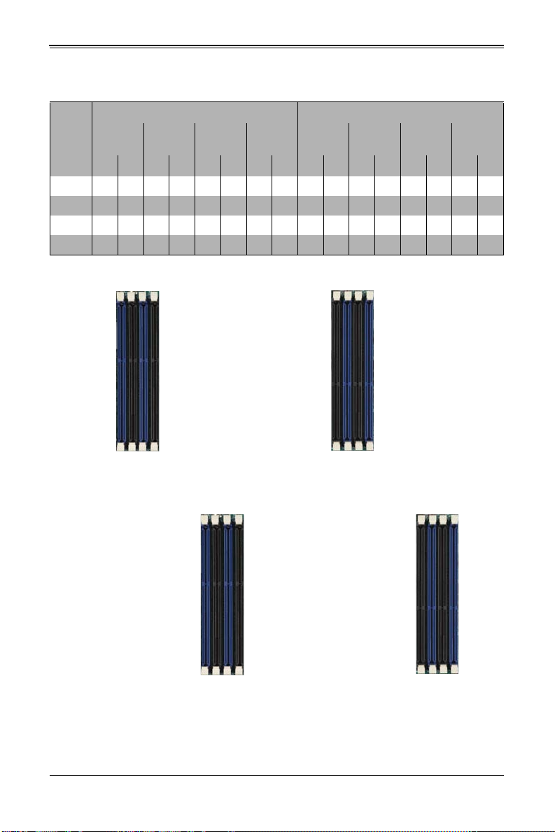
Table 3-1. Populating Eight Memory Slots for Interleaved Operation
CPU1 CPU2
# of
DIMMs
4XX XX
8 X X X X X X X X
12 XXXXX X XXXXX X
16 X X X X X X X X X X X X X X X X
Channel AChannel BChannel CChannel DChannel EChannel FChannel GChannel
H
A1 A2 B1 B2 C1 C2 D1 D2 E1 E2 F1 F2 G1 G2 H1 H2
Figure 3-13. 16-slot DIMM Numbering
Note: Though multiple DIMM memory module types and speeds may be supported, you
need to use DIMM memory modules of the same speed and type.
Note: An “X” in Table 3-1 indicates the memory slot is populated by a DIMM module.
3-10
Page 43

Chapter 3: Setup and Installation
To Install: Insert module vertically
and press down until it snaps into
place. Pay attention to the bottom
notch.
To Remove: Use your thumbs to
gently push each release tab
outward to free the DIMM from the
slot.
Note: The notch should align with
the receptive key point on the slot.
Side View
Top View
Notch
Release Tabs
Note: For an optimized memory bandwidth, it is recommended that you populate the
memory modules in sets of four (4) DIMMs for the CPU’s.
DIMM Installation
Caution: Exercise extreme care when installing or removing DIMM modules to prevent any
possible damage.
Installing DIMM Memory Modules
1. Power down the blade module (see "Powering Down a Blade Unit" on page 3-1).
2. Remove the blade from the enclosure and the cover from the blade (see
"Removing/Replacing the Blade Cover" on page 3-2).
3. Remove the air shroud that covers the DIMM slots.
4. Insert each DIMM vertically into its slot, starting with slots A1 and A2. Pay attention
to the notch along the bottom of the module to prevent inserting the DIMM
incorrectly (see Figure 3-14).
Figure 3-14. Installing a DIMM into a Memory Slot
5. Gently press down on the DIMM until it snaps into place in the slot. Repeat for all
modules (see Table 3-1 for installing DIMMs into the slots in the correct order).
6. Replace the air shroud and the blade cover and install the blade module back into
the enclosure.
7. Power up the blade unit (see "Powering Up a Blade Unit" on page 3-1).
3-11
Page 44

SBI-7127R-S6 Blade Module User’s Manual
3-6 Hard Disk Drive Installation
Hard disk drives are installed in “carriers” which are hot-swappable and can be removed
or replaced without powering down the blade unit they reside in. A blade module needs
a hard disk drive with an operating system installed to operate.
Caution: To maintain proper airflow, both hard drive bays must have drive carriers inserted
during operation whether or not a drive is installed in the carrier.
To remove a hard drive carrier, do the following:
Removing a Hard Drive Carrier
1. Locate the colored “Open” button at the bottom of the drive carrier and press it with
your thumb. This action releases the drive carrier from the drive bay.
2. Pull the release handle out about 45-degrees, then use it to pull the drive carrier out.
To Install a hard drive, use the following procedure:
Installing a Hard Drive
1. Remove a blank drive carrier from the blade (see removal procedure above).
2. Insert a drive into the carrier with the PCB side facing down and the connector end
toward the rear of the carrier.
3. Align the drive in the carrier so that the screw holes of both line up. Note that there
are holes in the carrier marked “SATA” to aid in correct installation.
4. Secure the drive to the carrier with six screws as shown in Figure 3-15.
5. Insert the drive carrier into its slot keeping the Open button at the bottom. When the
carrier reaches the rear of the bay the release handle will retract.
6. Push the handle in until you hear the carrier click into its locked position.
3-12
Page 45

Chapter 3: Setup and Installation
Figure 3-15. Installing a Hard Drive in a Carrier
3-7 Installing the Operating System
An operating system (OS) must be installed on each blade module. Blades with
Microsoft Windows OS and blades with Linux OS can both occupy and operate within
the same blade enclosure. Refer to the SuperMicro web site for a complete list of
supported operating systems.
There are several methods of installing an OS to the blade modules.
Installing with an External USB CD-ROM Drive
The most common method of installing the OS is with an external USB CD-ROM drive.
Take the following steps to install the OS to a blade module:
Caution: Installing the OS from an external CD-ROM drive may take several hours to
complete.
1. Connect an SUV cable (Serial port/USB port/Video port cable) to the KVM
connector on the front of the blade module. You will then need to attach a USB hub
to the USB port on this cable to provide multiple USB ports.
2. Connect the external CD-ROM drive, a USB keyboard and a mouse to the USB hub.
You will also need to connect a monitor to the video connector on the SUV cable.
Turn on the blade module.
3. Insert the CD containing the OS into the CD-ROM drive.
4. Follow the prompts to begin the installation.
3-13
Page 46

SBI-7127R-S6 Blade Module User’s Manual
Installing via PXE Boot
PXE (Preboot Execution Environment) is used to boot a computer over a network. To
install the OS via PXE, the following conditions must be met:
1. The PXE B
2. A PXE server has been configured (this can be another blade in the system).
3. The PXE server must be connected over a network to the blade to be booted.
4. The blade has only non-partitioned/unformatted hard drives installed and no
bootable devices attached to it.
Once these conditions are met, make sure the PXE server is running. Then turn on the
blade on which you wish to boot and/or install the OS. The BIOS in the blade will look at
all bootable devices and finding none will connect to the PXE server to begin the boot/
install.
OOT option in BIOS must be enabled.
Installing via Virtual Media (Drive Redirection)
You can install the OS via Virtual Media through either the IPMIview (Java based client
utility), IPMItool or the Web-based Management Utility. With this method, the OS is
installed from an ISO image that resides on another system/blade.
Refer to the manuals on your SuperBlade CD-ROM for further details on the Virtual
Media (CD-ROM or Drive Redirection) sections of these two utility programs.
3-14
Page 47

Chapter 3: Setup and Installation
3-8 Management Software
System management may be performed with either of three software packages:
IPMIview, IPMItool or a Web-based Management Utility. These are designed to provide
an administrator with a comprehensive set of functions and monitored data to keep tabs
on the system and perform management activities.
Refer to the manuals on your SuperBlade CD-ROM for further details on the various
functions provided by these management programs.
3-9 Configuring and Setting up RAID
Each blade module that supports two or more hard drives may be used to create a RAID
array. The procedures for doing this vary depending upon the blade model chosen for
your SuperBlade system.
See Chapter 1 for details on how to configure and set up RAID on your blade module.
3-15
Page 48

SBI-7127R-S6 Blade Module User’s Manual
Notes
3-16
Page 49

Chapter 4
Blade Module Features
Figure 4-1. SBI-7127R-S6 Blade Unit Front View
This chapter describes the SBI-7127R-S6 blade unit. Installation and maintenance
should be performed by experienced technicians only.
See Figure 4-1 for a front view of the blade unit and Table 4-1 for its features.
Table 4-1. SBI-7127R-S6 Blade Unit Features
Feature Description
Processors
Memory
Storage Up to six hot-plug 2.5" hot pluggable enterprise SATA/SAS/ SSD drives
Ports KVM port (1), SATA port (1)
Features
Supports single or dual 2011-pin Socket R (LGA 2011) E5-2600 series
processors
Supports up to 512 GB of RDIMM and 128 GB of UDIMM DDR3 1600/
1333/1066/800 MHz speed, 32GB, 16GB, 8GB, 4GB, 2GB and 1GB size
SDRAM memory in sixteen (16) 240-pin DIMM sockets
Onboard Integrated Matrox G200 Graphics chip, IPMI 2.0, ATA/100, Plug
and Play, APM 1. 2, DMI 2.3, PCI 2.2, ACPI 1.0/2.0, SMBIOS 2.3, Real
Time Clock, Watch Dog,
4-1
Page 50
SBI-7127R-S6 Blade Module User’s Manual
1
5
4
3
6
7
2
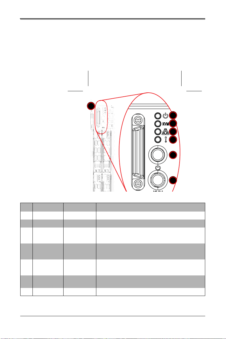
4-1 Control Panel
Each blade has a similar control panel (Figure 4-2) with power on/off button, a KVM
connector, a KVM button and four LEDs on the top front of the unit. The numbers
mentioned in Figure 4-2are described in Table 4-2.
Figure 4-2. Blade Control Panel
Table 4-2. Blade Control Panel
Item Function State Description
1 Power Button N/A Turns blade module on and off
2 KVM Button N/A Initiates KVM function
3 Power LED
4 KVM/UID LED
5 Network/IB LED
System Fault
6
LED
7 KVM Connector N/A Connector for SUV/KVM cable
Green Indicates power status “On”
Orange Indicates power status “Off” (with power cables plugged in)
Blue Indicates KVM being utilized on blade unit
Flashing Blue Indicates UID activated on blade module
Flashing Green Indicates network activity over LAN
Flashing Orange Indicates network activity over InfiniBand module
Red
Indicates a memory error, overheat, VGA error or any error
that prevents booting
4-2
Page 51

Chapter 4: Blade Module Features
Power Button
Each blade has its own power button so that individual blade units within the enclosure
may be turned on or off independently of the others. Press the power button (#1) to turn
on the blade server. The power LED (#3) will turn green. To turn off, press and hold the
power button for >4 seconds and the power LED will turn orange.
KVM Button
KVM stands for Keyboard/Video/Mouse. With KVM, a user can control multiple blades
with a single keyboard/video/mouse setup. Connect your keyboard, mouse and monitor
to the USB and VGA connectors on the CMM module, then push the KVM button on the
control panel of the blade module you wish to access.
LED Indicators
Blade module LEDs are described below in Table 4-3.
Table 4-3. Blade Module LED Indicators
LED State Description
Green Po w er On
Power LED
KVM/UID LED
(Blue)
Network LED
(Green)
System Fault
LED (Red)
Amber Standby
Red Power Failure
Steady On Indicates that KVM has been initialized on this blade module
Flashing
Flashing
Steady On
Serves as a UID indicator (the UID function is activated with a
management program)
Flashes on and off to indicate traffic (Tx and Rx data) on the LAN
connection to this blade module.
This LED illuminates red when a fatal error occurs. This may be the
result of a memory error, a VGA error or any other f atal error that
prevents the operating system from booting up.
a
a. In the event of a power failure, the N+1 Redundant Power Supply (if included in your
system's configuration) automatically turns on and picks up the system load to provide
uninterrupted operation. The failed power supply should be replaced with a new one as
soon as possible.
KVM Connector
Alternatively, you may connect a KVM cable (CBL-0218L, with a keyboard/video/mouse
attached) to the KVM connector (#7) of the blade you wish to access. To switch to
another blade, disconnect the cable then reconnect it to the new blade.
See the Web-based Management Utility User’s Manual on your SuperBlade system
CD-ROM for further details on using the KVM function remotely.
4-3
Page 52

SBI-7127R-S6 Blade Module User’s Manual
1
2
4
3
7
6
9
8
10
3 3
3
6
5
4-2 Mainboard
The mainboard of the SBI-7127R-S6 blade unit is a proprietary design, which is based
on the Intel C602J chipset. See Figure 4-4 for a block diagram of this chipset, Figure 4-3
for a view of the B9DR7 mainboard and Figure 4-5 for an exploded view diagram of the
blade unit.
Figure 4-3. B9DR7 Mainboard
4-4
Page 53

Chapter 4: Blade Module Features
QPI
#1
DDR3 DIMM
#2
DDR3 DIMM
DDR3 DIMM
DDR3 DIMM
DDR3 DIMM
#2
#1
DDR3 DIMM
C602
PATSBURG
Chipset
AT25321
LPC
CPU Rear
Socket 1
Processor
SandyBridge
USB
Front
CMM (TOP)
0,1
CMM (BOT)
TPM HDR
Internal
2
QPI
DDR3 DIMM
DDR3 DIMM
#1
#2
#1
#2
#1
#2
#1
#2
#1
#2
#1
#2
DMI
x8
x4
VGA Front
CMM (TOP)
CMM (BOT)
SH7757
VGA BMC
DDR III
PHY1 & 2
RTL8201
CMM TOP & BOT
SPI
SAS #2
SAS #1
SAS #3
SAS #4
SAS #5
SAS #6
SAS
x1
45
x4
LAN
Powerville
IB
x8
SAS2208
CPU Front
Socket 0
Processor
SandyBridge
Table 4-4. B9DR7 Mainboard Layout
Item Description
1LGA 2011 CPU1 Socket
2 LGA 2011 CPU2 Socket
3 DIMM Slots (see Figure 3-13: "16-slot DIMM Numbering" on page 3-10 for details)
4 six 2.5" SATA Hard Drive Bays
5 InfiniBand daughter card (connectors under card not shown)
6 Gbx Connectors (for power and logic to backplane)
7 Onboard SATA Port
8 Intel C602J Chipset
9 Onboard Battery
10 KVM Module
Figure 4-4. Intel C602J/Intel 602J Chipset: Block Diagram
4-5
Page 54

SBI-7127R-S6 Blade Module User’s Manual
Jumpers
The jumpers present on the mainboard are used by the manufacturer only; there are no
jumpers used to configure the operation of the mainboard.
CMOS Clear
JBT1 is used to clear CMOS and will also clear any passwords. JBT1 consists of two
contact pads located near the BIOS chip.
Clearing CMOS
1. First power down the blade and remove it from the enclosure.
2. Remove the blade cover to access the mainboard (see "Removing/Replacing the
Blade Cover" on page 3-2 for further details). Short the CMOS pads with a metal
object such as a small screwdriver.
3. Replace the cover, install the blade back into the enclosure and power it on.
4-6
Page 55
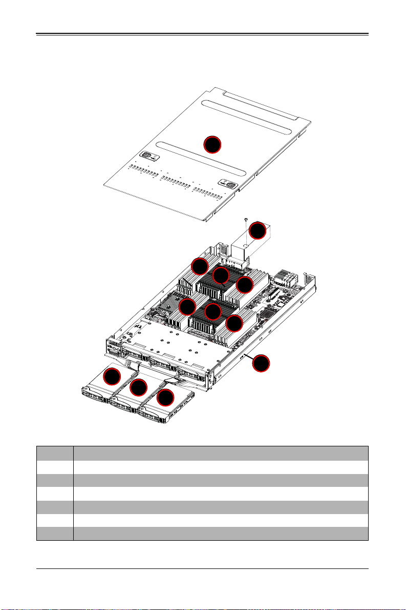
4-3 Blade Unit Components
2
2
3
5
6
2
1
4
3
3
3
4
Figure 4-5. Exploded View of a SBI-7127R-S6 Blade Module
Chapter 4: Blade Module Features
Table 4-5. Main Components of a SBI-7127R-S6 Blade Module
Item Description
1 Blade Unit/Module
2 2.5" Hard Drives
3 DIMMs (system memory)
4 CPU/Heatsinks (2)
5 Top Cover
6 Air Shroud
4-7
Page 56

SBI-7127R-S6 Blade Module User’s Manual
Memory Support
The SBI-7127R-S6 blade module supports up to 512 GB of RDIMM and 128 GB of
UDIMM DDR3 1600/1333/1066/800 MHz speed, 32GB, 16GB, 8GB, 4GB, 2GB and
1GB size SDRAM memory in sixteen (16) 240-pin DIMM sockets. See Section 3-5:
Memory Installation on page 3-9 for further details on mainboard memory installation.
Hard Disk Drives
The SBI-7127R-S6 blade unit accommodates up to six 2.5" SATA/SAS/SSD hard disk
drives, which are mounted in drive “trays”. The drives can be hot-swapped and removed
or replaced without powering down the blade unit they reside in. The six drives can be
used to set up a RAID array (RAID 0, 1, 5 and 10 Windows; RAID 0, 1 and 10 Linux;
RAID 0, 1, 5, 6, 10 and 50 SAS) or JBOD. These drives use a yellow color for the Blade
HDD active LED. See Chapter 1 for further details on RAID Setup.
Caution: To maintain proper airflow, both hard drive bays must have drive carriers inserted
during operation whether or not a drive is installed in the tray.
4-8
Page 57

Chapter 5
BIOS
5-1 Introduction
This chapter describes the BIOS for Intel SuperBlade modules. The Intel Blade modules
use a 16 Mb SPI Flash EEPROM with AMI® BIOS™ that is stored in a flash chip. This
BIOS can be easily upgraded using a floppy disk-based program.
Note: Due to periodic changes to the BIOS, some settings may have been added or
deleted and might not yet be recorded in this manual. Please refer to the http://
www.supermicro.com/products/SuperBlade/module/ web site for further details on BIOS
setup and the BIOS menus for your SuperBlade blade module.
System BIOS
BIOS stands for Basic Input Output System. The 16 Mb SPI Flash EEPROM with AMI®
BIOS BIOS flash chip stores the system parameters, types of disk drives, video
displays, in the CMOS. The CMOS memory requires very little electrical power. When
the blade unit is turned off, a backup battery provides power to the BIOS flash chip,
enabling it to retain system parameters. Each time the blade is powered on it is
configured with the values stored in the BIOS ROM by the system BIOS, which gains
control at boot up.
How To Change the Configuration Data
The CMOS information that determines the system parameters may be changed by
entering the BIOS Setup utility. This Setup utility can be accessed by pressing the
<D
ELETE> key at the appropriate time during system boot. (See "Starting the Setup
Utility" below.)
Starting the Setup Utility
Normally, the only visible POST (Power-On Self-Test) routine is the memory test. As the
memory is being tested, press the <D
Setup utility. From the main menu, you can access the other setup screens, such as the
Security and Power menus.
Caution: To prevent possible boot failure, do not shut down or reset the system while
updating the BIOS.
ELETE> key to enter the main menu of the BIOS
5-1
Page 58

SBI-7127R-S6 Blade Module User’s Manual
5-2 BIOS Updates
It may be necessary to update the BIOS used in the blade modules on occasion.
However, it is recommended that you not update BIOS if you are not experiencing
problems with a blade module.
Updated BIOS files are located on our web site(www.supermicro.com/products/
superblade/). Please check the current BIOS revision and make sure it is newer than
your current BIOS before downloading.
There are several methods you may use to upgrade (flash) your BIOS. After
downloading the appropriate BIOS file (in a zip file format), follow one of the methods
described below to flash the new BIOS.
Flashing BIOS
Use the procedures below to “Flash” your BIOS with a new update using the KVM
dongle, USB ports on the CMM module or by use of a Floppy disk.
Flashing a BIOS using the KVM Dongle:
For this method, you must use a KVM “dongle” cable (CBL-0218L, included with the
system).
1. Copy the contents of the zip file to a bootable USB pen drive.
2. Connect the KVM dongle (CBL-0218L) to the KVM connector at the front of the
blade you will be flashing the BIOS to.
3. Connect your bootable USB pen drive to one of the two USB slots on the KVM
dongle.
4. Boot to the USB pen drive and go to the directory where you saved the contents of
the zip file.
5. Type flash filename.rom (replace filename.rom by the actual ROM file name).
Flashing a BIOS using the USB Ports on the CMM:
1. Copy the contents of the zip file to a bootable USB pen drive.
2. Connect your bootable USB pen drive to one of the two USB slots on the CMM
(located on the back side of the enclosure).
3. Boot to the USB pen drive and go to the directory where you saved the contents of
the zip file.
4. Type flash filename.rom (replace filename.rom by the actual ROM file name).
Flashing a BIOS using a Floppy Image File
This method must be performed remotely.
1. Copy the image file from the zip file to your desktop.
2. Use the web browser or IPMIView to access your CMM remotely using its IP
Address.
5-2
Page 59

Chapter 5: BIOS
3. Go to the VIRTUAL MEDIA menu and select FLOPPY IMAGE UPLOAD.
4. BROWSE or OPEN to locate the *.img file on your desktop and select it.
5. Press the UPLOAD button and wait a few seconds for the image to upload to the
CMM.
6. Once the upload finishes, turn on the blade module and press <D
EL> to enter the
BIOS setup utility.
7. In the B
OOT MENU, bring USB LS120: PEPPCMM VIRTUAL DISC 1 to the top of
the boot priority list.
8. Exit while saving the changes. The blade module will boot to the virtual media
(floppy image) A:\>.
9. Type flash filename.rom.
Note: Replace filename.rom by the actual ROM file name (such as B8DTE142.rom for
example) in the command.
5-3 Running Setup
Note: Default settings are in bold text unless otherwise noted.
The BIOS setup options described in this section are selected by choosing the
appropriate text from the M
section, although the screen display is often all you need to understand how to set the
options.
When you first power on the computer, the BIOS is immediately activated.
While the BIOS is in control, the Setup program can be activated in one of two ways:
1. By pressing <D
2. When the message Press the <Delete> key to enter Setup appears briefly at the
bottom of the screen during the POST, press the <D
S
ETUP menu:
AIN BIOS SETUP screen. All displayed text is described in this
ELETE> immediately after turning the system on, or
ELETE> key to activate the main
5-3
Page 60
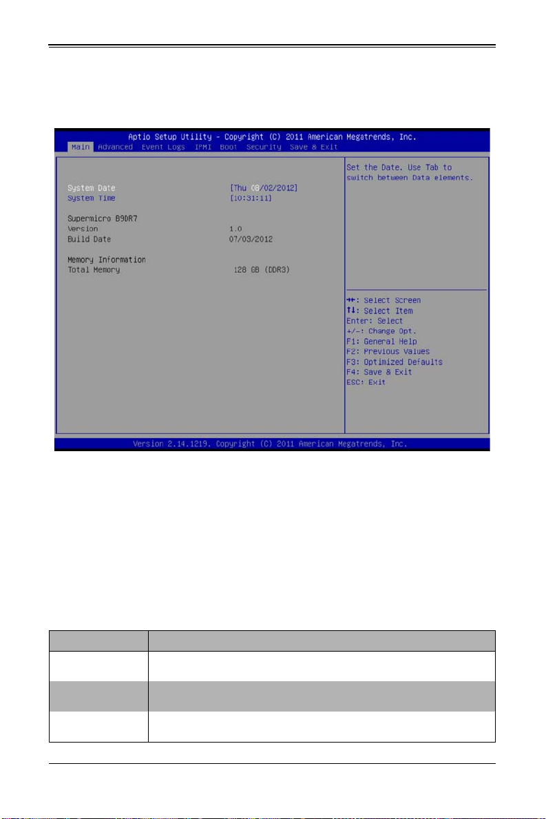
SBI-7127R-S6 Blade Module User’s Manual
5-4 Main BIOS Setup
Figure 5-1. BIOS Setup Screen
All Main Setup options are described in this section.
Use the UP/DOWN arrow keys to move among the different settings in each menu. Use
the L
EFT/RIGHT arrow keys to change the options for each setting.
Press the <E
SC> key to exit the CMOS SETUP menu. The next section describes in
detail how to navigate through the menus.
Items that use sub-menus are indicated with the
press the <E
Menu options found in the M
NTER> key to access the submenu.
AIN BIOS SETUP menu are described in Table 5-1.
icon. With the item highlighted,
Table 5-1. Main BIOS Setup Menu Options
Menu Option Description
System Date
System Time
BIOS Information
Using the arrow keys, highlight the month, day and year fields, and enter the
correct data for the system date. Press the <Enter> key to save the data.
T o set the syst em date an d time, key in the correct i nformat ion in the ap propriate
fields. Then press the <Enter> key to save the data.
BIOS static display information including the mot herboard number, SMC version,
SMC Build Date and Total Memory is also shown on the screen.
5-4
Page 61
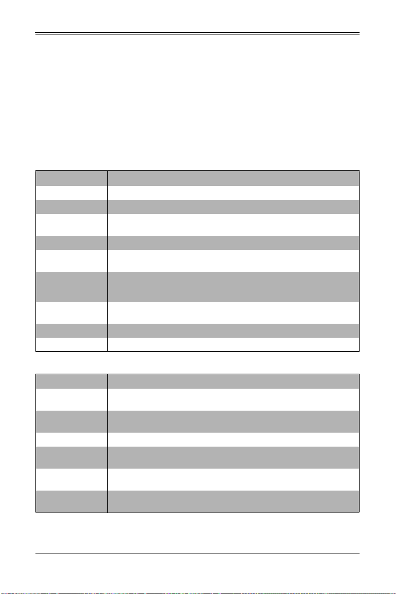
Chapter 5: BIOS
5-5 Advanced Setup
Choose Advanced from the BIOS Setup Utility main menu with the arrow keys to
display the A
sub-menus that can be accessed by highlighting the item and pressing <E
Options for PIR settings are displayed by highlighting the setting option using the arrow
keys and pressing <E
Table 5-2 describes all sub-menus found in the ADVANCED SETUP menu.
Sub-menu Description
Boot Feature See Table 5-3 for a description of BIOS setup menu options in this sub-menu.
CPU Configuration See Table 5-4 for a description of BIOS setup menu options in this sub-menu.
Chipset
Configuration
SATA Configuration See Table 5-6 for a description of BIOS setup menu opti ons in this sub-menu.
PCIe/PII/PnP
Configuration
Super IO
Configuration
(SH7757)
Serial Port Console
Redirection
ACPI Settings See Table 5-10 for a description of BIOS setup menu options in this sub-menu.
ME Subsystem See Table 5-11 for a description of BIOS setup menu options in this sub-menu.
DVANCED SETUP menu. The items with a triangle beside them are
NTER>.
NTER>.
Table 5-2. Advanced Setup Menu Options
See Table 5-5 for a description of BIOS setup menu options in this sub-menu.
See Table 5-7 for a description of BIOS setup menu options in this sub-menu.
See Table 5-8 for a description of BIOS setup menu options in this sub-menu.
See Table 5-9 for a description of BIOS setup menu options in this sub-menu.
Table 5-3. Boot Feature Submenu
Menu Option Description
Quiet Boot
AddOn ROM Display
Mode
Bootup NUM-Lock This setting selects the Power-On state for Numlock. Options include On or Off.
Wait for ‘F1’ If Error
Interrupt 19 Capture
Watch Dog Timer
When Disabled the BIOS displays normal POST messages. When Enabled the
BIOS displays an OEM Logo instead of POST messages.
This setting sets the display mode for Option ROM. Option s include Force BIOS
or Keep Current.
When enabled, the system will wait for the F1 key to be pressed if an error
occurs. Options are Enabled or Disabled.
When enabled this setting allows option ROMs to trap Interrup 19. Options
include Enabled or Disabled.
This setting allows the system to restart when it is not active more than 5
minutes. Option include Enabled and Disabled.
5-5
Page 62

SBI-7127R-S6 Blade Module User’s Manual
Table 5-3. Boot Feature Submenu (Continued)
Menu Option Description
Power Button
Function
Restore on AC Power
Loss
Menu Option Description
Socket 1 CPU
Information
Socket 2 CPU
Information
Clock Spread
Spectrum
Hyper-threading
Active Processor
Cores
Limit CPUID
Maximum
Execute Disable Bit
Hardware Prefetcher
Adjacent Cache Line
Prefetch
DCU Streamer
Prefetcher
DCU IP Prefetcher
This setting specifies the power button’s function when p ressed. Option include 4
Seconds Override or Instant Off.
This setting specifies what the system will do when power is restored after an AC
power loss to the system. Options include Stay Off (system power remains off
after power loss), Power-On (system power turns on after power loss) or Last
State (allows the system to resume its last state before the power loss).
Table 5-4. CPU Configuration Submenu
These submenus, when selected, shows information on the Socket 1/Socket 2
processors and other information including CPU Signature, Microcode Patch,
CPU Stepping, Max CPU Speed, Min CPU Speed, Processor Cores, Intel HT
Technology, Intel VT-x Techn
ology, L1 Data Cache, L1 Code Cache, L2 Cache and L3 Cache.
Additionally, the CPU Configuration submenu shows information about the CPU
Speed and 64-bit support.
This information is only readable and cannot be changed.
This setting enables or disables spread spectrum modulation. Options are
Enabled and Disabled.
This setting is Enabled for Windows XP and Linux (OS optimized for
Hyper-threading technology), and Disabled for other OSes (any OS not
optimized for Hyper-threading techology). When Disabled, only one thread per
enabled core is enabled.
This setting selects the number of cores to enable in each processor package.
Options include All, 1, 2, 4 and 6.
This setting is disabled for Windows XP. Options include Enabled or Disabled.
XD can prevent certain classes of malicious buffer overflow attacks when
combined with a supporting OS such as Windows Server 2003 SP1, Windows
XP SP2, SuSE Linux 9.2 or RedHat Enterprise 3 Update 3. Options include
Enabled or Disabled.
If set to Enabled, the hardware prefetcher will prefetch streams of data and
instructions from the main memory to the L2 cache in the forward or backward
manner to improve CPU performance. Options are Enabled and Disabled.
For UP platforms leave it enabled. for DP/MP servers, this setting may be used
to tune performance to the specific application.
The CPU fetches the cache line for 64-bytes if this option is set to Disabled. The
CPU fetches both cache lines for 128-bytes as comprised if Enabled.
For UP platforms leave it enabled. for DP/MP servers, this setting may be used
to tune performance to the specific application.
For UP platforms, leave this option Enabled. For DP/MP servers, this option
may be used to tune performance to the specific application. Options are
Enabled or Disabled.
This setting Enables or Disables prefetch of the next L1 line based upon
sequential load history.
5-6
Page 63

Table 5-4. CPU Configuration Submenu (Continued)
Menu Option Description
Select Enabled to use this Virtualization Technology feature to allow one
platform to run multiple operating systems and applications in independent
Intel® Virtualization
Technology
CPU Power
Management
Configuration
Power Technology
Energy
Performance
Long Duration
Power Limit
Long Duration
Maintained
Short Duration
Power Limit
partitions, creating multiple “virtual” systems in one physical computer syst em.
The options are Enabled and Disabled. Please refer to the Intel website for
further detailed information.
NOTE: A full reset of the system is required when you change this setting.
Power manage
ment options and information is displayed on this submenu. In addition to th e
options in this submenu, information is displayed for Factory Long Duration
Power Limit, Factory Long Duration Maintained and Recommended Short
Duration Power.
This option enables power managment features. Options include Disable,
Energy Efficient and Custom. Selecting “Custom” allows you to either Enable or
Disable the following features and their defaults:
• EIST (Enabled)
• Turbot Mode (Enabled)
• C1E Support (Enabled)
• CPU C3 Report (Disabled)
• CPU C6 Report (Enabled)
• CPU C7 Report (Enabled)
• Package C-state Limit (C6)
• Energy Performance
• Long Duration Power Limit
• Long Duration Maintained
• Short Duration Power Limit
This option allows you to optimize between power and energy savings. Windows
2008 and later OSes overides this value according to its power plan. Options
include Performance, Balanced Performance, Balanced Energy and Energy
Efficient.
This option allows you to set the long duration power limit in Watts. To set the
value, enter a number from your keyboard in the field highlighted. To reset the
number, enter a new number.
This option allows you to set the time window for which the long duration power
limit is maintained. To set the time value, enter a number from your keyboard in
the field highlighted. To reset the number, enter a new number.
This option allows you to set the short duration power limit in Watt s. To set the
value, enter a number from your keyboard in the field highlighted. To reset the
number, enter a new number.
Chapter 5: BIOS
5-7
Page 64

SBI-7127R-S6 Blade Module User’s Manual
Table 5-5. Chipset Configuration Sub-menu
Menu Option Description
North Bridge
Configuration
IOH
Configuration
Intel VT-d
Intel I/OAT
DCA Support This setting allows you to Enable or Disable DCA support in your system.
IOH 0/1
PCIe Port
Bifurcation
Controls
QPI
Configuration
Isoc This setting allows you to Enable or Disable Isoc in your system.
QPI Link
Speed Mode
QPI Link
Frequency
Select
DIMM
Configuration
DIMM
Information
Memory Mode
DRAM RAPL
Mode
DDR Speed
Channel
Interleaving
This sub-menu configures North Bridge features and shows configuration
information.
This submenu configures Intel VT-d and Intel I/OAT in your system and
configures IOU PCIe port bifurcation controls.
This setting allows you to Enable or Disable Intel Virtualization Technology for in
your system.
This setting allows you to Enable or Disable Intel I/O Acceleration T echnology in
your system.
Both IOH 0 and IOH 1 PCIe port bifurcation controls are available to set IOU Link
Speed and PCIe Port sett ings. Options include Gen 1, Gen 2 or Gen 3 link speed
settings or various port PCIe settings for x4x4, x8, x4x4x4, x4x4x8, x8x4x4, x8x8
or x16 (default depends upon setting).
This submenu statically displays Current QPI Link Speed and Current QPI Link
Freq as well as providing options for Isoc, QPI Link Speed Mod e and QPI Link
Frequency Select.
This setting allows you to select QPI Link Speed as being either Fast or Slow
mode.
This setting allows you to select the QPI link frequency. Options include Auto,
6.4 GT/s, 7.2 GT/s or 8.0 GT/s.
This submenu displays static Memory Configuration information (Current
Memory Mode, Current Memory Speed, Mirroring and Sparing), DIMM
Information and other option settings.
DIMM presence and size information is shown in this submenu when selected.
This setting sets the system memory mode. Options include the following:
• Independent (default) – All DIMMs are available to the operating system.
• Mirroring – The mainboard maintains two identical copies of all data in
memory for redundancy .
• Lock Step – The mainboard uses two areas of memory to run the same set
of operations in parallel.
• Sparing – A preset threshold of correctable errors is used t o trigger fail- over.
The spare memory is put online and used as active memory in place of the
failed memory.
This setting allows you to select DRAM RAPL Mode for your system. Options
include Disabled, DRAM RAPL Mode0 and DRAM RAPL MODE1.
This setting allows you to force DDR speed for your system. Options include
Auto, Force DDR3 800, Force DDR 1066, Force DDR 1333, Force DDR 1600
and Force SPD.
This setting allows you to select different channel interleaving sett i ngs. Options
include Auto, 1 Way, 2 Way, 3 Way and 4 Way.
5-8
Page 65

Chapter 5: BIOS
Table 5-5. Chipset Configuration Sub-menu (Continued)
Menu Option Description
Rank
Interleaving
Patrol Scrub This setting allows you to either Enable or Disable Patrol Scrub for your system.
Demand
Scrub
Data
Scrambling
Device
Tagging
Thermal
Throttling
South Bridge
Configuration
All USB Devices
EHCI Controller 1/
EHCI Controller 2
Legacy USB
Support
Port 60/64
Emulation
EHCI Hand-off
This setting allows you to select different rank interleaving settings. Options
include Auto, 1 Way, 2 Way, 4 Way and 8 Way.
This setting allows you to Enable or Disable the Demand Scrubbing in your
system.
This setting allows you to Enable or Disable the Data Scrambling in your system.
This setting allows you to Enable or Disable the Device Tagging in your system.
For this setting, selecting Disabled sets Open Loop Thermal Throttling, whereas
selecting CLTT sets Closed Loop Thermal Throttling.
This sub-menu static displays PCH Information (chipset Name, Stepping and
USB Devices), and allows you to configure other South Bridge features.
This setting allows you to enable USB devices in your system. Options include
Enabled or Disabled.
This setting allows you to Enable or Disabled USB 2.0 (EHCI) support for
Controller 1/2.
This setting allows you to enable the use of Legacy USB devices. If t his option is
set to Auto, legacy USB support will be automatically enabled if a legacy USB
device is installed on the mainboard, and disabled if no USB devices are
connected. The options include Disabled, Enabled and Auto.
This setting Enables or Disables I/O port 60h/64h emulation support. This
should be enabled for the complete USB keyboard legacy support for non-USB
aware OSes.
This setting is a workaround for OSes without EHCI hand-off support. The EHCI
ownership change should be claimed by the EHCI driver. Options include
Enabled or Disabled.
Table 5-6. SATA Configuration Sub-menu
Menu Option Description
SATA Mode
Aggressive Link
Power Management
Port 0 Hog Plug
Staggered Startup (5)
This setting allows you to specify the SATA mode used for your system. Options
include Disabled, IDE Mode, AHCI Mode and RAID Mode.
This setting allows you to Enable or Disable Aggressive Link Power
Management for your system.
These settings allow you to Enable or Disable SATA Port Hot Plug support for
each port specified.
These settings allow you to Enable or Disable AHCI Staggered Spin-up support
for each drive.
5-9
Page 66

SBI-7127R-S6 Blade Module User’s Manual
Table 5-7. PCIe/PCI/PnP Configuration Sub-menu
Menu Option Description
PCI ROM Priority
PCI Latency Timer
Above 4G Decoding
PERR# Generation
SERR# Generation
Maximum Payload
Maximum Read
Request
ASPM Support
Onboard LAN Option
ROM Select
Load Onboard LAN 1
Option ROM
Load Onboard LAN 2
Option ROM
Network Stack This setting allows you to Enable or Disable th e network stack (Pxe and UEFI).
Use this setting in case of multiple Option ROMs to specify what PCI Option
ROM to launch. Options include Legacy ROM and EFI Compatible ROM.
This sets the value to programmed into the PCI Laten cy Timer Register. O ptions
include 32, 64, 96, 128, 160, 192, 224 an 248.PCI Bus Clocks.
This setting allows you to Enable or Disable decoding of 64-bit capable devices
in the Above 4G Address Space. This setting is only usable if your system
supports 64-bit PCI decoding.
This setting allows you to Enable or Disable the PCI device to generate a
PERR#.
This setting allows you to Enable or Disable the PCI device to generate a
SERR#.
Use this setting to set the maximum payload of the PCI Express device or allow
the system BIOS to select the value. Options include Auto, 128 Bytes, 256
Bytes, 512 Bytes, 1024 Bytes, 2048 Bytes or 4096 Bytes.
Use this setting to set the maximum read reque st size of the PCI Express device
or allow the system BIOS to select the value. Options include Auto, 128 Bytes,
256 Bytes, 512 Bytes, 1024 Bytes, 2048 Bytes or 4096 Bytes.
This sets the ASPM Level for your system. Options include Disabled (disables
ASPM), Auto (lets BIOS auto configure) or Force L0s (force all links to L0s sta te).
This setting allows you to select the onboard LAN option ROM to be either PXE
or iSCSI. Note: If iSCSI is selected, LAN1 Option ROM select will cover all other
Oboard LANs.
This setting Enables or Disables onboard option ROM for LAN1.
This setting Enables or Disables onboard option ROM for LAN2.
Table 5-8. SuperIO Device Configuration Sub-menu
Menu Option Description
Super IO Chip
Serial Port 1
Configuration
Serial Port This setting allows you to Enable or Disable the Serial Port.
Device Settings This static display shows device settings for serial port 1 configuration.
Change Settings
Serial Port Mode
This static display shows the name of the Super IO chip installed for your
system.
This submenu allows you to configure Serial Port 1.
Use this setting to select an opti mal sett ing fo r the Super IO devi ce t o use for the
Serial Port. Options include Auto, IO=3F8h/IRQ=4, IO=3F8h/IRQ=3~12,
IO=2F8h/IRQ=3~12, IO=3E8h/IRQ=3~12 and IO=2E8h/IRQ=3~12
This setting allows you to set the Serial Port Mode to either Normal or High
Speed.
5-10
Page 67

Chapter 5: BIOS
Table 5-8. SuperIO Device Configuration Sub-menu (Continued)
Menu Option Description
Serial Port 2
Configuration
submenu
Serial Port This setting allows you to Enable or Disable the Serial Port.
Device Settings This static display shows device settings for serial port 2 configuration.
Change Settings
Serial Port Mode
Menu Option Description
COM1
Console Redirection Use this setting to Enable or Disable Console Redirection for the COM1 port.
Console
Redirection Settings
Terminal Type
Bits per Second
Data Bits This sets the number of data bits as either 7 or 8.
Parity
Stop Bits
Flow Control
VT-UTF8 Combo
Key Support
Recorder Mode
This submenu allows you to configure Serial Port 2.
Use this setting to select an optimal setting for the Super IO device to use for the
Serial Port. Options include Auto, IO=3F8h/IRQ=4, IO=3F8h/IRQ=3~12,
IO=2F8h/IRQ=3~12, IO=3E8h/IRQ=3~12 and IO=2E8h/IRQ=3~12
This setting allows you to set the Serial Port Mode to either Normal or High
Speed.
Table 5-9. Serial Port Console Redirection Sub-menu
This submenu contains Console Redirection settings for the COM1 port. This
menu is only available when Console Redirection is enabled.
This setting allows you to select the Terminal Type to use for Console
Redirection emulation. Options include ANSI (extended ASCII character set),
VT100 (ASCII character set), VT100+ (extends VT100 to support color, function
keys, etc.) and VT-UTF8 (uses UTF8 encoding to map Unicode characters onto
one or more bytes).
This setting selects the serial port transmission speed, which must be matched
on the other side. Long or noisy lines may require lower speeds. O ptions inclu de
9600, 19200, 38400, 57600 and 115200.
A parity bit can be sent with the data bits to detect some transmission errors.
Options include None (no parity bit), Even (parity bit is 0 if the number of 1’s in
the data bits is even), Odd (parity bit is 0 if the number of 1’s in the data bits is
odd), Mark (parity bit is always 1) or Space (parity bit is always 0. The Mark and
Space Parity do not allow for error detection.
Stop bits indicate the end of a serial data packet (a start bit indicates the
beginning). The standard setting is 1 stop bit. Communications with slow de vices
may require more than 1 stop bit. Options are 1 or 2.
Flow control can prevent data loss from buffer overflow. When sending data, if
the receiving buffers are full, a ‘stop’ signal can be sent to stop the data flow.
Once the buffers are empty, a ‘start’ signal can be sent to re-start the flow.
Hardware flow control uses two wires to send start/stop signal s. Options include
None and Hardware RTS/CTS.
This setting Enables or Disables VT-UTF8 Combination Key support for ANSI/
VT100 terminals.
This setting Enables or Disables Recorder Mode. When enabled only text will be
sent. This is to capture Terminal data.
5-11
Page 68

SBI-7127R-S6 Blade Module User’s Manual
Table 5-9. Serial Port Console Redirection Sub-menu (Continued)
Menu Option Description
Resolution
100x31
Legacy OS
Redirection
Resolution
Putty KeyPad
COM2
Console Redirection Use this setting to Enable or Disable Console Redirection for the COM2 port.
Console
Redirection Settings
Terminal Type
Bits per Second
Data Bits This sets the number of data bits as either 7 or 8.
Parity
Stop Bits
Flow Control
VT-UTF8 Combo
Key Support
Recorder Mode
Resolution
100x31
Legacy OS
Redirection
Resolution
Putty KeyPad
This setting Enables or Disables extended terminal resolution.
This allows you to set for legacy OSes the number of rows and columns
supported for redirection. Options include 80x24 or 80x25.
This setting allows you to select the funtion key and KeyPad to use on the Putty
keyboard. Options include VT100, LINUX, XTERMR6, SCO, ESCN or VT400.
This submenu contains Console Redirection settings for the COM2 port.
This setting allows you to select the Terminal Type to use for Console
Redirection emulation. Options include ANSI (extended ASCII character set),
VT100 (ASCII character set), VT100+ (extends VT100 to support color, function
keys, etc.) and VT-UTF8 (uses UTF8 encoding to map Unicode characters onto
one or more bytes).
This setting selects the serial port transmission speed, which must be matched
on the other side. Long or noisy lines may require lower speeds. O ptions in clude
9600, 19200, 38400, 57600 and 115200.
A parity bit can be sent with the data bits to detect some transmission errors.
Options include None (no parity bit), Even (parity bit is 0 if the number of 1’s in
the data bits is even), Odd (parity bit is 0 if the number of 1’s in the data bits is
odd), Mark (parity bit is always 1) or Space (p arity bit is always 0. The Mark and
Space Parity do not allow for error detection.
Stop bits indicate the end of a serial data packet (a start bit indicates the
beginning). The standard setting is 1 stop bit. Communications with slow de vices
may require more than 1 stop bit. Options are 1 or 2.
Flow control can prevent data loss from buffer overflow. When sending data, if
the receiving buffers are full, a ‘stop’ signal can be sent to stop the data flow.
Once the buffers are empty, a ‘start’ signal can be sent to re-start the flow.
Hardware flow control uses two wires to send start/stop signal s. Options include
None and Hardware RTS/CTS.
This setting Enables or Disables VT-UTF8 Combination Key support for ANSI/
VT100 terminals.
This setting Enables or Disables Recorder Mode. When enabled only text will be
sent. This is to capture Terminal data.
This setting Enables or Disables extended terminal resolution.
This allows you to set for legacy OSes the number of rows and columns
supported for redirection. Options include 80x24 or 80x25.
This setting allows you to select the funtion key and KeyPad to use on the Putty
keyboard. Options include VT100, LINUX, XTERMR6, SCO, ESCN or VT400.
5-12
Page 69

Chapter 5: BIOS
Table 5-9. Serial Port Console Redirection Sub-menu (Continued)
Menu Option Description
Serial Port for Out-of-Band Management/Windows Emergency Management
Services (EMS)
Console Redirection
Console
Redirection Settings
Out-of-Band Mgmt
Port
Terminal Type
Bits per Second
Flow Control
Use this setting to Enable or Disable Console Redirection for Out-of-Band
Management/Windows Emergency Management Services (EMS).
This submenu contains Console Redirection settings for Out-of-Band
Management/Windows Emergency Management Services (EMS). Static display
information for Data Bits, Parity and Stop Bits is also shown in this submenu. It is
only enabled if the above Console Redirection setting is enabled.
Microsoft Windows Emergency Managment Services (EMS) allows for remote
managment of a Windows Server OS through a serial port. This setting allows
you to specify which port to use (COM1 or COM2).
VT-UTF8 is the preferred terminal type for out-of-band management. The next
best choice is VT100+ and then VT100. Options include ANSI (extended ASCII
character set), VT100 (ASCII character set), VT100+ (extends VT10 0 t o sup port
color, function keys, etc.) and VT-UTF8 (uses UTF8 encoding to map Unicode
characters onto one or more bytes).
This setting selects the serial port transmission speed, which must be matched
on the other side. Long or noisy lines may require lower speeds. O ptions inclu de
9600, 19200, 57600 and 115200.
Flow control can prevent data loss from buffer overflow. When sending data, if
the receiving buffers are full, a ‘stop’ signal can be sent to stop the data flow.
Once the buffers are empty, a ‘start’ signal can be sent to re-start the flow.
Hardware flow control uses two wires to send start/stop signal s. Options include
None, Hardware RTS/CTS and Software Xon/Xoff.
Table 5-10. ACPI Settings Sub-menu
Menu Option Description
ACPI Sleep State
Numa This setting Enables or Disables Non Uniform Memory Access (NUMA).
High Precision Timer Use this setting to Enable or Disable the High Precision Event Timer.
This setting selects the highest ACPI sleep state the system will enter when the
SUSPEND button is pressed. Options include Suspend Disabled and S1 (CPU
Stop Clock).
Table 5-11. ME Subsystem Sub-menu
Menu Option Description
Intel ME Subsystem
Configuration
ME Subsystem This setting allows you to Enable or Disable ME Subsystem help.
This submenu displays static information for the ME BIOS Interface Version and
the ME Version for your system.
5-13
Page 70
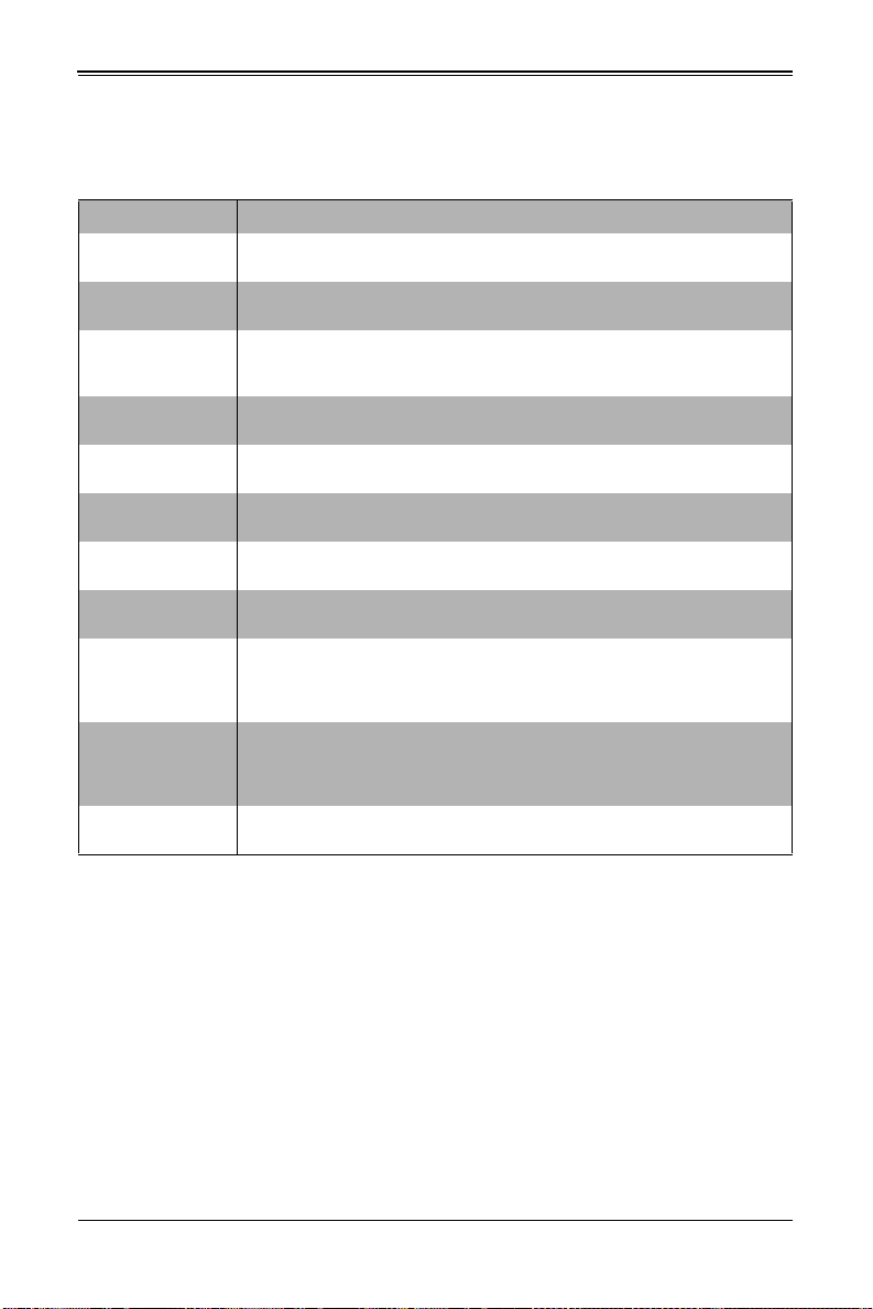
SBI-7127R-S6 Blade Module User’s Manual
5-6 Event Logs Setup
Table 5-12. Event Logs Menu
Menu Option Description
Change SMBIOS
Event Log Settings
SMBIOS Event
Log
Erase Event Log
Runtime Error
Logging Support
Memory Corr.
Error Support
PCI Error Logging
Support
When Log is Full
Log System Boot
Event
MECI
METW
View SMBIOS Event
Log
This submenu allows you to change the SMBIOS Event Log configuration
settings.
This setting allows you to Enable or Disable SMBIOS Event Logging.
Use this setting for erasing the SMBIOS Event Log. Erasing is done prior to any
logging activation during reset. Options are No, Yes Next Reset and Yes Every
Reset.
This setting allows you to Enable or Disable runtime error logging support.
This setting allows you to enter the memory correctable error threshold value.
This setting allows you to Enable or disable PCI error logging for your system.
Use this setting to choose options for reactions to a full SMBIOS Event Log.
Options include Do Nothing and Erase Immediately.
Use this setting to choose the option to Enable or Disable logging of system
boot events.
This setting (Multiple Event Count Increment) is used to select the number of
occurrences of a duplicate event that must pass before the multiple-event
counter associated with the log entry is updated. This is specified as a numeric
value in the range of 1 to 255. The default for this setting is set to 1.
This setting (Multiple Event Time Window) is used to select the number of
minutes which must pass between duplicate log entries that utilize a
multiple-event counter. The value ranges from 0 to 99 minutes. The default for
this setting is set to 60.
Selecting this option displays the SMIBIOS Event Log for viewing.
5-14
Page 71

5-7 IPMI Setup
Menu Option Description
IPMI Information
System Event Log
SEL Components
Erase SEL
When SEL is Full
Log EFI Status
Codes
BMC Network
Configuration
BMC Network
Configuration
Information
Update IPMI LAN
Configuration
Configuration
Address Source
IPMI Firmware Revision and IPMI Status information are statically displayed at
the top of this menu.
Selecting this submenu displays settings for changing the SEL Event Log
configuration. Note: all values changed here do not t ake ef fect until the system is
restarted.
Change this setting to Enable or Disable all features of the System Event
Logging during boot-up.
Use this setting for erasing the SEL. Options are No, Yes On Next Reset and Y es
On Every Reset.
Use this setting to choose options for reactions to a full S EL. Opt ions i nclude Do
Nothing and Erase Immediately.
Use this setting to Enable or Disable logging of EFI status codes, log only error
codes or only progress codes
Use this submenu to configure BMC network parameters.
The submenu contains static display information for the Station IP Address,
Subnet Mask, Station MAC Address and Gateway IP Address.
Specify Yes or No for the BIOS to use this setting for IPMI in the next boot-up.
This setting allows you to configure LAN channel parameters Statically or
Dynamically (by BIOS or BMC). Unspecified option will not modify any BMC
network parameters during the BIOS phase. Options are DHCP (dynamic) or
Static.
Chapter 5: BIOS
Table 5-13. IPMI Menu
5-15
Page 72
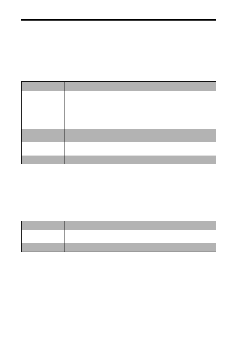
SBI-7127R-S6 Blade Module User’s Manual
5-8 Boot
Choose Boot from the 16 Mb SPI Flash EEPROM with AMI® BIOS BIOS Setup Utility
main menu with the arrow keys to bring up the B
OOT SETUP menu. Security setting
options are displayed by highlighting the setting using the arrow keys and pressing
<E
NTER>. All Security BIOS settings are described in Table 5-14 below.
Table 5-14. Boot Setup Menu Options
Menu Option Description
This sub-menu feature allows you to specify the sequence of priority for the boot
device (such as hard disk drives, USB devices, CD-ROM drives, Network drives
and so on). The menu options are for 1st Boot Device, 2nd Boot Device and 3rd
Boot Device Priority
Network Device
BBS Priorities
USB Device BBS
Priorities
Delete Boot Option This submenu allows you to remove an EFI boot option form the boot order.
Boot device, 4th Boot Device and so on. Each numbe red b oot device ca n be se t
to a specific device installed in your system or to Disabled.
NOTE: A device enclosed in parent hesis has been disabled in the corresponding
type menu.
This submenu allows you to set the order of the legacy devices in this group for
setting the boot order.
This submenu allows you to set the order of the legacy devices in this group for
setting the boot order.
5-9 Security
Choose Security from the BIOS Setup main menu with the arrow keys to bring up the
S
ECURITY SETUP menu. Security setting options are displayed by highlighting the setting
using the arrow keys and pressing <E
Table 5-15 below.
NTER>. All Security BIOS settings are described in
Table 5-15. Security Menu Options
Menu Option Description
Administrator
Password
User Password This allows you to create user password for the system.
This allows you to create an administrator password for the system.
5-16
Page 73
Chapter 5: BIOS
5-10 Save & Exit
Choose SAVE & EXIT from the 16 Mb SPI Flash EEPROM with AMI® BIOS BIOS Setup
Utility main menu with the arrow keys to display the S
BIOS settings are described in Table 5-16 below.
Table 5-16. Exit Menu Options
Menu Option Description
Discard Changes and
Exit
Save Changes and
Exit
Save Changes
Discard Changes
Restore Defaults
Save as Users
Defaults
Restore User
Defaults
Boot Override
Highlight this item and hit <E
any changes you may have made. Any changes you have made to the BIOS
Setup will not take effect upon system bootup.
Highlight this item and hit <ENTER> to save any changes you made and to exit
the BIOS Setup utility. The system will reboot and implement the changes you
have made to the BIOS Setup.
Highlight this item and hit <E
setup options.
Highlight this item and hit <ENTER> to discard (cancel) any changes you made.
You will remain in the Setup utility.
Highlight this item and hit <E
BIOS Setup. These are the safest settings to use and are designe d for maximum
system performance, but may not work best for all computer applications.
Highlight this item and hit <ENTER> to save changes done so far as user
defaults.
Highlight this item and hit <E
options.
For each boot device you have the option of saving the configuration for it and
exiting.
NTER> to exit the BIOS Setup utility without saving
NTER> to save changes done so far to any of the
NTER> to load the default settings for all items in the
NTER> to restore the user defaults to all the setup
AVE & EXIT SETUP menu. All Exit
5-17
Page 74

SBI-7127R-S6 Blade Module User’s Manual
Notes
5-18
Page 75

Appendix A
BIOS POST Codes
A-1 BIOS POST Messages
During the Power-On Self-T est (POST), the BIOS will check for problems. If a problem is
found, the BIOS will activate an alarm or display a message. The following is a list of
such BIOS messages.
Table A-1. BIOS POST Messages
BIOS Message Description
Failure Fixed Disk
Stuck key Stuck key on keyboard.
Keyboard error Keyboard not working.
Keyboard Controller Failed
Keyboard locked - Unlock key switch Unlock the system to proceed.
Monitor type does not match CMOS -
Run SETUP
Shadow Ram Failed at offset: nnnn
System RAM Failed at offset: nnnn
Extended RAM Failed at offset: nnnn
System battery is dead - Replace and
run SETUP
System CMOS checksum bad - Default
configuration used
System timer error The timer test failed. Requires repair of system board.
Real time clock error
Check date and time settings
Fixed disk is not working or not configured properly. Check to
see if fixed disk is attached properly. Run Setup. Find out if the
fixed-disk type is correctly identified.
Keyboard controller failed test. May require replacing keyboard
controller.
Monitor type not correctly identified in Setup
Shadow RAM failed at offset nnnn of the 64k block at which
the error was detected.
System RAM failed at offset nnnn of in the 64k block at which
the error was detected.
Extended memory not working or not configured properly at
offset nnnn.
The CMOS clock battery indicator shows the battery is dead.
Replace the battery and run Setup to reconfigure the system.
System CMOS has been corrupted or modified incorrectly,
perhaps by an application program that changes dat a stored in
CMOS. The BIOS installed Default Setup Values. If you do not
want these values, enter Setup and enter your own values. If
the error persists, check the system battery or contact your
dealer.
Real-Time Clock fails BIOS hardware test. May require board
repair.
BIOS found date or time out of range and reset the Real-Time
Clock. May require setting legal date (1991-2099).
A-1
Page 76

SBI-7427R-S3/T3 Blade Module User’s Manual
Table A-1. BIOS POST Messages (Continued)
BIOS Message Description
Previous POST did not complete successfully. POST loads
default values and offers to run Setup. If th e failure was caused
Previous boot incomplete - Default
configuration used
Memory Size found by POST differed
from CMOS
Diskette drive A error
Diskette drive B error
Incorrect Drive A type - run SETUP Type of floppy drive A: not correctly identified in Setup.
Incorrect Drive B type - run SETUP Type of floppy drive B: not correctly identified in Setup.
System cache error - Cache disabled
CPU ID: CPU socket number for Multi-Processor error.
EISA CMOS not writeable ServerBIOS2 test error: Cannot wr ite to EISA CMOS.
DMA Test Failed
Software NMI Failed
Fail-Safe Timer NMI Failed ServerBIOS2 test error: Fail-Safe T i mer takes too long.
device Address Conflict Address conflict for specified device.
Allocation Error for: device
CD ROM Drive CD ROM Drive identified.
Entering SETUP... Starting Setup program
Failing Bits: nnnn
Fixed Disk n Fixed disk n (0-3) identified.
Invalid System Configuration Data Problem with NVRAM (CMOS) data.
I/O device IRQ conflict I/O device IRQ conflict error.
PS/2 Mouse Boot Summary Screen: PS/2 Mouse installed.
by incorrect values and they are not corrected, the next boot
will likely fail. On systems with control of wait states, improper
Setup settings can also terminate POST and cause this error
on the next boot. Run Setup and verify that the waitstate
configuration is correct. This error is cleared the next time the
system is booted.
Memory size found by POST differed from CMOS.
Drive A: or B: is present but fails the BI OS POST disket te test s.
Check to see that the drive is defined with the proper diskette
type in Setup and that the diskette drive is attached correctly.
RAM cache failed and BIOS disabled the cache. On older
boards, check the cache jumpers. You may have to replace the
cache. See your dealer. A disabled cache slows system
performance considerably.
ServerBIOS2 test error: Cannot write to extended DMA (Direct
Memory Access) registers.
ServerBIOS2 test error: Cannot generate software NMI
(Non-Maskable Interrupt).
Run ISA or EISA Configuration Utility to resolve resource
conflict for the specified device.
The hex number nnnn is a map of the bits at t he RAM address
which failed the memory test. Each 1 (one) in the map
indicates a failed bit. See errors 230, 231, or 232 above for
offset address of the failure in System, Extended, or Shadow
memory.
A-2
Page 77
Appendix A: BIOS POST Codes
Table A-1. BIOS POST Messages (Continued)
BIOS Message Description
nnnn kB Extended RAM Passed
nnnn Cache SRAM Passed
nnnn kB Shadow RAM Passed
nnnn kB System RAM Passed
One or more I2O Block Storage
Devices were excluded from the Setup
Boot Menu
Operating system not found
Parity Check 1 nnnn
Parity Check 2 nnnn
Press <F1> to resume, <F2> to Setup,
<F3> for previous
Press <F2> to enter Setup
PS/2 Mouse: PS/2 mouse identified.
Run the I2O Configuration Utility
System BIOS shadowed System BIOS copied to shadow RAM.
UMB upper limit segment address:
nnnn
Video BIOS shadowed Video BIOS successfully copied to shadow RAM.
Where nnnn is the amount of RAM in kilobytes successfully
tested.
Where nnnn is the amount of system cache in kilobytes
successfully tested.
Where nnnn is the amount of shadow RAM in kilobytes
successfully tested.
Where nnnn is the amount of system RAM in kilobytes
successfully tested.
There was not enough room in the IPL table to display all
installed I2O block-storage devices.
Operating system cannot be located on either drive A: or drive
C:. Enter Setup and see if fixed disk and drive A: are properly
identified.
Parity error found in the system bus. BIOS attempts to locate
the address and display it on the screen. If it cannot locate the
address, it displays ????. Parity is a method for checking
errors in binary data. A parity error indicates that some data
has been corrupted.
Parity error found in the I/O bus. BIOS attempts to locate the
address and display it on the screen. If it cannot locate the
address, it displays ????.
Displayed after any recoverable error message. Press <F1> to
start the boot process or <F2> to enter Setup and change the
settings. Press <F3> to display the previous screen (usually an
initialization error of an Option ROM, i.e., an add-on card).
Write down and follow the information shown on the screen.
Optional message displayed during POST. Can be turned off in
Setup.
One or more unclaimed block storage devices have the
Configuration Request bit set in the LCT. Run an I2O
Configuration Utility (e.g. the SAC utility).
Displays the address nnnn of the upper limit of Upper
Memory Blocks, indicating released segments of the BIOS
which can be reclaimed by a virtual memory manager.
A-2 BIOS POST Codes
This section lists the POST (Power-On Self-Test) codes for the 16 Mb SPI Flash
EEPROM with AMI® BIOS BIOS. POST codes are divided into two categories:
recoverable and terminal.
A-3
Page 78

SBI-7427R-S3/T3 Blade Module User’s Manual
Recoverable POST Errors
When a recoverable type of error occurs during POST, the BIOS will display an POST
code that describes the problem. BIOS may also issue one of the following beep codes:
• One long and two short beeps – video configuration error
• One repetitive long beep – no memory detected
Terminal POST Errors
If a terminal type of error occurs, BIOS will shut down the system. Before doing so,
BIOS will write the error to port 80h, attempt to initialize video and write the error in the
top left corner of the screen.
The following is a list of codes that may be written to port 80h.
Table A-2. Terminal POST Errors
Post Code Description
02h Verify Real Mode
03h Disable Non-Maskable Interr upt (NMI)
04h Get CPU type
06h Initialize system hardware
07h Disable shadow and execute code from the ROM.
08h Initialize chipset with initial POST values
09h Set IN POST flag
0Ah Initialize CPU registers
0Bh Enable CPU cache
0Ch Initialize caches to initial POST values
0Eh Initialize I/O component
0Fh Initialize the local bus IDE
10h Initialize Power Management
11h Load alternate registers with initial POST values
12h Restore CPU control word during warm boot
13h Initialize PCI Bus Mastering devices
14h Initialize keyboard controller
16h 1-2-2-3 BIOS ROM checksum
17h Initialize cache before memory Auto size
18h 8254 timer initialization
1Ah 8237 DMA controller initialization
1Ch Reset Programmable Interrupt Controller
20h 1-3-1-1 Test DRAM ref resh
A-4
Page 79

Appendix A: BIOS POST Codes
Table A-2. Terminal POST Errors (Continued)
Post Code Description
22h 1-3-1-3 Test 8742 Keyboard Controller
28h Auto size DRAM
29h Initialize POST Memory Manager
2Ah Clear 512 kB base RAM
2Ch 1-3-4-1 RAM failure on address line xxxx*
2Eh 1-3-4-3 RAM failure on data bits xxxx* of low byte of memory bus
2Fh Enable cache before system BIOS shadow
32h Test CPU bus-clock frequency
33h Initialize Phoenix Dispatch Manager
36h Warm start shut down
38h Shadow system BIOS ROM
3Ah Auto size cache
3Ch Advanced configuration of chipset registers
3Dh Load alternate registers with CMOS values
41h Initialize extended memory for RomPilot
42h Initialize interrupt vectors
45h POST device initialization
46h 2-1-2-3 Check ROM copyright notice
47h Initialize I20 support
48h Check video configuration against CMOS
49h Initialize PCI bus and devices
4Ah Initialize all video adapters in system
4Bh QuietBoot start (optional)
4Ch Shadow video BIOS ROM
4Eh Display BIOS copyright notice
4Fh Initialize MultiBoot
50h Display CPU type and speed
51h Initialize EISA board
52h Test keyboar d
54h Set key click if enabled
55h Enable USB devices
58h 2-2-3-1 Test for unexpected interrupts
59h Initialize POST display service
5Ah Display prompt “Press F2 to enter SETUP”
5Bh Disable CPU cache
A-5
Page 80

SBI-7427R-S3/T3 Blade Module User’s Manual
Table A-2. Terminal POST Errors (Continued)
Post Code Description
5Ch Test RAM between 512 and 640 kB
60h Test extended memory
62h Test extended memory address lines
64h Jump to UserPatch1
66h Configure advanced cache registers
67h Initialize Multi Processor APIC
68h Enable external and CPU caches
69h Setup System Management Mode (SMM) area
6Ah Display external L2 cache size
6Bh Load custom defaults (optional)
6Ch Display shadow-area message
6Eh Display possible high address for UMB recovery
70h Display error messages
72h Check for configuration errors
76h Check for keyboard errors
7Ch Set up hardware interrupt vectors
7Dh Initialize Intelligent System Monitoring
7Eh Initialize coprocessor if present
80h Disable onboard Super I/O ports and IRQs
81h Late POST device initialization
82h Detect and install external RS232 ports
83h Configure non-MCD IDE controllers
84h Detect and install external parallel ports
85h Initialize PC-compatible PnP ISA devices
86h Re-initialize onboard I/O ports.
87h Configure Motherboard Configurable Devices (optional)
88h Initialize BIOS Data Area
89h Enable Non-Maskable Interrupts (NMIs)
8Ah Initialize Extended BIOS Data Area
8Bh Test and initialize PS/2 mouse
8Ch Initialize floppy controller
8Fh Determine number of ATA drives (optional)
90h Initialize hard-disk controllers
91h Initialize local-bus hard-disk controllers
92h Jump to UserPatch2
A-6
Page 81

Appendix A: BIOS POST Codes
Table A-2. Terminal POST Errors (Continued)
Post Code Description
93h Build MPTABLE for multi-processor boards
95h Install CD ROM for boot
96h Clear huge ES segment register
98h 1-2 Search for option ROMs. One long, two short beeps on check-sum failu re
99h Check for SMART Drive (optional)
9Ah Shadow option ROMs
9Ch Set up Power Management
9Dh Initialize security engine (optional)
9Eh Enable hardware interrupts
9Fh Determine number of ATA and SCSI drives
A0h Set time of day
A2h Check key lock
A4h Initialize typematic rate
A8h Erase F2 prompt
AAh Scan for F2 key stroke
ACh Enter SETUP
AEh Clear Boot flag
B0h Check for errors
B1h Inform RomPilot about the end of POST.
B2h POST done - prepare to boot operating system
B4h 1 One short beep before boot
B5h Terminate QuietBoot (optional)
B6h Check password (optional)
B7h Initialize ACPI BIOS
B9h Prepare Boot
BAh Initialize SMBIOS
BBh Initialize PnP Option ROMs
BCh Clear parity checkers
BDh Display MultiBoot menu
BEh Clear screen (optional)
BFh Check virus and backup reminders
C0h Try to boot with INT 19
C1h Initialize POST Error Manager (PEM)
C2h Initialize error logging
C3h Initialize error display function
A-7
Page 82
SBI-7427R-S3/T3 Blade Module User’s Manual
Table A-2. Terminal POST Errors (Continued)
Post Code Description
C4h Initialize system error handler
C5h PnPnd dual CMOS (optional)
C6h Initialize note dock (optional)
C7h Initialize note dock late
C8h Force check (optional)
C9h Extended checksum (optional)
CAh Redirect Int 15h to enable remote keyboard
CBh
CCh Redirect Int 10h to enable remote serial video
CDh Re-map I/O and memory for PCMCIA
CEh Initialize digitizer and display message
D2h Unknown interrupt
The following are for the boot block in Flash ROM:
Post Code Description
E0h Initialize the chipset
E1h Initialize the bridge
E2h Initialize the CPU
E3h Initialize system timer
E4h Initialize system I/O
E5h Check force recovery boot
E6h Checksum BIOS ROM
E7h Go to BIOS
E8h Set Huge Segment
E9h Initialize Multi Processor
EAh Initialize OEM special code
EBh Initialize PIC and DMA
ECh Initialize Memory type
EDh Initialize Memory size
EEh Shadow Boot Block
EFh System memory test
F0h Initialize interrupt vectors
F1h Initialize Run Time Clock
Redirect Int 13h to Memory Technologies Devices such as ROM, RAM, PCMCIA, and
serial disk
Table A-3. Boot Block Flash ROM Terminal POST Errors
A-8
Page 83

Appendix A: BIOS POST Codes
Table A-3. Boot Block Flash ROM Terminal POST Errors (Continued)
Post Code Description
F2h Initialize video
F3h Initialize System Management Manager
F4h Output one beep
F5h Clear Huge Segment
F6h Boot to Mini DOS
F7h Boot to Full DOS
If the BIOS detects error 2C, 2E, or 30 (base 512K RAM error), it displays an additional
word-bitmap (
means address line 1 (bit one set) has failed. “2E 1020" means data bits 12 and 5 (bits
12 and 5 set) have failed in the lower 16 bits. The BIOS also sends the bitmap to the
port-80 LED display. It first displays the checkpoint code, followed by a delay, the
high-order byte, another delay, and then the low order byte of the error. It repeats this
sequence continuously.
xxxx) indicating the address line or bits that failed. For example, “2C 0002”
A-9
Page 84

SBI-7427R-S3/T3 Blade Module User’s Manual
Notes
A-10
Page 85

Disclaimer
The products sold by Supermicro are not intended for and will not be used in life support
systems, medical equipment, nuclear facilities or systems, aircraft, aircraft devices,
aircraft/emergency communication devices or other critical systems whose failure to
perform be reasonably expected to result in significant injury or loss of life or
catastrophic property damage. Accordingly, Supermicro disclaims any and all liability,
and should buyer use or sell such products for use in such ultra-hazardous applications,
it does so entirely at its own risk. Furthermore, buyer agrees to fully indemnify, defend
and hold Supermicro harmless for and against any and all claims, demands, actions,
litigation, and proceedings of any kind arising out of or related to such ultra-hazardous
use or sale.
0-1
Page 86

SBI-7127R-S6 Blade Module User’s Manual
0-2
 Loading...