

Page 1
S
UPERMICR
R
CONTACT INFORMATION
• www.supermicro.com (Email: [email protected])
• Manuals: http://www.supermicro.com/support/manuals
• Drivers & Utilities: ftp://ftp.supermicro.com
• Safety: http://www.supermicro.com/about/policies/safety_information.cfm
PACKAGE CONTENTS
(Applies to single-pack only)
X9DRX+-F
QUICK REFERENCE GUIDE REV. 1.0A
• One (1) Supermicro Motherboard
• Six (6) Serial ATA Cables
• One (1) I/O Shield
MNL-1323-QRG REV. 1.0A
© 2012 Supermicro Computer Inc. All rights reserved. Reproduction of this document whether in part or in whole is strictly prohibited without Supermicro's written
consent. All Trademarks are property of their respective entities. All information provided is deemed accurate at the time of printing; however, it is not guaranteed.
This motherboard supports up to 512 GB of 240-pin Registered (RDIMM)/Load
Reduced (LRDIMM) ECC or up to 128 GB of Unbuffered (UDIMM) ECC/Non-ECC
DDR3 800/1066/1333/1600 MHz 4-channel (per CPU) memory in 16 DIMM slots.
Note: For memory optimization, use only DIMM modules that have been validated by Supermicro.
For the latest memory updates, please refer to our website at http://www.supermicro.com/
products/motherboard.
S-SATA0
S-SATA1
S-SATA2
S-SATA3
I-SATA0
FAN/PCH
SP1
JSD1
JPI2C1
JPW4
JITP2
BIOS
LED3
FAN8/CPU2
FAN7/CPU1
FAN6
FAN5
FAN1
FANA
FAN4
FAN3
FANB
JVRM_I2C2
JVRM_I2C1
JPG1
JPL1
JPB1
JWD1
JPW1
J4
JPW3
JPW2
3-SPGPIO3
3-SPGPIO1
3-SPGPIO2
JIPMI1
JF1
JI2C1
JI2C2
JL1
JOH1
JD1
JSTBY1
JTPM1
JBAT1
(IN X8)
KB/MOUSE
USB2/3
IPMI_LAN
TPM/PORT80
CPU2 Slot 7 PCI-E 3.0 x 8
CPU2 Slot 5 PCI-E 3.0 x 8
CPU1 Slot 3 PCI-E 3.0 x 8
CPU1 Slot 1 PCI-E 3.0 x 8
USB8/9
USB6/7
P2-DIMMG1
P2-DIMMH2
P2-DIMMH1
P2-DIMMG2
P2-DIMME2
P2-DIMME1
P2-DIMMF2
P2-DIMMF1
P1-DIMMD1
P1-DIMMC2
P1-DIMMC1
P1-DIMMD2
P1-DIMMA1
P1-DIMMA2
P1-DIMMB1
CPU1 Slot 2 PCI-E 3.0 x 8
CPU1 Slot 4 PCI-E 3.0 x 8
CPU2 Slot 6 PCI-E 3.0 x 8
CPU1 Slot 8 PCI-E 3.0 x 8
CPU2 Slot 9 PCI-E 3.0 x 8
CPU2 Slot 10 PCI-E 3.0 x 8
CPU2 Slot 11 PCI-E 2.0 x 4
P1-DIMMB2
COM2
UID
VGA
LAN2
LAN1
COM1
I-SATA2
I-SATA4
I-SATA1
I-SATA3
I-SATA5
JPT1
USB4
USB5
JITP1
LED1
BMC CTRL
LAN
CTRL
FAN2
LED2
JBT1
X9DRX+-F
Rev.
1.01
PCH
USB0/1
CPLD
BMC Firmware
Clock Chip
JPME1
JPME2
CPU1
CPU2
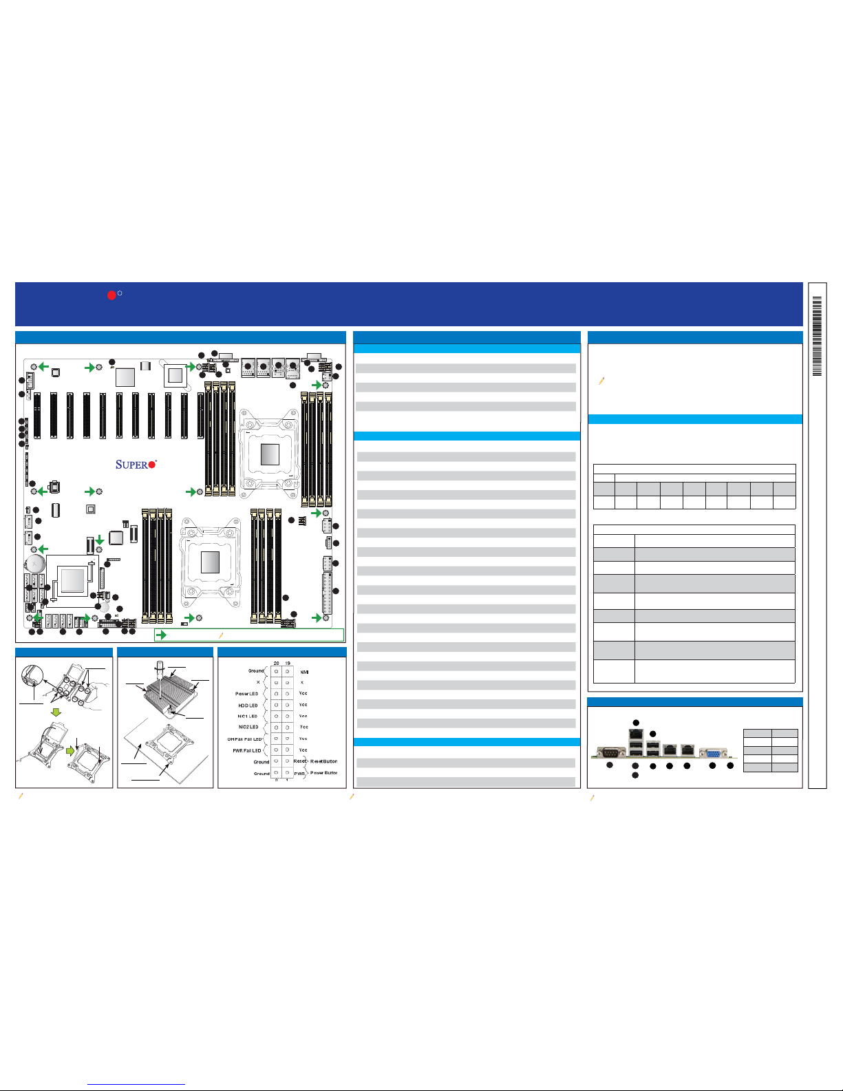
Insert the desired number of DIMMs into the memory slots, starting with P1-DIMMA1.
For memory to work properly, follow the tables below for memory population order.
Refer to the motherboard layout (at left) for the location of the DIMM slots.
Processors and their Corresponding Memory Modules
CPU# Corresponding DIMM Modules
CPU 1 P1-
DIMMA1
P1DIMMB1
P1DIMMC1
P1DIMMD1
P1DIMMA2
P1DIMMB2
P1DIMMC2
P1DIMMD2
CPU2 P2-
DIMME1
P2DIMMF1
P2DIMMG1
P2DIMMH1
P2DIMME2
P2DIMMF2
P2DIMMG2
P2DIMMH2
Processor and Memory Module Population for Optimal Performance
Number of
CPUs+DIMMs
CPU and Memory Population Confi guration Table
(For memory to work properly, please follow the instructions below.)
1 CPU &
2 DIMMs
CPU1
P1-DIMMA1/P1-DIMMB1
1 CPU &
4 DIMMs
CPU1
P1-DIMMA1/P1-DIMMB1, P1-DIMMC1/P1-DIMMD1
1 CPU &
5-8 DIMMs
CPU1
P1-DIMMA1/P1-DIMMB1, P1-DIMMC1/P1-DIMMD1 + Any memory pairs in P1DIMMA2/P1-DIMMB2/P1-DIMMC2/P1-DIMMD2 slots
2 CPUs &
4 DIMMs
CPU1 + CPU2
P1-DIMMA1/P1-DIMMB1, P2-DIMME1/P2-DIMMF1
2 CPUs &
6 DIMMs
CPU1 + CPU2
P1-DIMMA1/P1-DIMMB1/P1-DIMMC1/P1-DIMMD1, P2-DIMME1/P2-DIMMF1
2 CPUs &
8 DIMMs
CPU1 + CPU2
P1-DIMMA1/P1-DIMMB1/P1-DIMMC1/P1-DIMMD1, P2-DIMME1/P2-DIMMF1/P2DIMMG1/P2-DIMMH1
2 CPUs &
10-16 DIMMs
CPU1/CPU2
P1-DIMMA1/P1-DIMMB1/P1-DIMMC1/P1-DIMMD1, P2-DIMME1/P2-DIMMF1/P2DIMMG1/P2-DIMMH1 + Any memory pairs in P1, P2 DIMM slots
2 CPUs &
16 DIMMs
CPU1/CPU2
P1-DIMMA1/P1-DIMMB1/P1-DIMMC1/P1-DIMMD1, P2-DIMME1/P2-DIMMF1/
P2-DIMMG1/P2-DIMMH1,P1-DIMMA2/P1-DIMMB2/P1-DIMMC2/P1-DIMMD2, P2DIMME2/P2-DIMMF2/P2-DIMMG2/P2-DIMMH2
OPEN 1st
Connector Item # Description
COM1/COM2 1, 13 Backplane COM Port1/Front Accessible COM2 Header
Fan 1~4 42, 40, 49, 50 CPU/System 4-Pin Fan Headers
Fan 5~8 9, 11, 41, 47 CPU/System 4-Pin Fan Headers (Fan 7/8 CPU 1/2 Fans)
FanA, FanB 39, 28 CPU/System 4-Pin Fan Headers
FAN PCH 35 3-Pin PCH Fan Header
JD1 32 Speaker/Power LED Indicator
JF1 31 Front Panel Control Header
JIPMI1 14 4-pin External BMC I
2
C Header (for an IPMI Card)
JL1 27 Chassis Intrusion
JOH1 38 Overheat LED Indicator
JPI
2
C1 45 Power Supply SMBbus I2C Header
JPW1 43 ATX 24-Pin Power Connector
JPW2/3 44, 46 12V 8-Pin Power Connectors
JPW4 48 12V 4-Pin Power Connector (optional)
JSTBY1 20 3V Standby Power Header
JTPM1 36 TPM (Trusted Platform Module)/Port 80 Header
JSD1 25 SATA Device Power Connector
LAN1/LAN2 5, 6 G-bit Ethernet Ports 1/2
(IPMI) LAN 3 IPMI Dedicated LAN
(I)-SATA 0/1 24 Intel SB I-SATA 3.0 Connectors #0/1
(I)-SATA 2~5 23 Intel PCH SATA 2.0 Connectors 2~5 (Color: Black)
(S)-SATA 0~3 29 Intel SB S-SATA 2.0 Connectors #0~3
SP1 33 Onboard Buzzer (Internal Speaker)
3-SGPIO 1/2/3 26 Serial Link General Purpose I/O Headers
USB 0/1, 2/3 2, 4 Back Panel USB 0/1, 2/3
USB 4, 5 21, 22 Front Panel Type A USB Connections
USB 6/7, USB 8/9 30 Front Panel Accessible USB Connections
UID 8 UID (Unit Identifi cation) Switch
VGA 7 Backpanel VGA Port
Note: Item numbers are listed in counterclockwise order.
LED Item # Description Color/State Status
LED1 12 BMC Heartbeat LED Green: Blinking BMC Normal
LED2 37 Onboar d PWR L ED Green: On Main Power On
LED3 10 UID Switch LED
Motherboard Layout and Features
Jumpers, Connectors and LED Indicators
Back Panel IO Connectors
Memory Support
Jumpers
Connectors
LED Indicators
CPU Installation
Socket Keys
1.
2.
CPU Keys
Note: Graphics shown in this quick reference guide are for illustration only. Your components may or may not look exactly the same as drawings shown in this guide.
Note: Refer to Chapter 2 of the User Manual for detailed information on jumpers, connectors, and LED indicators.
Note: Refer to Chapter 2 of the User Manual for detailed information on memory support and CPU/
motherboard installation instructions.
= mounting hole
Heatsink Installation
DIMM Installation
Front Panel Control (JF1)
1
5
1
9
1
14
1
10
1
15
1
4
1
8
1
13
1
3
1
7
1
12
1
17
1
18
1
19
1
20
1
2
1
6
1
11
1
16
1
21
1
26
1
31
1
36
1
41
1
37
1
42
1
43
1
44
1
45
1
46
1
47
1
48
1
49
1
50
1
38
1
39
1
40
1
32
1
33
1
34
1
35
1
27
1
28
1
29
1
30
1
22
1
23
1
24
1
25
1
1
OPEN 1st
Screw #1
Screw #2
Screw #4
Motherboard
Screw #3
Mounting Hole
A
B
C
D
E
F
G
H
I
J
A. COM1 F. USB 3
B. USB 0 G. GLAN1
C. USB 1 H. GLAN2
D. IPMI LAN I. VGA
E. USB 2 J. UID
Jumper Item # Description Default
JBT1 34 Clear CMOS See Chpt. 2 in User Manual
JI
2
C1/JI2C2 18 SMB to PCI-E Slots Off (Disabled)
JPB1 17 BMC Enabled Pins 1-2 (Enabled)
JPG1 15 VGA Enabled Pins 1-2 (Enabled)
JPL1 16 GLAN1/GLAN2 Enable Pins 1-2 (Enabled)
JWD1 19 Watch Dog Timer Enable Pins 1-2 (Reset)
 Loading...