

Page 1

MEMORY CONFIGURATION
FOR
X11 UP/DP/MP MOTHERBOARDS
(FOR INTEL® 81XX/61XX/51XX/41XX/31XX-BASED PLATFORMS)
USER’S GUIDE
Revision 1.0c
1
Page 2

Acknowledgements
Memory tables listed on Page 4 and Page 5 of this document are extracted from Section 7.5 and Section 7.6 of Intel's
Xeon-SP Design Guide Rev . 1.17, 12/2016. Intel is the rightful owner of these memory tables and the copyright thereof.
Super Micro Computer, Inc. incorporates the memory tables into this document under a general licensing provision
between the two companies. The information provided in this document is for general reference only.
Disclaimer
The information in this user’s manual has been carefully reviewed and is believed to be accurate. The vendor assumes
no responsibility for any inaccuracies that may be contained in this document, and makes no commitment to update
or to keep current the information in this manual, or to notify any person or organization of the updates. Please Note:
For the most up-to-date version of this manual, please see our website at
www.supermicro.com.
Super Micro Computer, Inc. ("Supermicro") reserves the right to make changes to the product described in this manual
at any time and without notice. This product, including software and documentation, is the property of Supermicro and/
or its licensors, and is supplied only under a license. Any use or reproduction of this product is not allowed, except
as expressly permitted by the terms of said license.
IN NO EVENT WILL Super Micro Computer, Inc. BE LIABLE FOR DIRECT, INDIRECT, SPECIAL, INCIDENTAL,
SPECULA TIVE OR CONSEQUENTIAL DAMAGES ARISING FROM THE USE OR INABILITY TO USE THIS PRODUCT
OR DOCUMENT ATION, EVEN IF ADVISED OF THE POSSIBILITY OF SUCH DAMAGES. IN PARTICULAR, SUPER
MICRO COMPUTER, INC. SHALL NOT HAVE LIABILITY FOR ANY HARDWARE, SOFTWARE, OR DATA STORED
OR USED WITH THE PRODUCT, INCLUDING THE COSTS OF REPAIRING, REPLACING, INTEGRATING,
INSTALLING OR RECOVERING SUCH HARDWARE, SOFTWARE, OR DATA.
Any disputes arising between manufacturer and customer shall be governed by the laws of Santa Clara County in the
State of California, USA. The State of California, County of Santa Clara shall be the exclusive venue for the resolution
of any such disputes. Supermicro's total liability for all claims will not exceed the price paid for the hardware product.
Manual Revision 1.0c
Release Date: March 23, 2018
Unless you request and receive written permission from Super Micro Computer, Inc., you may not copy any part of this
document. Information in this document is subject to change without notice. Other products and companies referred
to herein are trademarks or registered trademarks of their respective companies or mark holders.
Copyright © 2018 by Super Micro Computer, Inc.
All rights reserved.
Printed in the United States of America
2
Page 3

DIMM Population Guidelines
Memory Support for the X11 UP/DP/MP Motherboards
This document provides the user with an easy-to-use guide for proper memory confi guration
and installation for the X11 UP/DP/MP (Socket P/Socket P0) Motherboards utilizing
RDIMM/3DS RDIMM/LRDIMM/3DS LRDIMM memory modules. To ensure proper memory
installation, please follow the information and instructions listed below.
1 ESD Precautions
Electrostatic Discharge (ESD) can damage electronic com ponents including memory modules.
T o avoid damaging your DIMM modules, it is important to handle it very carefully. The following
measures are generally suffi cient to protect your equipment from ESD.
Precautions
Use a grounded wrist strap designed to prevent static discharge.
•
• Handle the memory module by its edges only.
• Put the memory modules into the antistatic bags when not in use.
• Check the Supermicro website for recommended memory modules
2 Memory Support
The X11 UP/DP/MP motherboard supports 3DS LRDIMM (3DS Load Reduced DIMM)/
LRDIMM (Load Reduced DIMM)/3DS RDIMM (3DS Registered DIMM)/RDIMM (Registered
DIMM), DDR4 (288-pin) ECC 2133/2400/2666 MHz memory modules. Refer to the following
tables for detailed information on memory support for the X11 UP/DP/MP motherboards.
3
Page 4
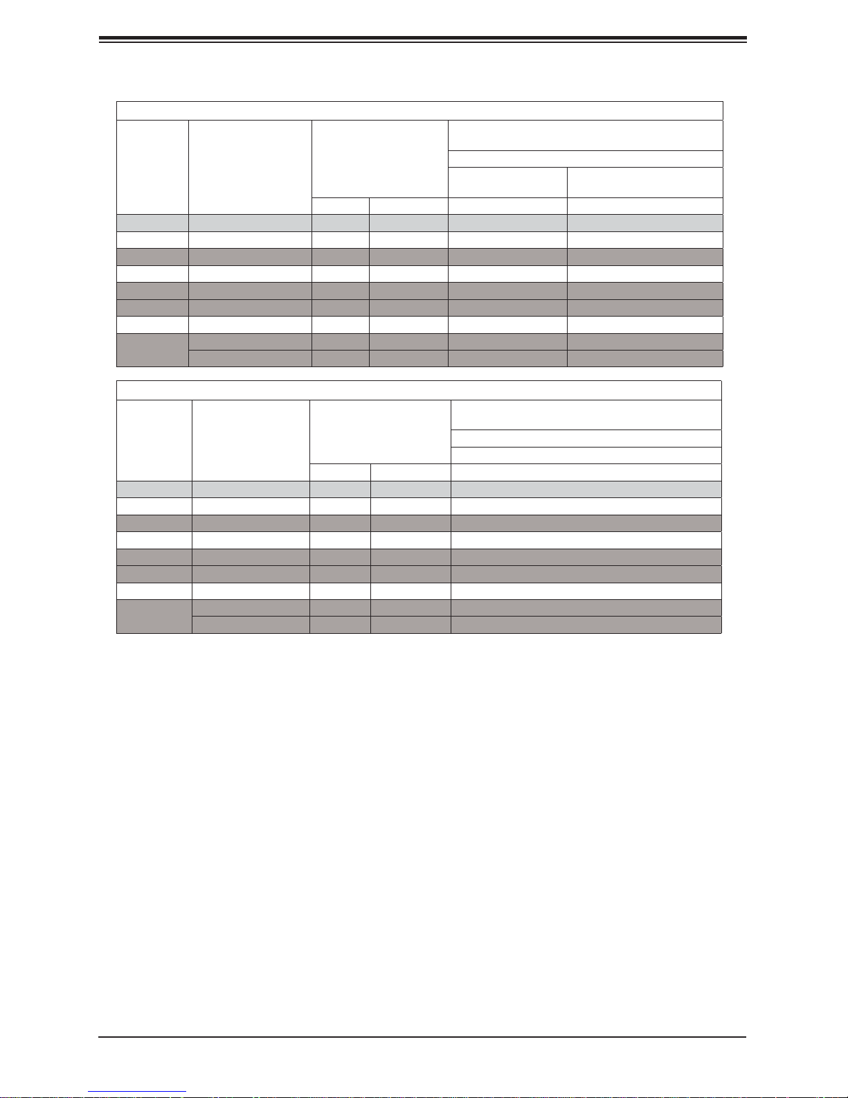
Supermicro Memory Confi guration User Guide for the X11 Series Motherboards
DDR4 Memory Support (for 2-Slot Per-Channel Confi guration)
Speed (MT/s); Voltage (V); Slots per Channel
(SPC) and DIMMs per Channel (DPC)
Type
RDIMM SRx4 8 GB 16 GB 2666 2666
RDIMM SRx8 4 GB 8 GB 2666 2666
RDIMM DRx8 8 GB 16 GB 2666 2666
RDIMM DRx4 16 GB 32 GB 2666 2666
RDIMM 3Ds QRX4 N/A 2H-64GB 2666 2666
RDIMM 3Ds 8RX4 N/A 4H-128GB 2666 2666
LRDIMM QRx4 32 GB 64 GB 2666 2666
LRDIMM
3Ds
Ranks Per DIMM and
Data Width
QRX4 N/A 2H-64GB 2666 2666
8Rx4 N/A 4H-128 GB 2666 2666
DIMM Capacity (GB)
1DPC (1-DIMM per
Channel)
4 Gb 8 Gb 1.2 V 1.2 V
DDR4 Memory Support (for 1-Slot Per-Channel Confi guration)
Speed (MT/s); Voltage (V); Slots per Channel
Type
RDIMM SRx4 8 GB 16 GB 2666
RDIMM SRx8 4 GB 8 GB 2666
RDIMM DRx8 8 GB 16 GB 2666
RDIMM DRx4 16 GB 32 GB 2666
RDIMM 3Ds QRX4 N/A 2H-64GB 2666
RDIMM 3Ds 8RX4 N/A 4H-128GB 2666
LRDIMM QRx4 32 GB 64 GB 2666
LRDIMM
3Ds
Ranks Per DIMM
and Data Width
QRX4 N/A 2H-64GB 2666
8Rx4 N/A 4H-128 GB 2666
DIMM Capacity (GB)
4 Gb 8 Gb 1.2 V
(SPC) and DIMMs per Channel (DPC)
2 Slots per Channel
2DPC (2-DIMM per Channel)
1 Slot per Channel
1DPC (1-DIMM per Channel)
3 Memory Installation Sequence
Memory modules for the X11 UP/DP/MP motherboards are populated using the "Fill First"
method. The blue memory slot of each channel is considered the "fi rst DIMM module" of
the channel, and the black slot, the second module of the channel. When installing memory
modules, be sure to populate the blue memory slots fi rst and then populate the black slots.
To maximize memory capacity and performance, please populate all DIMM slots on the
motherboard, including all blue slots and black slots.
4 General Memory Population Requirements
1. Be sure to use the memory modules of the same type and speed on the motherboard.
Mixing of memory modules of different types and speeds is not allowed.
2. Using unbalanced memory topology such as populating two DIMMs in one channel while
populating one DIMM in another channel on the same motherboard will result in reduced
memory performance.
4
Page 5
DIMM Population Guidelines
3. Populating memory slots with a pair of DIMM modules of the same type and size will
result in interleaved memory, which will improve memory performance.
5 DIMM Population Guidelines for Optimal Performance
For optimal memory performance, follow the instructions listed in the tables below when
populating memory modules.
5.1 Key Parameters for DIMM Confi guration
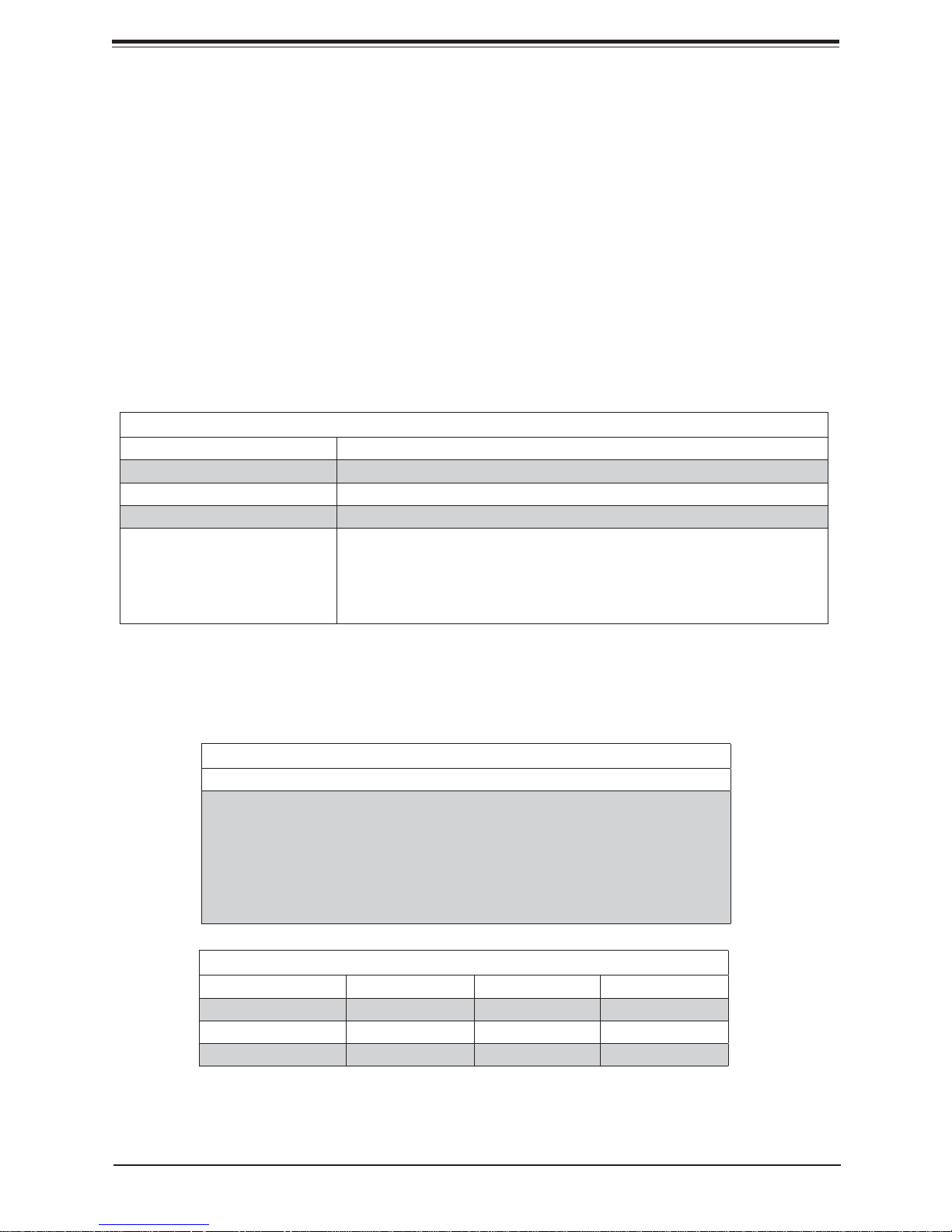
Key Parameters for DIMM Confi gurations
Parameters Possible Values
Number of Channels 1, 2, 3, 4, 5, or 6
Number of DIMMs per Channel 1DPC (1 DIMM Per Channel) or 2DPC (2 DIMMs Per Channel)
DIMM Type RDIMM (w/ECC), 3DS RDIMM, LRDIMM, 3DS LRDIMM
DIMM Construction • non-3DS RDIMM Raw Cards: A/B (2Rx4), C (1Rx4), D (1Rx8), E (2Rx8)
• 3DS RDIMM Raw Cards: A/B (4Rx4)
• non-3DS LRDIMM Raw Cards: D/E (4Rx4)
• 3DS LRDIMM Raw Cards: A/B (8Rx4)
5.2 DIMM Mixing Guidelines
General DIMM Mixing Guidelines
DIMM Mixing Rules
• All DIMMs must be all DDR4 DIMMs.
• x4 and x8 DIMMs can be mixed in the same channel.
• Mixing of LRDIMMs and RDIMMs is not allowed in the same channel, across different
channels, and across different sockets.
• Mixing of non-3DS and 3DS LRDIMM is not allowed in the same channel, across
different channels, and across different sockets.
Mixing of DIMM Types within a Channel
DIMM Types RDIMM LRDIMM 3DS LRDIMM
RDIMM Allowed Not Allowed Not Allowed
LRDIMM Not Allowed Allowed Not Allowed
3DS LRDIMM Not Allowed Not Allowed Allowed
5
Page 6
Supermicro Memory Confi guration User Guide for the X11 Series Motherboards
5.3 Memory Population Tables for the X11UP Motherboards
For your system memory to work properly, please follow the memory population tables
below to install your memory modules on the X11UP motherboard. These memory
population tables were created based on the general memory population guidelines
provided by Intel to support Supermicro's X11UP motherboards.
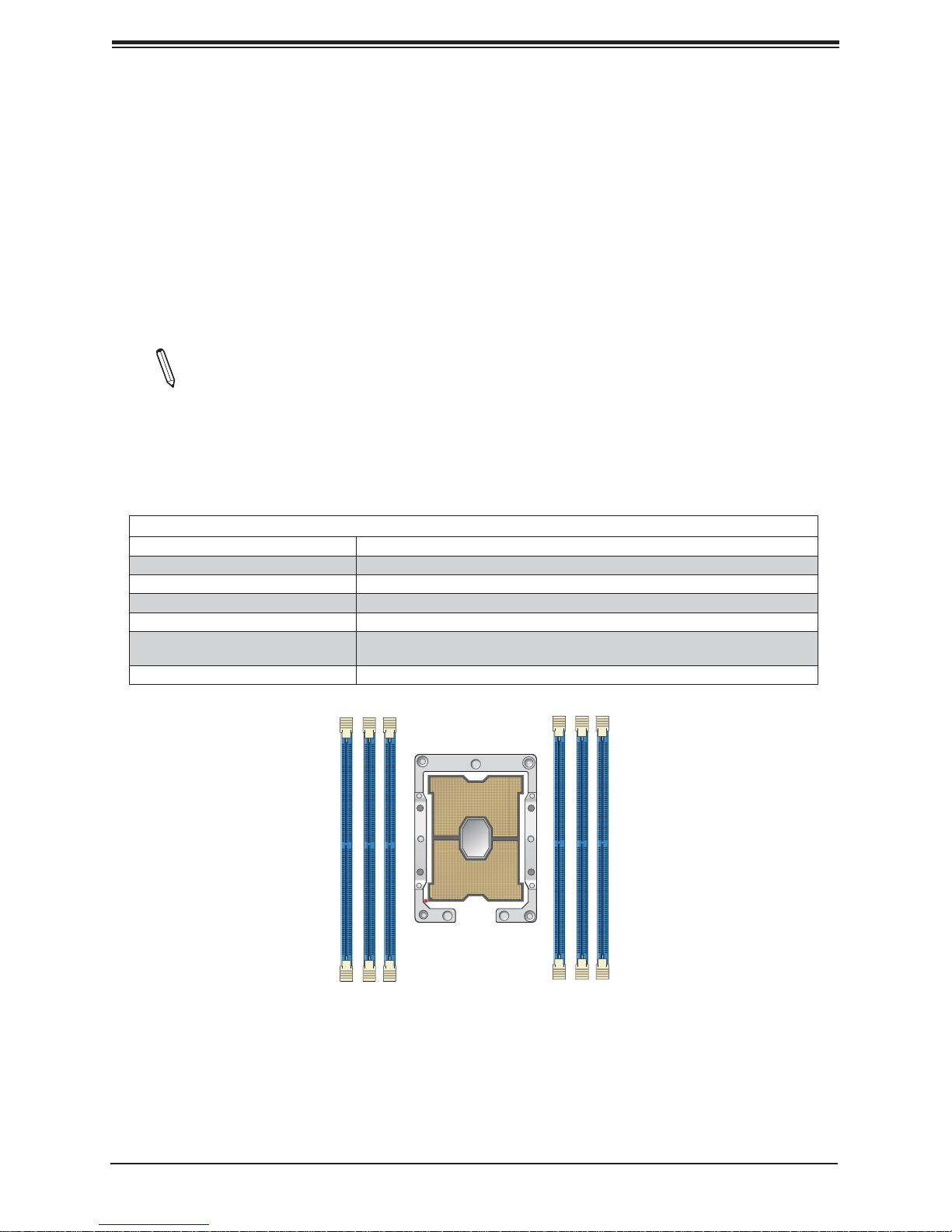
5.3.1 Memory Population for the X11UP Motherboards with 6 DIMM Slots
Onboard
Note 1. Unbalanced memory confi guration decreases memory performance and is not
recommended for Supermicro motherboards.
Note 2. The following memory population table supports Supermicro's X11UP motherboards with 6 DIMM memory slots onboard, such as X11SPW-TF/CTF, X11SPM-F/
TF/TPF, and X11SPG-TF.
Memory Population Tables for the X11UP Motherboard w/6 DIMM Slots Onboard
Memory Population Sequence
1 DIMM DIMMA1
2 DIMMs DIMMA1/DIMMD1
3 DIMMs DIMMC1/DIMMB1/DIMMA1
4 DIMMs DIMMB1/DIMMA1/DIMMD1/DIMME1
(Unbalanced: not recommended)
5 DIMMs
6 DIMMs DIMMC1/DIMMB1/DIMMA1/DIMMD1/DIMME1/DIMMF1
DIMMC1/ DIMMB1/DIMMA1/DIMMD1/DIMME1
DIMMA1
DIMMC1
DIMMB1
DIMMD1
DIMME1
DIMMF1
6
Page 7
DIMM Population Guidelines
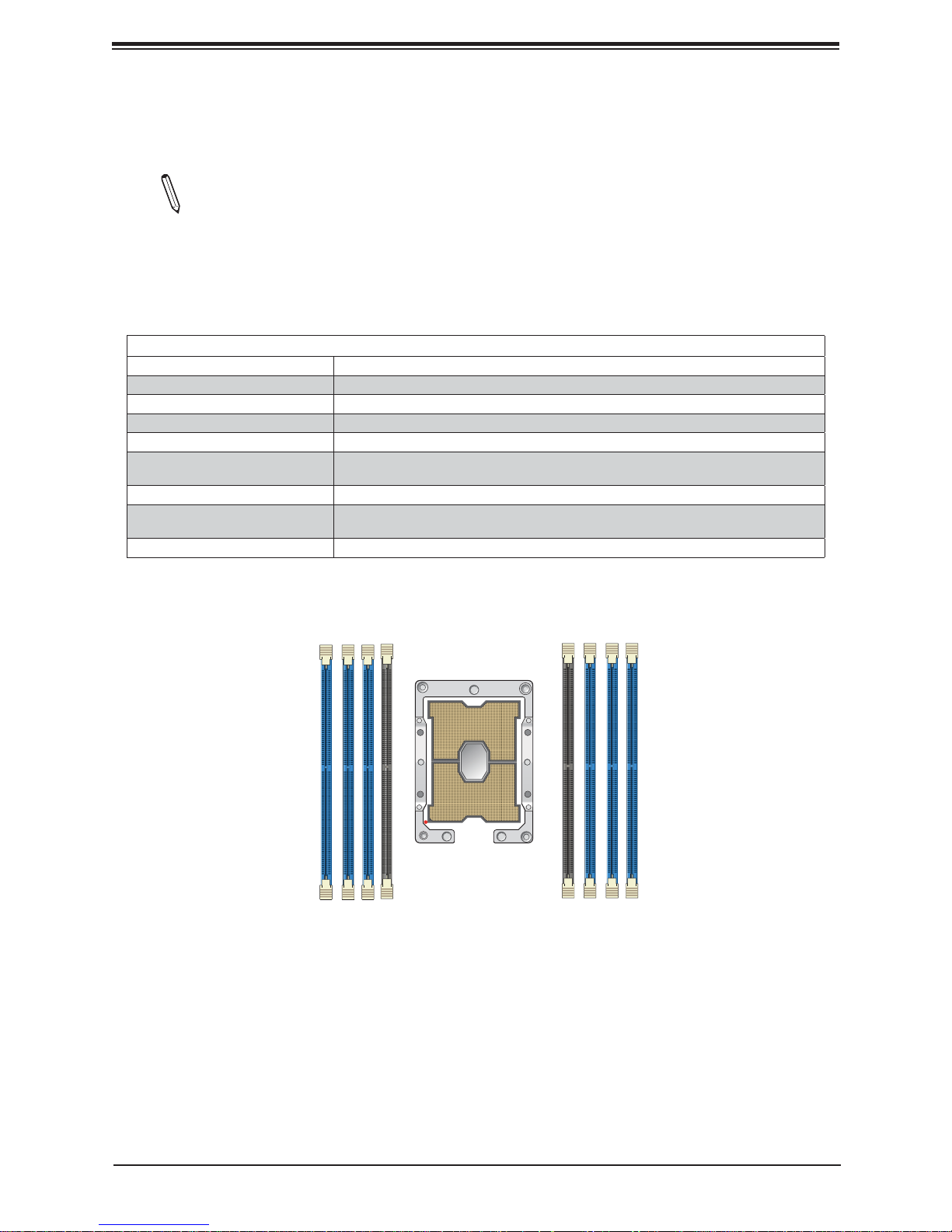
5.3.2 Memory Population for the X11UP Motherboards with 8 DIMM Slots
Onboard
Note 1. Unbalanced memory confi guration decreases memory performance and is not
recommended for Supermicro motherboards.
Note 2. The following memory population table supports Supermicro's X11UP motherboards with 8 DIMM memory slots onboard, such as X11SPi-TF, X11SPL-F, and
X11SPH-NCTF/NCTPF.
Memory Population Table for the X11UP Motherboard w/8 DIMM Slots Onboard
Memory Population Sequence
1 DIMM DIMMA1
2 DIMMs DIMMA1/DIMMD1
3 DIMMs DIMMC1/DIMMB1/DIMMA1
4 DIMMs DIMMB1/DIMMA1/DIMMD1/DIMME1
(Unbalanced: not recommended)
5 DIMMs
6 DIMM DIMMC1/DIMMB1/DIMMA1/DIMMD1/DIMME1/DIMMF1
7 DIMMs
(Unbalanced: not recommended)
8 DIMMs DIMMC1/DIMMB1/DIMMA1/DIMMA2/DIMMD2/DIMMD1/DIMME1/DIMMF1
DIMMC1/ DIMMB1/DIMMA1/DIMMD1/DIMME1
DIMMC1/DIMMB1/DIMMA1/DIMMA2/DIMMD1/DIMME1/DIMMF1
DIMMC1
DIMMA1
DIMMA2
DIMMB1
DIMMD1
DIMME1
DIMMD2
DIMMF1
7
Page 8
Supermicro Memory Confi guration User Guide for the X11 Series Motherboards
5.4 Memory Population Tables for the X11DP Motherboards
For your system memory to work properly, please follow the memory population tables
below to install your memory modules on the X11DP motherboard. These memory
population tables were created based on the general memory population guidelines
provided by Intel to support Supermicro's X11DP motherboards.
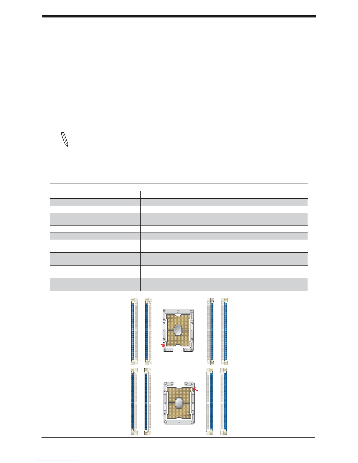
5.4.1 Memory Population for the X11DP Motherboards with 8 DIMM Slots
Onboard
Note 1. Unbalanced memory confi guration decreases memory performance and is not
recommended for Supermicro motherboards.
Note 2. The following memory population table supports Supermicro's X11DP motherboards with 8 DIMM memory slots onboard, such as X11DPL-i.
Memory Population Table for the X11DP Motherboard w/8 DIMM Slots Onboard
When 1 CPU is used: Memory Population Sequence
1 CPU & 1 DIMM CPU1: P1-DIMMA1
1 CPU & 2 DIMMs CPU1: P1-DIMMA1/P1-DIMMD1
(Unbalanced: not recommended)
1 CPU & 3 DIMMs
1 CPU & 4 DIMMs CPU1: P1-DIMMB1/P1-DIMMA1/P1-DIMMD1/P1-DIMME1
When 2 CPUs are used: Memory Population Sequence
2 CPUs & 2 DIMMs
2 CPUs & 4 DIMMs
2 CPUs & 6 DIMMs
2 CPUs & 8 DIMMs
CPU1: P1-DIMMB1/P1-DIMMA1/P1-DIMMD1
CPU1: P1-DIMMA1
CPU2: P2-DIMMA1
CPU1: P1-DIMMA1/P1-DIMMD1
CPU2: P2-DIMMA1/P2-DIMMD1
CPU1: P1-DIMMB1/P1-DIMMA1/P1-DIMMD1/P1-DIMME1
CPU2: P2-DIMMA1/P2-DIMMD1
CPU1: P1-DIMMB1/P1-DIMMA1/P1-DIMMD1/P1-DIMME1
CPU2: P2-DIMMB1/P2-DIMMA1/P2-DIMMD1/P2-DIMME1
P2-DIMMB1
P2-DIMMA1
CPU2
Pin 1
P2-DIMMD1
P2-DIMME1
P1-DIMME1
P1-DIMMD1
CPU1
8
Pin 1
P1-DIMMB1
P1-DIMMA1
Page 9
DIMM Population Guidelines
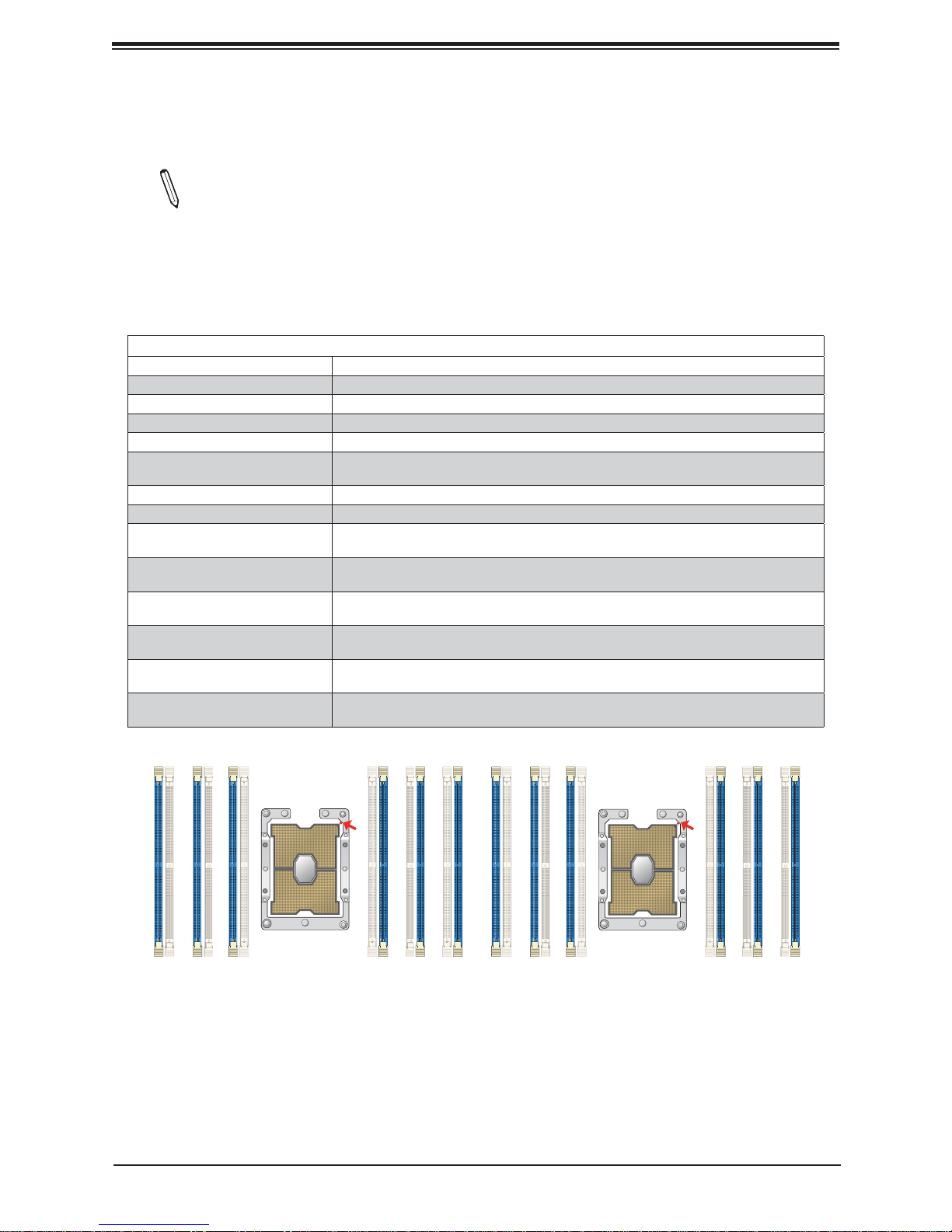
5.4.2.1 Memory Population for the X11DP Motherboards with 12 DIMM Slots
Onboard
Note 1. Unbalanced memory confi guration decreases memory performance and is not
recommended for Supermicro motherboards.
Note 2. The following memory population table supports Supermicro's X11DP motherboards with 12 DIMM memory slots onboard, such as X11DDW-L/NT, X11DPFR-S(N),
X11DGQ, X11DPFF-SN and X11DSN-TS.
Memory Population Tables for the X11DP Motherboard w/12 DIMM Slots Onboard
When 1 CPU is used: Memory Population Sequence
1 CPU & 1 DIMM CPU1: P1-DIMMA1
1 CPU & 2 DIMMs CPU1: P1-DIMMA1/P1-DIMMD1
1 CPU & 3 DIMMs CPU1: P1-DIMMC1/P1-DIMMB1/P1-DIMMA1
1 CPU & 4 DIMMs CPU1: P1-DIMMB1/P1-DIMMA1/P1-DIMMD1/P1-DIMME1
1 CPU & 5 DIMMs
(Unbalanced: not recomended)
1 CPU & 6 DIMM CPU1: P1-DIMMC1/P1-DIMMB1/P1-DIMMA1/P1-DIMMD1/P1-DIMME1/P1-DIMMF1
When 2 CPUs are used: Memory Population Sequence
2 CPUs & 2 DIMMs
2 CPUs & 4 DIMMs
2 CPUs & 6 DIMMs
2 CPUs & 8 DIMMs
2 CPUs & 10 DIMMs
2 CPUs & 12 DIMMs
CPU1: P1-DIMMC1/P1-DIMMB1/P1-DIMMA1/P1-DIMMD1/P1-DIMME1
CPU1: P1-DIMMA1
CPU2: P2-DIMMA1
CPU1: P1-DIMMA1/P1-DIMMD1
CPU2: P2-DIMMA1/P2-DIMMD1
CPU1: P1-DIMMC1/P1-DIMMB1/P1-DIMMA1
CPU2: P2-DIMMC1/P2-DIMMB1/P2-DIMMA1
CPU1: P1-DIMMB1/P1-DIMMA1/P1-DIMMD1/P1-DIMME1
CPU2: P2-DIMMB1/P2-DIMMA1/P2-DIMMD1/P2-DIMME1
CPU1: P1-DIMMC1/P1-DIMMB1/P1- DIMMA1/P1-DIMMD1/P1-DIMME1/P1-DIMMF1
CPU2: P 2-DIMMB1/P2-DIMMA1/P2-DIMMD1/P2-DIMME1
CPU1: P1-DIMMC1/P1-DIMMB1/P1-DIMMA1/P1-DIMMD1/P1-DIMME1/P1-DIMMF1
CPU2: P2-DIMMC1/P2-DIMMB1/P2-DIMMA1/P2-DIMMD1/P2-DIMME1/P2-DIMMF1
P2-DIMME1
P2-DIMMF1
P2-DIMMD1
CPU2
Pin 1
P2-DIMMA1
P2-DIMMB1
P2-DIMMC1
P1-DIMME1
P1-DIMMF1
9
P1-DIMMD1
CPU1
Pin 1
P1-DIMMB1
P1-DIMMA1
P1-DIMMC1
Page 10
Supermicro Memory Confi guration User Guide for the X11 Series Motherboards
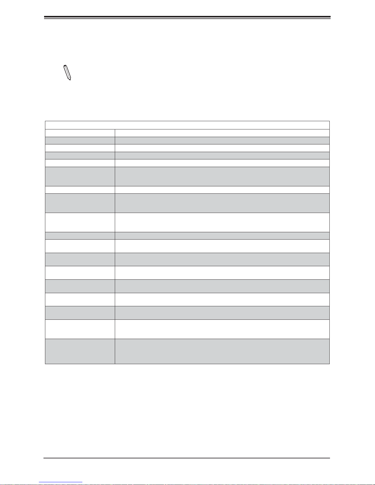
5.4.3 Memory Population for the X11DP Motherboards with 16 DIMM Slots
Onboard
Note 1. Unbalanced memory confi guration decreases memory performance and is not
recommended for Supermicro motherboards. Note 2. The following memory popula-
tion table supports Supermicro's X11DP motherboards with 16 DIMM memory slots
onboard, such as X1 1DPi-N(T), X1 1DPT-PS, X11DPU-X(LL), X11DPH-i/T(q), X11DPG-
QT, X11DAi-N, X11DPX-T, X11DPG-SN, X11DAC.
Memory Population Table for the X11DP Motherboard w/16 DIMM Slots Onboard
When 1 CPU is used: Memory Population Sequence
1 CPU & 1 DIMM CPU1: P1-DIMMA1
1 CPU & 2 DIMMs CPU1: P1-DIMMA1/P1-DIMMD1
1 CPU & 3 DIMMs CPU1: P1-DIMMC1/P1-DIMMB1/P1-DIMMA1
1 CPU & 4 DIMMs CPU1: P1-DIMMB1/P1-DIMMA1/P1-DIMMD1/P1-DIMME1
1 CPU & 5 DIMMs
(Unbalanced: not recom-
mended)
1 CPU & 6 DIMM CPU1: P1-DIMMC1/P1-DIMMB1/P1-DIMMA1/P1-DIMMD1/P1-DIMME1/P1-DIMMF1
1 CPU & 7 DIMMs
(Unbalanced: not recom-
mended)
1 CPU & 8 DIMMs
(Unbalanced: not recom-
mended)
When 2 CPUs are used: Memory Population Sequence
2 CPUs & 2 DIMMs
2 CPUs & 4 DIMMs
2 CPUs & 6 DIMMs
2 CPUs & 8 DIMMs
2 CPUs & 10 DIMMs
2 CPUs & 12 DIMMs
2 CPUs & 14 DIMMs
(Unbalanced: not recom-
mended)
2 CPUs & 16 DIMMs
(Unbalanced: not recom-
mended)
CPU1: P1-DIMMC1/P1-DIMMB1/P1-DIMMA1/P1-DIMMD1/P1-DIMME1
CPU1:P1-DIMMC1/P1-DIMMB1/P1-DIMMA1/P1-DIMMA2/P1-DIMMD1/P1-DIMME1/P1-DIMMF1
CPU1: P1-DIMMC1/P1-DIMMB1/P1-DIMMA1/P1-DIMMA2/P1-DIMMD2/P1-DIMMD1/P1DIMME1/P1-DIMMF1
CPU1: P1-DIMMA1
CPU2: P2-DIMMA1
CPU1: P1-DIMMA1/P1-DIMMD1
CPU2: P2-DIMMA1/P2-DIMMD1
CPU1: P1-DIMMC1/P1-DIMMB1/P1-DIMMA1
CPU2: P2-DIMMC1/P2-DIMMB1/P2-DIMMA1
CPU1: P1-DIMMB1/P1-DIMMA1/P1-DIMMD1/P1-DIMME1
CPU2: P2-DIMMB1/P2-DIMMA1/P2-DIMMD1/P2-DIMME1
CPU1: P1-DIMMC1/P1-DIMMB1/P1-DIMMA1/P1-DIMMD1/P1-DIMME1/P1-DIMMF1
CPU2: P2-DIMMB1/P2-DIMMA1/P2-DIMMD1/P2-DIMME1
CPU1: P1-DIMMC1/P1-DIMMB1/P1-DIMMA1/P1-DIMMD1/P1-DIMME1/P1-DIMMF1
CPU2: P2-DIMMC1/P2-DIMMB1/P2-DIMMA1/P2-DIMMD1/P2-DIMME1/P2-DIMMF1
CPU1: P1-DIMMC1/P1-DIMMB1/P1-DIMMA1/P1-DIMMA2/P1-DIMMD1/P1-DIMME1/P1-DIMMF1
CPU2: P2-DIMMC1/P2-DIMMB1/P2-DIMMA1/P2-DIMMA2/P2-DIMMD1/P2-DIMME1/P2-DIMMF1
CPU1: P1-DIMMC1/P1-DIMMB1/P1-DIMMA1/P1-DIMMA2/P1-DIMMD2/P1-DIMMD1/P1DIMME1/P1-DIMMF1
CPU2: P2-DIMMC1/P2-DIMMB1/P2-DIMMA1/P2-DIMMA2/P2-DIMMD2/P2-DIMMD1/P2DIMME1/P2-DIMMF1
10
Page 11
DIMM Population Guidelines
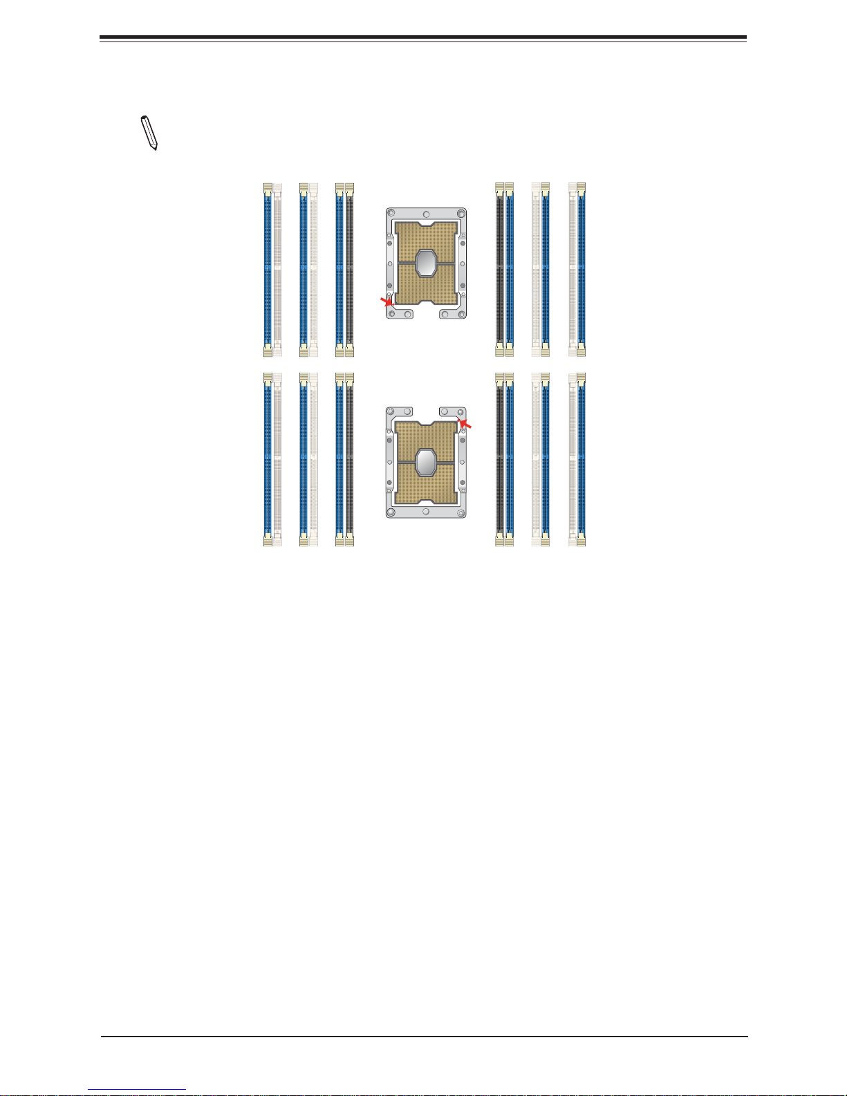
Note: Please refer to the memory population table on the previous page for memory
population.
CPU2
P2-DIMMC1
P2-DIMMB1
P1-DIMME1
P1-DIMMF1
P2-DIMMA2
P2-DIMMA1
Pin 1
P1-DIMMD2
P1-DIMMD1
CPU1
P2-DIMMD2
Pin 1
P1-DIMMA2
P2-DIMMD1
P2-DIMME1
P1-DIMMA1
P1-DIMMB1
P2-DIMMF1
P1-DIMMC1
11
Page 12
Supermicro Memory Confi guration User Guide for the X11 Series Motherboards
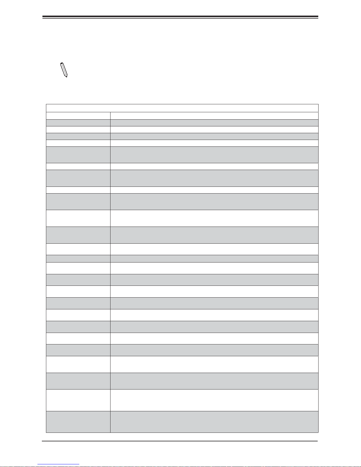
5.4.4 Memory Population for the X11DP Motherboards with 24 DIMM Slots
Onboard
Notes 1. Unbalanced memory confi guration decreases memory performance and is
not recommended for Supermicro motherboards. 2. The memory table below supports
the X11DP motherboards with 24 DIMM memory slots, such as X11DPU, X11DPT-B,
X11DPU-Z+, X11DSC+, X11PDT-BH, X11DSF, X11DPG-OT-CPU, X11DPS-R.
Memory Population Table for the X11DP Motherboard w/24 DIMM Slots Onboard
When 1 CPU is used: Memory Population Sequence
1 CPU & 1 DIMM CPU1: P1-DIMMA1
1 CPU & 2 DIMMs CPU1: P1-DIMMA1/P1-DIMMD1
1 CPU & 3 DIMMs CPU1: P1-DIMMC1/P1-DIMMB1/P1-DIMMA1
1 CPU & 4 DIMMs CPU1: P1-DIMMB1/P1-DIMMA1/P1-DIMMD1/P1-DIMME1
1 CPU & 5 DIMMs
(Unbalanced: not recom-
mended)
1 CPU & 6 DIMM CPU1: P1-DIMMC1/P1-DIMMB1/P1-DIMMA1/P1-DIMMD1/P1-DIMME1/P1-DIMMF1
1 CPU & 7 DIMMs
(Unbalanced: not recom-
mended)
1 CPU & 8 DIMMs CPU1: P1-DIMMB1/P1-DIMMB2/P1-DIMMA1/P1-DIMMA2/P1-DIMMD2/P1-DIMMD1/P1-DIMME2/P1-DIMME1
1 CPU & 9 DIMMs
(Unbalanced: not recom-
mended)
1 CPU & 10 DIMMs
(Unbalanced: not recom-
mended)
1 CPU & 11 DIMMs
(Unbalanced: not recom-
mended)
1 CPU & 12 DIMMs
When 2 CPUs are used: Memory Population Sequence
2 CPUs & 2 DIMMs
2 CPUs & 4 DIMMs
2 CPUs & 6 DIMMs
2 CPUs & 8 DIMMs
2 CPUs & 10 DIMMs
2 CPUs & 12 DIMMs
2 CPUs & 14 DIMMs
2 CPUs & 16 DIMMs
2 CPUs & 18 DIMMs
2 CPUs & 20 DIMMs
2 CPUs & 22 DIMMs
(Unbalanced: not recom-
mended)
2 CPUs & 24 DIMMs
CPU1: P1-DIMMC1/P1-DIMMB1/P1-DIMMA1/P1-DIMMD1/P1-DIMME1
CPU1: P1-DIMMB1/P1-DIMMB2/P1-DIMMA1/P1-DIMMA2/P1-DIMMD1/P1-DIMME1/P1-DIMMF1
CPU1: P1-DIMMC1/P1-DIMMC2/P1-DIMMB1/P1-DIMMB2/P1-DIMMA1/P1-DIMMA2/
P1-DIMMD1/P1-DIMME1/P1-DIMMF1
CPU1: P1-DIMMC1/P1-DIMMB1/P1-DIMMB2/P1-DIMMA1/P1-DIMMA2/
P1-DIMMD2/P1-DIMMD1/P1-DIMME2/P1-DIMME1/P1-DIMMF1
CPU1: P1-DIMMC1/P1-DIMMC2/P1-DIMMB1/P1-DIMMB2/P1-DIMMA1/P1-DIMMA2/
P1-DIMMD2/P1-DIMMD1/P1-DIMME2/P1-DIMME1/P1-DIMMF1
CPU1: P1-DIMMC1/P1-DIMMC2/P1-DIMMB1/P1-DIMMB2/P1-DIMMA1/P1-DIMMA2/
P1-DIMMD2/P1-DIMMD1/P1-DIMME2/P1-DIMME1/P1-DIMMF2/P1-DIMMF1
CPU1: P1-DIMMA1
CPU2: P2-DIMMA1
CPU1: P1-DIMMA1/P1-DIMMD1
CPU2: P2-DIMMA1/P2-DIMMD1
CPU1: P1-DIMMC1/P1-DIMMB1/P1-DIMMA1
CPU2: P2-DIMMC1/P2-DIMMB1/P2-DIMMA1
CPU1: P1-DIMMB1/P1-DIMMA1/P1-DIMMD1/P1-DIMME1
CPU2: P2-DIMMB1/P2-DIMMA1/P2-DIMMD1/P2-DIMME1
CPU1: P1-DIMMC1/P1-DIMMB1/P1-DIMMA1/P1-DIMMD1/P1-DIMME1/P1-DIMMF1
CPU2: P2-DIMMB1/P2-DIMMA1/P2-DIMMD1/P2-DIMME1
CPU1: P1-DIMMC1/P1-DIMMB1/P1-DIMMA1/P1-DIMMD1/P1-DIMME1/P1-DIMMF1
CPU2: P2-DIMMC1/P2-DIMMB1/P2-DIMMA1/P2-DIMMD1/P2-DIMME1/P2-DIMMF1
CPU1: P1-DIMMB1/P1-DIMMB2/P1-DIMMA1/P1-DIMMA2/P1-DIMMD2/P1-DIMMD1/P1-DIMME2/P1-DIMME1
CPU2: P2-DIMMC1/P2-DIMMB1/P2-DIMMA1/P2-DIMMD1/P2-DIMME1/P2-DIMMF1
CPU1: P1-DIMMB1/P1-DIMMB2/P1-DIMMA1/P1-DIMMA2/P1-DIMMD2/P1-DIMMD1/P1-DIMME2/P1-DIMME1
CPU2: P2-DIMMB1/P2-DIMMB2/P2-DIMMA1/P2-DIMMA2/P2-DIMMD2/P2-DIMMD1/P2-DIMME2/P2-DIMME1
CPU1: P1-DIMMC1/P1-DIMMC2/P1-DIMMB1/P1-DIMMB2/P1-DIMMA1/P1-DIMMA2/P1-DIMMD2/P1-DIMMD1/
P1-DIMME2/P1-DIMME1/P1-DIMMF2/P1-DIMMF1
CPU2: P2-DIMMC1/P2-DIMMB1/P2-DIMMA1/P2-DIMMD1/P2-DIMME1/P2-DIMMF1
CPU1: P1-DIMMC1/P1-DIMMC2/P1-DIMMB1/P1-DIMMB2/P1-DIMMA1/P1-DIMMA2/P1-DIMMD2/P1-DIMMD1/
P1-DIMME2/P1-DIMME1/P1-DIMMF2/P1-DIMMF1
CPU2: P2-DIMMB1/P2-DIMMB2/P2-DIMMA1/P2-DIMMA2/P2-DIMMD2/P2-DIMMD1/P2-DIMME2/P2-DIMME1
CPU1: P1-DIMMC1/P1-DIMMC2/P1-DIMMB1/P1-DIMMB2/P1-DIMMA1/P1-DIMMA2/
P1-DIMMD2/P1-DIMMD1/P1-DIMME2/P1-DIMME1/P1-DIMMF1
CPU2: P2-DIMMC1/P2-DIMMC2/P2-DIMMB1/P2-DIMMB2/P2-DIMMA1/P2-DIMMA2/
P2-DIMMD2/P2-DIMMD1/P2-DIMME2/P2-DIMME1/P2-DIMMF1
CPU1: P1-DIMMC1/P1-DIMMC2/P1-DIMMB1/P1-DIMMB2/P1-DIMMA1/P1-DIMMA2/
P1-DIMMD2/P1-DIMMD1/P1-DIMME2/P1-DIMME1/P1-DIMMF2/P1-DIMMF1
CPU2: P2-DIMMC1/P2-DIMMC2/P2-DIMMB1/P2-DIMMB2/P2-DIMMA1/P2-DIMMA2/
P2-DIMMD2/P2-DIMMD1/P2-DIMME2/P2-DIMME1/P2-DIMMF2/P2-DIMMF1
12
Page 13
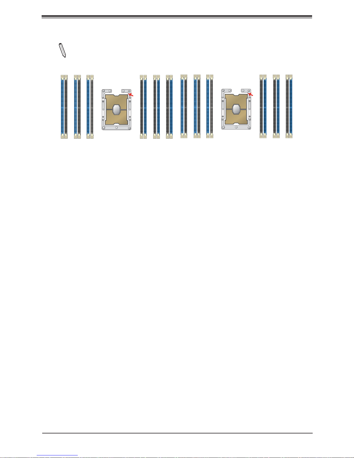
DIMM Population Guidelines
Note: Please refer to the memory population table on the previous page for memory
population.
P2-DIMMA1
P2-DIMMB1
P2-DIMMC1
P1-DIMMA1
P1-DIMMC1
P1-DIMMB1
P2-DIMMF1
P2-DIMME1
P2-DIMMF2
P2-DIMME2
P2-DIMMD1
P2-DIMMD2
CPU2
Pin 1
P2-DIMMA2
P2-DIMMB2
P2-DIMMC2
P1-DIMMF1
P1-DIMME1
P1-DIMMF2
P1-DIMMD1
P1-DIMMD2
P1-DIMME2
CPU1
Pin 1
P1-DIMMA2
P1-DIMMB2
P1-DIMMC2
13
Page 14
Supermicro Memory Confi guration User Guide for the X11 Series Motherboards
5.5 Memory Population Tables for the X11MP Motherboards
For your system memory to work properly, please follow the memory population tables
below to install your memory modules on the X11MP (4-way/8-way) motherboards.
These memory population tables were created based on the general memory population guidelines provided by Intel to support Supermicro's X11 Series motherboards.
5.5.1 Memory Population for the 4-way Motherboard w/Half Memory
Confi guration Support (X11QPH+ with 24 DIMM Slots Installed)
Note 1: Unbalanced memory confi guration decreases memory performance and is not
recommended for Supermicro motherboards.
Note 2: The following memory population table supports Supermicro's X11MP 4-way
motherboards, such as X11QPH+.
Memory Population Table for the 4-way Motherboard w/Half Memory Confi guration Support
(X11QPH+ w/4 CPUs & 24 DIMMs Installed)
4 CPUs & 24 DIMMs
(6 DIMMs per CPU)
CPU1 + 6 DIMMs CPU1: P1-DIMMC1/P1-DIMMB1/P1-DIMMA1/P1-DIMMD1/P1-DIMME1/P1-DIMMF1
CPU2 + 6 DIMMs CPU2: P2-DIMMC1/P2-DIMMB1/P2-DIMMA1/P2-DIMMD1/P2-DIMME1/P2-DIMMF1
CPU3 + 6 DIMMs CPU3: P3-DIMMC1/P3-DIMMB1/P3-DIMMA1/P3-DIMMD1/P3-DIMME1/P3-DIMMF1
CPU4 + 6 DIMMs CPU4: P4-DIMMC1/P4-DIMMB1/P4-DIMMA1/P4-DIMMD1/P4-DIMME1/P4-DIMMF1
Memory Population Sequence
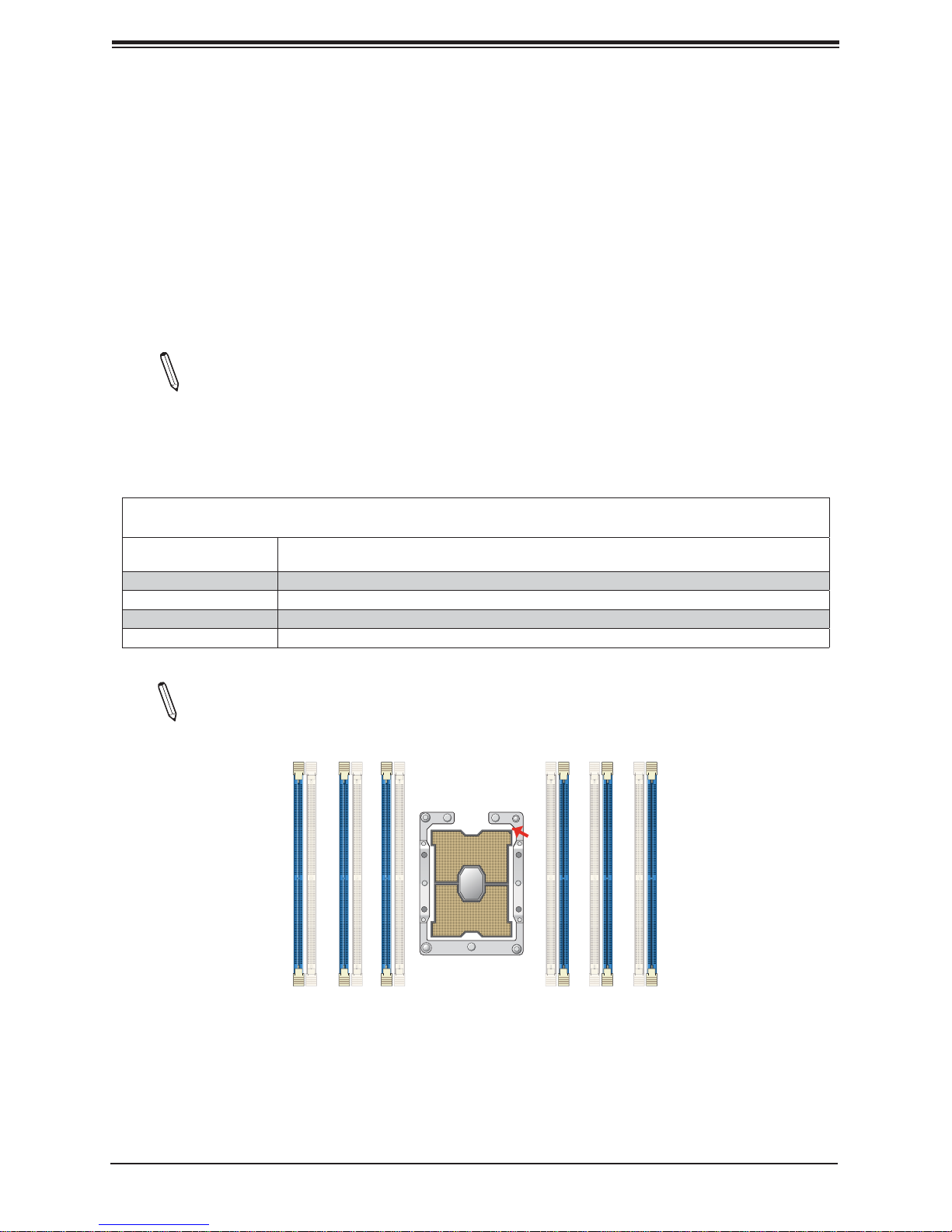
Note: The diagram below shows DIMM module population for each CPU installed on
the motherboard. Please install your processors starting with CPU Socket 1.
DIMME1
DIMMF1
DIMMD1
DIMMA1
Pin 1
DIMMC1
DIMMB1
14
Page 15
DIMM Population Guidelines
5.5.2 Memory Population for the 4-way Motherboard w/Full Memory
Confi guration Support (X11QPH+ with 48 DIMM Slots Installed)
Note 1: Unbalanced memory confi guration decreases memory performance and is not
recommended for Supermicro motherboards.
Note 2: The following memory population table supports Supermicro's X11MP 4-way
motherboards, such as X11QPH+.
Memory Population Table for the 4-way Motherboard w/Full Memory Confi guration Support
(X11QPH+ w/4 CPUs & 48 DIMMs Installed)
4 CPUs & 48 DIMMs
(12 DIMMs per CPU
board)
CPU1 + 12 DIMMs
CPU2 + 12 DIMMs
CPU3 + 12 DIMMs
CPU4 + 12 DIMMs
Memory Population Sequence
CPU1:
P1-DIMMC1/P1-DIMMC2/P1-DIMMB1/P1-DIMMB2/P1-DIMMA1/P1-DIMMA2/
P1-DIMMD2/P1-DIMMD1/P1-DIMME2/P1-DIMME1/P1-DIMMF2/P1-DIMMF1
CPU2:
P2-DIMMC1/P2-DIMMC2/P2-DIMMB1/P2-DIMMB2/P2-DIMMA1/P2-DIMMA2/
P2-DIMMD2/P2-DIMMD1/P2-DIMME2/P2-DIMME1/P2-DIMMF2/P2-DIMMF1
CPU3:
P3-DIMMC1/P3-DIMMC2/P3-DIMMB1/P3-DIMMB2/P3-DIMMA1/P3-DIMMA2/
P3-DIMMD2/P3-DIMMD1/P3-DIMME2/P3-DIMME1/P3-DIMMF2/P3-DIMMF1
CPU4:
P4-DIMMC1/P4-DIMMC2/P4-DIMMB1/P4-DIMMB2/P4-DIMMA1/P4-DIMMA2/
P4-DIMMD2/P4-DIMMD1/P4-DIMME2/P4-DIMME1/P4-DIMMF2/P4-DIMMF1
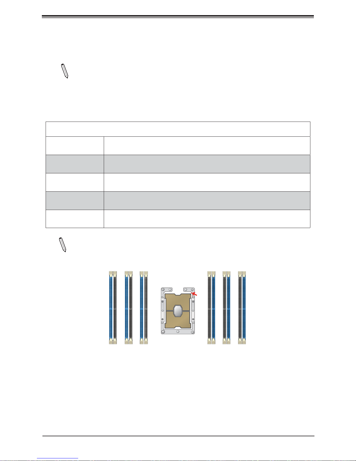
Note: The diagram below shows DIMM module population for each CPU installed on
the motherboard. Please install your processors starting with CPU Socket 1.
DIMMC1
DIMMB1
DIMMC2
DIMMF1
DIMMF2
DIMMD1
DIMME1
DIMME2
DIMMD2
Pin 1
DIMMA1
DIMMB2
DIMMA2
15
Page 16
Supermicro Memory Confi guration User Guide for the X11 Series Motherboards
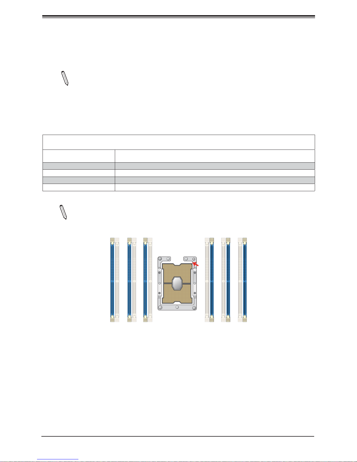
5.5.3 Memory Population for the 8-way Motherboard w/Half CPU & Half
Memory Confi guration Support (X11OPi+ w/4 CPU Boards & 24 DIMM Slots
Installed)
Note 1: Unbalanced memory confi guration decreases memory performance and is not
recommended for Supermicro motherboards.
Note 2: The following memory population table supports Supermicro's X11MP 8-way
motherboards, such as X11OPi+.
Memory Population Table for the 8-way Motherboard w/Half CPU & Half Memory Confi guration
Support (X11OPi+ w/4 CPUs & 24 DIMMs Installed)
4 CPUs & 24 DIMMs
(6 DIMMs per CPU board)
CPU Board 1 + 6 DIMMs CPU1: P1-DIMMC1/P1-DIMMB1/P1-DIMMA1/P1-DIMMD1/P1-DIMME1/P1-DIMMF1
CPU Board 2 + 6 DIMMs CPU2: P2-DIMMC1/P2-DIMMB1/P2-DIMMA1/P2-DIMMD1/P2-DIMME1/P2-DIMMF1
CPU Board 3 + 6 DIMMs CPU3: P3-DIMMC1/P3-DIMMB1/P3-DIMMA1/P3-DIMMD1/P3-DIMME1/P3-DIMMF1
CPU Board 4 + 6 DIMMs CPU4: P4-DIMMC1/P4-DIMMB1/P4-DIMMA1/P4-DIMMD1/P4-DIMME1/P4-DIMMF1
Memory Population Sequence
Note: The diagram below shows DIMM module population for each CPU Board in-
stalled in your system. Please install your processors starting with CPU Board #1.
DIMME1
DIMMF1
DIMMD1
DIMMA1
Pin 1
DIMMC1
DIMMB1
16
Page 17
DIMM Population Guidelines
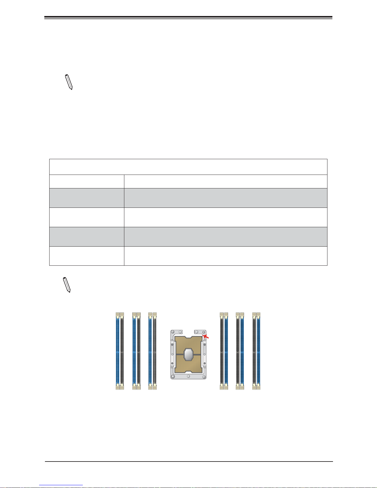
5.5.4 Memory Population for the 8-way Motherboard w/Half CPU & Full
Memory Confi guration Support (X11OPi+ w/4 CPU Boards & 48 DIMM Slots
Installed)
Note 1: Unbalanced memory confi guration decreases memory performance and is not
recommended for Supermicro motherboards.
Note 2: The following memory population table supports Supermicro's X11MP 8-way
motherboards, such as X11OPi+.
Memory Population Table for the 8-way Motherboard w/Half CPU & Full Memory Confi gura-
tion Support (X11OPi+ w/4 CPU Boards & 48 DIMMs Installed)
4 CPU boards & 48 DIMMs
(12 DIMMs per CPU board)
CPU Board 1 + 12 DIMMs
CPU Board 2 + 12 DIMMs
CPU Board 3 + 12 DIMMs
CPU Board 4 + 12 DIMMs
Memory Population Sequence
CPU1:
P1-DIMMC1/P1-DIMMC2/P1-DIMMB1/P1-DIMMB2/P1-DIMMA1/P1-DIMMA2/
P1-DIMMD2/P1-DIMMD1/P1-DIMME2/P1-DIMME1/P1-DIMMF2/P1-DIMMF1
CPU2:
P2-DIMMC1/P2-DIMMC2/P2-DIMMB1/P2-DIMMB2/P2-DIMMA1/P2-DIMMA2/
P2-DIMMD2/P2-DIMMD1/P2-DIMME2/P2-DIMME1/P2-DIMMF2/P2-DIMMF1
CPU3:
P3-DIMMC1/P3-DIMMC2/P3-DIMMB1/P3-DIMMB2/P3-DIMMA1/P3-DIMMA2/
P3-DIMMD2/P3-DIMMD1/P3-DIMME2/P3-DIMME1/P3-DIMMF2/P3-DIMMF1
CPU4:
P4-DIMMC1/P4-DIMMC2/P4-DIMMB1/P4-DIMMB2/P4-DIMMA1/P4-DIMMA2/
P4-DIMMD2/P4-DIMMD1/P4-DIMME2/P4-DIMME1/P4-DIMMF2/P4-DIMMF1
Note: The diagram below shows DIMM module population for each CPU Board installed in your system. Please install your processors starting with CPU Board #1.
DIMMC1
DIMMB1
DIMMC2
DIMMF1
DIMMF2
DIMMD1
DIMME1
DIMME2
DIMMD2
Pin 1
DIMMA1
DIMMB2
DIMMA2
17
Page 18
Supermicro Memory Confi guration User Guide for the X11 Series Motherboards
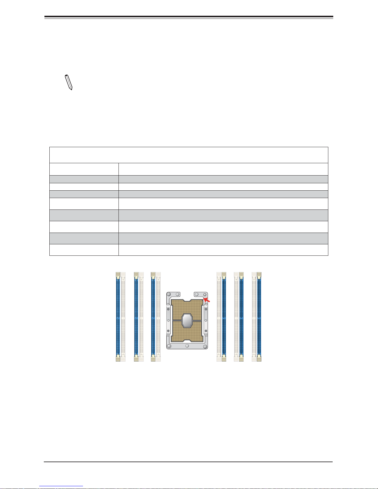
5.5.5 Memory Population for the 8-way Motherboard w/Full CPU &Half
Memory Confi guration Support (X11OPi+ w/8 CPU Boards & 48 DIMM Slots
Installed)
Note 1: Unbalanced memory confi guration decreases memory performance and is not
recommended for Supermicro motherboards.
Note 2: The following memory population table supports Supermicro's X11MP 8-way
motherboards, such as X11OPi+.
Memory Population Table for the 8-way Motherboard w/Full CPU & Half Memory Confi guration
Support (X11OPi+ w/8 CPU Boards & 48 DIMMs Installed)
8 CPU boards & 48 DIMMs
(6 DIMMs per CPU board)
CPU Board 1 + 6 DIMMs CPU1: P1-DIMMC1/P1-DIMMB1/P1-DIMMA1/P1-DIMMD1/P1-DIMME1/P1-DIMMF1
CPU Board 2 + 6 DIMMs CPU2: P2-DIMMC1/P2-DIMMB1/P2-DIMMA1/P2-DIMMD1/P2-DIMME1/P2-DIMMF1
CPU Board 3 + 6 DIMMs CPU3: P3-DIMMC1/P3-DIMMB1/P3-DIMMA1/P3-DIMMD1/P3-DIMME1/P3-DIMMF1
CPU Board 4 + 6 DIMMs CPU4: P4-DIMMC1/P4-DIMMB1/P4-DIMMA1/P4-DIMMD1/P4-DIMME1/P4-DIMMF1
Memory Population Sequence
CPU Board 5 + 6 DIMMs CPU5: P5-DIMMC1/P5-DIMMB1/P5-DIMMA1/P5-DIMMD1/P5-DIMME1/P5-DIMMF1
CPU Board 6 + 6 DIMMs CPU6: P6-DIMMC1/P6-DIMMB1/P6-DIMMA1/P6-DIMMD1/P6-DIMME1/P6-DIMMF1
CPU Board 7 + 6 DIMMs CPU7: P7-DIMMC1/P7-DIMMB1/P7-DIMMA1/P7-DIMMD1/P7-DIMME1/P7-DIMMF1
CPU Board 8 + 6 DIMMs CPU8: P4-DIMMC1/P8-DIMMB1/P8-DIMMA1/P8-DIMMD1/P8-DIMME1/P8-DIMMF1
DIMME1
DIMMF1
DIMMD1
DIMMA1
Pin 1
DIMMC1
DIMMB1
18
Page 19
DIMM Population Guidelines
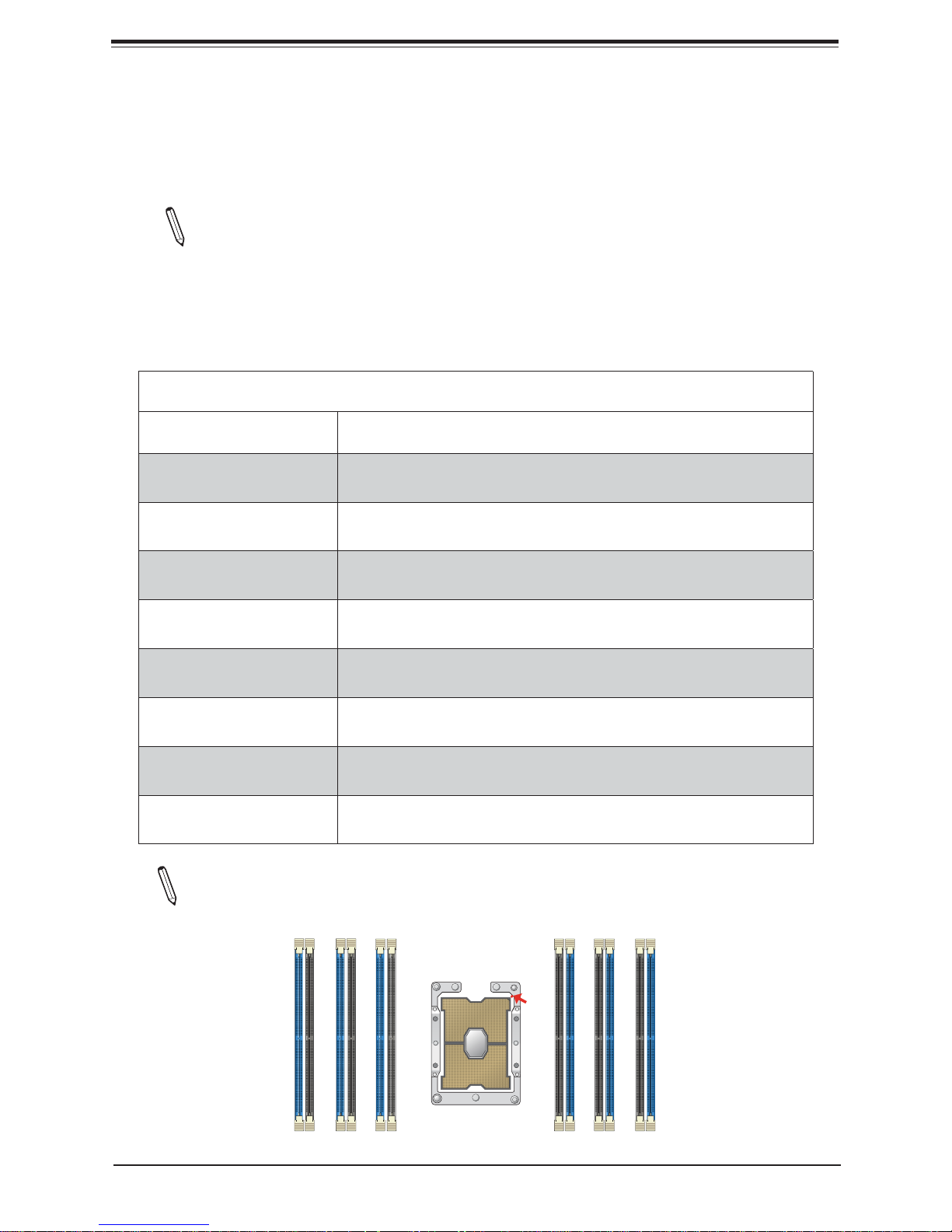
5.5.6 Memory Population for the 8-way Motherboard w/Full CPU &Memory
Confi guration Support (X11OPi+ w/8 CPU Boards & 96 DIMM Slots
Installed)
Note 1: Unbalanced memory confi guration decreases memory performance and is
not recommended for Supermicro motherboards. To maximize memory capacity and
performance, please populate DIMM modules to
Note 2: The following memory population table supports Supermicro's X11MP 8-way
motherboards, such as X11OPi+.
Memory Population Table for the 8-way Motherboard w/Full CPU & Memory
Confi guration Support (X11OPi+ w/8 CPU Boards & 96 DIMMs Installed)
8 CPU boards & 96 DIMMs
(12 DIMMs per CPU board)
CPU Board 1 + 12 DIMMs
CPU Board 2 + 12 DIMMs
CPU Board 3 + 12 DIMMs
CPU Board 4 + 12 DIMMs
CPU Board 5 + 12 DIMMs
CPU Board 6 + 12 DIMMs
CPU Board 7 + 12 DIMMs
CPU Board 8 + 12 DIMMs
Memory Population Sequence
CPU1:
P1-DIMMC1/P1-DIMMC2/P1-DIMMB1/P1-DIMMB2/P1-DIMMA1/P1-DIMMA2/
P1-DIMMD2/P1-DIMMD1/P1-DIMME2/P1-DIMME1/P1-DIMMF2/P1-DIMMF1
CPU2:
P2-DIMMC1/P2-DIMMC2/P2-DIMMB1/P2-DIMMB2/P2-DIMMA1/P2-DIMMA2/
P2-DIMMD2/P2-DIMMD1/P2-DIMME2/P2-DIMME1/P2-DIMMF2/P2-DIMMF1
CPU3:
P3-DIMMC1/P3-DIMMC2/P3-DIMMB1/P3-DIMMB2/P3-DIMMA1/P3-DIMMA2/
P3-DIMMD2/P3-DIMMD1/P3-DIMME2/P3-DIMME1/P3-DIMMF2/P3-DIMMF1
CPU4:
P4-DIMMC1/P4-DIMMC2/P4-DIMMB1/P4-DIMMB2/P4-DIMMA1/P4-DIMMA2/
P4-DIMMD2/P4-DIMMD1/P4-DIMME2/P4-DIMME1/P4-DIMMF2/P4-DIMMF1
CPU5:
P5-DIMMC1/P5-DIMMC2/P5-DIMMB1/P5-DIMMB2/P5-DIMMA1/P5-DIMMA2/
P5-DIMMD2/P5-DIMMD1/P5-DIMME2/P5-DIMME1/P5-DIMMF2/P5-DIMMF1
CPU6:
P6-DIMMC1/P6-DIMMC2/P6-DIMMB1/P6-DIMMB2/P6-DIMMA1/P6-DIMMA2/
P6-DIMMD2/P6-DIMMD1/P6-DIMME2/P6-DIMME1/P6-DIMMF2/P6-DIMMF1
CPU7:
P7-DIMMC1/P7-DIMMC2/P7-DIMMB1/P7-DIMMB2/P7-DIMMA1/P7-DIMMA2/
P7-DIMMD2/P7-DIMMD1/P7-DIMME2/P7-DIMME1/P7-DIMMF2/P7-DIMMF1
CPU8:
P8-DIMMC1/P8-DIMMC2/P8-DIMMB1/P8-DIMMB2/P8-DIMMA1/P8-DIMMA2/
P8-DIMMD2/P8-DIMMD1/P8-DIMME2/P8-DIMME1/P8-DIMMF2/P8-DIMMF1
Note: The diagram below shows DIMM module population for each CPU Board installed in your system. Please install your processors starting with CPU Board #1.
DIMMF1
DIMMF2
DIMMD1
DIMME1
DIMME2
DIMMD2
19
Pin 1
DIMMA1
DIMMB2
DIMMA2
DIMMB1
DIMMC2
DIMMC1
Page 20
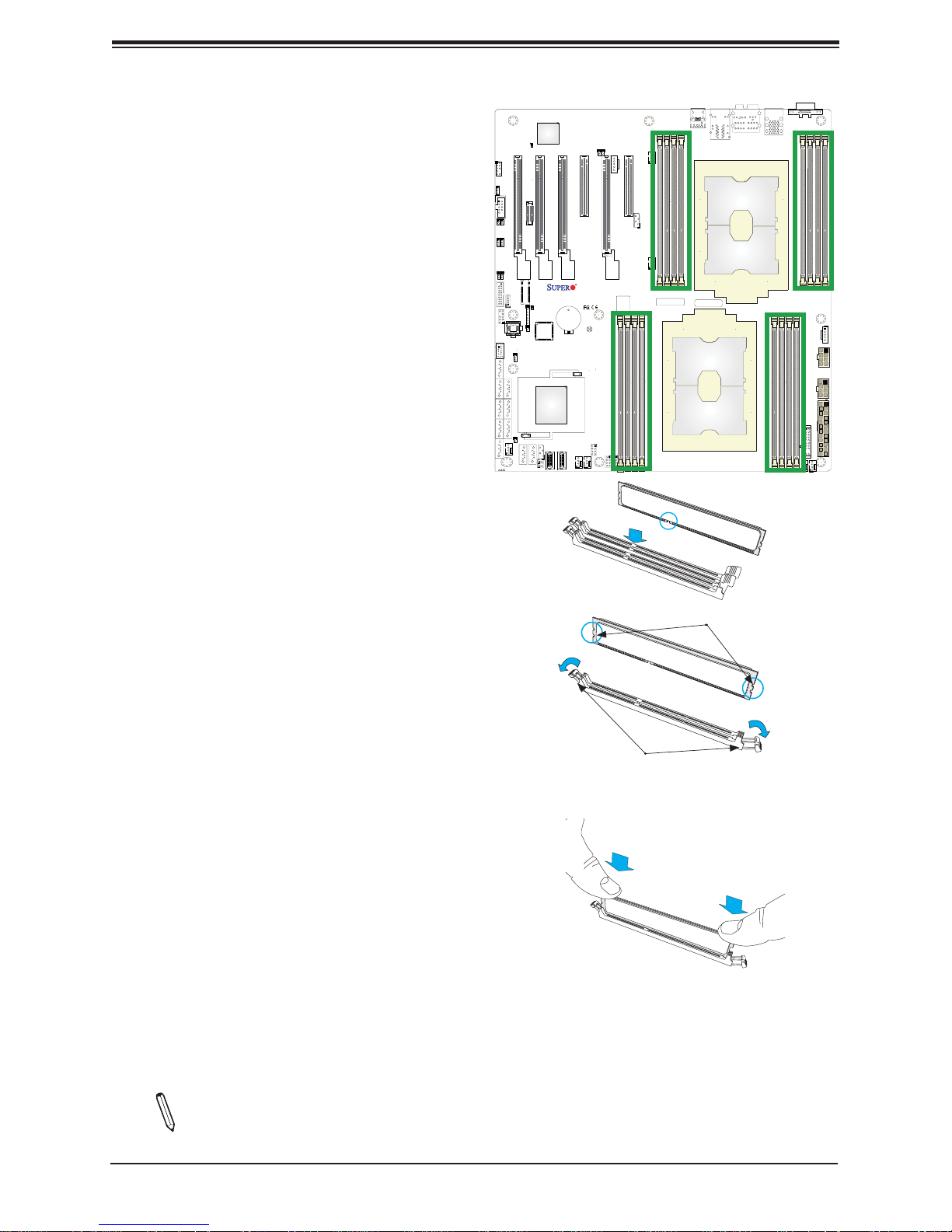
6 DIMM Installation
1. Follow the instructions given in the
memory population guidelines listed in
the previous sections to install memory
modules on your motherboard. For the
system to work properly, please use
memory modules of the same type and
speed on the motherboard. (See the Note
below.)
2. Push the release tabs outwards on both
ends of the DIMM slot to unlock it.
3. Align the key of the DIMM module with the
receptive point on the memory slot.
DIMM Population Guidelines
X11DAi-N
REV:1.01
LICENSE
BIOS
BAR CODE
MAC CODE
4. Align the notches on both ends of the
module against the receptive points on the
ends of the slot.
5. Use two thumbs together to press the
DIMM module straight down into the slot
until the module snaps into place.
6. Press the release tabs to the lock positions
to secure the DIMM module into the slot.
7 DIMM Removal
Reverse the steps above to remove the DIMM
modules from the motherboard.
Notches
Release Tabs
Insert the DIMM module into the memory slot.
Note: All graphics including the layout drawing above are for reference only. Your sys-
tem components may look or may not look the same as graphics shown in this guide.
20
 Loading...