

Page 1
S
UPERMICR
R
CONTACT INFORMATION
• Manuals: http://www.supermicro.com/support/manuals
• Drivers & Utilities: ftp://ftp.supermicro.com/CDR_Images/CDR-X11-UP/
• Safety: http://www.supermicro.com/about/policies/safety_information.cfm
© 2014 Supermicro Computer Inc. All rights reserved. Reproduction of this document whether in part or in whole is strictly prohibited without Supermicro's written
consent. All Trademarks are property of their respective entities. All information provided is deemed accurate at the time of printing; however, it is not guaranteed.
PACKAGE CONTENTS
X11SSL-CF_(-NF)
QUICK REFERENCE GUIDE 1.00
• One (1) Supermicro Motherboard
• Six (6) SATA Cables
• One (1) I/O Shield
• One (1) Quick Reference Guide
• Website: www.supermicro.com
• General Information: [email protected]
• Technical Support: [email protected]
• Phone: +1 (408) 503-8000, Fax: +1 (408) 503-8008
FOR YOUR SYSTEM TO WORK PROPERLY, PLEASE DOWNLOAD APPROPRIATE
DRIVERS/IMAGES/USER'S MANUAL FROM THE LINKS BELOW:
MNL-1782-QRG REV. 1.00
LED Item # Description Color/State Status
LE1 60 Rear UID LED Blue: On Unit Identifi ed
LEDBMC 61 BMC Heartbeat LED Green: Blinking BMC Normal
LEDPWR 62 System Power LED Green: Solid on Power On
LEDS1 63 SAS LED
Green Blinking SAS Active
Red: Solid On SAS Error
Connectors
Jumpers and Connectors
Back Panel I/O Connectors
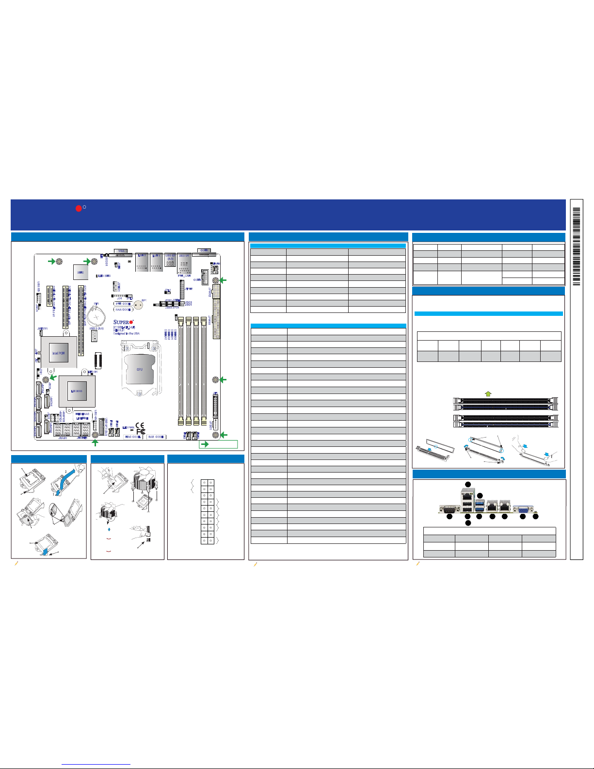
Motherboard Layout and Features
Jumpers
CPU Installation
Note: Graphics shown in this quick reference guide are for illustration only. Your components may or may not look exactly the same as drawings shown in this guide.
Note: Refer to Chapter 1 of the User Manual for detailed information on jumpers, connectors,
and LED indicators.
Note: Refer to Chapter 2 of the User Manual for detailed information on memory support and CPU/
motherboard installation instructions.
= mounting hole
Heatsink Installation
Front Panel Control (JF1)
LED Indicators
Jumper Description Default
JBR1 BIOS Recovery Pins 1-2 (Normal)
JBT1 Clear CMOS See Chapter 2
JI
2
C1/JI2C2 SMB to PCI Slots Pins 2-3 (Disabled)
JPB1 BMC Enable/Disable Pins 1-2 (Enabled)
JPG1 VGA Enable Pins 1-2 (Enabled)
JPL1/JPL2 LAN1/LAN2 Enable Pins 1-2 (Enabled)
JPME2 Manufacturing Mode Select Pins 1-2 (Normal)
JPS1 SAS Enable Pins 1-2 (Enabled)
JWD1 Watch Dog Enable Pins 1-2 (Reset)
Connector Description
BT1 Onboard Battery
COM1/COM2 COM1/COM2 Port Headers
Fan1-Fan4, FanA System/CPU Fan Headers
IPMI_LAN IPMI_Dedicated Gigabit (RJ45) Port
I-SATA0-I-SATA5
SATA 3.0 Connectors via Intel PCH (6Gb/s)
I-SGPIO 1/2 Serial_Link General Purpose I/O Connection Headers for I-SATA 3.0 connections
JD1 Speaker/Power LED Indicator
JF1 Front Panel Control Header
JIPMB1 4-pin External BMC I
2
C Header (for an IPMI Card)
JL1 Chassis Intrusion Header
JNVME1 Two (2) NVMe SSD Ports (X11SSL-nF Only)
JOH1 Overheat LED Indicator
JPI
2
C1 Power I2C System Management Bus (Power SMB) Header
JPWR1 24-pin ATX Main Power Connector (Required)
JPWR2 +12V 8-pin CPU Power Connector (Required)
JSAS1 Two (2) Mini-SAS HD Ports (X11SSL-CF Only)
JSD1/JSD2 SATA Disk On Module (DOM) Power Connectors
JSTBY1 Wake-On-LAN Enable Header
JTPM1 Trusted Platform Module/Port 80 Connector
JUIDB1 UID (Unit Identifi cation) Switch
LAN1/LAN2 Gigabit (RJ45) LAN Ports
PCI-E (PCH) Slot 4 PCI-Express 3.0 x1 Slot
PCI-E (PCH) Slot 5 PCI-Express 3.0 x4 in x8 Slot
PCI-E (CPU) Slot 6 PCI-Express 3.0 x8 in x16 Slot
SP1 Internal Speaker/Buzzer
USB 0/1 Back Pa nel U SB 2 .0 Por t s
USB 2/3 Front Accessible USB 2.0 Headers
USB 4/5 Front Accessible USB 2.0 Headers
USB 6/7 Back Panel USB 3.0 Ports
USB 8 USB 3.0 Type-A Header
USB 9/10 Fro nt Ac ce ssi ble U SB 3 .0 He ade r
VGA Back Panel VGA Port
A
B
C
E
G
H
I
J
Power Button
Blue+ (OH/Fan Fail)
1
NIC1 Link LED
Reset Button
2
Power Fail LED
HDD LED
FP PWRLED
Reset
PWR
3.3 V
ID_UID_SW/3.3V Stdby
Red+ (Blue LED Cathode)
Ground
Ground
19 20
3.3V
X
X
NIC2 Link LED
NIC2 Active LED
NIC1 Active LED
X
X
DIMM Memory Installation
Memory Support
I/O Back Panel
A. COM 1 D. IPMI LAN G. LAN1 J. UID Switch
B. USB Port 0 (2.0) E. USB Port 6 (3.0) H. LAN2
C. USB Port 1 (2.0) F. USB Port 7 (3.0) I. VGA
CPU Properly
Installed
Load Lever Locked
into Place
Load Lever
Load Plate
Pin 1
North Center Edge
F
D
Turn Clockwise
to Lock
Thermal Paste
P
ush Down
Turn Counterclockwise to
Unlock
Connect the Heatsink Wire to
the CPU Fan Connector
The X11SSL-CF_(-nF) has four (4) 288-pin DIMM slots that support up to 64GB of
SDRAM 72-bit DDR4 unbuffered ECC 2133/1866/1600/1333MHz memory.
Memory Population Guidelines
Please follow the table below when populating the X11SSL-CF_(-nF):
Insert the desired number of DIMMs into the memory slots. The DIMM slots
should be populated in the following order: DIMMB2, DIMMA2, DIMMB1,
DIMMA1. For the system to work properly, please use memory modules of the
same type and speed in the motherboard.
Channel A Slot 1
Channel A Slot 2
(Blue Slot)
Channel B Slot 1
Channel B Slot 2
(Blue Slot)
Towards the CPU
Notches
Release Tabs
Press both notches
straight down into
the memory slot.
Memory Module Population
DIMM Slots
per Channel
DIMM Type
POR Speeds
(MHz)
Ranks per
DIMM
Layer
Count
FW Base
Supported
Voltage
2
Unbuffered
DDR4 ECC
2133, 1866,
1600, 1333
SR, DR 6 SPS 1.2V
1
JPWR2
JPWR1
BMC
Intel PCH
IPMI_LAN
USB 0/1
FAN4
JPWR2
USB 6/7
(3.0)
LAN 1
LAN 2
VGA
JTPM1
JPL1
JPL2JD1
LED BMC
JIPMB1
JOH1
LE1
JUIDB1
USB 8 (3.0)
LED S1
LEDPWR
FAN3
FANA
USB 4/5
USB 9/10 (3.0)
JSD1
I-SGPIO2
I-SGPIO1
JSD2
JL1
JBT1
JSTBY1
JPS1
X11SSL-CF_(-nF)
REV:1.01
Designed in the USA
MAC CODE SAS CODE
SP1
JPG1
JBR1
JPME2
JPB1
JI2C2
JI2C1
JF1
JPI2C1
FAN1
FAN2
BAR CODE
IPMI CODE
USB 2/3
PCH SLOT4 PCI-E 3.0 x1
PCH SLOT5 PCI-E 3.0 x4(in x8)
CPU SLOT6 PCI-E 3.0 x8(in x16)
I-SATA5
I-SATA1
I-SATA4
I-SATA3
I-SATA2
I-SATA0
JWD1
DIMMB2
DIMMB1
DIMMA2
DIMMA1
JSAS1
JNVME1
LSI 3008
CPU
BT1
MEGERAC
LICENSE
COM1
COM2
 Loading...