

Supermicro SuperServer 6013P-T, X5DPR-TG2 Plus Hardware Specifications
SuperServer 6013P-T Serverboard Components
6
0
59
5
0
58
57
52
56
55
54
53
51
X5DPR-TG2+ Quick Reference
JBT1 CMOS Clear Pad
JD1 Speaker Enable (Pins 6-7) Closed (Enabled)
JD4 Gigabit LAN En/disable Pins 1-2 (Enabled)
JP4 VGA En/disable Pins 1-2 (Enabled)
JP9 Power fail alarm En/disable Open (Disabled)
JP37 Watch dog En/disable Closed (Enabled)
JP38 Front side bus speed Pins 1-2 (Auto)
JPS1, JPS2 SATA 1/2 En/Disable Pins 1-2 (Enabled)
1 X5DPR-TG2+ Serverboard
2 JD4: Gigabit LAN Enable/Disable
3 JP24: SMB header
4 JP35: Keylock header
5 IPMI 1.5 socket
6 Super I/0
7 WOL: Wake-on-LAN header
8 WOR: Wake-on-Ring header
9 USB2 port
10 JPS1: SATA 1 Enable/Disable
11 JPS2: SATA 2 Enable/Disable
12 JL1: Chassis intrusion
13 JP37: Watch dog En/Disable
14 PWR LED
15 Speaker
16 JD1: Speaker Enable (pins 6-7)
17 SATA LED
18 SATA 2 controller
19 SATA 1 controller
20 FPUSB0/1 ports
21 SATA #0 port
22 SATA #1 port
23 SATA #2 port
24 SATA #3 port
25 Chassis Fan 3
26 COM2
27 Floppy conn.
28 IDE#2 port
29 IDE#1 port
30 Overheat LED
31 CPU2 chassis fan
32 JF2: Front control panel connector
33 CPU1 chassis fan
34 JP36: Alarm reset switch
35 JP9: Power fail alarm En/Disable
36 JP8: Third power supply fail header
37 ATX power conn.
38 J15: 12V power conn.
39 CPU1 socket
40 CPU2 socket
41 Bank 1
42 Bank 2
43 Bank 3
44 MCH chip
45 Keyboard
46 Mouse
47 USB 0/1
48 COM1
49 Gigabit LAN 1
50 Gigabit LAN 2
51 PCI#2
52 PCI-X #1
53 JP38: Front side bus speed
54 JBT1: CMOS clear
55 ICH3 chip
56 P64H2
57 Intel 82546EB chip
58 JP4: VGA Enable/Disable
59 VGA port
60 ATI Rage XL 8MB PCI controller
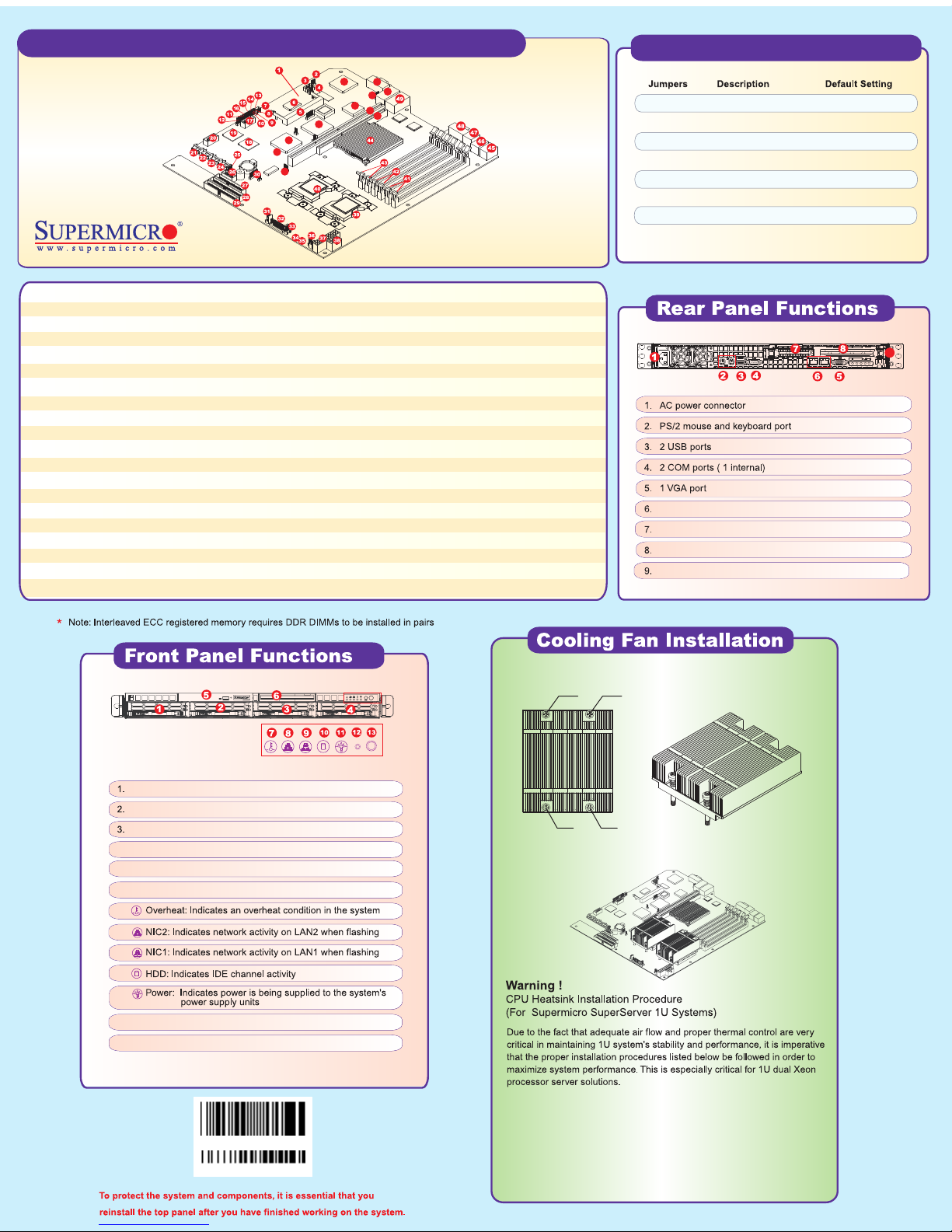
NO.1 SCREW
9
2 Gigabit LAN ports
1 Low-profile PCI-X/PCI expansion slot
1 Standard PCI-X/PCI expansion slot
PCI-X/PCI card release latch
NO.4 SCREW
Hot-plug SATA hard drive, ID 0
Hot-plug SATA hard drive, ID 1
Hot-plug SATA hard drive, ID 2
4. Hot-plug SATA hard drive, ID 3
5. 1 Slim CD-ROM drive
6. 1 Slim floppy drive
7.
8.
9.
10.
11.
12. Reset button
13. Power SW button
LBL-0099
REV 1.00
NO.3 SCREW NO.2 SCREW
Do not reuse thermal grease!!
1) Only those CPU heatsinks that are provided by Supermicro should be used.
2) Do not apply any thermal grease to the heatsink - the required amount has
already been applied.
3) Place the heatsink on top of the CPU so that the four mounting holes are
aligned with those on the chassis.
4) Screw in two diagonal screws (ie. the #1 and #2 screws) until just snug (do
not fully tighten), then do the same with the remaining two diagonal screws.
5) Finish by fully tightening all four screws.
 Loading...