

Supermicro SuperServer 5039MS-H12TRF User Manual
SuperServer
®
5039MS-H12TRF
USER’S MANUAL
Revision 1.0

SuperServer 5039MS-H12TRF User's Manual
The information in this User’s Manual has been carefully reviewed and is believed to be accurate. The vendor assumes
no responsibility for any inaccuracies that may be contained in this document, and makes no commitment to update
or to keep current the information in this manual, or to notify any person or organization of the updates. Please Note:
For the most up-to-date version of this manual, please see our website at www.supermicro.com.
Super Micro Computer, Inc. ("Supermicro") reserves the right to make changes to the product described in this manual
at any time and without notice. This product, including software and documentation, is the property of Supermicro and/
or its licensors, and is supplied only under a license. Any use or reproduction of this product is not allowed, except
as expressly permitted by the terms of said license.
IN NO EVENT WILL Super Micro Computer, Inc. BE LIABLE FOR DIRECT, INDIRECT, SPECIAL, INCIDENTAL,
SPECULATIVE OR CONSEQUENTIAL DAMAGES ARISING FROM THE USE OR INABILITY TO USE THIS PRODUCT
OR DOCUMENTATION, EVEN IF ADVISED OF THE POSSIBILITY OF SUCH DAMAGES. IN PARTICULAR, SUPER
MICRO COMPUTER, INC. SHALL NOT HAVE LIABILITY FOR ANY HARDWARE, SOFTWARE, OR DATA STORED
OR USED WITH THE PRODUCT, INCLUDING THE COSTS OF REPAIRING, REPLACING, INTEGRATING,
INSTALLING OR RECOVERING SUCH HARDWARE, SOFTWARE, OR DATA.
Any disputes arising between manufacturer and customer shall be governed by the laws of Santa Clara County in the
State of California, USA. The State of California, County of Santa Clara shall be the exclusive venue for the resolution
of any such disputes. Supermicro's total liability for all claims will not exceed the price paid for the hardware product.
FCC Statement: This equipment has been tested and found to comply with the limits for a Class A digital device
pursuant to Part 15 of the FCC Rules. These limits are designed to provide reasonable protection against harmful
interference when the equipment is operated in a commercial environment. This equipment generates, uses, and can
radiate radio frequency energy and, if not installed and used in accordance with the manufacturer’s instruction manual,
may cause harmful interference with radio communications. Operation of this equipment in a residential area is likely
to cause harmful interference, in which case you will be required to correct the interference at your own expense.
California Best Management Practices Regulations for Perchlorate Materials: This Perchlorate warning applies only
to products containing CR (Manganese Dioxide) Lithium coin cells. “Perchlorate Material-special handling may apply.
See www.dtsc.ca.gov/hazardouswaste/perchlorate”.
WARNING: Handling of lead solder materials used in this product may expose you to lead, a
chemical known to the State of California to cause birth defects and other reproductive harm.
The products sold by Supermicro are not intended for and will not be used in life support systems, medical equipment,
nuclear facilities or systems, aircraft, aircraft devices, aircraft/emergency communication devices or other critical
systems whose failure to perform be reasonably expected to result in signicant injury or loss of life or catastrophic
property damage. Accordingly, Supermicro disclaims any and all liability, and should buyer use or sell such products
for use in such ultra-hazardous applications, it does so entirely at its own risk. Furthermore, buyer agrees to fully
indemnify, defend and hold Supermicro harmless for and against any and all claims, demands, actions, litigation, and
proceedings of any kind arising out of or related to such ultra-hazardous use or sale.
Manual Revision 1.0
Release Date: March 10, 2016 mk
Unless you request and receive written permission from Super Micro Computer, Inc., you may not copy any part of this
document. Information in this document is subject to change without notice. Other products and companies referred
to herein are trademarks or registered trademarks of their respective companies or mark holders.
Copyright © 2016 by Super Micro Computer, Inc.
All rights reserved.
Printed in the United States of America
Preface
Preface
About this Manual
This manual is written for professional system integrators and PC technicians. It provides
information for the installation and use of the SuperServer Installation and maintainance
should be performed by experienced technicians only.
Please refer to the server specications page on our website for updates on supported
memory, processors and operating systems (http://www.supermicro.com).
Notes
For your system to work properly, please follow the links below to download all necessary
drivers/utilities and the user’s manual for your server.
• Supermicro product manuals: http://www.supermicro.com/support/manuals/
• Product drivers and utilities: ftp://ftp.supermicro.com
• Product safety info: http://www.supermicro.com/about/policies/safety_information.cfm
If you have any questions, please contact our support team at:
support@supermicro.com
This manual may be periodically updated without notice. Please check the Supermicro website
for possible updates to the manual revision level.
Warnings
Special attention should be given to the following symbols used in this manual.
Warning! Indicates important information given to prevent equipment/property damage
or personal injury.
Warning! Indicates high voltage may be encountered when performing a procedure.
3
3

SuperServer 5039MS-H12TRF User's Manual
Contents
Chapter 1 Introduction
1.1 Overview ...............................................................................................................................7
1.2 Unpacking the System .........................................................................................................7
1.3 System Features ..................................................................................................................8
1.4 Chassis Features .................................................................................................................9
Power Button/LED ...............................................................................................................9
Front Features ...................................................................................................................10
Rear Features ...................................................................................................................11
1.5 Motherboard Layout ...........................................................................................................12
Motherboard Jumpers, Connectors, and LEDs ................................................................13
Chapter 2 Installation in a Rack
2.1 Preparing for Setup ............................................................................................................15
Choosing a Setup Location ...............................................................................................15
Rack Precautions ..............................................................................................................15
Server Precautions ............................................................................................................16
Rack Mounting Considerations .........................................................................................16
2.2 Installing the Rails ............................................................................................................18
Chapter 3 Maintenance and Component Installation
3.1 Removing Power ................................................................................................................19
3.2 Accessing the System ........................................................................................................20
Top Cover ..........................................................................................................................20
Removing and Installing Motherboard Nodes ...................................................................21
Connecting to a Node .......................................................................................................22
3.3 Motherboard Components ..................................................................................................23
Processor and Heatsink Installation ..................................................................................23
Memory Installation ..........................................................................................................27
Memory Support ............................................................................................................27
DIMM Module Population Conguration ........................................................................27
DIMM Module Population Sequence .............................................................................28
Install Procedure ............................................................................................................29
Removal Procedure .......................................................................................................29
Expansion Module .............................................................................................................30
Motherboard Battery .........................................................................................................31
4

Preface
3.4 Chassis Components .........................................................................................................32
Hard Drives .......................................................................................................................32
System Cooling .................................................................................................................34
Corresponding Nodes and Fans ...................................................................................34
Replacing Fans ..............................................................................................................35
Air Shroud ......................................................................................................................36
Power Supply ...................................................................................................................37
Chapter 4 Motherboard Connections
4.1 Node Front Panel Controls.................................................................................................38
4.2 Headers and Connectors ....................................................................................................38
4.3 Ports ...................................................................................................................................40
4.4 Jumpers ..............................................................................................................................41
4.5 LED Indicators ....................................................................................................................43
Chapter 5 Software
5.1 OS Installation ..................................................................................................................44
Installing the Windows OS for a RAID System ................................................................44
Installing Windows to a Non-RAID System ......................................................................44
5.2 Driver Installation ................................................................................................................45
5.3 SuperDoctor® 5 ...................................................................................................................46
5.4 IPMI ....................................................................................................................................46
Chapter 6 BIOS
6.1 Introduction .........................................................................................................................47
Starting the Setup Utility ...................................................................................................47
6.2 Main Menu ..........................................................................................................................48
6.3 Advanced Setup Congurations .........................................................................................49
6.4 Event Logs .........................................................................................................................69
6.5 IPMI ....................................................................................................................................71
6.6 Security ...............................................................................................................................73
6.7 Boot ....................................................................................................................................76
6.8 Save & Exit .........................................................................................................................78
Appendix A BIOS Error Codes
Appendix B Standardized Warning Statements for AC Systems
Appendix C UEFI BIOS Recovery Instructions
Appendix D System Specications
5

SuperServer 5039MS-H12TRF User's Manual
SuperServer 5039MS-H12TRF User's Manual
Contacting Supermicro
Headquarters
Address: Super Micro Computer, Inc.
980 Rock Ave.
San Jose, CA 95131 U.S.A.
Tel: +1 (408) 503-8000
Fax: +1 (408) 503-8008
Email: marketing@supermicro.com (General Information)
support@supermicro.com (Technical Support)
Website: www.supermicro.com
Europe
Address: Super Micro Computer B.V.
Het Sterrenbeeld 28, 5215 ML
's-Hertogenbosch, The Netherlands
Tel: +31 (0) 73-6400390
Fax: +31 (0) 73-6416525
Email: sales@supermicro.nl (General Information)
support@supermicro.nl (Technical Support)
rma@supermicro.nl (Customer Support)
Website: www.supermicro.nl
Asia-Pacic
Address: Super Micro Computer, Inc.
3F, No. 150, Jian 1st Rd.
Zhonghe Dist., New Taipei City 235
Taiwan (R.O.C)
Tel: +886-(2) 8226-3990
Fax: +886-(2) 8226-3992
Email: support@supermicro.com.tw
Website: www.supermicro.com.tw
6
Chapter 1: Introduction
Chapter 1
Introduction
1.1 Overview
The SuperServer 5039MS-H12TRF is a MicroCloud server system in the SC939HS-R2K04BP
chassis, featuring twelve separate computing nodes each containing an X11SSE-F
motherboard.
In additon to the motherboards and chassis, several included parts are listed below.
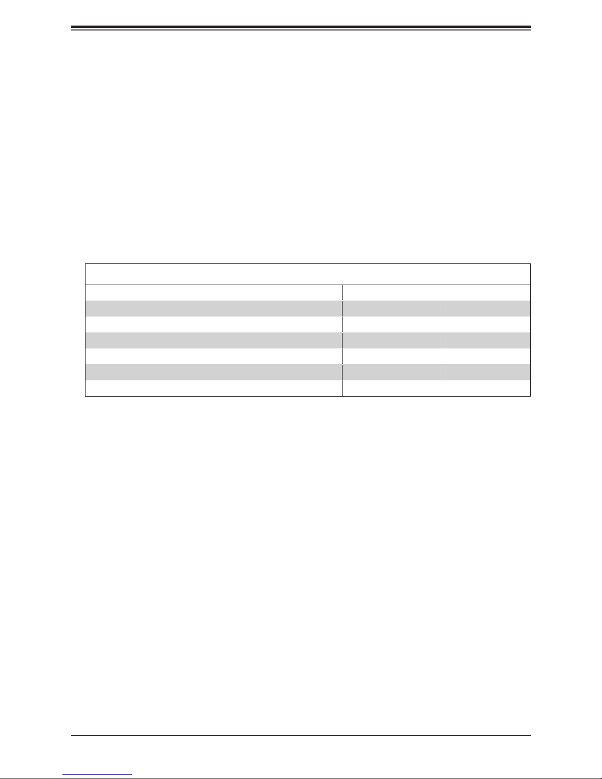
Main Parts List
Description Part Number Quantity
Backplane BPN-SAS-939HS One
Fans FAN-0145L4 Four
CPU passisve heatsink SNK-P0047PSR One per node
Air ow shroud MCP-310-93903-0N One per node
MicroLP module AOM-CGP-I2M One per node
Rail kit MCP-290-41803-0N One set
1.2 Unpacking the System
Inspect the box in which the server was shipped and note if it was damaged. If any equipment
appears damaged, le a damage claim with the carrier who delivered it.
7
SuperServer 5039MS-H12TRF User's Manual
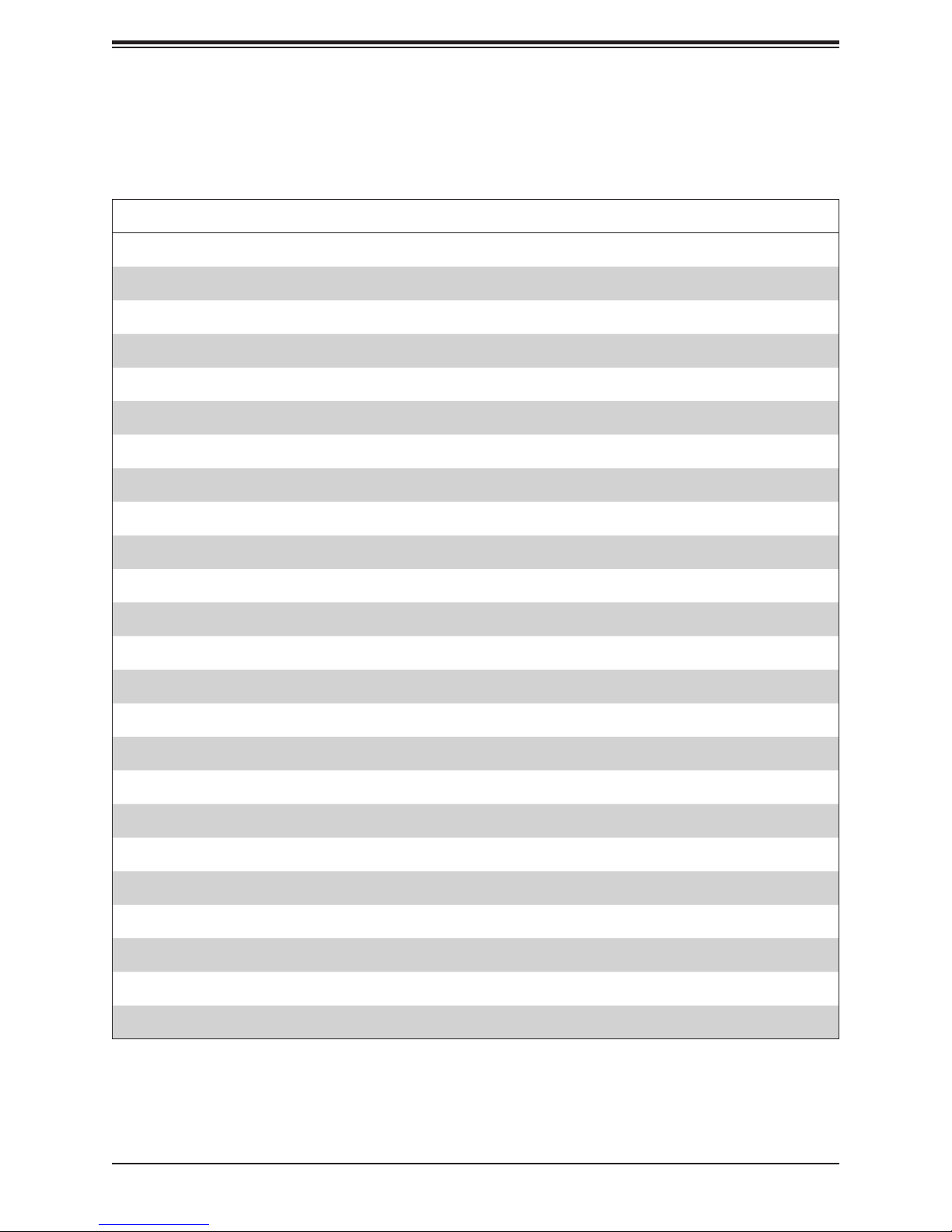
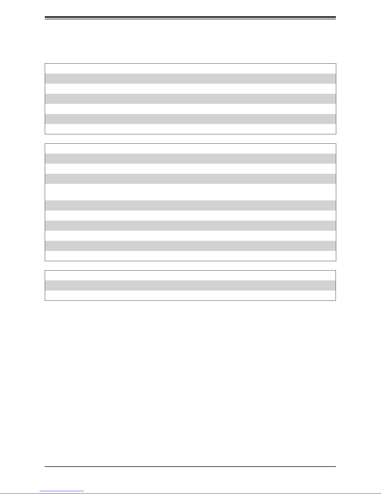
1.3 System Features
The following table provides you with an overview of the main features of the 5039MS-H12TRF.
Refer to Appendix C for additional specications.
System Features
Motherboard
X11SSE-F
Chassis
SC939HS-R2K04BP
CPU
Intel Xeon E3-1200 v5 (Skylake-S)
Socket Type
H4 LGA1151
Memory
Four DIMM ECC UDIMM VLP memory up to 64 GB
Chipset
Intel PCH C236 chipset
Expansion Slots
One MicroLP expansion module per node
Hard Drives
Internal, two 3.5" drives or four 2.5" drives, SATA3 or NVMe
Power
Dual 2000 W modules, 80+ Titanium level
Cooling
Four 9-cm exhaust fans; one airow shroud per node
Form Factor
3U rackmount
Dimensions
(WxHxD) 17.5 x 5.21 x 29.5 in. (444.5 x 132 x 749.3 mm)
8
Chapter 1: Introduction
1.4 Chassis Features
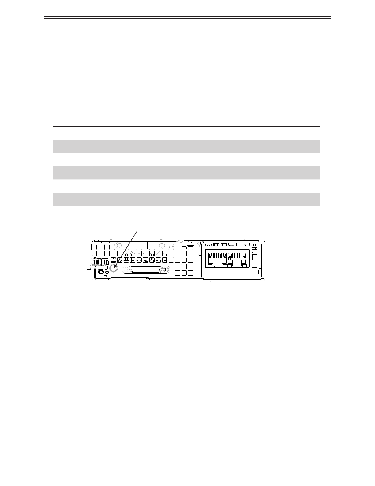
Power Button/LED
The main power button on each of the nodes functions as both an on/off switch and as a
status LED. Pressing the button will alternately power on or remove power from the node.
See the table below for the LED indications.
Node Power Button LED
LED Appearance Description
Green The node is powered on and operating normally
Solid Red The node is detecting an overheat condition
1Hz Blinking Red The node is detecting a fan failure
.25Hz Blinking Red The node is detecting a power failure
No Illumination The node is powered down
Node LED
Figure 1-1. Power Button/LED Indicator
(single node, front view)
9
SuperServer 5039MS-H12TRF User's Manual
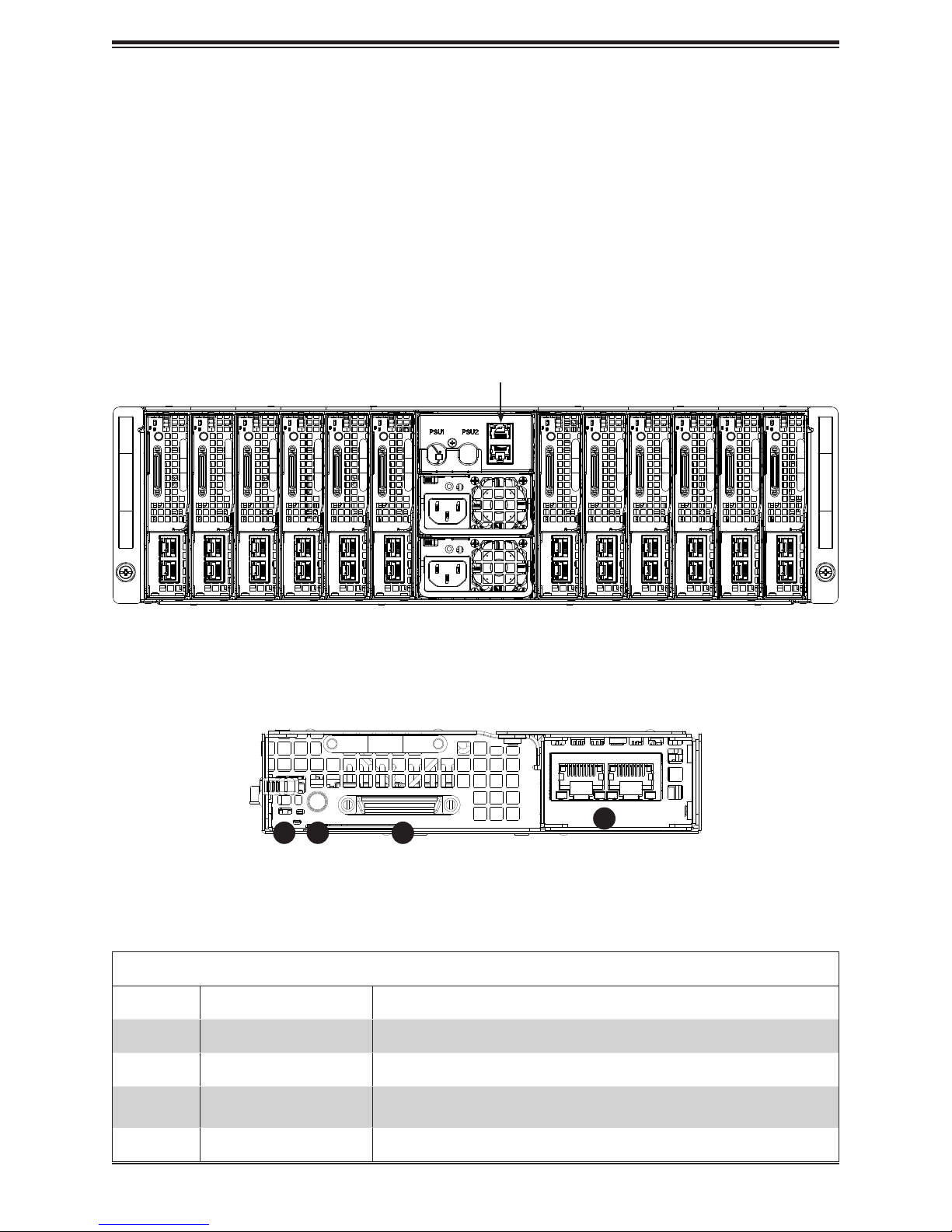
Front Features
The SC939HS-R2K04BP is a 3U chassis holding 12 discreet computing nodes. The chassis
front offers access to the dual power modules. It also includes two dedicated LAN ports to
provide IPMI management capabilitites for all nodes.
Note: The IPMI connections can be used in two ways.
• Cascade: Connect one to a managment device and the other to another server.
• Redundancy: For redundant IPMI managment, connect each port to a different subnetwork,
that is, each to a different switch.
Six Nodes Six Nodes
Two IPMI LAN Ports
Two Power Modules
Figure 1-2. Chassis Front View
1
32
4
Item Feature Description
1 UID button Unit identier button and LED
2 Power button Power button and LED
3 KVM port
4 LAN
Figure 1-3. Single Node Front View
Node Features
Connect the adapter to this port to provide two USB2 ports, one COM
port, and one serial port
Two LAN ports, by means of the MicroLP expansion module
10
Chapter 1: Introduction
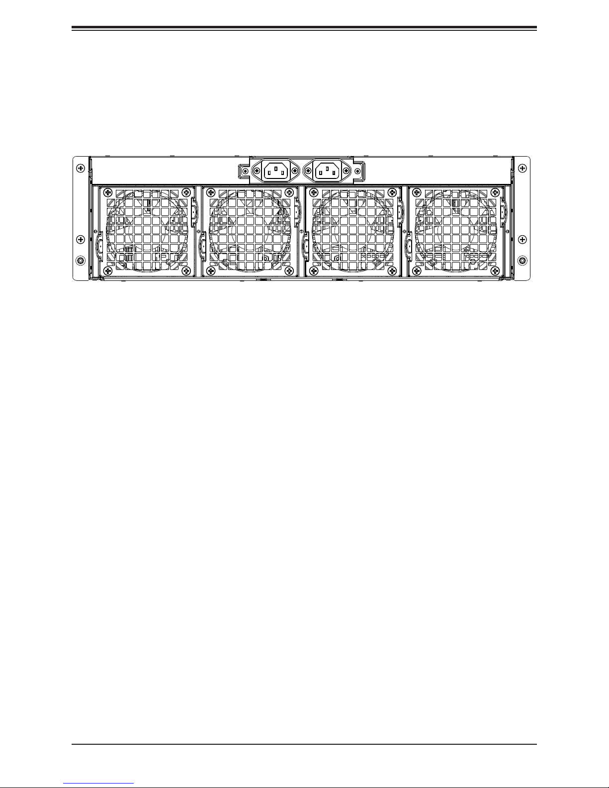
Rear Features
The illustration below shows the features included on the rear of the chassis.
Power Plugs (2)
Exhaust Fans (4)
Figure 1-4. Chassis Rear View
11
SuperServer 5039MS-H12TRF User's Manual
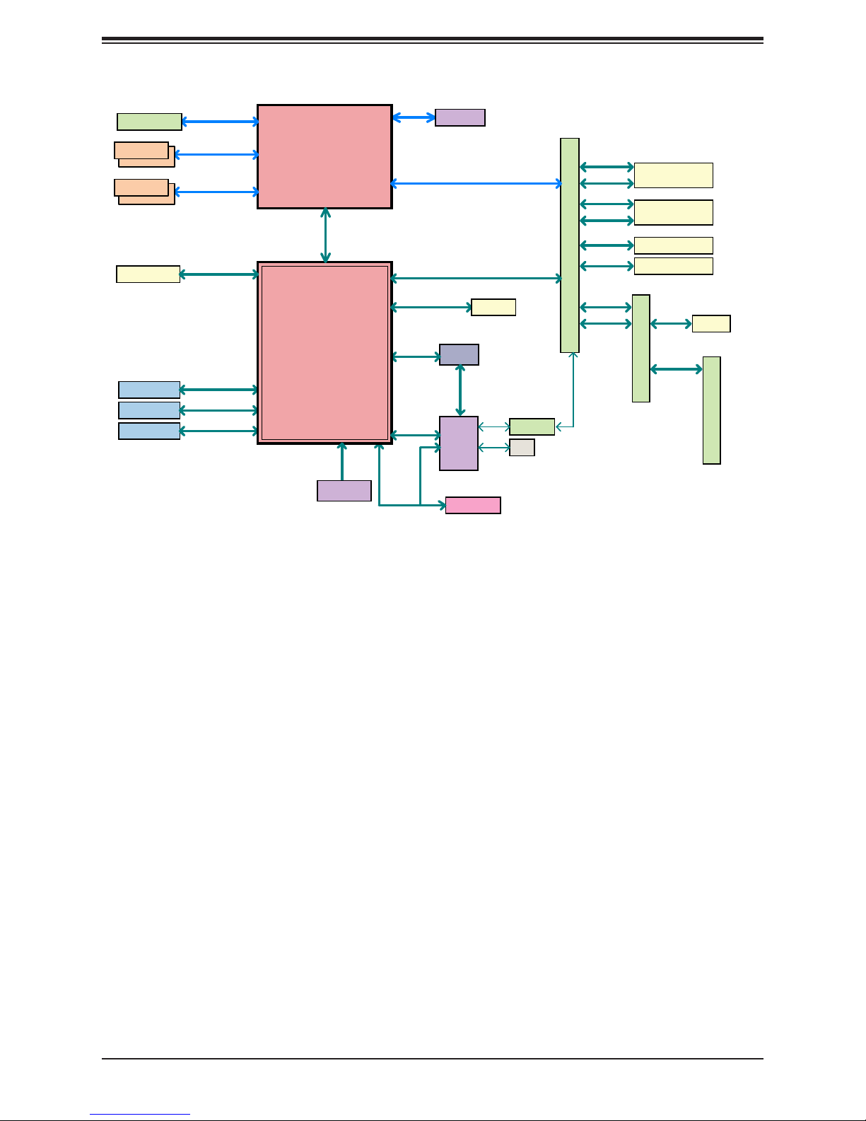
CPU MICRO-LP PCI-E 3.0 X8
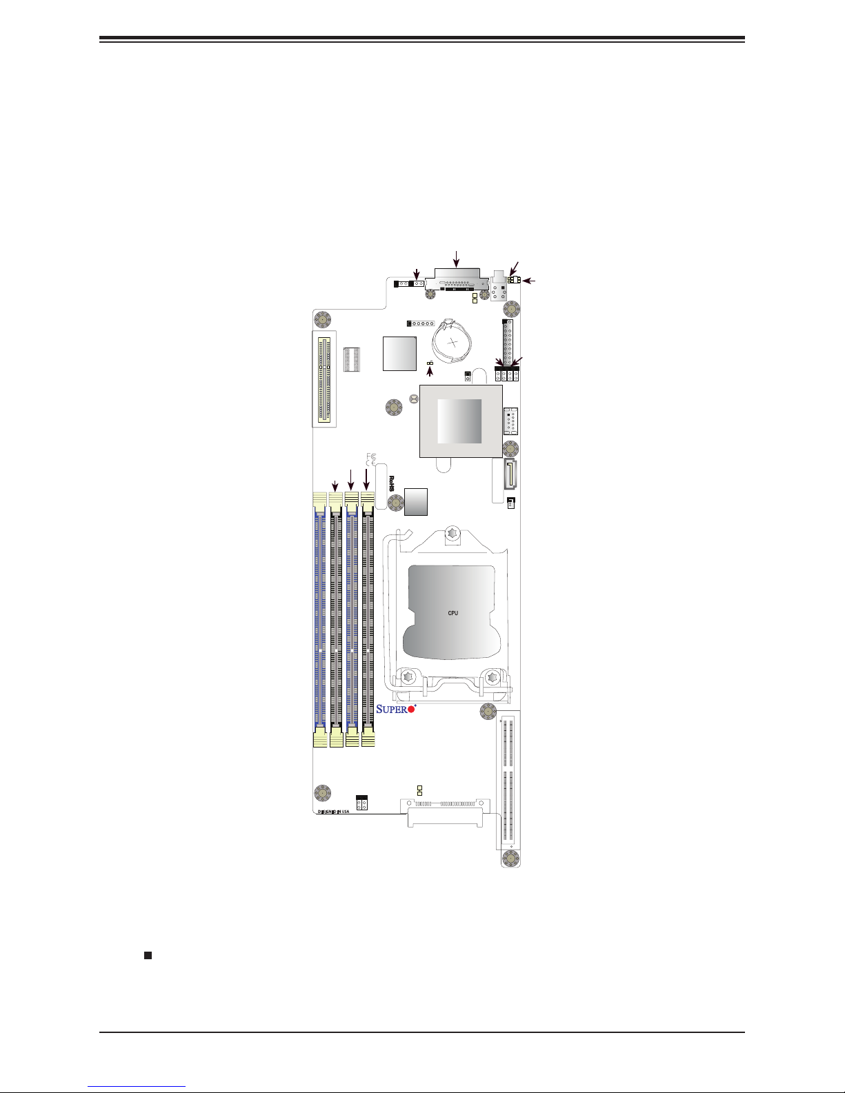
1.5 Motherboard Layout
Below is a layout of the X11SSE-F with jumper, connector and LED locations shown. See
the table on the following page for descriptions. For detailed descriptions, pinout information
and jumper settings, refer to Chapter 4.
JKVM1/VGA
J21
DIMMB1
DIMMB2
J21
MICRO-LP
JPG1
DIMMA1DIMMA2
BAR CODE
JPO1
JPG1
BMC
JBT1
JPO1
JBT1
LICENSE
BIOS
USB0/1
JKVM1/VGA
USB0/1
BT1
BT1
LED6
LED6
Intel PCH
JPME1
SW2
SW2
JTPM1
USB2 (3.0)
MAC CODE
LED5
JUIDB1
JTPM1
JWD1
JPME2
JPME1
I-SATA6
JSD1
LED5
JUIDB1
JPME2
JWD1
USB2
I-SATA6
JSD1
DIMMB2
DIMMB1
DIMMA2
Figure 1-4. Motherboard Layout
Notes:
• " " indicates the location of pin 1.
Rev. 1.01
DIMMA1
CPU
X11SSE-F
I-SATA0
I-SATA0
• Jumpers/LED indicators not indicated are used for testing only.
12
Chapter 1: Introduction
Motherboard Jumpers, Connectors, and LEDs
Jumper Description Default Setting
JBT1 CMOS Clear Open (Normal)
JPG1 VGA Enable/Disable Pins 1-2 (Enabled)
JPME1 ME Recovery Pins 1-2 (Normal)
JPME2 ME Manufacturing Mode Pins 1-2 (Normal)
JPO1 Power Fail Override Pins 2-3 (Disabled)
JWD1 Watch Dog Pins 1-2 (Reset)
Connector Description
BT1 Onboard Battery
I-SATA0 & I-SATA6 SATA 3.0 Connectors
J21 CPU Micro-LP PCI-E 3.0 x8 Slot
JKVM1/VGA
JSD1 SATA Disk On Module (DOM) Power Connector
JTPM1 Trusted Platform Module (TPM)/Port 80 Connector
JUIDB1 UID (Unit Identication) Switch
SW2 Power Switch/LED Indicator
USB0/1 Back panel USB 2.0 ports via KVM
USB2 USB 3.0 internal connector
KVM/VGA (Monitor) (UART) Connector for Remote Console Redirection or Remote
Network Interface
LED Description State: Status
LED5 Rear UID LED Blue: On; Unit Identied
LED6 BMC Heartbeat LED Green: Blinking; BMC Normal
13
SuperServer 5039MS-H12TRF User's Manual
PCIe x8 MLP SLOT
DIMMA1
DIMMA2
DIMMB1
DIMMB2
1 X SATA-III DOM
1 X USB A-type
2 X USB 2.0 Rear
2 X USB 2.0 MLP
PCIe3.0_x8
8.0GT/s
DDR4 (CHA)
2133/1866/1600MHz
DDR4 (CHB)
2133/1866/1600MHz
SATA-III
6Gb/s
USB3.0
5Gbps
USB2.0
480Mbps
USB2.0
480Mbps
Port [19]
USB3[5] USB2[5]
USB2[1/2]
USB2(3/4]
LGA1151
(Socket-H4)
PCH-H
C236
FLASH
SPI 128Mb
x4 DMI
8GT/s
IMVP8
Port [10,15-18]
Port [9]
Port [14]
SPI
LPC
SVID
SATA-III
6Gb/s
SGPIO
PCIe3.0_x1
8.0GT/s
IMVP8
PCIe3.0_x8
8.0GT/s
5 x SATA-III
6Gb/s
SGPIO
Decoder
SMBUS
AST2400
TPM1.2 Header
I-SATA0
RGMII
RTL8211FS
VGA
AOM-BPN-MC12S
1000BASE-X
1000BASE-X
1Gb/s
SATA-III
6Gb/s
PCIe3.0 x4
8.0GT/s
SATA
6Gb/s
PCIe3.0 x4
8.0GT/s
SATA-III
6Gb/s
SATA-III
6Gb/s
SATA-III
6Gb/s
1Gb/s
-III
I-SATA[2]/NVMe1
I-SATA[3]/NVMe2
I-SATA[4]
I-SATA[5]
SATA-III
6Gb/s
1000BASE-X
1Gb/s
AOM-PDB-MC12S
I-SATA[1]
BPN-SAS-939HS
Figure 1-5. Intel PCH C236 Chipset: System Block Diagram
Note: This is a general block diagram and may not exactly represent the features on your
motherboard. See the System Specications appendix for the actual specications of your
motherboard.
14

Chapter 2 Installation in a Rack
Chapter 2
Installation in a Rack
This chapter provides advice and instructions for mounting your system in a rack.
2.1 Preparing for Setup
The box in which the system was shipped should include the hardware needed to install it
into the rack. Please note the precautions in this chapter and Appendix B
Choosing a Setup Location
• The system should be situated in a clean, dust-free area that is well ventilated. Avoid areas
where heat, electrical noise and electromagnetic elds are generated. It will also require
a grounded AC power outlet nearby.
• Leave enough clearance in front of the rack so that you can open the front door completely
(~25 inches) and approximately 30 inches of clearance in the back of the rack to allow
sufcient space for airow and access when servicing.
• This product should be installed only in a Restricted Access Location (dedicated equipment
rooms, service closets, etc.).
• This product is not suitable for use with visual display workplace devices acccording to §2
of the the German Ordinance for Work with Visual Display Units.
Rack Precautions
• Ensure that the leveling jacks on the bottom of the rack are extended to the oor so that
the full weight of the rack rests on them.
• In single rack installations, stabilizers should be attached to the rack. In multiple rack in-
stallations, the racks should be coupled together.
• Always make sure the rack is stable before extending a server or other component from
the rack.
• Extend only one server or component at a time - extending two or more simultaneously
may cause the rack to become unstable.
15

SuperServer 5039MS-H12TRF User's Manual
Server Precautions
• Review the electrical and general safety precautions in Chapter 3.
• Determine the placement of each component in the rack before you install the rails.
• Install the heaviest server components at the bottom of the rack rst and then work your
way up.
• Use a regulating uninterruptible power supply (UPS) to protect the server from power
surges and voltage spikes and to keep your system operating in case of a power failure.
• Allow any drives and power supply modules to cool before touching them.
• When not servicing, always keep the front door of the rack and all covers/panels on the
servers closed to maintain proper cooling.
Rack Mounting Considerations
Ambient Operating Temperature
If installed in a closed or multi-unit rack assembly, the ambient operating temperature of
the rack environment may be greater than the room's ambient temperature. Therefore,
consideration should be given to installing the equipment in an environment compatible with
the manufacturer’s maximum rated ambient temperature (Tmra).
Airow
Equipment should be mounted into a rack so that the amount of airow required for safe
operation is not compromised.
Mechanical Loading
Equipment should be mounted into a rack so that a hazardous condition does not arise due
to uneven mechanical loading.
Circuit Overloading
Consideration should be given to the connection of the equipment to the power supply circuitry
and the effect that any possible overloading of circuits might have on overcurrent protection
and power supply wiring. Appropriate consideration of equipment nameplate ratings should
be used when addressing this concern.
16
Chapter 2 Installation in a Rack
Reliable Ground
A reliable ground must be maintained at all times. To ensure this, the rack itself should be
grounded. Particular attention should be given to power supply connections other than the
direct connections to the branch circuit (i.e. the use of power strips, etc.).
To prevent bodily injury when mounting or servicing this unit in a rack, you must take
special precautions to ensure that the system remains stable. The following guidelines
are provided to ensure your safety:
• This unit should be mounted at the bottom of the rack if it is the only unit in the rack.
• When mounting this unit in a partially lled rack, load the rack from the bottom to the top
with the heaviest component at the bottom of the rack.
• If the rack is provided with stabilizing devices, install the stabilizers before mounting or
servicing the unit in the rack.
• Slide rail mounted equipment is not to be used as a shelf or a work space.
Stability hazard. The rack stabilizing mechanism must be in place, or the rack must
be bolted to the oor before you slide the unit out for servicing. Failure to stabilize the
rack can cause the rack to tip over.
17
SuperServer 5039MS-H12TRF User's Manual
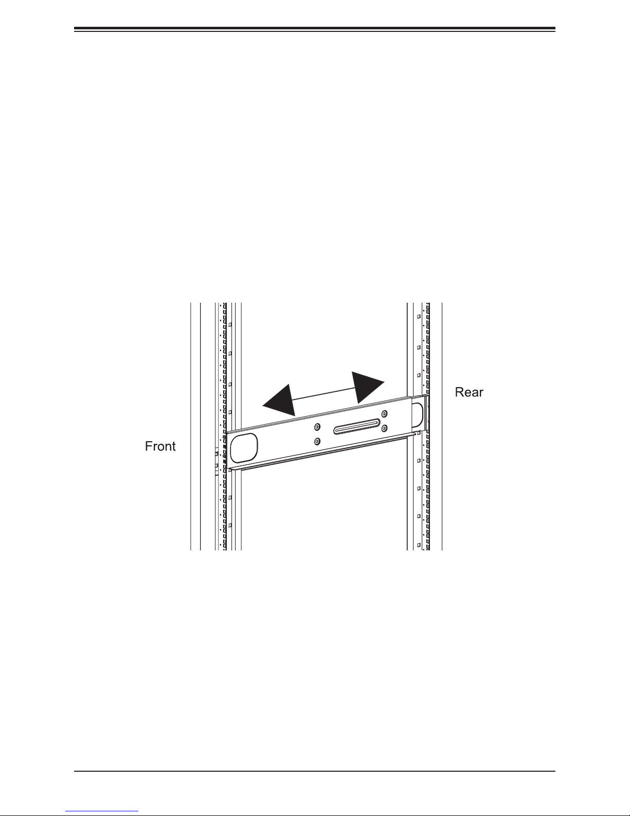
2.2 Installing the Rails
There are a variety of rack units on the market, which may require a slightly different assembly
procedure. The following is a basic guideline for installing the system into a rack. Also refer
to the installation instructions that came with the rack.
This rail set ts a rack between 28" and 33.5" deep. Do not use a two post "telco" type rack.
1. Identify the left rail set and right rail set, as they are different.
2. In each rail set, the two sections are screwed together to keep them immobile during
shipping. Release these screws just enough to allow the rail sections to slide apart. Note
the arrow on the rail, which indicates the end that attaches to the front of the rack.
3. Slide the rail sections apart far enough to match the depth of the rack. Hang the hooks
on the rear end of the rail onto the square holes in the rear of the rack.
4. Push the two square pegs on the front of the rail through the square holes in the front
of the rack. Be sure the rail is level, front to back. Secure the front of the rail to the rack
with one athead screw.
5. Tighten the screws that keep the two rail sections from sliding.
6. Install the other rail set. Be sure it is even with the rst.
7. With one person on either side, lift the system and slide it onto the installed rails.
8. After pushing the enclosure all the way into the rack, use the thumbscrew on each side
of the server to lock it into place.
Figure 2-1. Installing the Left Rail
18

Chapter 3: Maintenance and Component Installation
Chapter 3
Maintenance and Component Installation
This chapter provides instructions on installing and replacing main system components. To
prevent compatibility issues, only use components that match the specications and/or part
numbers given.
Installation or replacement of most components require that power rst be removed from the
system. Please follow the procedures given in each section.
3.1 Removing Power
Use the following procedure to ensure that power has been removed from the system. This
step is necessary when removing or installing non hot-swap components or when replacing
a non-redundant power supply.
1. Use the operating system to power down the system.
2. After the system has completely shut-down, disconnect the AC power cord(s) from the
power strip or outlet. (If your system has more than one power supply, remove the AC
power cords from all power supply modules.)
3. Disconnect the power cord(s) from the power supply module(s).
19
SuperServer 5039MS-H12TRF User's Manual
3.2 Accessing the System
Top Cover
A portion of the chassis top is removable to allow access to the system fans and backplane.
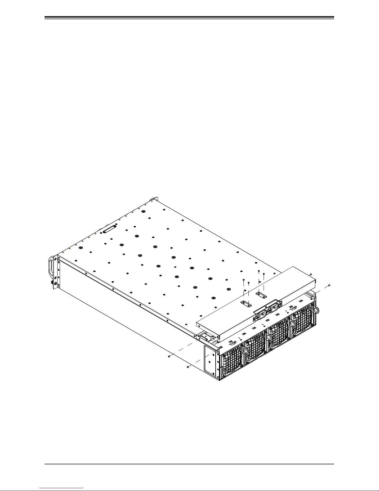
Removing the Top Cover
1. Remove power from the system as described in Section 3.1.
2. Remove the screws securing the cover to the chassis--four on top and two on each
side. See Figure 3-1.
3. Lift the cover from the chassis.
Caution: Except for short periods of time, do not operate the server without the cover in place.
The chassis cover must be in place to allow for proper airow and to prevent overheating.
Figure 3-1. Removing the Chassis Cover
20
Chapter 3: Maintenance and Component Installation
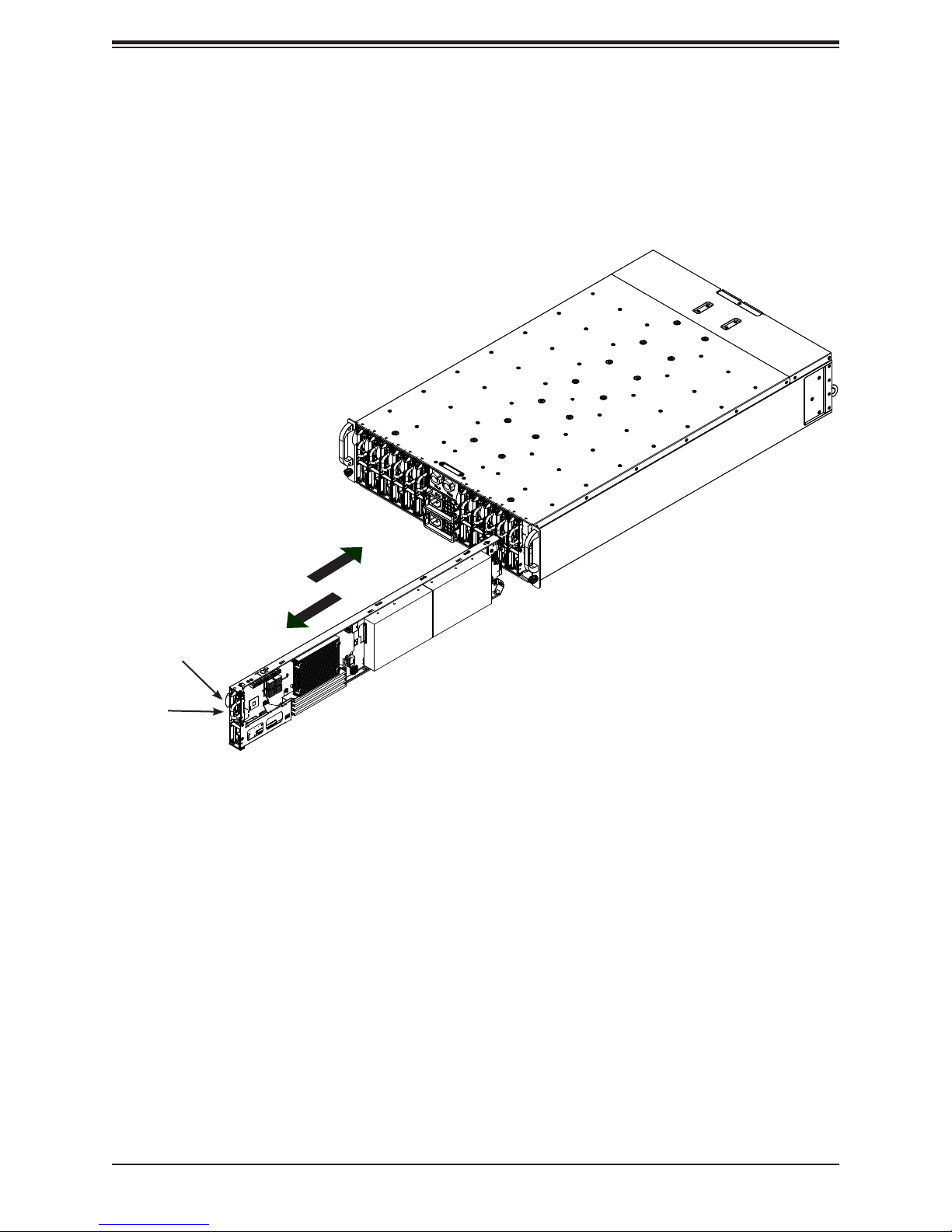
Removing and Installing Motherboard Nodes
The system comes features twelve removable nodes. Each node contains an individual
motherboard and hard drives mounted on a sled, which allows it to easily be installed and
removed from the chassis.
Release Tab
Handle
Figure 3-2. Removing/Installing a Node
Removing Nodes from the System
1. Power-down the individual node by pressing that node's power button.
2. Press and hold down the release tab on the front of the node.
3. Use the node's handle to pull the node from the system.
Caution: Except for short periods of time while swapping nodes, do not operate the server
with the node bays empty. In the unlikely event of a node failure, remove the failed node and
replace it with the dummy node that was included with the system.
21
SuperServer 5039MS-H12TRF User's Manual
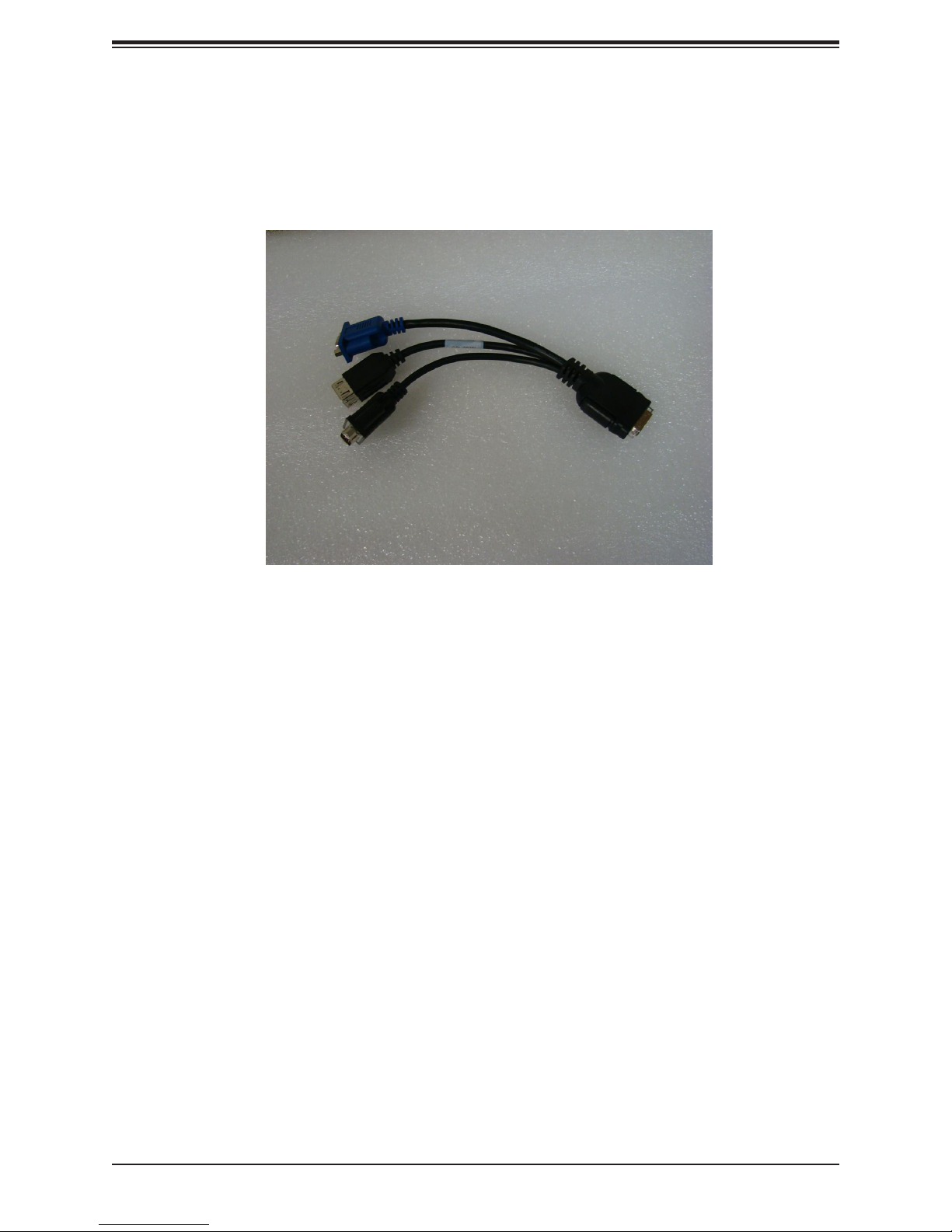
Connecting to a Node
USB, COM, and serial port capabilties can be added to any node through the KVM port on
the front. Plug in the adapter (dongle).
Figure 3-3. Adapter to Provide USB, COM, and Serial Ports
22
Chapter 3: Maintenance and Component Installation
3.3 Motherboard Components
Processor and Heatsink Installation
Follow the procedures in this section to install a processor (CPU) and heatsink onto the
motherboard.
Notes:
• Be sure to use an Intel-certied multi-directional heatsink.
• When receiving a motherboard without a processor pre-installed, make sure that the plastic
protective socket cover is in place and none of the socket pins are bent; otherwise, contact
your retailer immediately.
• Refer to the Supermicro website for updates on CPU support.
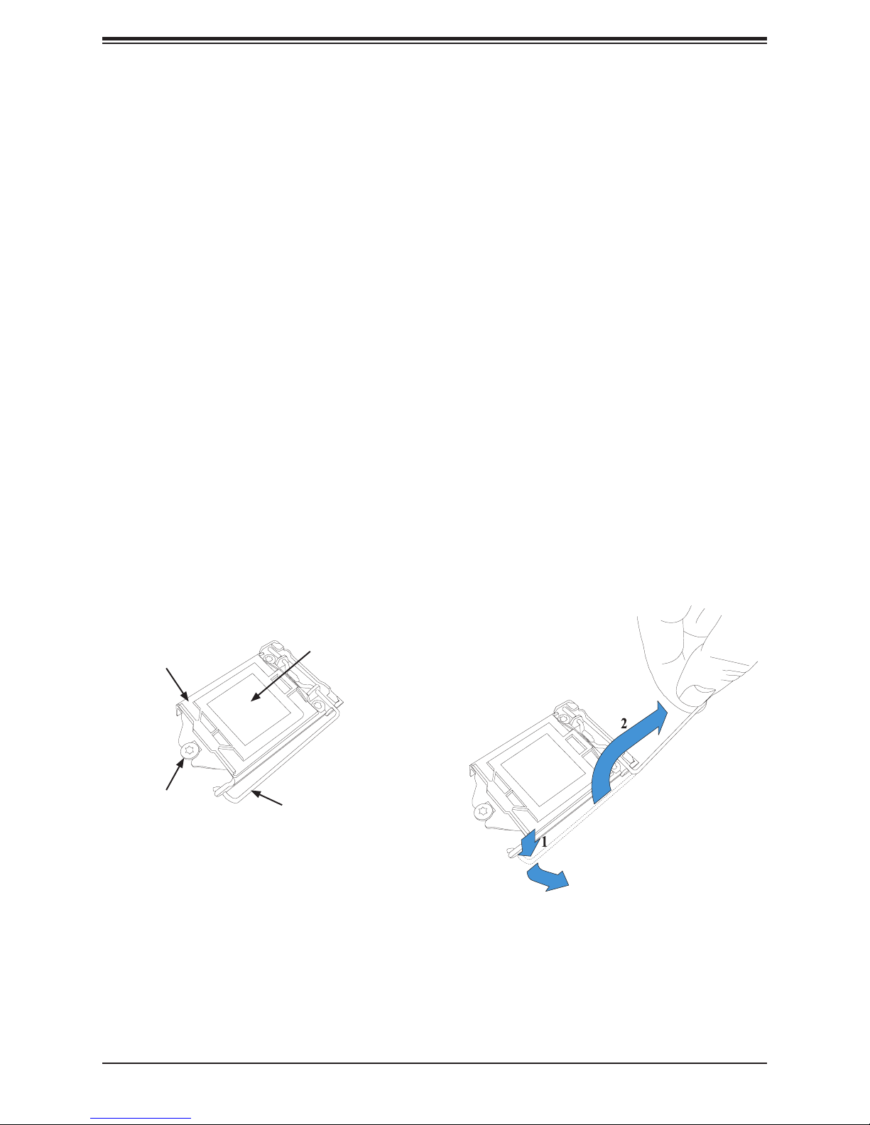
Installing the Processor
1. Remove power from the system as described in Section 3.1.
2. Press the locking lever down and outward to release it, then lift it fully open. The load
plate slides loose from the retaining post.
Plastic Protective
Load Plate
Retaining Post
Cover
Locking Lever
Figure 3-2. Releasing the Locking Lever
23
SuperServer 5039MS-H12TRF User's Manual
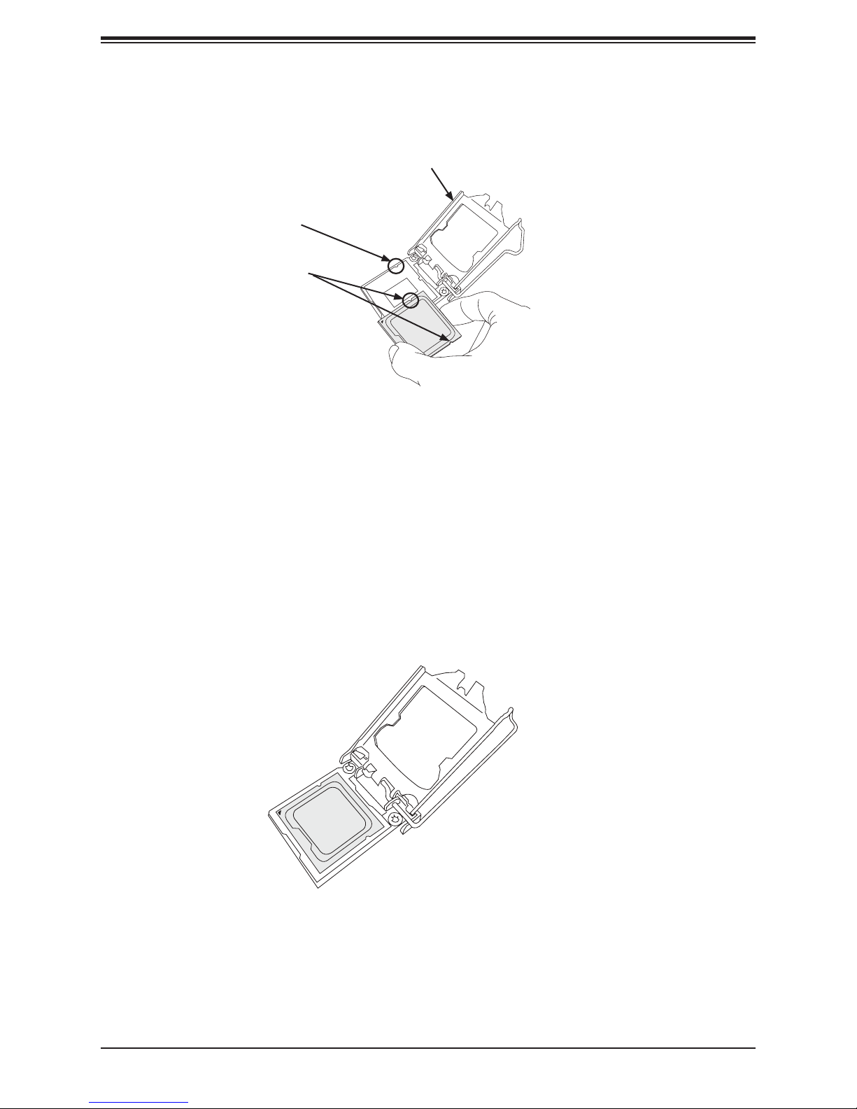
3. Lift open the load plate.
Load Plate Open
Socket Key
Processor Notches
Figure 3-3. Placing the Processor into the Socket
4. Use your thumb and your index nger to hold the edges of the processor. Do not touch
the socket contacts or the bottom of the processor. Align the notches (the semi-circle
cutouts) on the processor with the socket keys.
5. Once aligned, carefully place the processor into the socket. Do not drop the processor
on the socket, move or rub the processor against the socket or against any socket pins,
as this may damage the components. Make sure the processor is properly aligned and
seated in the socket, checking all corners.
Figure 3-4. Seating the Processor
24
Chapter 3: Maintenance and Component Installation
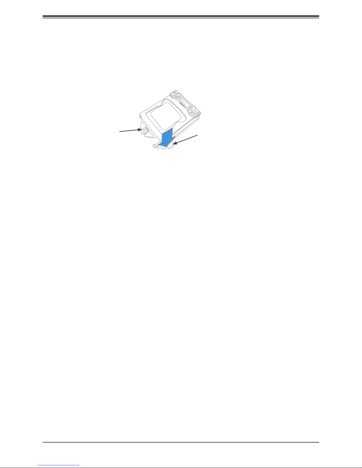
6. Gently close the load plate onto the processor. The plastic protective cover on the load
plate will pop off. Save the cover to protect the socket if the processor is ever removed.
7. Making sure the slot in the load plate slides under the retaining post, close and latch the
locking lever.
Load Plate slot under
Retaining Post
Locking Lever
latched into place
Figure 3-5. Securing the Processor with the Socket Lever
25
SuperServer 5039MS-H12TRF User's Manual
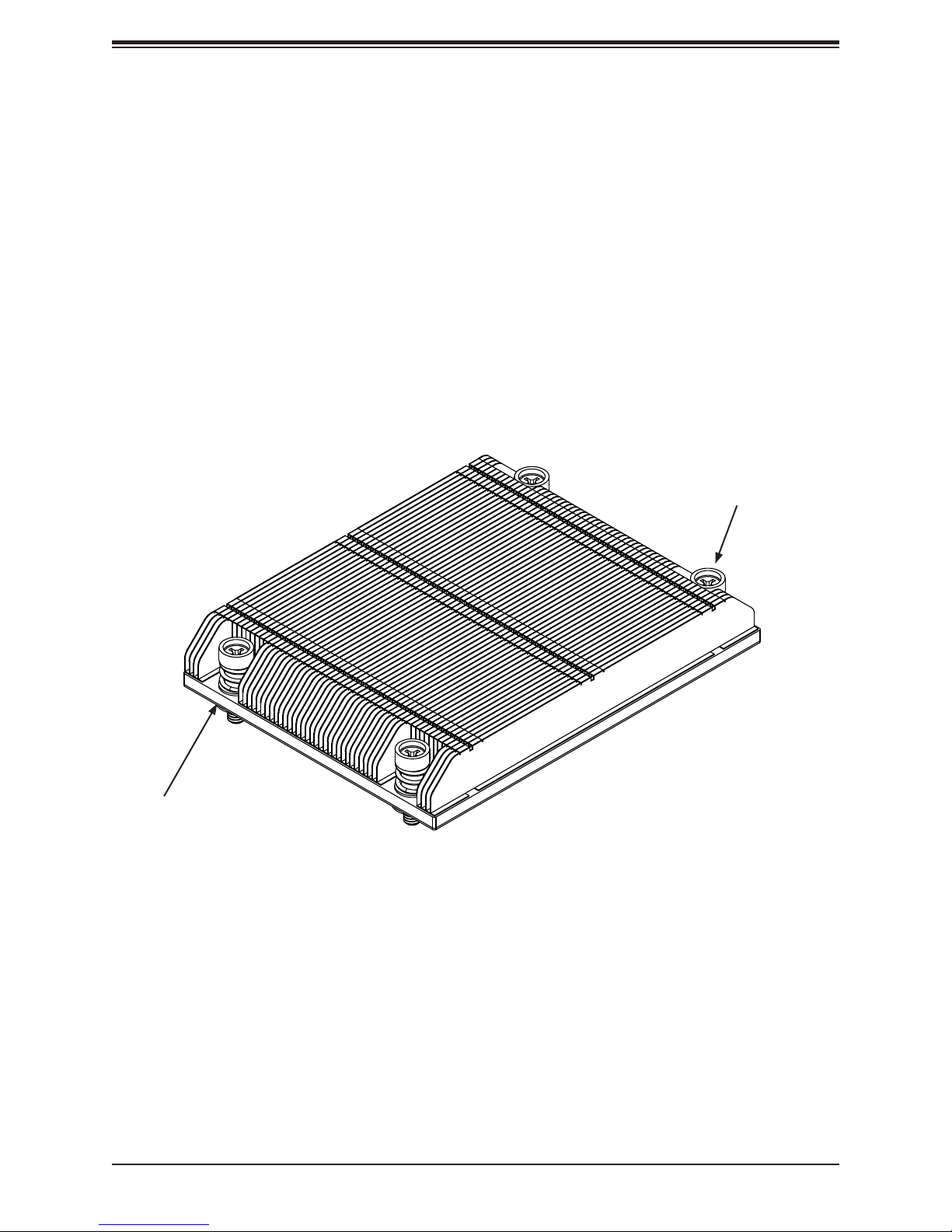
Installing a Heatsink
A passive type heatsink is used on the X11SSE-F motherboard.
Note: Do not apply any thermal grease to the heatsink or the CPU; the required amount has
already been applied.
1. Place the heatsink on top of the CPU so that the four mounting holes are aligned with
those on the heatsink retention mechanism.
2. Screw in two diagonal screws (i.e. the #1 and the #2 screws) until they are just snug.
Do not fully tighten the screws or you may damage the CPU.
3. Add the two remaining screws then nish the installation by fully tightening all four
screws (be careful not to overtighten).
Screw#1
Screw#2
Figure 3-5. Installing/Removing the Heatsink
26
Chapter 3: Maintenance and Component Installation
Removing a Heatsink
We do not recommend removing the heatsink. If necessary, please follow the instructions
below to prevent damage to the CPU or the CPU socket.
1. Unscrew and remove the heatsink screws from the motherboard in the sequence as
show in the gure above.
2. Hold and gently pivot the heatsink back and forth to loosen it from the CPU. (Do not use
excessive force when dislodging the heatsink!)
3. Once the heatsink is loose, remove it from the CPU.
4. Clean the surface of the CPU and the heatsink to get rid of the old thermal grease.
Reapply the proper amount of thermal grease to the surface before you re-install the
heatsink.
Memory Installation
Memory Support
The X11SSE-F supports up to 64GB of ECC DDR4-2133/1866/1600/1333 unbuffered
(UDIMM) memory in four memory slots. Populating two adjacent slots at a time with memory
modules of the same size and type will result in interleaved (128-bit) memory, which is faster
than non-interleaved (64-bit) memory.
Check the Supermicro website for possible updates to memory support.
DIMM Module Population Conguration
For optimal memory performance, follow the table below when populating memory.
Memory Module Population for Optimal Performance
Number of
DIMMs
2 DIMMs DIMMB2/DIMMA2
4 DIMMs DIMMB2/DIMMA2, DIMMB1/DIMMA1
Memory Population Conguration Table
(For memory to work properly, please follow the instructions below.)
DIMM Slots
per Channel
2
DIMM
Type
Unbuffered
DDR4 VLP
Memory Module Population
POR Speeds
(MHz)
2133,1866,
1600
Ranks per
DIMM
SR, DR 6 SPS 1.2V1
27
Layer
Count
FW Base
Supported
Voltage
SuperServer 5039MS-H12TRF User's Manual
Memory Module Population
Max Memory
Possible
Single Rank
UDIMM
Dual Rank
UDIMMs
4GB DRAM
Technology
16GB
(4x 4GB DIMMs)
32GB
(4x 8GB DIMMs)
8GB DRAM
Technology
32GB
(4x 8GB DIMMs)
64GB
(4x 16GB DIMMs)
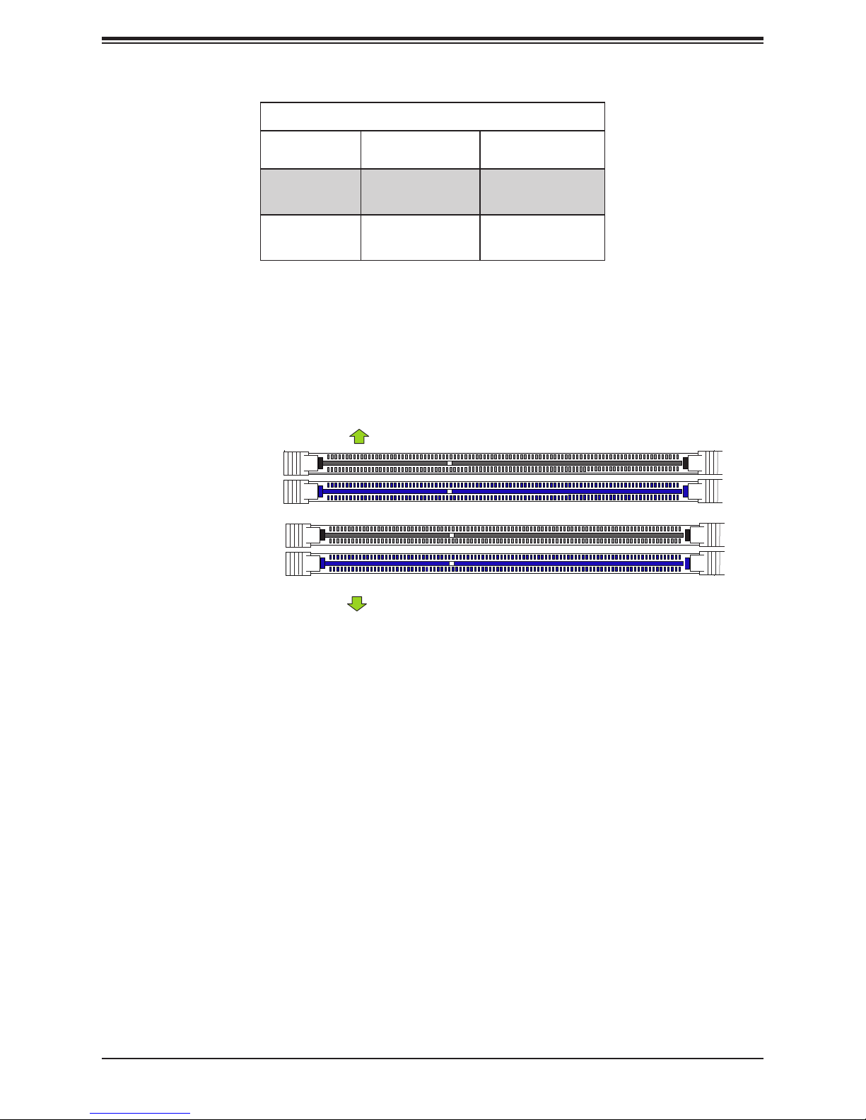
DIMM Module Population Sequence
When installing memory modules, the DIMM slots must be populated in the following order:
DIMMB2, DIMMA2, then DIMMB1, DIMMA1. The blue slots must be populated rst.
Towards the CPU
DIMMA1
DIMMA2 (Blue Slot)
DIMMB1
DIMMB2 (Blue Slot)
Towards the edge of the motherboard
Note: Be sure to use memory modules of the same type and speed on the motherboard.
Mixing of memory modules of different types and speeds is not allowed.
28
Chapter 3: Maintenance and Component Installation
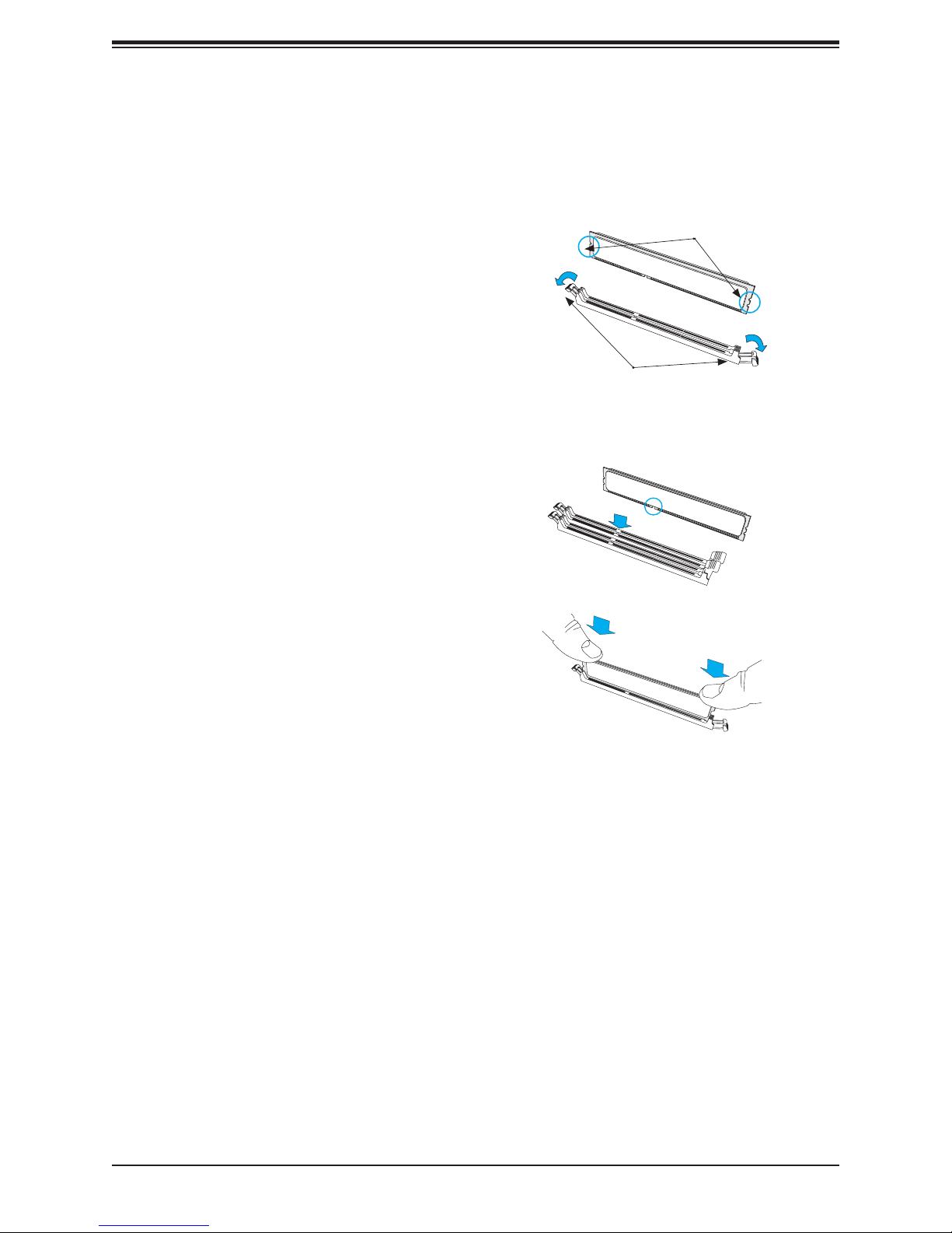
Install Procedure
Installing Memory
1. Remove power from the system as described in Section 3.1.
2. Starting with P1-DIMMA1, push the
release tabs outwards on both ends of
the DIMM slot to unlock it.
3. Align the key of the DIMM with the
receptive point on the memory slot and
with your thumbs on both ends of the
module, press it straight down into the
slot until the module snaps into place.
Notches
Release Tabs
Press both notches straight
down into the memory slot.
4. Press the release tabs to the locked position to secure the DIMM module into the slot.
5. Repeat the procedure for the remaining DIMM modules in the order detailed in the
previous section.
Caution: Exercise extreme caution when installing or removing memory modules to prevent
damage to the DIMMs or slots.
Note: Visit the product page on the Supermicro website for possible updates to memory
support (www.supermicro.com).
Removal Procedure
To remove a DIMM module, unlock the release tabs then pull the module from the slot.
29

SuperServer 5039MS-H12TRF User's Manual
Expansion Module
Each of the twelve nodes includes a single MicroLP expansion module providing two LAN
connections. Currently, there are four supported for the 5039MS-H12TRF system.
Two LAN ports (standard), AOM-CGP-i2M
Two QSFP + USB ports (optional), AOM-CIBF-M1M
One SFP+ USB ports (optional), AOM-CTG-i1SM
Two 10G baseT ports (optional), AOM-CTGS-i2T
The MicroLP expansion module is inserted into a riser card and secured to two brackets as
shown below. This assembly is inserted into the expansion slot on the motherboard and the
rear bracket is secured to the rear of the node chassis.
Expansion Card
Riser Card
Bracket
Note: This exploded view of the expansion
module is for information only. The
expansion card, riser card and mounting
bracket come pre-assembled and installed
Figure 3-4. MicroLP Expansion Module Assembly
30
 Loading...