

Supermicro SuperServer 4027GR-TR, SuperServer 4027GR-TRT Quick Reference Manual
http://www.supermicro.com
MNL-1582-QRG
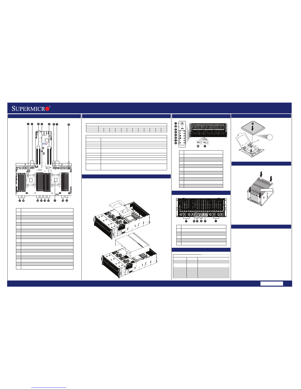
Board Layout
SuperServer 4027GR-TRT/TR Quick Reference Guide
BIOS Beep Codes
Beep Code/LED
5 short beeps +
1 long beep
Memory
5 long beeps
No Con-In or
No Con-Out
devices
CPU Installation
Front view & Interface
Heatsink Installation
MEMORY
Caution
Align CPU to socket;
install CPU straight down
No memory detected in the system
NOTE:
Do not bend pin inside socket
!
SAFETY INFORMATION
IMPORTANT: See installation instructions and safety warning
before connecting system to power supply.
http://www.supermicro.com/about/policies/safety_information.cfm
WARNING:
To reduce risk of electric shock/damage to equipment,
disconnect power from server by disconnecting all power
cords from electrical outlets.
If any CPU socket empty, install protective plastic CPU cap
CAUTION:
Always be sure all power supplies for this system have
the same power output. If mixed power supplies are
installed, the system will not operate.
For more information go to :
http://www.supermicro.com/support
!
!
!
1 beep
Refresh
Ready to boot
Processors and Memory Module Population for Optimal Performance
Number of
CPUs + DIMMs
CPU and Memory Population Configuration Table
(For memory to work properly, follow the instructions below)
1 CPU & 2 DIMMs
CPU1 & P1-DIMMA1/P1-DIMMB1
1 CPU & 4 DIMMs
1 CPU & 5~8 DIMMs
2 CPUs & 4 DIMMs
2 CPUs & 6 DIMMs
CPU1 & P1-DIMMA1/P1-DIMMB1, P1-DIMMC1/P1-DIMMD1
CPU1 & P1-DIMMA1/P1-DIMMB1, P1-DIMMC1/P1-DIMMD1, P1-DIMMA2/P1-DIMMB2, P1-DIMMC2/P1-DIMMD2
CPU1 + CPU2 & P1-DIMMA1/P1-DIMMB1, P2-DIMME1/P2-DIMMF1
CPU1 + CPU2 & P1-DIMMA1/P1-DIMMB1, P2-DIMME1/P2-DIMMF1, P1-DIMMC1/P1-DIMMD1
2 CPUs & 8 DIMMs
2 CPUs & 9~12 DIMMs
2 CPUs & 13~24 DIMMs
CPU1 + CPU2 & P1-DIMMA1/P1-DIMMB1, P2-DIMME1/P2-DIMMF1, P1-DIMMC1/P1-DIMMD1, P2-DIMMG1/P2-DIMMH1
CPU1/CPU2 & P1-DIMMA1/P1-DIMMB1, P2-DIMME1/P2-DIMMF1, P1-DIMMC1/P1-DIMMD1, P2-DIMMG1/P2-DIMMH1
P1-DIMMA2/P1-DIMMB2, P2-DIMME2/P2-DIMMF2
CPU1/CPU & P1-DIMMA1/P1-DIMMB1, P2-DIMME1/P2-DIMMF1, P1-DIMMC1/P1-DIMMD1, P2-DIMMG1/P2-DIMMH1,
P1-DIMMA2/P1-DIMMB2, P2-DIMME2/P2-DIMMF2, P1-DIMMC2/P1-DIMMD2, P2-DIMMG2/P2-DIMMH2,
P1-DIMMA3/P1-DIMMB3, P2-DIMME3/P2-DIMMF3, P1-DIMMC3/P1-DIMMD3, P2-DIMMG3/P2-DIMMH3
Processors and their Corresponding Memory Modules
CPU#
Corresponding DIMM Modules
CPU 1 P1-DIMM
A1
CPU 2 P2-DIMM
E1
A2E2A3
E3
Beep Codes
1. Place heatsink on top of installed CPU
2. Line up the four screws to socket
3. Push down heatsink and screw down as shown
(cross pattern, in order: A, B, C, D)
4. NOTE: Only use 6-8 lb/f of torque; otherwise, hand-tighten
each screw, to avoid damaging the system
Rear View
Power Button
Reset Button
Power LED
Device Activity LED
LAN1 LED
LAN2 LED
Information LED
Power Failure Button
Hard Drive Signal
Hard Drive Fail
Description
No.
5
3
7
6
1
2
3
4
5
6
7
8
9
10
Description
No.
CPU2
S-SATA1~4: Intel SATA 2.0 Connectors 0~3 (from Intel SCU)
J33/J34 : Slots for Riser Cards (RSC-X9DRG-O) slot
JBT1= CMOS Clear
J32/J31 : Slots for Riser Cards (RSC-X9DRG-O) slot
I-SATA0~1: Intel SATA 3.0 Connectors 0/1 (from Intel AHCI)
I-SATA2~5: Intel SATA 2.0 Connectors 2/3/4/5 (from Intel AHCI)
JSD1/JSD2 = SATA DOM Power
P1-DIMMA1(Blue)/P1-DIMMA2/P1-DIMMA3 slot
P1-DIMMB1(Blue)/P1-DIMMB2/P1-DIMMB3 slot
CPU1 (Install CPU1 first)
P1-DIMMD1(Blue)/P1-DIMMD2/P1-DIMMD3 slot
P1-DIMMC1(Blue)/P1-DIMMC2/P1-DIMMC3 slot
P1-DIMME1(Blue)/P1-DIMME2/P1-DIMME3 slot
P1-DIMMF1(Blue)/P1-DIMMF2/P1-DIMMF3 slot
P1-DIMMH1(Blue)/P1-DIMMH2/P1-DIMMH3 slot
P1-DIMMG1(Blue)/P1-DIMMG2/P1-DIMMG3 slot
1
2
3
4
5
6
7
8
9
10
11
12
13
14
15
16
17
Description
No.
1
2
3
4
5
Power Supplies
VGA Port
LAN1 & LAN2
(10GbE SFP+ Port/1G Port) (X9DRG-OTG/OF)
USB 0/1, 2/3 Ports
Dedicated LAN for IPMI
Con-In: USB or PS/2 keyboard, PCI or
Serial Console Redirection, IPMI KVM or SOL
Con-Out: Video Controller, PCI or Serial
Console Redirection, IPMI SOL
Message
Description
4
B1F1B2F2B3F3C1G1C2G2C3G3D1H1D2H2D3
H3
1 CPU & 9~12 DIMMs
CPU1/CPU
P1-DIMMA1/P1-DIMMB1, P1-DIMMC1/P1-DIMMD1, P1-DIMMA2/P1-DIMMB2, P1-DIMMC2/P1-DIMMD2
P1-DIMMA3/P1-DIMMB3, P1-DIMMC3/P1-DIMMD3
SW1
JPW10
J21
SP1
JBT1
JITP0
JSD2
JSD1
JTPM1
I_SATA1
I-SATA0
I-SATA2
I_SATA3
JF1
JWD1
JBR1
JPME1
JPL1
JPG1
J29
JPB1
J30
LE1
LE4
DM1
FAN8
FAN6
FAN7
FAN5
FAN1
FAN3
FAN4
JSPK1
JL1
JOH1
JPLD1
JPW18
JPW17
JPW6
JPW12
JPW4
JPW5
JPW3
JPW13
JPW14
JPW15
JPW16
T-SGPIO2
T-SGPIO1
T-SGPIO-S1
BT1
JPW24
JPW22
JPW21
BIOS
LICENSE
10G MAC CODE
10G SAN MAC
1G MAC CODE
IPMI CODE
BAR CODE
P2-DIMME1
P2-DIMME2
P2-DIMME3
P2-DIMMF1
P2-DIMMF2
P2-DIMMF3
USB10/11
USB2/3
CPU1
P1-DIMMC1
P1-DIMMC2
P1-DIMMC3
P1-DIMMD1
P1-DIMMD2
P1-DIMMD3
LAN2
LAN1
CPU2
P1-DIMMB3
P1-DIMMB2
VGA1
P1-DIMMB1
P2-DIMMH3
COM1
P1-DIMMA3
P1-DIMMA2
P2-DIMMH2
P1-DIMMA1
P2-DIMMH1
IPMI_LAN
P2-DIMMG3
USB0/1
P2-DIMMG2
P2-DIMMG1
S_SATA1
FAN2
JPW7
I_SATA4
I_SATA5
S_SATA2
S_SATA2
S_SATA3
JPME2
CLOSE 1st
OPEN 1st
CLOSE 1st
OPEN 1st
USB8/9
PCH
BIOS
LAN
CTRL
BMC
CLK Chip
USB6
J34
J33
J32
J31
JPW23
8
1
2
10 9
2
3
4
1
1
1
2
3
5
4
6 7
8
910
1213
1415
1617
11
5
X9DRG-OF
X9DRG-O-PCIE
Screw #D
Screw #A
Screw #C
Screw #B
CPU Air Shroud Placement
PCI Air Shroud Placement
Air shrouds concentrate airflow to maximize fan effeciency. Two air shrouds are included in the system:
one for the CPU and another for the PCI slots. These air shrouds do not require screws to set up.
Installing the Air Shroud
1. Confirm that all fans are in place and working properly.
2. Place the CPU air shroud into the chassis first. The air shroud sits behind the system fans.
Air Shroud
ÌMNL-1582-QRGÉÎ
 Loading...