

Supermicro Supero X7SPT-DF-D525 User Manual

X7SPT-DF-D525
Revision 1.0

Manual Revision 1.0
Release Date: February 22, 2011
Unless you request and receive written permission from Super Micro Computer, Inc., you may not
copy any part of this document. Information in this document is subject to change without notice.
Other products and companies referred to herein are trademarks or registered trademarks of their
respective companies or mark holders.
Copyright © 2011 by Super Micro Computer, Inc.
All rights reserved.
Printed in the United States of America
The information in this User’s Manual has been carefully reviewed and is believed to be accurate.
The vendor assumes no responsibility for any inaccuracies that may be contained in this document,
makes no commitment to update or to keep current the information in this manual, or to notify any
person or organization of the updates. Please Note: For the most up-to-date version of this
manual, please see our web site at www.supermicro.com.
Super Micro Computer, Inc. ("Supermicro") reserves the right to make changes to the product
described in this manual at any time and without notice. This product, including software and documentation, is the property of Supermicro and/or its licensors, and is supplied only under a license.
Any use or reproduction of this product is not allowed, except as expressly permitted by the terms
of said license.
IN NO EVENT WILL SUPER MICRO COMPUTER, INC. BE LIABLE FOR DIRECT, INDIRECT,
SPECIAL, INCIDENTAL, SPECULATIVE OR CONSEQUENTIAL DAMAGES ARISING FROM THE
USE OR INABILITY TO USE THIS PRODUCT OR DOCUMENTATION, EVEN IF ADVISED OF
THE POSSIBILITY OF SUCH DAMAGES. IN PARTICULAR, SUPER MICRO COMPUTER, INC.
SHALL NOT HAVE LIABILITY FOR ANY HARDWARE, SOFTWARE, OR DATA STORED OR USED
WITH THE PRODUCT, INCLUDING THE COSTS OF REPAIRING, REPLACING, INTEGRATING,
INSTALLING OR RECOVERING SUCH HARDWARE, SOFTWARE, OR DATA.
Any disputes arising between manufacturer and customer shall be governed by the laws of Santa
Clara County in the State of California, USA. The State of California, County of Santa Clara shall
be the exclusive venue for the resolution of any such disputes. Supermicro's total liability for all
claims will not exceed the price paid for the hardware product.
FCC Statement: This equipment has been tested and found to comply with the limits for a Class B
digital device pursuant to Part 15 of the FCC Rules. These limits are designed to provide reasonable
protection against harmful interference in a residential installation. This equipment generates,
uses, and can radiate radio frequency energy and, if not installed and used in accordance with the
manufacturer’s instruction manual, may cause interference with radio communications. However,
there is no guarantee that interference will not occur in a particular installation. If this equipment
does cause harmful interference to radio or television reception, which can be determined by
turning the equipment off and on, you are encouraged to try to correct the interference by one
or more of the following measures:
Reorient or relocate the receiving antenna.
Increase the separation between the equipment and the receiver.
Connect the equipment into an outlet on a circuit different from that to which the receiver is
connected.
Consult the dealer or an experienced radio/television technician for help.
California Best Management Practices Regulations for Perchlorate Materials: This Perchlorate
warning applies only to products containing CR (Manganese Dioxide) Lithium coin cells. “Perchlorate
Material-special handling may apply. See www.dtsc.ca.gov/hazardouswaste/perchlorate”.
WARNING: Handling of lead solder materials used in this
product may expose you to lead, a chemical known to
the State of California to cause birth defects and other
reproductive harm.

iii
Preface
About This Manual
This m a n u al is written f o r s y s t em integrato r s , P C t e c hnicians a n d
knowledgeable PC users. It provides information for the installation and use of the
X7SPT-DF-D525 motherboard. This product is intended to be profession-
ally installed and serviced by a technician.
About This Motherboard
The X7SPT-DF-D525 motherboard is a uni-processor twin motherboard. Featuring
two nodes on the same board, it is a great choice for system builders who need more
computing power in the same space required for most single node solutions.
Each node of the X7SPT-DF-D525 is equipped with the Intel ATOM D525 (Dual
Core, 1.8GHz, 13W) processor and offer several conguration choices, including
memory up to 4GB (non-ECC SO-DIMM), up to 3 SATA ports, an on-board VGA,
and up to 4 USB 2.0 ports.
Manual Organization
Chapter 1 describes the features, specications and performance of the mainboard
and provides detailed information about the chipset.
Chapter 2 provides hardware installation instructions. Read this chapter when in-
stalling the processor, memory modules and other hardware components into the
system. If you encounter any problems, see Chapter 3, which describes trouble-
shooting procedures for video, memory and system setup stored in the CMOS.
Chapter 4 includes an introduction to the BIOS and provides detailed information
on running the CMOS Setup utility.
Appendix A provides BIOS Error Beep Codes.
Appendix B lists Driver Installation Instructions.
Preface
iv
X7SPT-DF-D525 User’s Manual
Conventions Used in the Manual:
Special attention should be given to the following symbols for proper installation and
to prevent damage done to the components or injury to yourself:
Danger/Caution: Instructions to be strictly followed to prevent catastrophic
system failure or to avoid bodily injury
Warning: Critical information to prevent damage to the components or
data loss.
Important: Important information given to ensure proper system installa-
tion or to relay safety precautions.
Note: Additional Information given to differentiate various models or pro-
vides information for correct system setup.

v
Contacting Supermicro
Contacting Supermicro
Headquarters
Address: Super Micro Computer, Inc.
980 Rock Ave.
San Jose, CA 95131 U.S.A.
Tel: +1 (408) 503-8000
Fax: +1 (408) 503-8008
Email: marketing@supermicro.com (General Information)
support@supermicro.com (Technical Support)
Web Site: www.supermicro.com
Europe
Address: Super Micro Computer B.V.
Het Sterrenbeeld 28, 5215 ML
's-Hertogenbosch, The Netherlands
Tel: +31 (0) 73-6400390
Fax: +31 (0) 73-6416525
Email: sales@supermicro.nl (General Information)
support@supermicro.nl (Technical Support)
rma@supermicro.nl (Customer Support)
Asia-Pacic
Address: Super Micro Computer, Inc.
4F, No. 232-1, Liancheng Rd.
Chung-Ho 235, Taipei County
Taiwan, R.O.C.
Tel: +886-(2) 8226-3990
Fax: +886-(2) 8226-3991
Web Site: www.supermicro.com.tw
Technical Support:
Email: support@supermicro.com.tw
Tel: 886-2-8228-1366, ext.132 or 139

vi
X7SPT-DF-D525 User’s Manual
Table of Contents
Preface
About This Manual ........................................................................................................iii
About This Motherboard ................................................................................................iii
Manual Organization .....................................................................................................iii
Conventions Used in the Manual: .................................................................................iv
Contacting Supermicro ...................................................................................................v
Chapter 1 Introduction
1-1 Overview ......................................................................................................... 1-1
Checklist .......................................................................................................... 1-1
X7SPT-DF-D525 Image .............................................................. 1-2
Motherboard Layout ........................................................................................ 1-3
Quick Reference ............................................................................................. 1-4
Motherboard Features ................................................................................... 1-7
X7SPT-DF-D525 Series Block Diagram ......................................................... 1-9
1-2 Chipset Overview ......................................................................................... 1-10
I/O Controller Hub: ICH9R ............................................................................ 1-10
1-3 PC Health Monitoring .....................................................................................1-11
Recovery from AC Power Loss ......................................................................1-11
Onboard Voltage Monitoring .........................................................................1-11
Fan Status Monitor with Software ..................................................................1-11
CPU Overheat LED and Control ...................................................................1-11
1-4 Power Conguration Settings........................................................................ 1-12
Slow Blinking LED for Suspend-State Indicator ........................................... 1-12
BIOS Support for USB Keyboard.................................................................. 1-12
Main Switch Override Mechanism ................................................................ 1-12
1-5 Power Supply ................................................................................................ 1-12
1-6 Super I/O ....................................................................................................... 1-13
1-7 Overview of the Nuvoton BMC Controller ..................................................... 1-13
1-8 Node Hot-Swapping ...................................................................................... 1-14
Chapter 2 Installation
2-1 Static-Sensitive Devices .................................................................................. 2-1
Precautions ..................................................................................................... 2-1
Unpacking ....................................................................................................... 2-1
Tools Needed .................................................................................................. 2-2
Location of Mounting Holes ............................................................................ 2-2
2-2 Motherboard Installation .................................................................................. 2-2

vii
Table of Contents
Installation Instructions .................................................................................... 2-3
2-3 System Memory .............................................................................................. 2-4
How to Install SO DIMMs ............................................................................... 2-4
Memory Support .............................................................................................. 2-4
The SO DIMM Socket ..................................................................................... 2-5
2-4 Back Panel I/O Ports & Switches ................................................................... 2-6
Back Panel Connectors and I/O Ports ............................................................ 2-6
Universal Serial Bus (USB) ........................................................................ 2-7
LAN Ports / IPMI ........................................................................................ 2-8
VGA Connector .......................................................................................... 2-9
Rear UID (Unit ID) Switch ........................................................................ 2-10
2-5 Header Connections .....................................................................................2-11
Serial Ports (JKCOM/JCOM) - OEM Option .............................................2-11
Universal Serial Bus (JUSB/JKUSB) ........................................................ 2-12
Front Panel Accessible Add-on Card Header (JF2) ................................. 2-13
Onboard Speaker (JKSP1/SP1) ............................................................... 2-14
TPM Header (JTPM/JKTPM) ................................................................... 2-14
SMB (JSMB1/JKSMB1) ............................................................................ 2-15
SATA DOM Power - OEM Option ............................................................ 2-15
2-6 Jumper Settings ............................................................................................ 2-16
Explanation of Jumpers ............................................................................ 2-16
LAN Port Enable/Disable (JPL/JKPL) ...................................................... 2-17
BMC Enable/Disable (JPB/JKPB) ............................................................ 2-17
CMOS Clear (JBT1/JKBT1) ..................................................................... 2-18
Watch Dog Timer Enable/Disable (JWD1/JKWD1) .................................. 2-18
2-7 Onboard Indicators ........................................................................................ 2-19
LAN Port LEDs ......................................................................................... 2-19
Unit ID LEDs (LE2/LKE2) ......................................................................... 2-20
Main Power LED (LE1/LKE1)................................................................... 2-20
Power/Suspend LED (DP2/DKP2) ........................................................... 2-20
SATA LED (DKP3/DP3) ............................................................................ 2-21
BMC Heartbeat LED (DKP1/DP1) ............................................................ 2-21
2-8 Serial ATA Ports ............................................................................................ 2-22
SATA Connectors ..................................................................................... 2-22
Chapter 3 Troubleshooting
3-1 Troubleshooting Procedures ........................................................................... 3-1
Before Power On ............................................................................................ 3-1
No Power ........................................................................................................ 3-1
No Video ......................................................................................................... 3-1

viii
X7SPT-DF-D525 User’s Manual
Memory Errors ............................................................................................... 3-2
Losing the System’s Setup Conguration ....................................................... 3-2
3-2 Technical Support Procedures ........................................................................ 3-2
3-3 Frequently Asked Questions ........................................................................... 3-3
3-4 Returning Merchandise for Service................................................................. 3-5
Chapter 4 BIOS
4-1 Introduction ...................................................................................................... 4-1
Starting BIOS Setup Utility .............................................................................. 4-1
How To Change the Conguration Data ......................................................... 4-1
How to Start the Setup Utility ......................................................................... 4-2
4-2 Main Setup ...................................................................................................... 4-2
System Overview: The following BIOS information will be displayed: ....... 4-3
System Time/System Date ........................................................................ 4-3
Processor ................................................................................................... 4-3
System Memory ........................................................................................ 4-3
4-3 Advanced Setup Congurations...................................................................... 4-4
BOOT Feature.............................................................................................. 4-4
Quick Boot .................................................................................................. 4-4
Quiet Boot .................................................................................................. 4-4
AddOn ROM Display Mode ........................................................................ 4-4
Bootup Num-Lock ....................................................................................... 4-5
Wait For 'F1' If Error ................................................................................... 4-5
Hit 'Del' Message Display .......................................................................... 4-5
Watch Dog Function ................................................................................... 4-5
Power Button Function ............................................................................... 4-5
Restore on AC Power Loss ........................................................................ 4-5
Interrupt 19 Capture ................................................................................... 4-5
EUP Support .............................................................................................. 4-5
CPU Conguration ....................................................................................... 4-6
Clock Spread Spectrum ............................................................................. 4-6
Max CPUID Value Limit.............................................................................. 4-6
Execute-Disable Bit Capability (Available when supported by the OS and
the CPU) ..................................................................................................... 4-6
Hyper-threading Technology ....................................................................... 4-6
Advanced Chipset Control ........................................................................... 4-6
Northbridge Conguration............................................................................ 4-6
DRAM Frequency ....................................................................................... 4-6
Congure DRAM Timing by SPD ............................................................... 4-6
DRAM CAS# Latency ............................................................................... 4-7

ix
Table of Contents
DRAM RAS# to CAS# Delay .................................................................... 4-7
DRAM RAS# Precharge ............................................................................. 4-7
DRAM RAS# Activate to Precharge .......................................................... 4-7
Internal Graphics Mode Select ................................................................... 4-7
Active State Power Management ............................................................... 4-7
USB Functions ........................................................................................... 4-7
Legacy USB Support (available if USB Functions above is Enabled)....... 4-7
USB Controller ........................................................................................... 4-7
IDE/SATA Conguration ............................................................................... 4-8
SATA#1 Conguration ................................................................................ 4-8
SATA#2 Conguration (Available if IDE is enabled under "Congure
SATA#1 as" above) .................................................................................... 4-8
IDE Detect Timeout (sec) ........................................................................... 4-8
Primary IDE Master/Slave,Secondary IDE Master/Slave .......................... 4-8
PCI/PnP Conguration .............................................................................. 4-10
Clear NVRAM ........................................................................................... 4-10
Plug & Play OS ........................................................................................ 4-10
PCI Latency Timer .....................................................................................4-11
PCI IDE Bus Master ..................................................................................4-11
ROM Scan Ordering ..................................................................................4-11
Load Onboard LAN 1 Option ROM/ Load Onboard LAN 2 Option ROM . 4-11
Super IO Device Conguration .................................................................4-11
Serial Port1 Address/ Serial Port2 Address ..............................................4-11
Remote Access Conguration ...................................................................4-11
Remote Access ........................................................................................4-11
Hardware Health Conguration .......................................................4-12
CPU Overheat Alarm ................................................................................ 4-12
CPU Temperature ..................................................................................... 4-13
System Temperature ................................................................................ 4-13
FAN1/FAN2 Speed ................................................................................... 4-14
Fan Speed Control Modes ....................................................................... 4-14
CPU Vcore, AVCC, 3.3Vcc, 12V, V_DIMM, 5V, -12V, 3.3Vsb, and Vbat 4-15
ACPI Conguration .................................................................................... 4-15
High Performance Event Timer ................................................................ 4-15
USB Device Wakeup from S3/S4 ............................................................ 4-15
ACPI Aware O/S ....................................................................................... 4-15
Suspend Mode ......................................................................................... 4-15

x
X7SPT-DF-D525 User’s Manual
AMI OEMB Table ...................................................................................... 4-15
ACPI APIC Support .................................................................................. 4-16
APIC ACPI SCI IRQ ................................................................................. 4-16
Headless Mode ........................................................................................ 4-16
ACPI Version Features ............................................................................. 4-16
IPMI Conguration ..................................................................................... 4-16
IPMI Firmware Revision ........................................................................... 4-16
Status of BMC .......................................................................................... 4-16
IPMI Function ........................................................................................... 4-16
View BMC System Event Log .................................................................. 4-16
Clear BMC System Event Log ................................................................. 4-17
Set LAN Conguration ............................................................................. 4-17
BMC Watch Dog Timer Action ................................................................. 4-18
Event Log Conguration ............................................................................ 4-18
View Event Log ........................................................................................ 4-18
Mark all events as read ............................................................................ 4-18
Clear event log ......................................................................................... 4-18
4-4 Security Settings ........................................................................................... 4-19
Supervisor Password .............................................................................. 4-19
User Password: ........................................................................................ 4-19
Change Supervisor Password .................................................................. 4-19
Change User Password ........................................................................... 4-20
Boot Sector Virus Protection .................................................................... 4-20
4-5 Boot Settings ................................................................................................4-21
Hard Disk Drives ........................................................................................ 4-21
Removable Drives ...................................................................................... 4-22
Retry Boot Devices .................................................................................. 4-22
4-6 Exit Options ................................................................................................... 4-22
Save Changes and Exit ........................................................................... 4-22
Discard Changes and Exit ...................................................................... 4-23
Discard Changes ...................................................................................... 4-23
Load Optimal Defaults .............................................................................. 4-23
Load Fail-Safe Defaults ............................................................................ 4-23

xi
Appendix A POST Error Beep Codes
Recoverable POST Error Beep Codes ......................................................................A-1
Appendix B Software Installation Instructions
B-1 Installing Drivers ..............................................................................................B-1
B-2 Conguring Supero Doctor III ......................................................................... B-2
Table of Contents

xii
X7SPT-DF-D525 User’s Manual
Notes

Chapter 1: Introduction
1-1
Chapter 1
Introduction
1-1 Overview
Checklist
Congratulations on purchasing your computer motherboard from an acknowledged
leader in the industry. Supermicro boards are designed with the utmost attention to
detail to provide you with the highest standards in quality and performance. Please
check with the system’s manual that all the parts have been included. If anything
listed is damaged or missing, contact your retailer.
1-2
X7SPT-DF-D525 User’s Manual
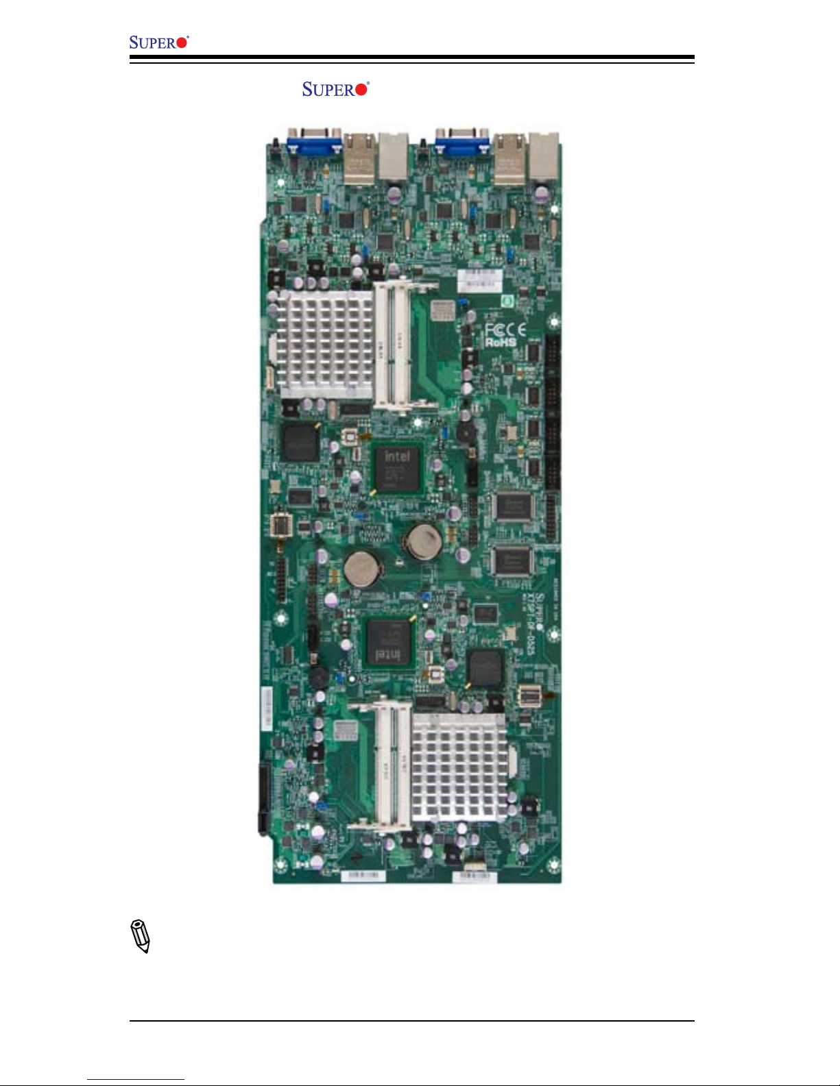
X7SPT-DF-D525 Image
Note: All graphics shown in this manual were based upon the latest PCB Revision
available at the time of publishing of the manual. The motherboard you've received
may or may not look exactly the same as the graphics shown in this manual.
Chapter 1: Introduction
1-3
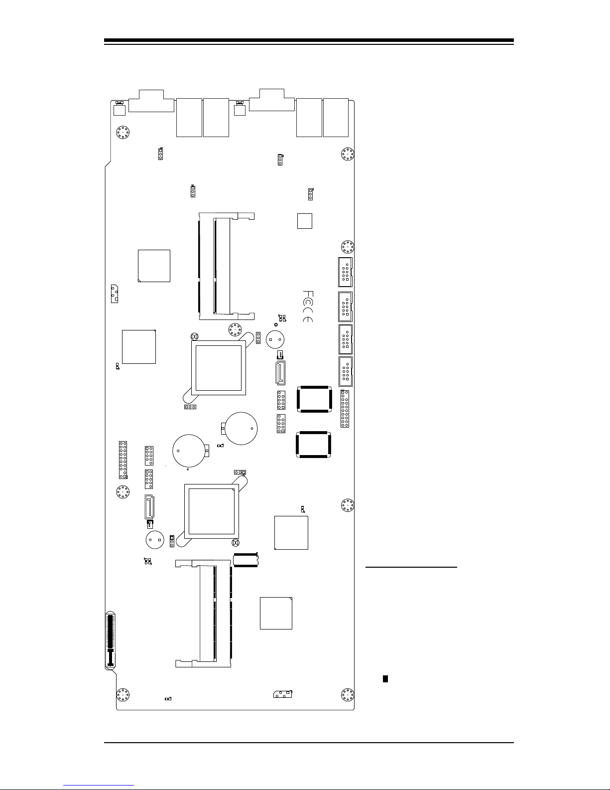
Motherboard Layout
Important Notes
Jumpers not indicated are for •
testing only.
See Chapter 2 for detailed •
information on jumpers, I/O
ports and JF1 front panel
connections.
" " indicates the location of •
"Pin 1".
MH8
MH7MH6
MH5
MH3
MH2
MH1
JKWF1
JWF1
1
3
IKSATA1
ISATA1
BKT1
BT1
LKE2
A
C
LE2
AC
SKW1
SW1
UK67
J666
JKLAN1
JLAN1
JF2
JKTPM
19 20
JTPM
1 2
19 20
JKDIMM1
JDIMM1
JKDIMM2
JDIMM2
E
JKPL2
JKPL1
JKWD1
JKPB
JWD1
JPB
3
JPL1
JPL2
1
U39
DKP3
DKP2
DKP1
A
C
LKE1
A C
LE1
DP2
SKP1
+
SP1
+
JKBT1
JBT1
JKUSB2 JKUSB3
JUSB3
1
7
JUSB2
1
7
JKSMB1
JSMB1
JKCOM1
JKCOM2
JCOM1
JCOM2
5
JVGA1
DP1
1-4
X7SPT-DF-D525 User’s Manual
MH8
MH7MH6
MH5
MH3
MH2
MH1
JKWF1
JWF1
1
3
IKSATA1
ISATA1
BKT1
BT1
LKE2
A
C
LE2
AC
SKW1
SW1
UK67
J666
JKLAN1
JLAN1
JF2
JKTPM
19 20
JTPM
1 2
19 20
JKDIMM1
JDIMM1
JKDIMM2
JDIMM2
E
JKPL2
JKPL1
JKWD1
JKPB
JWD1
JPB
3
JPL1
JPL2
1
U39
DKP3
DKP2
DKP1
A
C
LKE1
A C
LE1
DP2
SKP1
+
SP1
+
JKBT1
JBT1
JKUSB2 JKUSB3
JUSB3
1
7
JUSB2
1
7
JKSMB1
JSMB1
JKCOM1
JKCOM2
JCOM1
JCOM2
5
JVGA1
DP1
9543
10
11
8
7
61 2
12
14
15
16
18
19
23
24
25
26
27
28
29
30
31
45
50
13
32
33
41
42
43
44
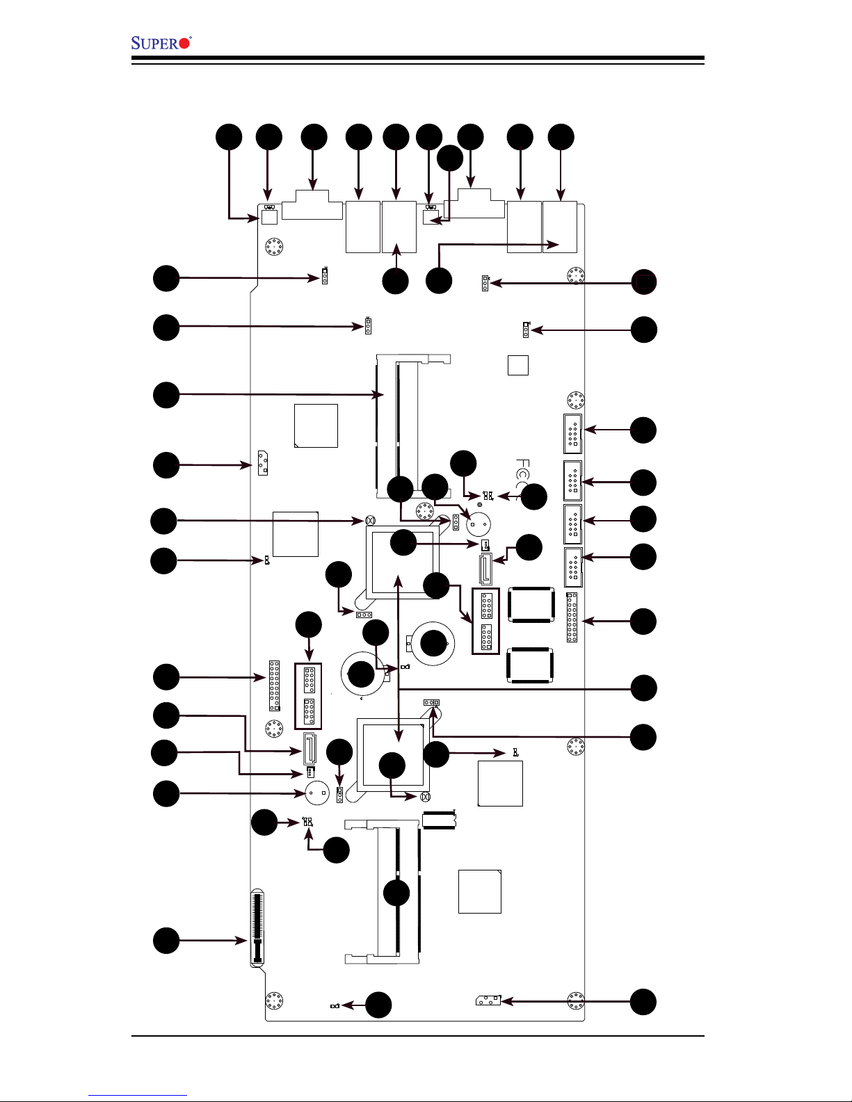
Quick Reference
17
20
21
22
35
36
1
37
1
38
1
39
1
40
47
46
49
48
51
52
34
CPU
Node 2
CPU
Node 1
Chapter 1: Introduction
1-5
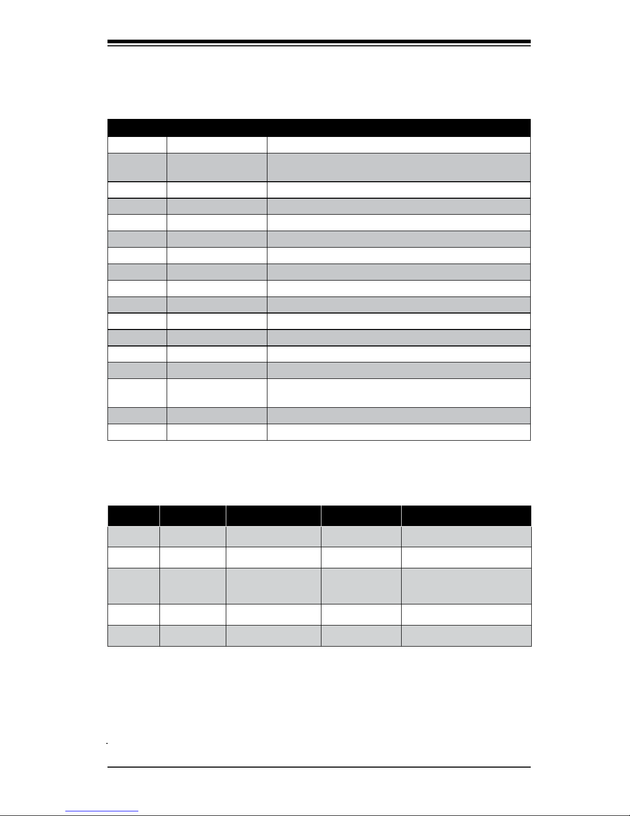
Ports and Connectors
Number Connectors* Description
3,8 JKVGA1, JVGA1 Video/Graphics Connector
4,9
JKLAN1/JKLAN2,
JLAN1/JLAN2
RJ45 Connector for LAN1 and LAN2
5,10 JK666, J666 (top) IPMI Dedicated LAN
13, 22 JCOM2,JKCOM2 Internal Serial Port (COM2)
14, 23 JCOM1,JKCOM1 Internal Serial Port (COM1)
17, 36 SKP1, SP1 Onboard Speaker
24, 39 JKTPM, JTPM TPM Header
25 U1/UK2 ICH9
27, 47 JSMB1, JKSMB1 System Management Bus header
30 JDIMM1, JDIMM2 SO-DIMM Slots (Node 1)
48 JKDIMM1, JKDIMM2 SO-DIMM Slots (Node 2)
29 JF2 Hot Plug Connector
19, 37 JKWF1, JWF1 SATA Disk on Module (DOM) Power
21, 38 IKSATA1, ISATA1 SATA 1 Connector
20, 40
JKUSB2/JKUSB3,
JUSB3/JUSB2
USB Headers
41, 42 BT1,BKT1 Onboard Battery
51, 52 J666, JK666 (bottom) Back Panel USB 2.0 Ports (JUSB0/JUSB1, JKUSB0/JKUSB1)
*NOTE: All jumpers, connectors, LEDs with "K" in the name are for Node 2.
The rest are for Node 1 or shared between the two.
Number LED* Description Color/State Status
2,6 LKE2, LE2 Unit ID LED Blue: Solid On UID On
28, 43 LE1,LKE1 3.3V Dual LED Green: Solid On PWR On
16, 31 DKP2, DP2 Power LED
Green: Solid or
Blinking
Solid On: Power On
Blinking: Suspend
15, 32 DKP3, DP3 SATA LED Green: Blinking SATA Drive Activity
45, 33 DKP1, DP1 BMC Heartbeat LED Green: Blinking BMC is active
LED Indicators
1-6
X7SPT-DF-D525 User’s Manual
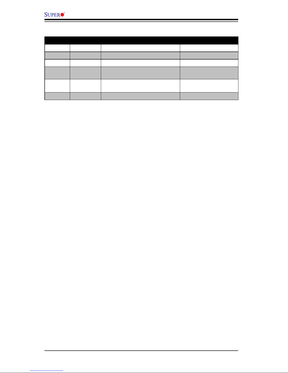
Jumper Descriptions
Number Jumper* Description Default Setting
1,7 SKW1,SW1 Unit ID Switch
Open
11, 50 JPL2, JKPL2 LAN2 Enable/Disable
Pins 1-2 (Enabled)
12, 49 JPL1, JKPL1 LAN1 Enable/Disable
Pins 1-2 (Enabled)
26, 44 JPB,JKPB BMC Enable/Disable
Pins 1-2 (Enabled)
Pins 2-3 (Disabled)
18, 35
JKWD1,
JWD1
Watch Dog Timer Mode
Pins 1-2 (Default)
Pins 2-3 (NMI)
34, 46 JBT1,JKBT1 CMOS Clear
(See Chapter 2)

Chapter 1: Introduction
1-7
Motherboard Features
Special Features
Twin motherboard with two nodes in one board
Processor (Each Node)
Single Integrated Dual-Core Intel® ATOM™ D525 processor, 1.8 GHz, 13 Watts,
2 x 512KB L2 cache
Memory (Each Node)
Supports up to 4GB of unbuffered 800MHz Non-ECC DDR3 SODIMMs in 2 •
sockets (1.5V, 512MB, 1GB, 2GB)
Chipset (Each Node)
Intel® ICH9R (South Bridge)•
Integrated Graphics (Shared)
Matrox G200eW Graphics Accelerator•
BIOS
32 Mb AMI BIOS•
®
, SPI Flash BIOS
PC Health Monitoring
Onboard voltage monitors for CPU Cores, Chipset Voltage, Memory Voltage •
+1.8V, +3.3V, +5V, +12V, +3.3V standby, +5V standby, VBat
Tachometer monitoring •
Status monitor for speed control, on/off control•
Temperature monitor for chassis, CPU environments•
CPU thermal trip support•
Supero Doctor III, Watch Dog/NMI•
PowerConguration
ACPI/ACPM Power Management
•
Keyboard wake-up from soft off•
Fan auto-off in sleep mode•
Power on mode for AC power recovery•

1-8
X7SPT-DF-D525 User’s Manual
I/O Controllers and Ports (Each Node)
Built-in ICH9R SATA Controller •
Winbond Super I/O controller 83627DHG-P •
One back panel VGA port•
1 onboard SATA connector•
3 SATA ports via Hot-Plug slot (Supports RAID 0/1/5/10)•
Dual 10/100/1000 LAN ports (Intel 82574L)•
One IPMI 2.0 with shared LAN ports•
USB 2.0 ports & headers (USB1~USB6): Two ports on the back panel•
One 20-pin TPM Header•
Optimized for the Supermicro 2U chassis.•
12VDC Power through Hot-Plug slot•
OEM Options•
Two Fast 16550-compatible UART COM Ports (internal headers)x
Four USB ports (on two headers)x
Other
Lead free
•
CD Utilities
BIOS ash upgrade utility, Drivers and utilities for Intel® ICH9R chipset
•
Dimensions
6.8" x 16.4"•
Chapter 1: Introduction
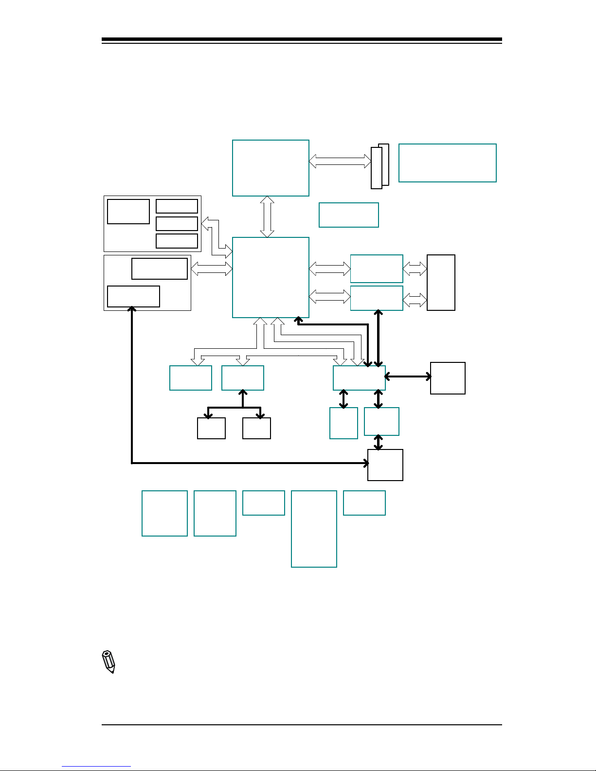
1-9
X7SPT-DF-D525 Series Block Diagram
Note: This is a general block diagram. Please see the Motherboard Features pages
for details on the features of the motherboard.
DC
PINEVIEW-D
SODIMM 1
SODIMM 2
DDR3 800
ICH9R
DMI
Intel 82574L
GbE(LAN2)
Intel 82574L
GbE(LAN1)
PCI-E x1
PCI-E x1
RJ45
Dual
RJ45
USBx2
Combo
MDI
MDI
RMII
X7SPT-DF-D525
LPC
SATA GEN2
x4
USB 2.0 x6
WPCM450
BMC
128MB
DDR2
PCI 33
SDRAM
W83627DHG
SIO
COM 1
Header
COM 2
Header
D525
SATA Port 2
SATA Port 1
SATA Port 3
USB
Header x2
(4 Ports)
USB
Rear
CONN
x2
BLOCK DIAGRAM
12V DC
hot plug connector
UID
FAN PWM control
10/100
Enet
PHY
USBx2
SATA Port 4
DOM
CK505
CLK Generator
USB
x2
TPM
header
VGA
connt.
P5V
VRM
P3V3
VRM
P3V3_DUAL
VRM
P5V_DUAL
V_DIMM
VRM
P1V5
VRM
P1V05
VRM
P1V8PLL
VRM
VCCP
VRM
RMII
Shared LAN
Dedicated LAN

1-10
X7SPT-DF-D525 User’s Manual
1-2 Chipset Overview
I/O Controller Hub: ICH9R
The I/O Controller ICH9R provides the data buffering and interface arbitration re-
quired for the system to operate efciently. It also provides the bandwidth needed
for the system to maintain its peak performance. The Direct Media Interface (DMI)
provides the connection between the MCH and the ICH9R. The ICH9R supports
up to six PCI-Express lanes, six Serial ATA (SATA) ports and twelve USB 2.0 ports.
In addition, the ICH9R offers the Intel Matrix Storage Technology which provides
various RAID options for data protection and rapid data access. It also supports the
next generation of client management through the use of PROActive technology in
conjunction with Intel's next generation Gigabit Ethernet controller.
Intel ICH9R System Features
The I/O Controller Hub provides the I/O subsystem with access to the rest of the
system. Functions and capabilities include:
Advanced Power Management•
SMBus 2.0 (I•
2
C)
SST/PECI Fan Speed Control•
SPI Flash•
Low Pin Count (LPC) Interface •

Chapter 1: Introduction
1-11
1-3 PC Health Monitoring
This section describes the PC health monitoring features of the X7SPT-DF-D525.
The motherboard has an onboard System Hardware Monitor chip that supports PC
health monitoring.
Recovery from AC Power Loss
BIOS provides a setting for you to determine how the system will respond when
AC power is lost and then restored to the system. You can choose for the system
to remain powered off (in which case you must hit the power switch to turn it back
on) or for it to automatically return to a power on state. See the Power Lost Control
setting in the BIOS chapter of this manual to change this setting. The default set-
ting is Last State.
Onboard Voltage Monitoring
The onboard voltage monitor will scan the following voltages continuously: CPU
Cores, Chipset Voltage, Memory Voltage (+1.8V), +3.3V, +3.3V standby, +5V, +12V,
and Vbat. Once a voltage becomes unstable, it will give a warning or send an error
message to the screen. The User can adjust the voltage thresholds to dene the
sensitivity of the voltage monitor by using SD III.
Fan Status Monitor with Software
The PC health monitor can check the RPM status of the cooling fans via Supero
Doctor III.
CPU Overheat LED and Control
This feature is available when the user enables the CPU overheat warning function
in the BIOS. This allows the user to dene an overheat temperature. When this
temperature reaches the pre-dened threshold, the CPU thermal trip feature will be
activated and it will send a signal to the Speaker LED and, at the same time, the
CPU speed will be decreased.

1-12
X7SPT-DF-D525 User’s Manual
1-4 PowerCongurationSettings
This section describes features of your motherboard that deal with power and
power settings.
Slow Blinking LED for Suspend-State Indicator
When the CPU goes into a suspend state, the chassis power LED will start blinking
to indicate that the CPU is in suspend mode. When the user presses any key, the
CPU will wake up and the LED will automatically stop blinking and remain on.
BIOS Support for USB Keyboard
If the USB keyboard is the only keyboard in the system, it will function like a normal
keyboard during system boot-up.
Main Switch Override Mechanism
When an ATX power supply is used, the power button can function as a system
suspend button. When the user presses the power button, the system will enter
a SoftOff state. The monitor will be suspended and the hard drive will spin down.
Pressing the power button again will cause the whole system to wake up. During the
SoftOff state, the ATX power supply provides power to keep the required circuitry
in the system "alive." In case the system malfunctions and you want to turn off the
power, just press and hold the power button for 4 seconds. The power will turn off
and no power will be provided to the motherboard.
1-5 Power Supply
As with all computer products, a stable power source is necessary for proper and
reliable operation. It is even more important for processors that have high CPU
clock rates of 1 GHz and faster.
The X7SPT-DF-D525 accommodates 12V power through its Hot-Plug
port.

Chapter 1: Introduction
1-13
1-6 Super I/O
The Super I/O provides two high-speed, 16550 compatible serial communication
ports (UARTs). Each UART includes a 16-byte send/receive FIFO, a programmable
baud rate generator, complete modem control capability and a processor interrupt
system. Both UARTs provide legacy speed with baud rate of up to 115.2 Kbps as
well as an advanced speed with baud rates of 250 K, 500 K, or 1 Mb/s, which sup-
port higher speed modems.
The Super I/O provides functions that comply with ACPI (Advanced Conguration
and Power Interface), which includes support of legacy and ACPI power manage-
ment through a SMI or SCI function pin. It also features auto power management
to reduce power consumption.
1-7 Overview of the Nuvoton BMC Controller
The NuvotonSM Baseboard Management Controller (BMC), supports the 2D/VGA-
compatible Graphics Core with the PCI interface, Virtual Media, and Keyboard/
Video/Mouse (KVM) Redirection modules.
The Nuvoton BMC interfaces with the host system via a PCI interface to commu-
nicate with the graphics core. It supports USB 2.0 and 1.1 for remote keyboard/
mouse/virtual media emulation. It also provides LPC interface to control Super I/O
functions and is connected to the network via an external Ethernet PHY module. It
also communicates with onboard components via six SMBus interfaces, fan control,
Platform Environment Control Interface (PECI) buses, and General Purpose I/O
(T-SGPIO) ports.
The Nuvoton WPCM450 (Manufacturer P/N WPCM450RA0BX) has all the features
as described above plus IPMI 2.0 support. This particular chip is installed on the
X7SPT-DF-D525 motherboard model.
Note: Please refer to the Embedded IPMI User's Guide posted on our
website at http://www.supermicro.com/support/manuals/. You may also
nd information about IPMI by visiting Intel's website at http://www.intel.
com/design/servers/ipmi/
1-14
X7SPT-DF-D525 User’s Manual
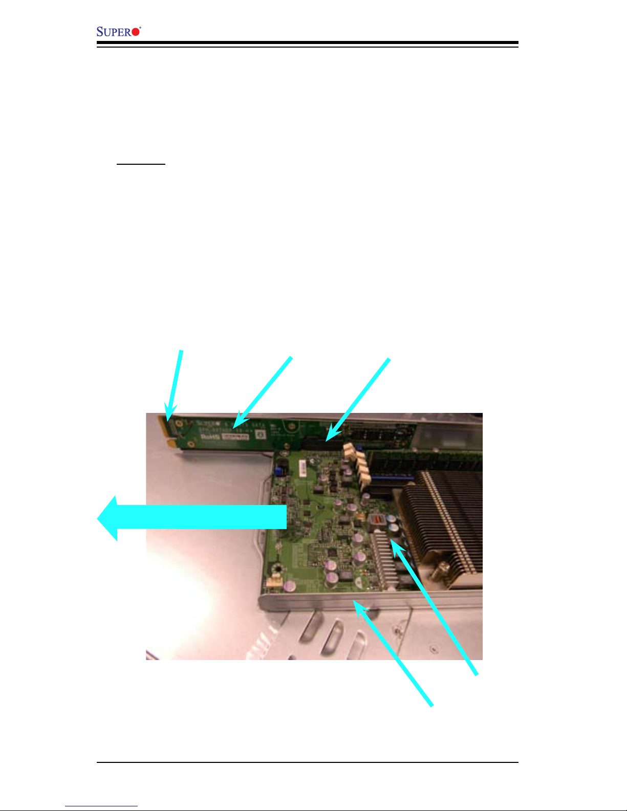
1-8 Node Hot-Swapping
The X7SPT-DF-D525 supports cable-free node hot-swapping when installed in a
Supermicro 2U Twin2 Server chassis together with the cable-free hot-swap adapter
(both sold separately). Node hot-swapping enables the user to replace a mother-
board in a multi-node server without powering down the entire system. However,
cable-free node hot-swapping allows node hot-swapping without the tedious task
of unplugging and plugging back all the supporting cables between the chassis and
motherboard. This is done by mounting the motherboard on a tray and attaching
the tray's adapter to the motherboard. The adapter has a connector on its end
that plugs into the server's backplane. This serves as the connection between the
motherboard and all the components mounted in the chassis. Thus the term 'cable-
free'. It also enables the motherboard to easily slide in and out of the chassis for
easy maintenance. See the gure below for more information.
Ca b l e -F ree No d e
Hot-Swap Adapter.
An Adapter is attached
to the m othe rboa rd.
This connects the SATA
drive, System Power, etc
between the motherboard
and the chassis.
Connector on the
Adapter's end.
The entire module slides into the chassis and the adapter's
connector engages with the socket on the chassis' back-
plane.
Motherboard
The entire setup slides into chassis
Adapter Tray
Note: The image is for illustration purposes only and is not
the same motherboard described in the manual.
 Loading...