

Supermicro SUPERO X10DRD-iTP, SUPERO X10DRD-iNTP, SUPERO X10DRD-LTP User Manual

USER’S MANUAL
Revision 1.0c
X10DRD-LTP
X10DRD-iTP
X10DRD-iNTP

Manual Revision 1.0c
Release Date: Feb. 9, 2015
Unless you request and receive written permission from Super Micro Computer, Inc., you may not
copy any part of this document.
Information in this document is subject to change without notice. Other products and companies
referred to herein are trademarks or registered trademarks of their respective companies or mark
holders.
Copyright © 2015 by Super Micro Computer, Inc.
All rights reserved.
Printed in the United States of America
The information in this User’s Manual has been carefully reviewed and is believed to be accurate.
The vendor assumes no responsibility for any inaccuracies that may be contained in this document
and makes no commitment to update or keep current the information in this manual nor to notify any
person or organization of updates. Please note: For the most up-to-date version of this manual,
please see our website at www.supermicro.com.
Super Micro Computer, Inc. ("Supermicro") reserves the right to make changes to the product
described in this manual at any time and without notice. This product, including software and documentation, is the property of Supermicro and/or its licensors and is supplied only under a license.
Any use or reproduction of this product is not allowed, except as expressly permitted by the terms
of said license.
IN NO EVENT WILL SUPER MICRO COMPUTER, INC. BE LIABLE FOR DIRECT, INDIRECT,
SPECIAL, INCIDENTAL, SPECULATIVE, OR CONSEQUENTIAL DAMAGES ARISING FROM THE
USE OR INABILITY TO USE THIS PRODUCT OR DOCUMENTATION, EVEN IF ADVISED OF THE
POSSIBILITY OF SUCH DAMAGES. IN PARTICULAR, SUPER MICRO COMPUTER, INC. SHALL
NOT BE LIABLE FOR ANY HARDWARE, SOFTWARE, OR DATA STORED OR USED WITH THE
PRODUCT, INCLUDING THE COSTS OF REPAIRING, REPLACING, INTEGRATING, INSTALLING,
OR RECOVERING SUCH HARDWARE, SOFTWARE, OR DATA.
Any disputes arising between the manufacturer and the customer shall be governed by the laws of
Santa Clara County in the State of California, USA. The State of California, County of Santa Clara
shall be the exclusive venue for the resolution of any such disputes. Supermicro's total liability for
all claims will not exceed the price paid for the hardware product.
FCC Statement: This equipment has been tested and found to comply with the limits for a Class
A digital device pursuant to Part 15 of the FCC Rules. These limits are designed to provide
reasonable protection against harmful interference when the equipment is operated in a commercial
environment. This equipment generates, uses, and can radiate radio frequency energy and, if not
installed and used in accordance with the manufacturer’s instruction manual, may cause harmful
interference with radio communications. Operation of this equipment in a residential area is likely
to cause harmful interference, in which case you will be required to correct the interference at your
own expense.
California Best Management Practices Regulations for Perchlorate Materials: This Perchlorate
warning applies only to products containing CR (Manganese Dioxide) Lithium coin cells. “Perchlorate
Material-special handling may apply. See www.dtsc.ca.gov/hazardouswaste/perchlorate.
WARNING: Handling of lead solder materials used in this
product may expose you to lead, a chemical known to
the State of California to cause birth defects and other
reproductive harm.

Preface
This manual is written for system integrators, PC technicians, and
knowledgeable PC users. It provides information for the installation and use of the
X10DRD-iTP/iNTP/LTP motherboard.
About This Motherboard
The Super X10DRD-iTP/iNTP/LTP motherboard supports dual Intel E5-2600 v3
Series processors (Socket R3) that offer new Intel Microarchitecture 22 nm Process
Technology, delivering system performance, power efciency, and feature sets to
address the needs of next-generation data centers. With the PCH C612 built in,
the X10DRD-iTP/iNTP/LTP motherboard supports Intel® Node Manager 3.0, Intel
MCTP Protocol, and Management Engine (ME). This motherboard is ideal for gen-
eral purpose, cloud computing server platforms, optimized for the next-generation
data centers. Please refer to our website (http://www.supermicro.com) for CPU and
memory support updates.
Manual Organization
Chapter 1 describes the features, specications, and performance of the moth-
erboard. It also provides detailed information about the Intel PCH C612 chipset.
Chapter 2 provides hardware installation instructions. Read this chapter when
installing the processor, memory modules, and other hardware components into
the system. If you encounter any problems, see Chapter 3, which describes
troubleshooting procedures for video, memory, and system setup stored in CMOS.
Chapter 4 includes an introduction to BIOS and provides detailed information on
running the BIOS Setup Utility.
Appendix A denes the BIOS error beep codes.
Appendix B lists software installation instructions.
Appendix C contains UEFI BIOS recovery instructions.
Preface
iii

iv
Conventions Used in the Manual
Pay special attention to the following symbols for proper system installation:
Warning: Important information given to ensure proper system installation or to prevent
damage to the components or injury to yourself;
Note: Additional information given to differentiate between models or
instructions provided for proper system setup.
X10DRD-iTP/iNTP/LTP Motherboard User’s Manual

Preface
v
Contacting Supermicro
Headquarters
Address: Super Micro Computer, Inc.
980 Rock Ave.
San Jose, CA 95131 U.S.A.
Tel: +1 (408) 503-8000
Fax: +1 (408) 503-8008
Email: marketing@supermicro.com (General Information)
support@supermicro.com (Technical Support)
Website: www.supermicro.com
Europe
Address: Super Micro Computer B.V.
Het Sterrenbeeld 28, 5215 ML
's-Hertogenbosch, The Netherlands
Tel: +31 (0) 73-6400390
Fax: +31 (0) 73-6416525
Email: sales@supermicro.nl (General Information)
support@supermicro.nl (Technical Support)
rma@supermicro.nl (Customer Support)
Website: www.supermicro.nl
Asia-Pacic
Address: Super Micro Computer, Inc.
3F, No. 150, Jian 1st Rd.
Zhonghe Dist., New Taipei City 235
Taiwan (R.O.C)
Tel: +886-(2) 8226-3990
Fax: +886-(2) 8226-3992
Email: support@supermicro.com.tw
Website: www.supermicro.com.tw

vi
Table of Contents
Preface
Chapter 1 Overview
1-1 Overview ......................................................................................................... 1-1
1-2 Processor and Chipset Overview...................................................................1-11
1-3 Special Features ........................................................................................... 1-12
1-4 System Health Monitoring ............................................................................. 1-12
1-5 ACPI Features ............................................................................................... 1-13
1-6 Power Supply ................................................................................................ 1-13
1-7 Advanced Power Management ..................................................................... 1-14
Intel® Intelligent Power Node Manager (NM) (Available when the Supermicro
Power Manager [SPM] is installed)............................................................... 1-14
Management Engine (ME) ............................................................................ 1-14
Chapter 2 Installation
2-1 Standardized Warning Statements ................................................................. 2-1
Battery Handling .............................................................................................. 2-1
Product Disposal ............................................................................................. 2-3
2-2 Static-Sensitive Devices .................................................................................. 2-4
Precautions ..................................................................................................... 2-4
Unpacking ....................................................................................................... 2-4
2-3 Motherboard Installation .................................................................................. 2-5
Tools Needed .................................................................................................. 2-5
Location of Mounting Holes ............................................................................ 2-5
Installing the Motherboard .............................................................................. 2-6
2-4 Processor and Heatsink Installation................................................................ 2-7
Installing the LGA2011 Processor ................................................................. 2-7
Installing a Passive CPU Heatsink ................................................................2-11
Removing the CPU and the Heatsink ........................................................... 2-12
2-5 Installing and Removing the Memory Modules ............................................. 2-13
Installing & Removing DIMMs ....................................................................... 2-13
Removing Memory Modules ......................................................................... 2-13
2-6 Control Panel Connectors and I/O Ports ...................................................... 2-16
Back Panel Connectors and I/O Ports .......................................................... 2-16
Back Panel I/O Port Locations and Denitions ........................................... 2-16
Serial Ports ............................................................................................... 2-17
Video Connection ..................................................................................... 2-17
Universal Serial Bus (USB) ...................................................................... 2-18
X10DRD-iTP/iNTP/LTP Motherboard User’s Manual

vii
Table of Contents
10G_SPF/Ethernet LAN Ports.................................................................. 2-19
Unit Identier Switches/UID LED Indicators ............................................. 2-20
Front Control Panel ....................................................................................... 2-21
Front Control Panel Pin Denitions............................................................... 2-22
NMI Button ............................................................................................... 2-22
Power LED .............................................................................................. 2-22
HDD/UID LED .......................................................................................... 2-23
NIC1/NIC2 LED Indicators ....................................................................... 2-23
Overheat (OH)/Fan Fail/PWR Fail/UID LED ............................................ 2-24
Power Fail LED ........................................................................................ 2-24
Reset Button ........................................................................................... 2-25
Power Button ........................................................................................... 2-25
2-7 Connecting Cables ........................................................................................ 2-26
Power Connectors ................................................................................... 2-26
Fan Headers ............................................................................................. 2-27
Chassis Intrusion ..................................................................................... 2-27
Internal Speaker ....................................................................................... 2-28
TPM/Port 80 Header ................................................................................ 2-29
NVM Express Connections (For X10DRD-iNTP Only) ............................ 2-29
Power SMB (I2C) Connector .................................................................... 2-30
I-SGPIO 1/2 Headers ............................................................................... 2-31
Standby Power Header ............................................................................ 2-31
2-8 Jumper Settings ............................................................................................ 2-32
Explanation of Jumpers ................................................................................ 2-32
SFP+/LAN 1/2 Enable/Disable ................................................................. 2-32
CMOS Clear ............................................................................................. 2-33
Watch Dog Enable/Disable ...................................................................... 2-33
VGA Enable .............................................................................................. 2-34
BMC Enable ............................................................................................ 2-34
I2C Bus to PCI-Express Slots ................................................................... 2-35
Manufacturer Mode Select ....................................................................... 2-35
2-9 Onboard LED Indicators ............................................................................... 2-36
IPMI-Dedicated LAN LEDs ....................................................................... 2-36
BMC Heartbeat LED ................................................................................ 2-36
SFP+/LAN 1/2 Activity LEDs .................................................................... 2-37
SFP+/LAN 1/2 Heartbeat LEDs ............................................................... 2-37
2-10 SATA 3.0/S-SATA 3.0 Connections ............................................................... 2-38
SATA 3.0 Connections .............................................................................. 2-38
S-SATA 3.0 Connections (For X10DRD-iTP/iNTP Only) ......................... 2-38

viii
Chapter 3 Troubleshooting
3-1 Troubleshooting Procedures ........................................................................... 3-1
3-2 Technical Support Procedures ........................................................................ 3-4
3-3 Battery Removal and Installation .................................................................... 3-6
3-4 Frequently Asked Questions ........................................................................... 3-7
3-5 Returning Merchandise for Service................................................................. 3-8
Chapter 4 BIOS
4-1 Introduction ...................................................................................................... 4-1
4-2 Main Setup ...................................................................................................... 4-2
4-3 Advanced Setup Congurations...................................................................... 4-4
4-4 Event Logs .................................................................................................... 4-29
4-5 IPMI ............................................................................................................... 4-31
4-6 Security Settings ........................................................................................... 4-34
4-7 Boot Settings ................................................................................................. 4-35
4-8 Save & Exit ................................................................................................... 4-38
Appendix A BIOS Error Beep Codes
A-1 BIOS Error Beep Codes .................................................................................A-1
Appendix B Software Installation Instructions
B-1 Installing Software Programs ..........................................................................B-1
B-2 Installing SuperDoctor® 5 ...............................................................................B-2
Appendix C UEFI BIOS Recovery Instructions
C-1 An Overview to the UEFI BIOS ......................................................................C-1
C-2 How to Recover the UEFI BIOS Image (-the Main BIOS Block)....................C-1
C-3 To Recover the Main BIOS Block Using a USB-Attached Device..................C-1
X10DRD-iTP/iNTP/LTP Motherboard User’s Manual

Chapter 1: Overview
1-1
Chapter 1
Overview
1-1 Overview
Checklist
Congratulations on purchasing your computer motherboard from an acknowledged
leader in the industry. Supermicro boards are designed with the utmost care and at-
tention to detail to provide you with the highest standards in quality and performance.
Please check that the following items have all been included with your motherboard.
If anything listed here is damaged or missing, contact your retailer.
The following items are included in the retail box:
•One (1) Supermicro Mainboard
•Four (4) SATA cables (CBL-0044L)
•One (1) iPASS to 4-SATA cable (CBL-0097L-03) (for X10DRD-iTP/iNTP)
•One (1) I/O shield (MCP-260-00042-0N)
•One (1) I/O shield dual-port SFP+ bracket (MCP-260-00087-0N)
• One (1) Quick Reference Guide (MNL-1681-QRG)
Note 1: For your system to work properly, please follow the links below
to download all necessary drivers and utilities and the user's manual for
your motherboard.
•SMCI Product Manuals: http://www.supermicro.com/support/manuals/
•Product Drivers and Utilities: ftp://ftp.supermicro.com/
Note 2: For safety considerations, please refer to the complete list of safety
warnings posted on the Supermicro website at http://www.supermicro.com/
about/policies/safety_information.cfm.
If you have any questions, please contact our support team at support@supermicro.
com.
1-2
X10DRD-iTP/iNTP/LTP Motherboard User’s Manual
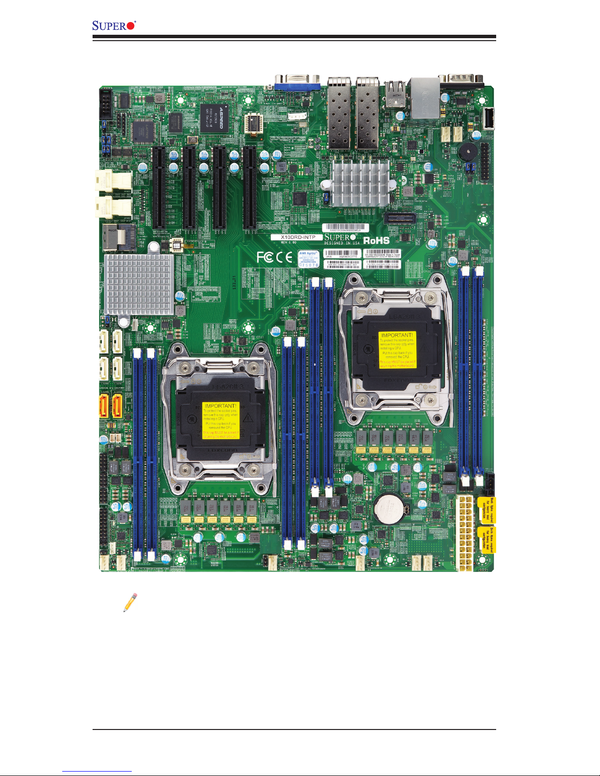
Motherboard Image
Note: All graphics shown in this manual were based upon the latest PCB
revision available at the time of publication of the manual. The mother-
board you received may or may not look exactly the same as the graphics
shown in this manual.
Chapter 1: Overview
1-3
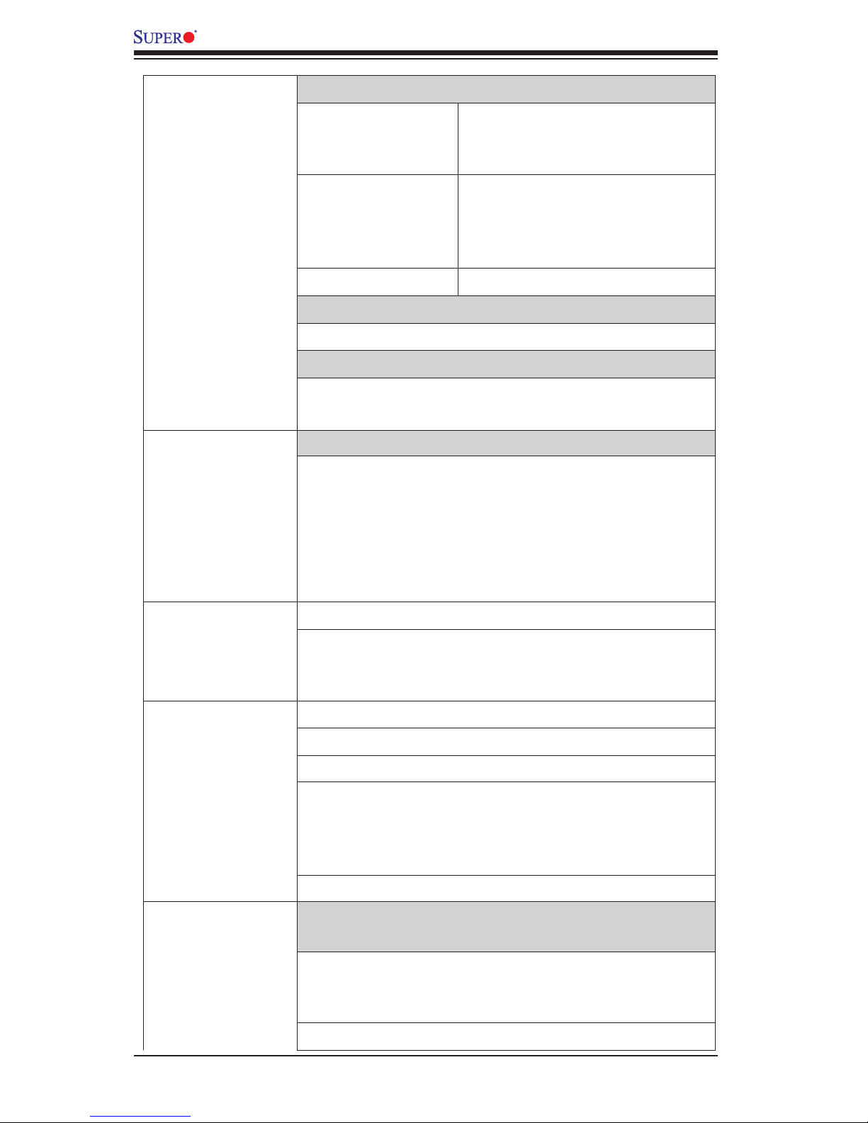
Differences between X10DRD-iTP/-iNTP/-LTP
X10DRD-iTP X10DRD-iNTP X10DRD-LTP
P1-NVME Ports 0/1 No Yes No
CPU1 Slot 4/Slot 5 PCI-E 3.0 x8 (CPU1 required) Yes Yes No
CPU1 Slot 6 PCI-E 3.0 x8 (CPU1 required) Ye s Ye s Yes
CPU2 Slot 7 PCI-E 3.0 x8 (CPU2 required) Ye s Ye s No
S-SATA 0-3 Yes Yes No
iPass Connector Yes Yes No
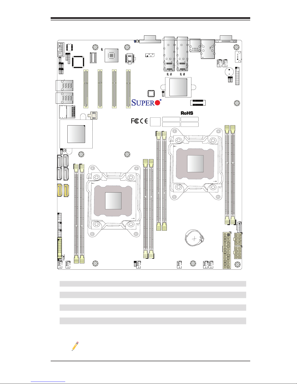
Motherboard Layout
Note: For the latest CPU/Memory updates, please refer to our website at
http://www.supermicro.com/products/motherboard/ for details.
CLOSE 1st
OPEN 1st
SAN MAC
BAR CODE
MAC CODE
IPMI CODE
JBAT1
JUSBRJ45
S-SATA0-3
X10DRD-LTP
REV:1.00
BIOS
LICENSE
I-SATA5
I-SATA4
I-SATA0
I-SATA1
I-SATA3
I-SATA2
JSTBY1
JL1
FAN3
FAN7
FAN8
FAN5
FAN6
I-SGPIO2
I-SGPIO1
JTPM1
JPWR1
JPWR3
JF1
JPI2C1
JPL1
JVRM_I2C2
JVRM_I2C1
JPME2
JI2C2
JWD1
JI2C1
JPG1
LED3
LEDM1
LED1
LED4
LED5
LED6
JUIDB1
SP1
SFP1
SFP2
J1_SFP1
J1_SFP2
CPU1 SLOT4 PCI-E 3.0 X8
P1_NVME0
P1_NVME1
P2-DIMMG1
P2-DIMMH1
P1-DIMMC1
P1-DIMMB1
P1-DIMMD1
P1-DIMMA1
IPMI_LAN
COM1
COM2
USB4/5
CPU1 SLOT5 PCI-E 3.0 X8
CPU1
CPU1 SLOT6 PCI-E 3.0 X8
CPU2 SLOT7 PCI-E 3.0 X8
VGA
LAN1
USB2/3
USB0/1
USB6
JPWR2
LAN2
FAN2
FAN1
FAN4
P2-DIMMF1
P2-DIMME1
JPB1
CPU2
PCH
BMC
AST2400
NIC CTRL
Intel 82599
(For -iTP/iNTP, CPU2 req’ed)
(For -iNTP only)
(For -iTP/iNTP)
BIOS
(For -iTP/iNTP/LTP, CPU1 req’ed)
(For -iTP/iNTP, CPU1 req’ed)
(For -iTP/iNTP, CPU1 req’ed)
CLOSE 1st
OPEN 1st
JIPMB1
1-4
X10DRD-iTP/iNTP/LTP Motherboard User’s Manual
Notes:
•See Chapter 2 for detailed information on jumpers, I/O ports, and JF1 front
panel connections.
• indicates the location of Pin 1.
•Jumpers/LED indicators not indicated are used for testing only.
•Please refer to the table on Page 1-3 to see model variations.
•Use only the correct type of onboard CMOS battery as specied by the manufac-
turer. Do not install the onboard battery upside down to avoid possible explosion.
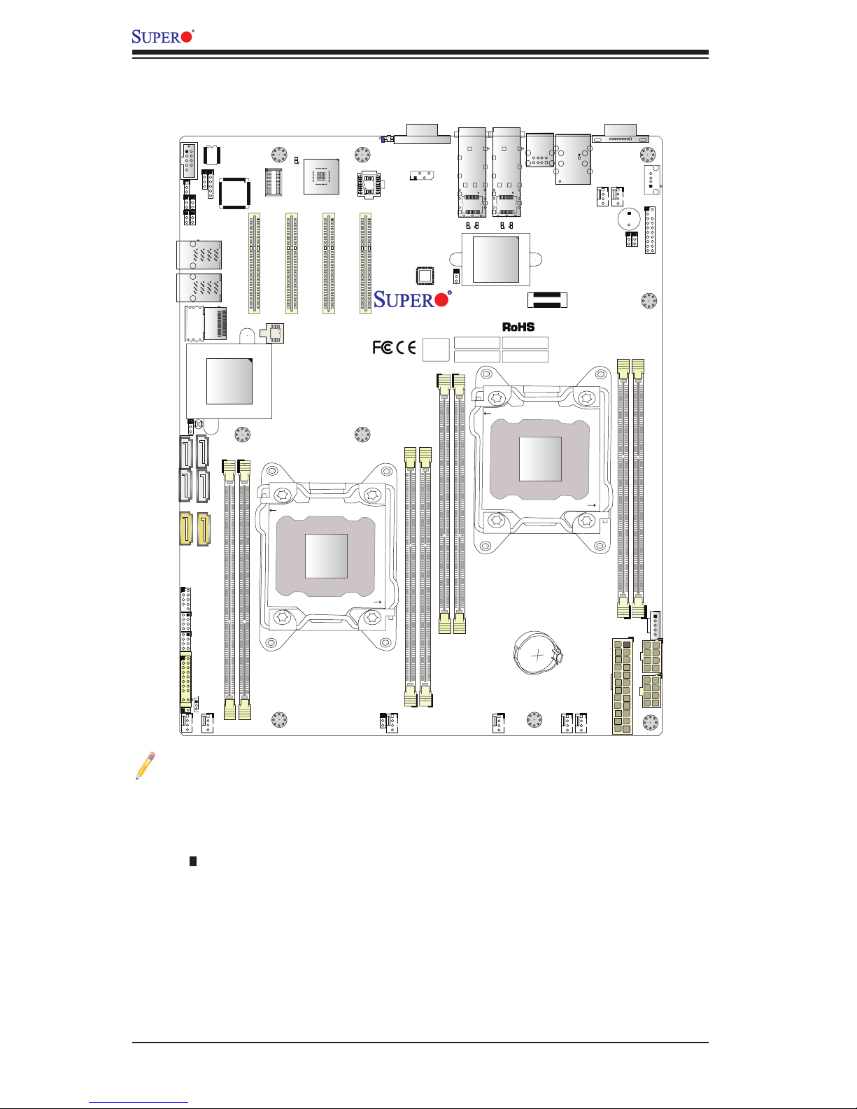
X10DRD-iTP/iNTP/LTP Quick Reference
CLOSE 1st
OPEN 1st
SAN MAC
BAR CODE
MAC CODE
IPMI CODE
JBAT1
JUSBRJ45
S-SATA0-3
X10DRD-LTP
REV:1.00
BIOS
LICENSE
I-SATA5
I-SATA4
I-SATA0
I-SATA1
I-SATA3
I-SATA2
JSTBY1
JL1
FAN3
FAN7
FAN8
FAN5
FAN6
I-SGPIO2
I-SGPIO1
JTPM1
JPWR1
JPWR3
JF1
JPI2C1
JPL1
JVRM_I2C2
JVRM_I2C1
JPME2
JI2C2
JWD1
JI2C1
JPG1
LED3
LEDM1
LED1
LED4
LED5
LED6
JUIDB1
SP1
SFP1
SFP2
J1_SFP1
J1_SFP2
CPU1 SLOT4 PCI-E 3.0 X8
P1_NVME0
P1_NVME1
P2-DIMMG1
P2-DIMMH1
P1-DIMMC1
P1-DIMMB1
P1-DIMMD1
P1-DIMMA1
IPMI_LAN
COM1
COM2
USB4/5
CPU1 SLOT5 PCI-E 3.0 X8
CPU1
CPU1 SLOT6 PCI-E 3.0 X8
CPU2 SLOT7 PCI-E 3.0 X8
VGA
LAN1
USB2/3
USB0/1
USB6
JPWR2
LAN2
FAN2
FAN1
FAN4
P2-DIMMF1
P2-DIMME1
JPB1
CPU2
PCH
BMC
AST2400
NIC CTRL
Intel 82599
(For -iTP/iNTP, CPU2 req’ed)
(For -iNTP only)
(For -iTP/iNTP)
BIOS
(For -iTP/iNTP/LTP, CPU1 req’ed)
(For -iTP/iNTP, CPU1 req’ed)
(For -iTP/iNTP, CPU1 req’ed)
CLOSE 1st
OPEN 1st
JIPMB1

Chapter 1: Overview
1-5
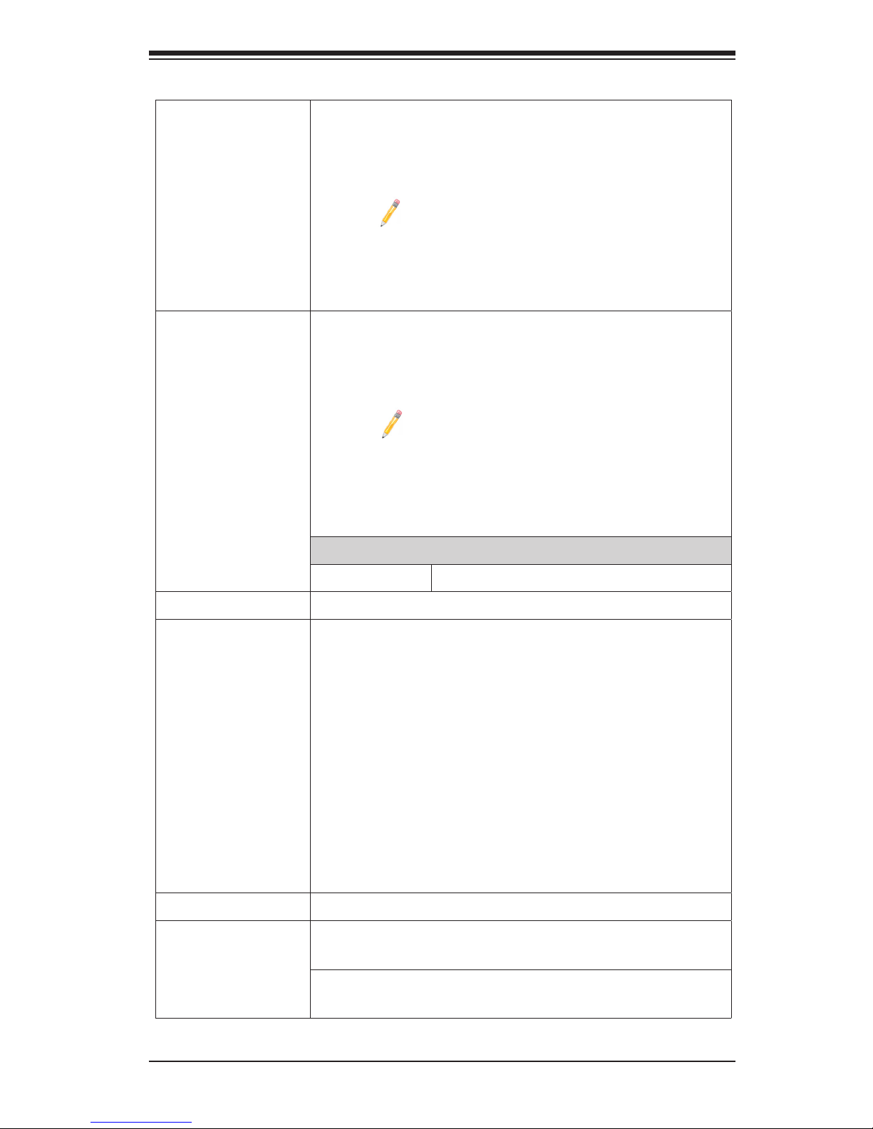
Jumper Description Default Setting
JBT1 Clear CMOS/Reset BIOS Conguration See Chapter 2
JI2C1/JI2C2 SMB to PCI-E Slots Pins 2-3 (Disabled)
JPB1
BMC Enable Pins 1-2 (Enabled)
JPG1
VGA Enable Pins 1-2 (Enabled)
JPL1 10G_SPF/LAN 1/2 Enable Pins 1-2 (Enabled)
JPME2 Manufacture (ME) Mode Select Pins 1-2 (Normal)
JWD1 Watch Dog Timer Enable Pins 1-2 (Reset)
Connectors Description
JBAT1 (Battery) Onboard CMOS battery (See Chpt. 3 for Used Battery Dis-
posal)
COM1/COM2 Backplane COM Port1/Front accessible COM2 header
FAN 1- 8 CPU/system fan headers (FAN1-FAN8)
IPMI_LAN IPMI_dedicated LAN support by the Aspeed controller
JF1 Front panel control header
JL1 Chassis intrusion header
JPI2C1 Power supply SMBbus I2C header
JPWR1 24-pin ATX main power connector (See Warning on Pg. 1-6)
JPWR2/JPWR3 12V 8-pin power connectors (See Warning on Pg. 1-6.)
JSTBY1 Standby power connector
JTPM1 TPM (Trusted Platform Module)/Port 80 header
P1-NVME0/1 NVM Express PCI-E 3.0 x4 ports supported by CPU1 (for
X10DRD-iNTP only)
I-SATA 0-5 SATA 3.0 connectors supported by Intel PCH (I-SATA 0-5),
(I-SATA4/I-SATA5: can be used as Supermicro SuperDOMs
[Devices-on-Module] with built-in power connectors)
I-SGPIO1/2 Seria_Link General Purpose I/O headers 1/2 for SATA ports
(I-SGPIO1 for I-SATA0-3, I-SGPIO2 for I-SATA4/5)
S-SATA0-3 SATA 3.0 connections 0-3 supported by Intel SCU (for
X10DRD-iTP/iNTP only)
SFP+/LAN1 10G_SFP+ (Small-form Factor Pluggable) Ethernet LAN Port
1 (J1_SFP1)
SFP+/LAN2 10G_SFP+ (Small-form Factor Pluggable) Ethernet LAN Port
2 (J1_SFP2)
(CPU1)Slot4 PCI-Express 3.0 x8 slot from CPU1 (for X10DRD-iTP/iNTP)
(CPU1)Slot5 PCI-Express 3.0 x8 slot from CPU1 (for X10DRD-iTP/iNTP)
(CPU1)Slot6 PCI-Express 3.0 x8 slot from CPU1 (for X10DRD-iTP/iNTP/
LTP)
(CPU2)Slot7 PCI-Express 3.0 x8 slot from CPU2 (CPU2 is required) (for
X10DRD-iTP/iNTP)

1-6
X10DRD-iTP/iNTP/LTP Motherboard User’s Manual
Warning!
To avoid damaging the power supply or the motherboard, please use a power supply
that contains a 24-pin, and two 8-pin power connectors, and connect the power supply
to the 24-pin power connector located at JPWR1, and the two 8-pin power connectors
located at JPWR2 and JPWR3. Failure to do so may void the manufacturer warranty
on your power supply and motherboard.
SP1 Internal speaker/buzzer
UID-SW (JUIDB1) UID (Unit Identication) switch
(BP) USB 0/1 (2.0) Backpanel USB 2.0 ports 0/1
(BP) USB 2/3 (2.0) Front accessible USB 2.0 connections (USB 2/3) header
(BP) USB 4/5 (2.0) Backpanel USB 2.0 ports 4/5
(FP) USB 6 (2.0) Front accessible Type A 2.0 connector (USB6)
VGA Backpanel VGA port
LED Description State Status
LED1 Rear UID LED Blue: On Unit Identied
LED3 SFP+/LAN1 Activity LED Green: Blinking SFP+/LAN1 Active
LED4 SFP+/LAN1 Heartbeat LED Green: Blinking SFP+/LAN1 Normal
LED5 SFP+/LAN2 Activity LED Green: Blinking SFP+/LAN2 Active
LED6 SFP+/LAN1 Heartbeat LED Green: Blinking SFP+/LAN2 Normal
LEDM1 BMC Heartbeat LED Green: Blinking BMC Normal
Chapter 1: Overview
1-7
Motherboard Features
CPU
• Dual Intel
®
E5-2600 v3 Series processors (Socket
R3-LGA 2011); each processor supports dual full-
width Intel QuickPath Interconnect (QPI) links (of up
to 9.6 GT/s one direction per QPI)
Note: Please install both CPUs for full access
to the PCI-E slots, DIMM slots, and onboard
controllers. Refer to the block diagram on page
1-10 to determine which slots or devices may
be affected. Please populate CPU socket 1 rst.
Memory
• Integrated memory controller supports up to 512 GB
of Load Reduced (LRDIMM) or 256 GB of Registered
(RDIMM) DDR4 (288-pin) ECC 2133/1866/1600 MHz
modules in eight slots
Note 1: Memory speed support depends on the
processors used in the system.
Note 2: For the latest CPU/memory updates,
please refer to our website at http://www.super-
micro.com/products/motherboard.
DIMM Sizes
• DIMM Up to 64GB @ 1.2V
Chipset
• Intel® PCH C612
Expansion
• Four (4) PCI Express 3.0 x8 slots
•CPU1 Slot 4/Slot 5 (CPU1 required, X10DRD-
iTP/iNTP only),
•CPU1 Slot 6 (CPU1 required, X10DRD-iTP/
iNTP/LTP),
•CPU2 Slot 7 (CPU2 required, X10DRD-iTP/
iNTP only)
• Two (2) NVMe Ports 1/2 (dual PCI-E x4 via internal
mini-SAS HD connectors) (For X10DRD-iNTP only)
Slots
Graphics
• Graphics controller via Aspeed 2400 BMC
Network
• Intel 82599ES supports dual 10G SFP+ dual 10G-
LANs with NC-SI function (SFP+/LAN 1/2)
• Aspeed AST 2400 Baseboard Controller (BMC) sup-
ports IPMI 2.0
1-8
X10DRD-iTP/iNTP/LTP Motherboard User’s Manual
I/O Devices
SATA Connections
• SATA 3.0 Six (6) SATA 3.0 ports supported
by Intel PCH (I-SATA 0-5, I-SATA
4/5 supports SuperDOMs)
• S-SATA 3.0 One (1) SATA 3.0 w/ 4 connec-
tions supported by the SCU
(S-SATA 0-3) for X10DRD-iTP/
iNTP only
• RAID (PCH) RAID 0, 1, 10, 5
IPMI 2.0
• IPMI 2.0 supported by Aspeed AST 2400
Serial (COM) Port
• One (1) Fast UART 16550 port on the I/O back panel
• One (1) serial-port header
Peripheral
Devices
USB Devices
• Four (4) USB 2.0 ports on the rear I/O panel (USB
0/1, 2/3),
• One (1) USB 2.0 header provides two USB connec-
tions (USB 4/5),
• One (1) USB 2.0 Type A connector for front access
(USB 6)
BIOS
• 16 MB SPI AMI BIOS
®
SM Flash UEFI BIOS
• ACPI 2.0/3.0/4.0, USB keyboard, Plug-and-Play
(PnP), SPI dual/quad speed support, RTC (Real-
Time Clock) Wake-Up, and SMBIOS 2.7 or later
Power
• ACPI Power Management
Management
• Main switch override mechanism
• Power-on mode for AC power recovery
• Intel
®
Intelligent Power Node Manager 3.0 (available
when the Supermicro Power Manager [SPM] is in-
stalled and a special power supply is used. See the
note on Page 1-14.)
• Management Engine (ME)
System
Health
System Health/CPU Monitoring
Monitoring
• Onboard voltage monitoring for 1.2V +3.3V, 3.3V
standby, +5V, +5V standby, +12V, CPU core, mem-
ory, chipset, BMC, PCH, and battery voltages
• CPU/system overheat LED and control
Chapter 1: Overview
1-9
• CPU Thermal Trip support
• Status monitor for speed control
• Status monitor for on/off control
• CPU Thermal Design Power (TDP) support of up to
145W (See Note 1 on page 1-9.)
Fan Control
• Fan status monitoring via IPMI connections
• Single cooling zone
• Low-noise fan speed control
• Pulse Width Modulation (PWM) fan control
System
Management
• PECI (Platform Environment Control Interface) 2.0
support
• UID (Unit Identication)/Remote UID
• System resource alert via SuperDoctor 5
• SuperDoctor® 5, Watch Dog, NMI
• Chassis intrusion header and detection
Dimensions
• 13.05" (L) x 10.50" (W) (331.47 mm x 266.70 mm)
Note 1: The CPU maximum thermal design power (TDP) is subject to
chassis and heatsink cooling restrictions. For proper thermal management,
please check the chassis and heatsink specications for proper CPU TDP
sizing.
Note 2: For IPMI conguration instructions, please refer to the Embedded
IPMI Conguration User's Guide available @ http://www.supermicro.com/
support/manuals/.
Note 3: It is strongly recommended that you change BMC log-in informa-
tion upon initial system power-on. The manufacture default username is
ADMIN and the password is ADMIN. For proper BMC conguration, please
refer to http://www.supermicro.com/products/info/les/IPMI/Best_Practices_
BMC_Security.pdf
1-10
X10DRD-iTP/iNTP/LTP Motherboard User’s Manual
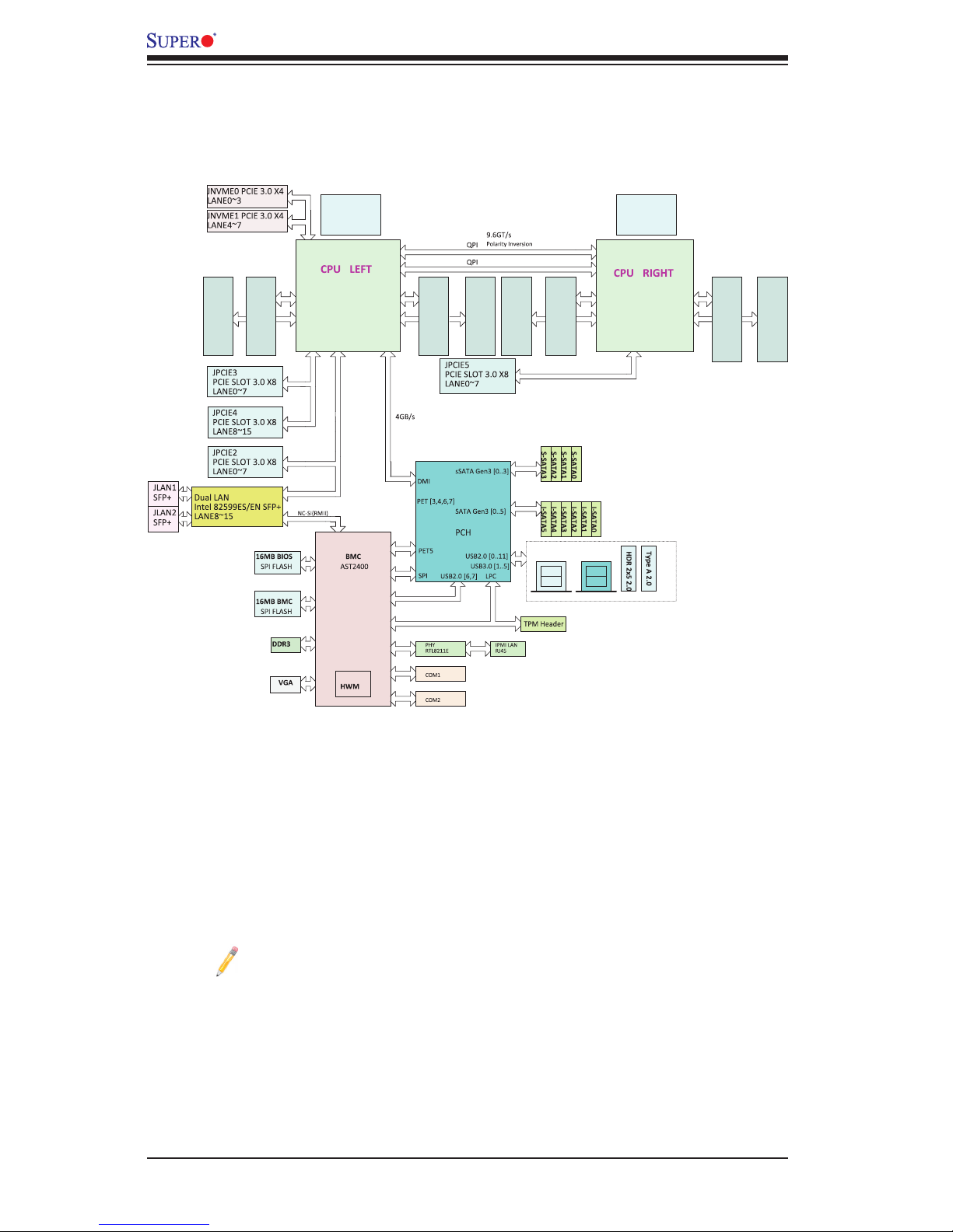
System Block Diagram
Note 1: This is a general block diagram and may not exactly represent
the features on your motherboard. See the Motherboard Features pages
for the actual specications of each motherboard.
Note 2: Both CPUs need to be installed for full access to the PCI-E slots,
DIMM slots, and onboard controllers. Refer to the block diagram above to
determine which slots or devices may be affected. Please always populate
CPU socket 1 rst.
X10DRD-i(N)TP/LTP
6 PHAS E
145W
VR12.5
VCCP1 12v
x8
P1
P1
P0
P0
DMIPE1PE2PE3PE3 DMI
PE1
PE2
DDR4 DIMM
4,5
port 0,1
REAR 2.0
DDR4 DIMM
#1
DDR4 DIMM
EA
x8
PROCESSOR
1
DDR4 DIMM#1DDR4 DIMM
DDR4 DIMM
2,3
REAR 2.0
DDR4 DIMM
F
DDR4 DIMM
G
H
C
#1 #1 #1 #1#1 #1
6 PHASE
145W
VR12.5
VCCP0 12v
8
x8
x8
x4
x8
B
D
PROCESSOR
2
x4

Chapter 1: Overview
1-11
1-2 Processor and Chipset Overview
Built upon the functionality and capability of the Intel E5-2600 v3 Series proces-
sors (Socket R3) and the Intel C612 PCH, the X10DRD-iTP/iNTP/LTP motherboard
provides system performance, power efciency, and feature sets to address the
needs of next-generation computer users. This motherboard is ideal for general
purpose, cloud computing, and datacenter-optimized server platforms.
With support of the new Intel microarchitecture 22 nm process technology, the
X10DRD-iTP/iNTP/LTP drastically increases system performance for a multitude
of server applications.
The PCH C612 chip provides Enterprise SMbus support, including the following
features:
•DDR4 288-pin memory support on Socket R3
•Support for MCTP Protocol
•Support for Management Engine (ME)
•Support of SMBus speeds of up to 400KHz for BMC connectivity
•Improved I/O capabilities to high-storage-capacity congurations
•SPI enhancements
•Intel® Node Manager 3.0 for advanced power monitoring, capping, and man-
agement for BMC enhancement
•The BMC supports remote management, virtualization, and the security pack-
age for enterprise platforms
Note: Node Manager 3.0 support is dependent on the power supply used
in the system.

1-12
X10DRD-iTP/iNTP/LTP Motherboard User’s Manual
1-3 Special Features
Recovery from AC Power Loss
The Basic I/O System (BIOS) provides a setting that determines how the system will
respond when AC power is lost and then restored to the system. You can choose
for the system to remain powered off (in which case you must press the power
switch to turn it back on) or for it to automatically return to the power-on state. See
the Advanced BIOS Setup section for this setting. The default setting is Last State.
1-4 System Health Monitoring
This section describes the features of system health monitoring of the motherboard.
This motherboard has an onboard Baseboard Management Controller (BMC) that
supports system health monitoring. An onboard voltage monitor will scan the follow-
ing onboard voltages continuously: 1.2V, +3.3V, 3.3V standby, +5V, +5V standby,
+12V, CPU core, memory, chipset, BMC, PCH, and battery voltages. Once a voltage
becomes unstable, a warning is given or an error message is sent to the screen. The
user can adjust the voltage thresholds to dene the sensitivity of the voltage monitor.
Fan Status Monitor with Firmware Control
System health monitoring support provided by the BMC controller can check the
RPM status of a cooling fan. The onboard CPU and chassis fans are controlled by
IPMI Thermal Management.
Environmental Temperature Control
System health sensors in the BMC monitors temperatures and voltage settings of
onboard processors and the system in real time via the IPMI interface. Whenever
the temperature of the CPU or the system exceeds a user-dened threshold, system/
CPU cooling fans will be turned on to prevent the CPU or system from overheating.
Note: To avoid possible system overheating, please be sure to provide
adequate airow to your system.
System Resource Alert
This feature is available when used with SuperDoctor 5. SuperDoctor 5 is used
to notify the user of certain system events. For example, you can congure
SuperDoctor 5 to warn you when the system temperature, CPU temperatures,
voltages, or fan speeds go beyond a predened range.

Chapter 1: Overview
1-13
1-5 ACPI Features
ACPI stands for Advanced Conguration and Power Interface. The ACPI speci-
cation denes a exible and abstract hardware interface that provides a standard
way to integrate power management features throughout a system, including its
hardware, operating system, and application software. This enables the system to
automatically turn on and off peripherals such as network cards, hard-disk drives,
and printers.
In addition to power management directed by the operating system, the ACPI also
provides a generic system event mechanism for Plug-and-Play and an interface
(independent of the operating system) for conguration control. ACPI leverages
the Plug-and-Play BIOS data structures, while providing an implementation that is
independent of the processor architecture and compatible with Windows 8/R2 and
Windows 2012/R2 Operating Systems.
1-6 Power Supply
As with all computer products, a stable power source is necessary for proper and
reliable operation. This is even more important for processors that have high CPU
clock rates.
The X10DRD-iTP/iNTP/LTP motherboard accommodates 24-pin ATX power sup-
plies. Although most power supplies generally meet the specications required by
the CPU, some are inadequate. In addition, two 12V 8-pin power connectors are
also required to ensure adequate power supply to the system.
Warning!
To avoid damaging the power supply or the motherboard, please use a power supply
that contains a 24-pin, and two 8-pin power connectors, and connect the power supply
to the 24-pin power connector located at JPWR1, and the two 8-pin power connectors
located at JPWR2 and JPWR3. Failure to do so may void the manufacturer warranty
on your power supply and motherboard.
It is strongly recommended that you use a high-quality power supply that meets
the ATX power supply specication 2.02 or above. It must also be SSI-compliant.
(For more information, please refer to the website at http://www.ssiforum.org/.) Ad-
ditionally, in areas where noisy power transmission is present, you may choose to
install a line lter to shield the computer from noise. It is recommended that you
also install a power surge protector to help avoid problems caused by power surges.

1-14
X10DRD-iTP/iNTP/LTP Motherboard User’s Manual
1-7 Advanced Power Management
The following new advanced power management features are supported by this
motherboard:
Intel® Intelligent Power Node Manager (NM) (Available
when the Supermicro Power Manager [SPM] is installed)
The Intel® Intelligent Power Node Manager 3.0 (IPNM) provides your system with
real-time thermal control and power management for maximum energy efciency.
Although IPNM Specication Version 2.0/3.0 is supported by the BMC (Baseboard
Management Controller), your system must also have IPNM-compatible Manage-
ment Engine (ME) rmware installed to use this feature.
Note: Support for IPNM Specication Version 2.0 or Version 3.0 is depen-
dent on the power supply used in the system.
Management Engine (ME)
The Management Engine, which is an ARC controller embedded in the PCH, pro-
vides Server Platform Services (SPS) to your system. The services provided by
SPS are different from those provided by the ME on client platforms.
Chapter 2: Installation
2-1
Chapter 2
Installation
2-1 Standardized Warning Statements
The following statements are industry-standard warnings, provided to warn the user
of situations which have the potential for bodily injury. Should you have questions or
experience difculty, contact Supermicro's Technical Support Department for assis-
tance. Only certied technicians should attempt to install or congure components.
Read this section in its entirety before installing or conguring components in the
Supermicro chassis.
Battery Handling
Warnung
Bei Einsetzen einer falschen Batterie besteht Explosionsgefahr. Ersetzen Sie die
Batterie nur durch den gleichen oder vom Hersteller empfohlenen Batterietyp.
Entsorgen Sie die benutzten Batterien nach den Anweisungen des Herstellers.
Warning!
There is a danger of explosion if the battery is replaced incorrectly. Replace the
battery only with the same or an equivalent type recommended by the manufacturer.
Dispose of used batteries according to the manufacturer's instructions.
電池の取り扱い
電池交換が正しく行われなかった場合、破裂の危険性があります。 交換する電池はメー
カーが推奨する型、または同等のものを使用下さい。 使用済電池は製造元の指示に従
って処分して下さい。
警告
电池更换不当会有爆炸危险。请只使用同类电池或制造商推荐的功能相当的电池更
换原有电池。请按制造商的说明处理废旧电池。
警告
電池更換不當會有爆炸危險。請使用製造商建議之相同或功能相當的電池更換原有
電池。請按照製造商的說明指示處理廢棄舊電池。

2-2
X10DRD-iTP/iNTP/LTP Motherboard User’s Manual
Attention
Danger d'explosion si la pile n'est pas remplacée correctement. Ne la remplacer
que par une pile de type semblable ou équivalent, recommandée par le fabricant.
Jeter les piles usagées conformément aux instructions du fabricant.
¡Advertencia!
Existe peligro de explosión si la batería se reemplaza de manera incorrecta. Re-
emplazar la batería exclusivamente con el mismo tipo o el equivalente recomen-
dado por el fabricante. Desechar las baterías gastadas según las instrucciones
del fabricante.
!הרהזא
תנכס תמייקץוציפ .הניקת אל ךרדב הפלחוהו הדימב הללוסה לש ףילחהל שי
גוסב הללוסה תא מ םאותה תרבחלמומ ןרציתצ.
תוללוסה קוליס תושמושמה עצבל שי .ןרציה תוארוה יפל
경고!
배터리가 올바르게 교체되지 않으면 폭발의 위험이 있습니다. 기존 배터리와 동일
하거나 제조사에서 권장하는 동등한 종류의 배터리로만 교체해야 합니다. 제조사
의 안내에 따라 사용된 배터리를 처리하여 주십시오.
Waarschuwing
Er is ontplofngsgevaar indien de batterij verkeerd vervangen wordt. Vervang de
batterij slechts met hetzelfde of een equivalent type die door de fabrikant aan-
bevolen wordt. Gebruikte batterijen dienen overeenkomstig fabrieksvoorschriften
afgevoerd te worden.

Chapter 2: Installation
2-3
Product Disposal
Warning!
Ultimate disposal of this product should be handled according to all national laws
and regulations.
製品の廃棄
この製品を廃棄処分する場合、国の関係する全ての法律・条例に従い処理する必要が
ありま す 。
警告
本产品的废弃处理应根据所有国家的法律和规章进行。
警告
本產品的廢棄處理應根據所有國家的法律和規章進行。
Warnung
Die Entsorgung dieses Produkts sollte gemäß allen Bestimmungen und Gesetzen
des Landes erfolgen.
¡Advertencia!
Al deshacerse por completo de este producto debe seguir todas las leyes y regla-
mentos nacionales.
Attention
La mise au rebut ou le recyclage de ce produit sont généralement soumis à des
lois et/ou directives de respect de l'environnement. Renseignez-vous auprès de
l'organisme compétent.
רצומה קוליס
!הרהזא
ו תויחנהל םאתהב תויהל בייח הז רצומ לש יפוס קוליס.הנידמה יקוח

2-4
X10DRD-iTP/iNTP/LTP Motherboard User’s Manual
2-2 Static-Sensitive Devices
Electrostatic Discharge (ESD) can damage electronic com ponents. To avoid dam-
aging your system board, it is important to handle it very carefully. The following
measures are generally sufcient to protect your equipment from ESD.
Precautions
•Use a grounded wrist strap designed to prevent static discharge.
•Touch a grounded metal object before removing the board from the antistatic
bag.
•Handle the motherboard by its edges only; do not touch its components, periph-
eral chips, memory modules, or gold contacts.
•When handling chips or modules, avoid touching their pins.
•Put the motherboard and peripherals back into their antistatic bags when not
in use.
•For grounding purposes, make sure that your system chassis provides excel-
lent conductivity between the power supply, case, mounting fasteners, and the
motherboard.
Unpacking
The motherboard is shipped in antistatic packaging to avoid static damage. When
unpacking the motherboard, make sure that the person handling it is static-
protected.
Waarschuwing
De uiteindelijke verwijdering van dit product dient te geschieden in overeenstemming
met alle nationale wetten en reglementen.
경고!
이 제품은 해당 국가의 관련 법규 및 규정에 따라 폐기되어야 합니다.
Chapter 2: Installation
2-5
CLOSE 1st
OPEN 1st
SAN MAC
BAR CODE
MAC CODE
IPMI CODE
JBAT1
JUSBRJ45
S-SATA0-3
X10DRD-LTP
REV:1.00
BIOS
LICENSE
I-SATA5
I-SATA4
I-SATA0
I-SATA1
I-SATA3
I-SATA2
JSTBY1
JL1
FAN3
FAN7
FAN8
FAN5
FAN6
I-SGPIO2
I-SGPIO1
JTPM1
JPWR1
JPWR3
JF1
JPI2C1
JPL1
JVRM_I2C2
JVRM_I2C1
JPME2
JI2C2
JWD1
JI2C1
JPG1
LED3
LEDM1
LED1
LED4
LED5
LED6
JUIDB1
SP1
SFP1
SFP2
J1_SFP1
J1_SFP2
CPU1 SLOT4 PCI-E 3.0 X8
P1_NVME0
P1_NVME1
P2-DIMMG1
P2-DIMMH1
P1-DIMMC1
P1-DIMMB1
P1-DIMMD1
P1-DIMMA1
IPMI_LAN
COM1
COM2
USB4/5
CPU1 SLOT5 PCI-E 3.0 X8
CPU1
CPU1 SLOT6 PCI-E 3.0 X8
CPU2 SLOT7 PCI-E 3.0 X8
VGA
LAN1
USB2/3
USB0/1
USB6
JPWR2
LAN2
FAN2
FAN1
FAN4
P2-DIMMF1
P2-DIMME1
JPB1
CPU2
PCH
BMC
AST2400
NIC CTRL
Intel 82599
(For -iTP/iNTP, CPU2 req’ed)
(For -iNTP only)
(For -iTP/iNTP)
BIOS
(For -iTP/iNTP/LTP, CPU1 req’ed)
(For -iTP/iNTP, CPU1 req’ed)
(For -iTP/iNTP, CPU1 req’ed)
CLOSE 1st
OPEN 1st
JIPMB1
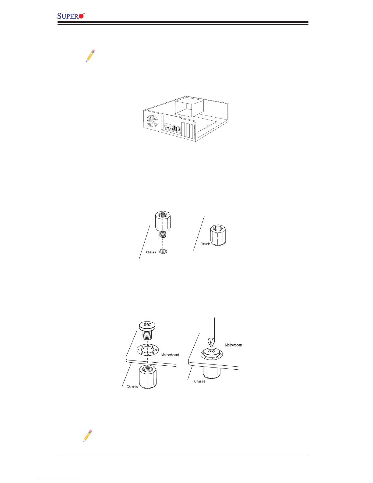
2-3 Motherboard Installation
All motherboards have standard mounting holes to t different types of chassis.
Make sure that the locations of all mounting holes for both motherboard and chassis
match. Although a chassis may have both plastic and metal mounting fasteners,
metal ones are recommended because they ground the motherboard to the chas-
sis. Make sure that the metal standoffs click in or are screwed in tightly. Then use
a screwdriver to secure the motherboard onto the motherboard tray.
Tools Needed
•Phillips screwdriver
•Panhead screws (9 pieces)
•Standoffs (9 pieces, if needed)
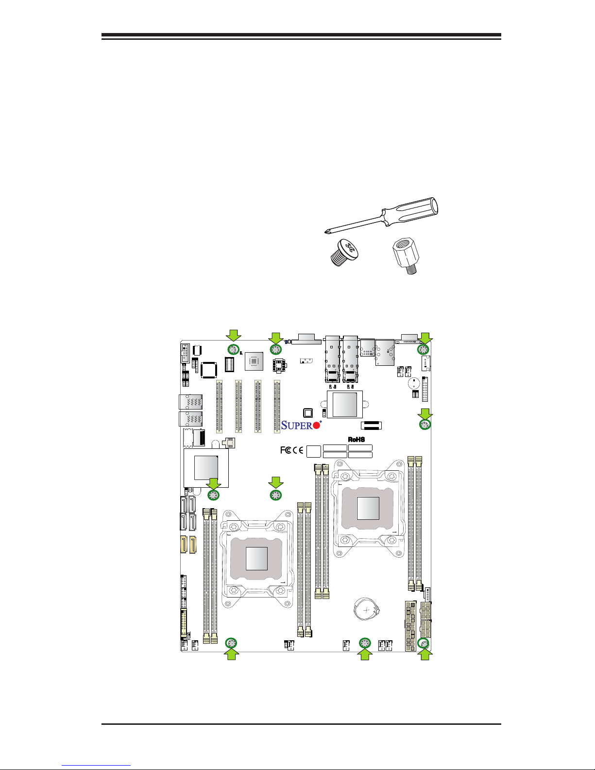
Location of Mounting Holes
There are nine (9) mounting holes on this motherboard as indicated by the arrows.
Caution: 1) To avoid damaging the motherboard and its components, do not use a
force greater than 8 lb/inch on each mounting screw during motherboard installation.
2) Some components are very close to the mounting holes. Please use caution to
prevent damage to these components when installing the motherboard to the chassis.
2-6
X10DRD-iTP/iNTP/LTP Motherboard User’s Manual
Installing the Motherboard
Note: Always connect the power cord last, and always remove it before
adding, removing, or changing any hardware components.
1. Install the I/O shield into the chassis.
2. Locate the mounting holes on the motherboard.
3. Locate the matching mounting holes on the chassis. Align the mounting holes
on the motherboard against the mounting holes on the chassis.
4. Install standoffs in the chassis if needed.
5. Install the motherboard into the chassis carefully to avoid damaging mother-
board components.
6. Using the Phillips screwdriver, insert a panhead #6 screw into a mounting
hole on the motherboard and its matching mounting hole on the chassis.
7. Repeat Step 5 to insert #6 screws into all mounting holes.
8. Make sure that the motherboard is securely placed in the chassis.
Note: Images displayed are for illustration only. Your chassis or compo-
nents might look different from those shown in this manual.
Chapter 2: Installation
2-7
2-4 Processor and Heatsink Installation
Warning: When handling the processor package, avoid placing direct pressure on the
label area. Also, improper CPU installation and socket/pin misalignment may cause
serious damage to the CPU or the motherboard that will require RMA repairs. Be sure
to read and follow all instructions thoroughly before installing your CPU and heatsink.
Notes:
Always connect the power cord last, and always remove it before adding,
removing, or changing any hardware components. Make sure that you in-
stall the processor into the CPU socket before you install the CPU heatsink.
If you buy a CPU separately, make sure that you use an Intel-certied
multidirectional heatsink only.
Make sure to install the motherboard into the chassis before you install
the CPU heatsink.
If you receive a motherboard without a processor preinstalled, make sure
that the plastic CPU socket cap is in place and that none of the socket
pins are bent; otherwise, contact your retailer immediately.
Refer to the Supermicro website for updates on CPU support.
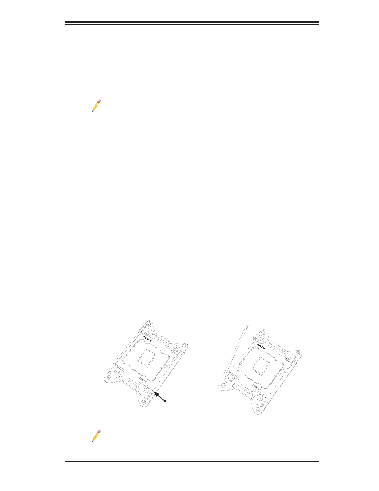
Installing the LGA2011 Processor
1. There are two load levers on the LGA2011 socket. To open the socket cover,
rst press and release the load lever labeled "Open 1st."
Note: All graphics, drawings, and pictures shown in this manual are for
illustration only. The components that came with your machine may or may
not look exactly the same as those shown in this manual.
Press down on
load lever labeled
"Open 1st"
1
2
OPEN 1st
OPEN 1st
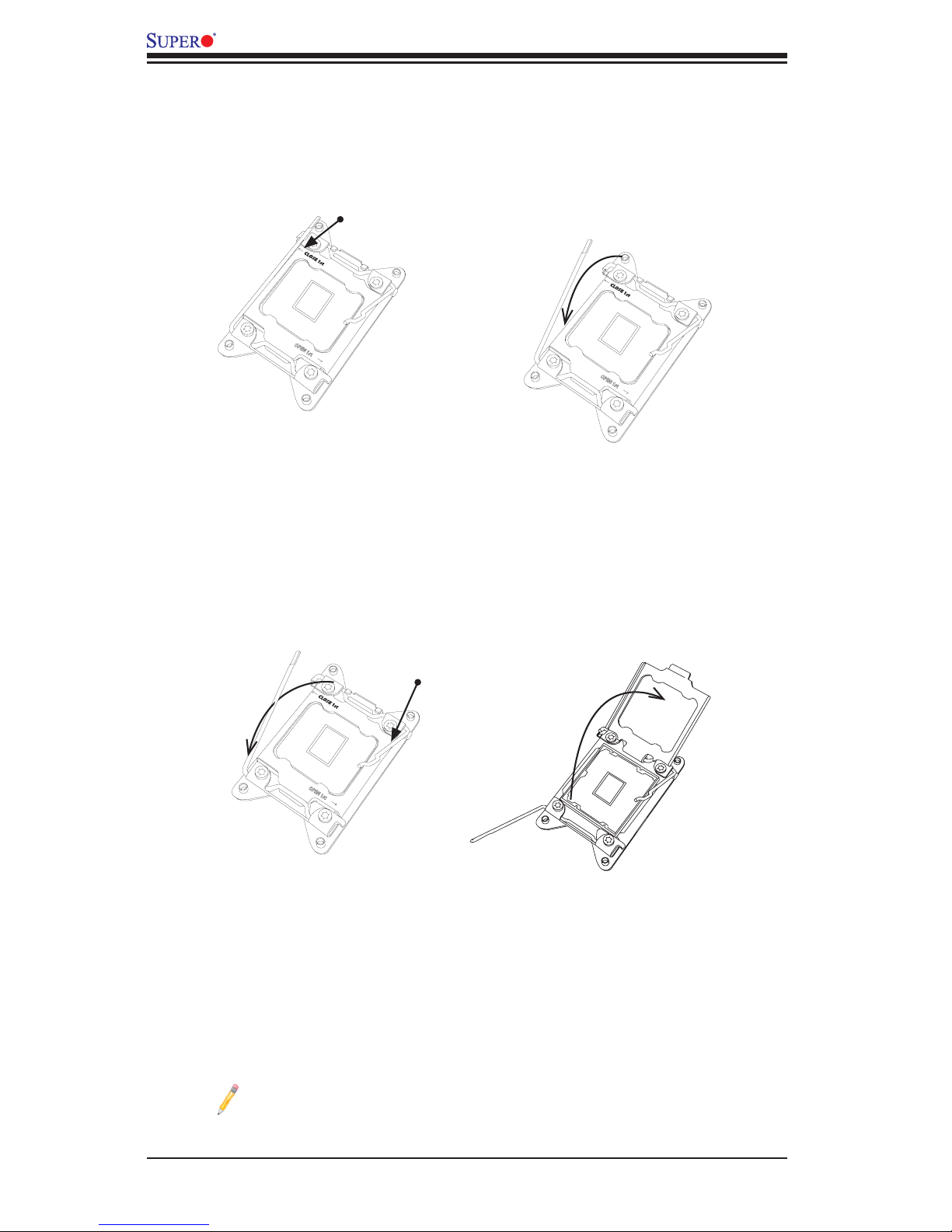
2-8
X10DRD-iTP/iNTP/LTP Motherboard User’s Manual
OPEN 1st
Gently push
down to pop the
load plate open
2. Press the second load lever labeled "Close 1st" to release the load plate that
covers the CPU socket from its locking position.
3. With the lever labeled "Close 1st" fully retracted, gently push down on the
lever labeled "Open 1st" to open the load plate. Lift the load plate to open it
completely.
1
2
Press down on
load
lever "Close 1st"
Pull lever away from
socket
2
Note: All graphics, drawings and pictures shown in this manual are for il-
lustration only. The components that came with your machine may or may
not look exactly the same as those shown in this manual.
OPEN 1st
OPEN 1st
1
 Loading...