

Supermicro Supero SC731 Series, Supero SC731D-300B, Supero SC731i-300B User Manual
SC731 CHASSIS SERIES
USER’S MANUAL
1.0b
SC731D-300B SC731i-300B
SUPER
®

SC731 Chassis Manual
ii
Manual Revision 1.0a
Release Date: August 14, 2009
The information in this User’s Manual has been carefully reviewed and is believed to be accurate.
The vendor assumes no responsibility for any inaccuracies that may be contained in this document,
makes no commitment to update or to keep current the information in this manual, or to notify any
person or organization of the updates. Please Note: For the most up-to-date version of this
manual, please see our web site at www.supermicro.com.
Super Micro Computer, Inc. ("Supermicro") reserves the right to make changes to the product
described in this manual at any time and without notice. This product, including software, if any,
and documentation may not, in whole or in part, be copied, photocopied, reproduced, translated or
reduced to any medium or machine without prior written consent.
IN NO EVENT WILL SUPERMICRO BE LIABLE FOR DIRECT, INDIRECT, SPECIAL, INCIDENTAL,
SPECULATIVE OR CONSEQUENTIAL DAMAGES ARISING FROM THE USE OR INABILITY TO
USE THIS PRODUCT OR DOCUMENTATION, EVEN IF ADVISED OF THE POSSIBILITY OF
SUCH DAMAGES. IN PARTICULAR, SUPERMICRO SHALL NOT HAVE LIABILITY FOR ANY
HARDWARE, SOFTWARE, OR DATA STORED OR USED WITH THE PRODUCT, INCLUDING THE
COSTS OF REPAIRING, REPLACING, INTEGRATING, INSTALLING OR RECOVERING SUCH
HARDWARE, SOFTWARE, OR DATA.
Any disputes arising between manufacturer and customer shall be governed by the laws of Santa
Clara County in the State of California, USA. The State of California, County of Santa Clara shall
be the exclusive venue for the resolution of any such disputes. Super Micro's total liability for
all claims will not exceed the price paid for the hardware product.
California Best Management Practices Regulations for Perchlorate Materials: This Perchlorate
warning applies only to products containing CR (Manganese Dioxide) Lithium coin cells. “Perchlorate
Material-special handling may apply. See www.dtsc.ca.gov/hazardouswaste/perchlorate”
WARNING: Handling of lead solder materials used in this
product may expose you to lead, a chemical known to
the State of California to cause birth defects and other
reproductive harm.
Unless you request and receive written permission from Super Micro Computer, Inc., you may not
copy any part of this document.
Information in this document is subject to change without notice. Other products and companies
referred to herein are trademarks or registered trademarks of their respective companies or mark
holders.
Copyright © 2009 by Super Micro Computer, Inc.
All rights reserved.
Printed in the United States of America

iii
Preface
Preface
About This Manual
This manual is written for professional system integrators and PC technicians. It
provides information for the installation and use of the SC731 chassis. Installation
and maintenance should be performed by experienced technicians only.
Supermicro’s SC731 chassis features a unique and highly optimized design, allow-
ing the user to install components with minimal or no use of screws or tools. The
chassis is equipped with a 300 Watt whisper-quiet, high-efciency power supply
for superb power savings.
This manual lists compatible parts available when this document was published.
Always refer to the our Web site for updates on supported parts and congurations
at www.supermicro.com.

SC731 Chassis Manual
iv
Manual Organization
Chapter 1: Introduction
The rst chapter provides a description of the main components included with this
chassis and describes the main features of the SC731 chassis. This chapter also
includes contact information.
Chapter 2: System Safety
This chapter lists warnings, precautions, and system safety. It is recommended that
you thoroughly familiarize yourself with the safety precautions before installing and
servicing this chassis.
Chapter 3: System Interface
Refer to this chapter for details on the system interface, which includes the functions
and information provided by the control panel on the chassis as well as other LEDs
located throughout the system.
Chapter 4: Chassis Setup and Maintenance
Follow the procedures given in this chapter when installing, removing, or
reconguring your chassis.
Appendix A: Chassis Cables, Screws and other Accessories
Appendix B: Power Supply Specications

v
Preface
Table of Contents
Chapter 1 Introduction
1-1 Overview ......................................................................................................... 1-1
1-2 Where to get Replacement Components ........................................................ 1-1
1-3 Shipping Lists ..................................................................................................1-1
1-4 Returning Merchandise for Service................................................................. 1-2
1-5 Contacting Supermicro .................................................................................... 1-3
Chapter 2 System Safety
2-1 Overview ......................................................................................................... 2-1
2-2 Warnings and Precautions .............................................................................. 2-1
2-3 Preparing for Setup ......................................................................................... 2-1
2-4 Electrical Safety Precautions .......................................................................... 2-1
2-5 General Safety Precautions ............................................................................ 2-2
2-6 System Safety ................................................................................................. 2-3
Chapter 3 System Interface
3-1 Overview ......................................................................................................... 3-1
3-2 Control Panel Buttons ..................................................................................... 3-2
3-3 Control Panel LEDs ........................................................................................ 3-2
Chapter 4 Chassis Setup and Maintenance
4-1 Overview ......................................................................................................... 4-1
4-2 Removing the Chassis Cover ......................................................................... 4-2
4-3 Rotating the Hard Drive Cage......................................................................... 4-3
4-4 Removing and Installing Hard Drives ............................................................. 4-4
4-5 Installing the I/O Shield and Motherboard ...................................................... 4-7
I/O Shield ........................................................................................................ 4-7
Permanent Motherboard Standoffs ................................................................. 4-7
Motherboard Installation .................................................................................. 4-8
4-6 Installing an Optical Device ............................................................................ 4-9
4-7 Installing Add-on and Expansion Cards ........................................................ 4-10
Add-on Card/Expansion Slot Setup .............................................................. 4-10
Long Add-on/Expansion Card Setup ..............................................................4-11
4-8 Installing the System Fan ............................................................................. 4-12
4-9 Installing the Front Bezel .............................................................................. 4-13
4-10 Power Supply ............................................................................................... 4-14
Appendix A Cables, Screws, and other Accessories
Appendix B SC731 Power Supply Specications

SC731 Chassis Manual
vi
Notes
Chapter 1
Introduction
1-1 Overview
Supermicro’s SC731 chassis features a unique and highly-optimized design, allow-
ing most conguration of the chassis to be accomplished without tools or screws.
The chassis is equipped with high-efciency power supply. High-performance fans
provide ample optimized cooling for FB-DIMM memory modules, and four hot-swap
drive bays offer maximum storage capacity.
1-2 Where to get Replacement Components
Although not frequently, you may need replacement parts for your system. To
ensure the highest level of professional service and technical support, we strongly
recommend purchasing exclusively from our Supermicro Authorized Distributors/
System Integrators/Resellers. A list of Supermicro Authorized Distributors/System
Integrators/Reseller can be found at: http://www.supermicro.com. Click the Where
to Buy link.
1-3 Shipping Lists
Please visit the following link for the latest shiping lists and part numbers for
your particular chassis model http://www.supermicro.com/products/chassis/
tower/?chs=731
Chapter 1: Introduction
1-1
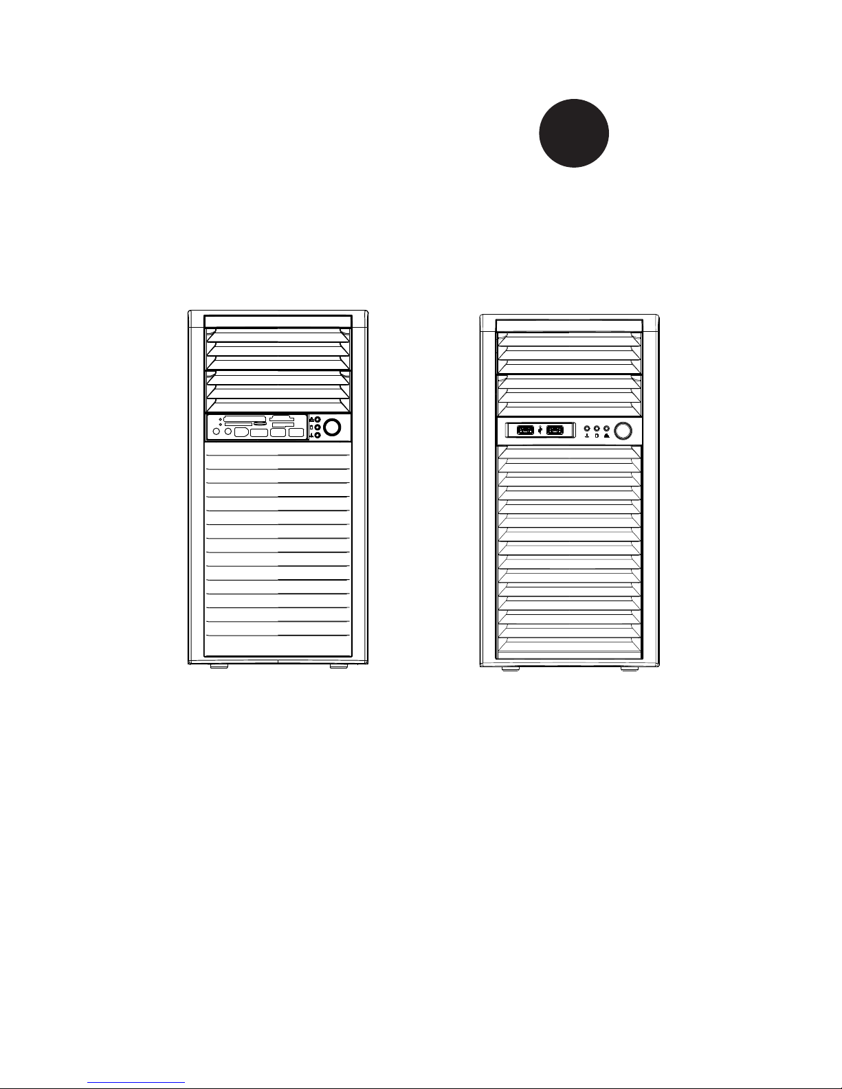
SC731D-300B Chassis
Model CPU HDD I/O Slots
Power
Supply
SC731D-300B
UP
4x 3.5"
2x 5.25"
1x 3.5" for
card reader
4x FF
300W
High-
efciency

SC731 Chassis Manual
1-2
SC731i-300B Chassis
Model CPU HDD I/O Slots
Power
Supply
SC731i-300B
UP
4x 3.5"
2x 5.25" 4x FF
300W
High-
efciency

1-3
Chapter 1: Introduction
1-4 Contacting Supermicro
Headquarters
Address: Super Micro Computer, Inc.
980 Rock Ave.
San Jose, CA 95131 U.S.A.
Tel: +1 (408) 503-8000
Fax: +1 (408) 503-8008
Email: marketing@supermicro.com (General Information)
support@supermicro.com (Technical Support)
Web Site: www.supermicro.com
Europe
Address: Super Micro Computer B.V.
Het Sterrenbeeld 28, 5215 ML
's-Hertogenbosch, The Netherlands
Tel: +31 (0) 73-6400390
Fax: +31 (0) 73-6416525
Email: sales@supermicro.nl (General Information)
support@supermicro.nl (Technical Support)
rma@supermicro.nl (Customer Support)
Asia-Pacic
Address: Super Micro Computer, Inc.
4F, No. 232-1, Liancheng Rd.
Chung-Ho 235, Taipei County
Taiwan, R.O.C.
Tel: +886-(2) 8226-3990
Fax: +886-(2) 8226-3991
Web Site: www.supermicro.com.tw
Technical Support:
Email: support@supermicro.com.tw
Tel: 886-2-8226-1900

SC731 Chassis Manual
1-4
1-5 Returning Merchandise for Service
A receipt or copy of your invoice marked with the date of purchase is required be-
fore any warranty service will be rendered. You can obtain service by calling your
vendor for a Returned Merchandise Authorization (RMA) number. When returning
to the manufacturer, the RMA number should be prominently displayed on the
outside of the shipping carton, and mailed prepaid or hand-carried. Shipping and
handling charges will be applied for all orders that must be mailed when service
is complete.
For faster service, RMA authorizations may be requested online (http://www.super-
micro.com/support/rma/).
Whenever possible, repack the chassis in the original Supermicro carton, using the
original packaging material. If these are no longer available, be sure to pack the
chassis securely, using packaging material to surround the chassis so that it does
not shift within the carton and become damaged during shipping.
This warranty only covers normal consumer use and does not cover damages in-
curred in shipping or from failure due to the alteration, misuse, abuse or improper
maintenance of products.
During the warranty period, contact your distributor rst for any product problems

2-1
Chapter 2: System Safety
Chapter 2
System Safety
2-1 Overview
This chapter provides a quick setup checklist to get your chassis up and running.
Following the steps in the order given should enable you to have your chassis setup
and operational within a minimal amount of time. This quick setup assumes that you
are an experienced technician, famailiar with common concepts and terminology.
2-2 Warnings and Precautions
You should inspect the box the chassis was shipped in and note if it was damaged
in any way. If the chassis itself shows damage, le a damage claim with carrier
who delivered your system.
Avoid areas where heat, electrical noise and eletromagnetic elds are generated.
Position the chassis near at least one grounded power outlet.
2-3 Preparing for Setup
The SC731 chassis contains many features that are unique to the SC731 chassis
model. Read this manual in its entirety before beginning the installation proce-
dure.
2-4 Electrical Safety Precautions
Basic electrical safety precautions should be followed to protect yourself from harm
and the SC731 from damage:
Be aware of the locations of the power on/off switch on the chassis as well •
as the room’s emergency power-off switch, disconnection switch or electrical
outlet. If an electrical accident occurs, you can then quickly remove power from
the system.
Do not work alone when working with high voltage components.•
Power should always be disconnected from the system when removing or in-•
stalling main system components, such as the serverboard, memory modules
 Loading...