

Supermicro SC-830W, SC-820W User Manual
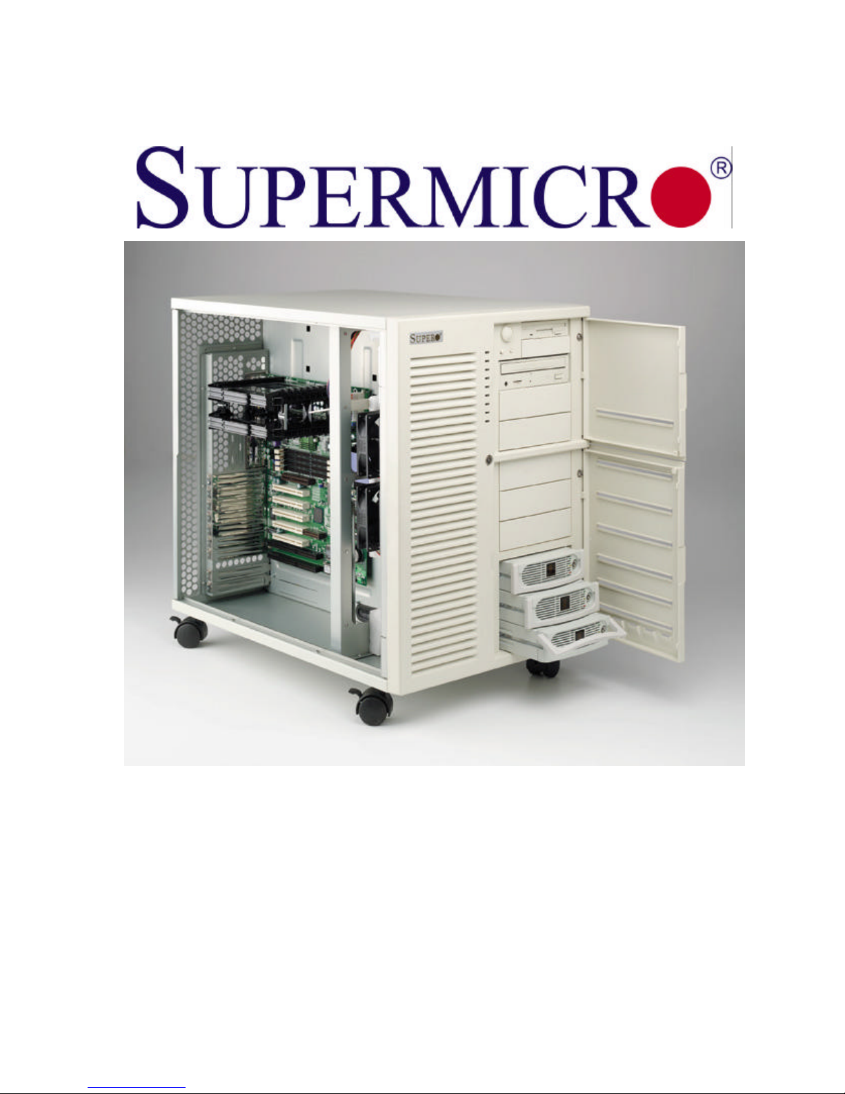
SC-830W CHASSIS
SC-820W CHASSIS
USER’S MANUAL
Revision 1.1
Page
Chapter 1
SC830W/SC820W CHASSIS
I. Chassis Specifications
Dimensions: 380 x 505 x 570 mm ( W x H x D)
A. Drive bay: 5.25” x 9, 3.5” x 2
B. 9 expansion slots
C. lockable side door and front door
D. Power Supply:
SC830W --Dual Redundant 300W ATX 2.03 compliant
SC820W-- Single Redundant Cooling 400W ATX 2.03 compliant
E. Maximum board size : 18” x 13”
F. Cooling system: Two sections of cooling. One cooling system for each chamber of the chassis.
1) On the Hard Disk Drive side—two of 12-cm exhaust fans.
2) On the Main board side – There are two cartridges on the front. Inside each cartridge, there are two
cooling fans. Each fan is 9-cm with 3-pin connector.
3) Two Fan deflectors and two fan door-blocks are also included. These deflectors are designed to
optimize airflow, and the fan-door blocks to prevent hot air from being drawn back.
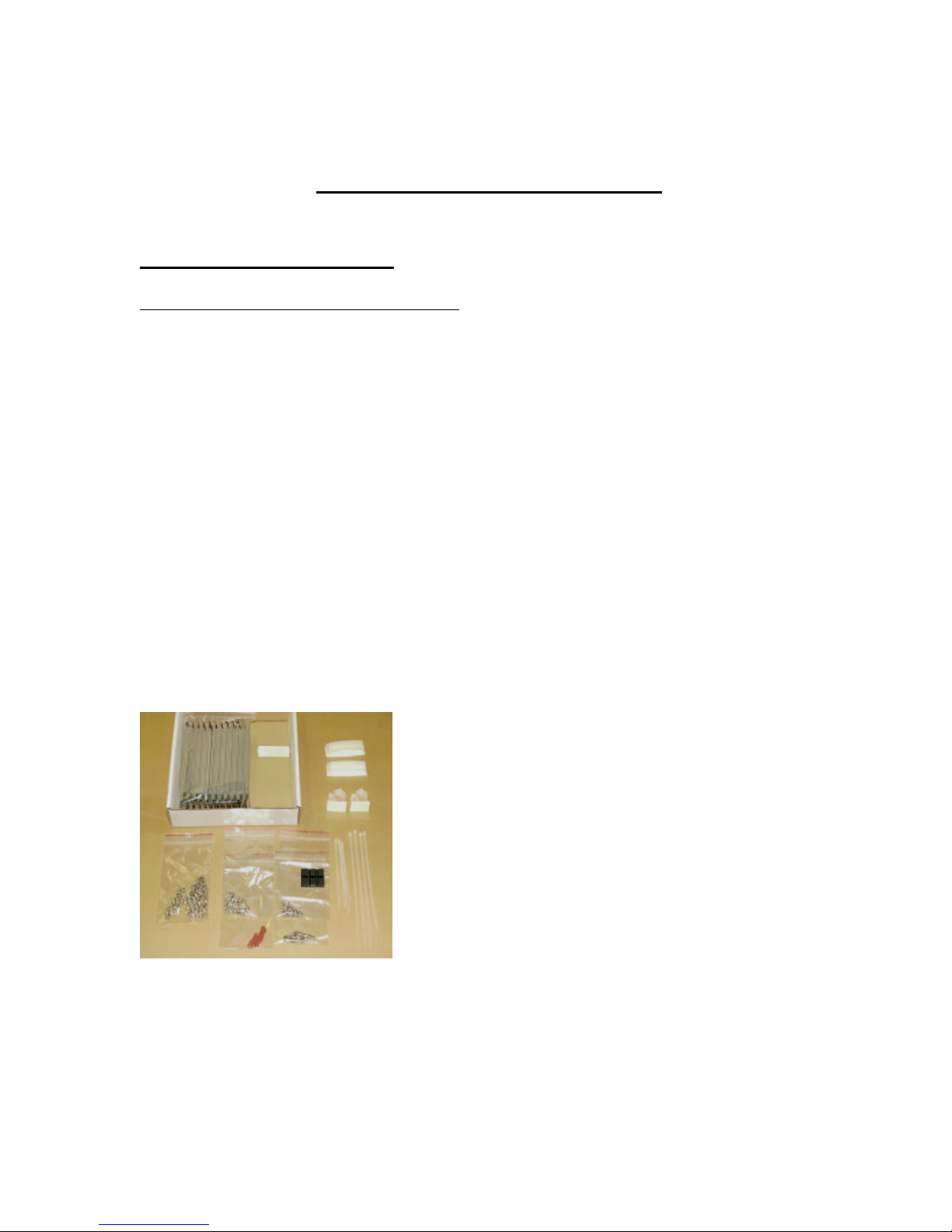
H. Parts included: Mounting kits, drive bay rails (11 pairs), rubber stands, cables and wires tie wraps.
1
Page
2. Installation Procedures
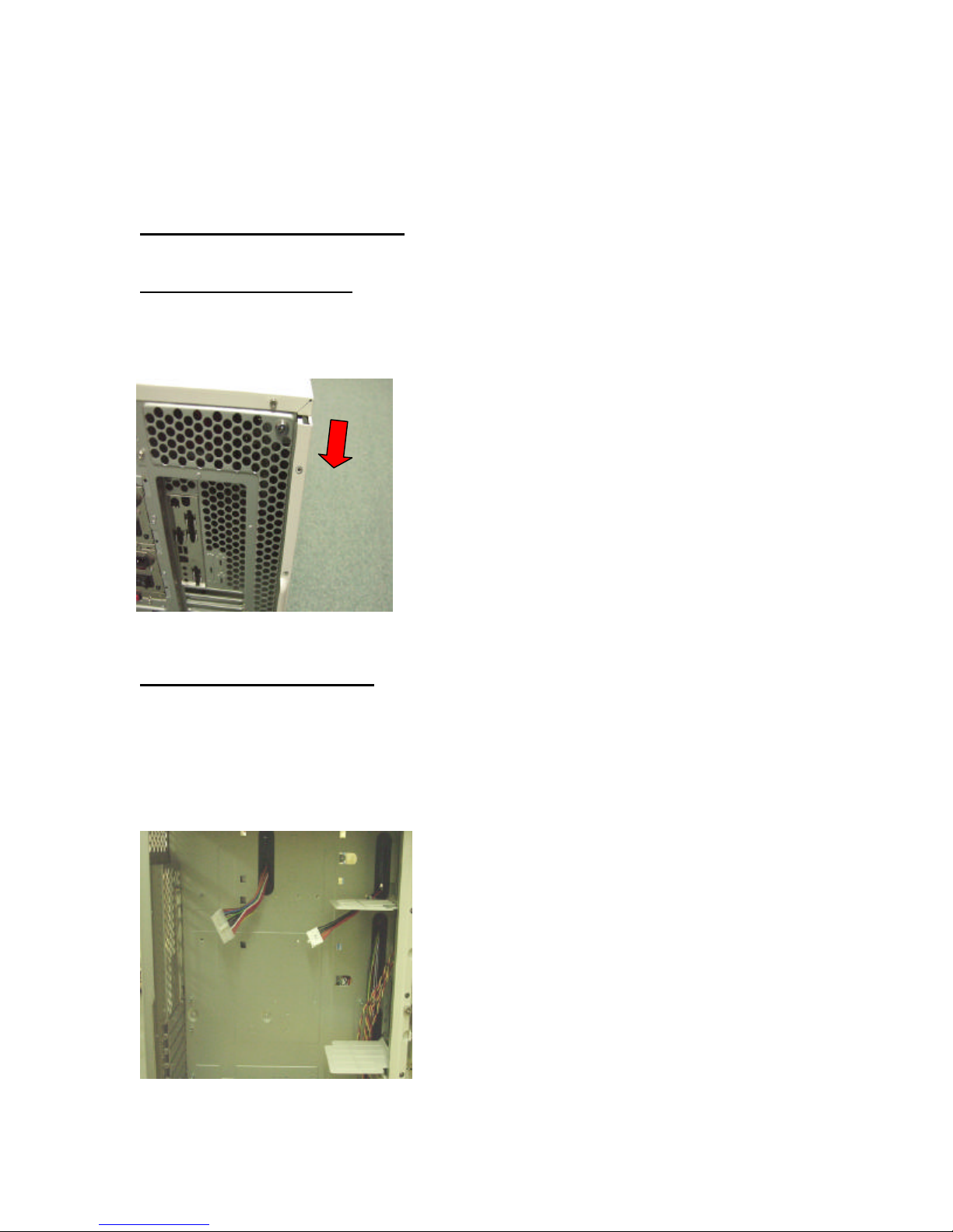
To Open the Side Doors:
Please locate 4 holes and a lock on the motherboard sides of chassis. Unscrew the four screws on the side door,
and the door will be unlocked. Move the doors slightly upward to open the door. Both side doors are unlocked
by default. However, if you lock one side door by using the key provided, both doors will be locked.
To Install the Motherboard:
A. Check if the I/O port fits your chassis I/O plate or not. (They are several kinds of I/O shield standards. The
default I/O for this chassis is Venus with punch out plug for the sound port.)
B. Check the mounting holes on the motherboard to see if they align with the mounting stands on the chassis. If
not, add or remove the mounting stands to match the mounting holes on the board with the holes on the chassis.
C. Remove the unnecessary mounting stands under the motherboard to avoid shorting the circuitry on the
motherboard.
2
Page
To Attach the Black Rubber Standoffs to the Inside Motherboard Tray to
Unlock by moving
Function as Shock Absorbers.
To prevent the motherboard from being damaged by impact, please peel off the double-sided tape of the rubber
standoffs and attach the black rubber standoffs on the motherboard tray at the locations under the CPU and PCI
slots. This is especially important for the Xeon systems.
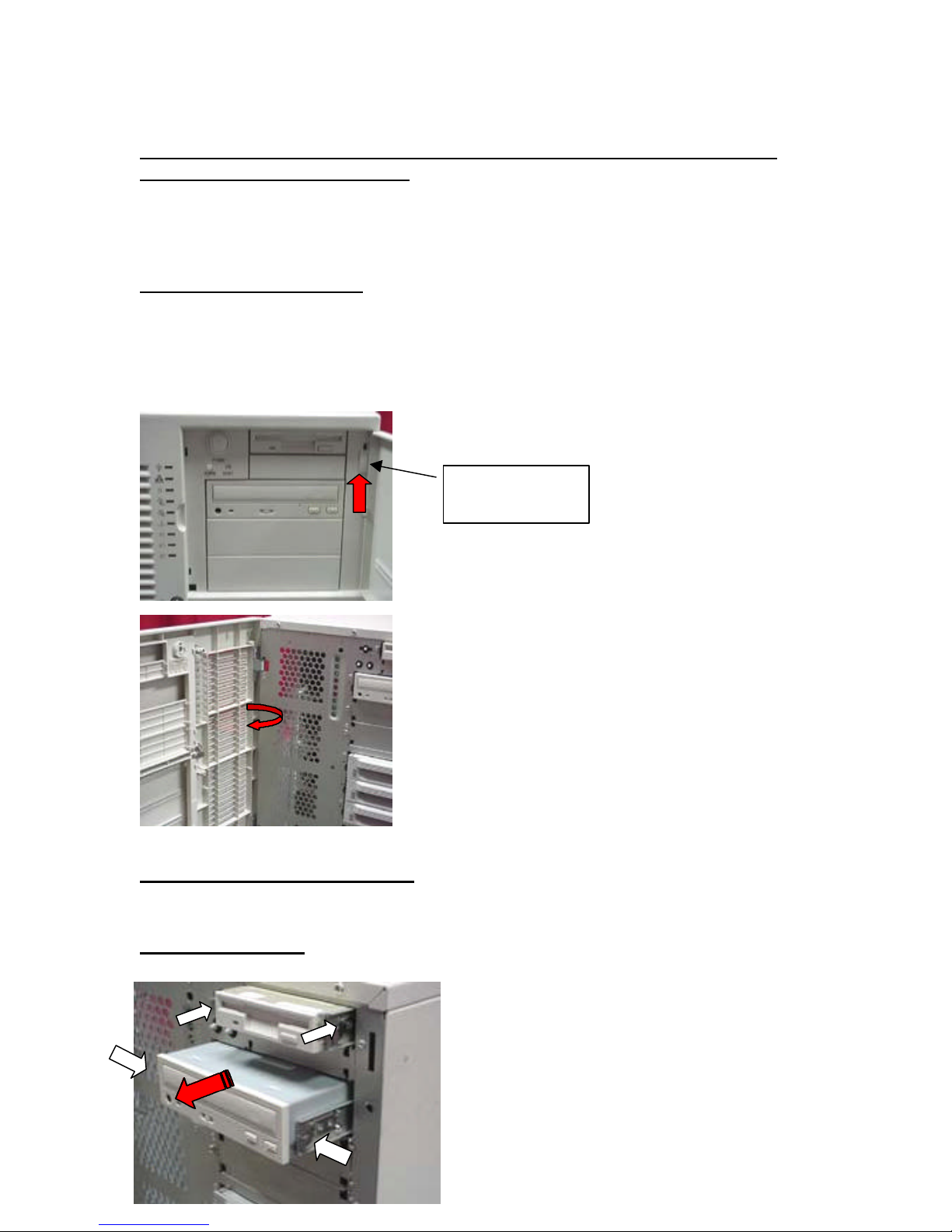
To Open the Front Panel:
Locate three locking tabs at the edge of the panel (The drive bay doors can be detached if needed.) Slide the
locking tabs upward and the door will swing open. To detach the front panel, you need to open the panel to a
wide angle (--the angle should be greater than 90 degrees) and move it slightly upward to slide the panel out of
its position.
up the locking tab
To Install the Device in the Bay:
All the drive bays need to have a pair of rails mounted to the device. Slide in the device until you hear the click,
and the device is in the locked position.
To remove the bay: squeeze the metal bars and pull the device out.
3
Page
To Install IDE , Floppy and SCSI Cables:
A. The chassis has eight cable access holes to enhance cable organization and to optimize airflow in the
chassis.
B. Locate eight cable holes inside the chassis. Route the cables through the closest cable access holes to the
best organize the cables and to increase airflow in the chassis.
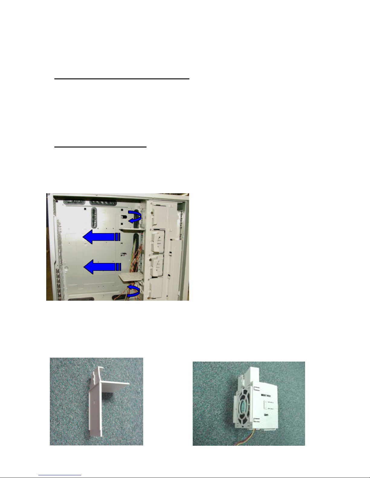
To Install the Cooling Device:
All fan cartridges, fan deflectors and fan door blocks are designed to optimize ventilation inside the chassis. If
a cooling fan is not installed into the cooling fan slot, you need to install the door block in the slot to prevent
drawing hot air back into the motherboard side of the chassis.
For best ventilation, please keep both side-doors closed at all time.
Fan Door block Dual Fan with cartridge
4
 Loading...