

Supermicro SC818 User Manual
SUPER
®
The SC818 Chassis Series
User Guide
Rev. 1.0

SC818 Chassis User's Guide
The information in this User’s Manual has been carefully reviewed and is believed to be accurate.
The vendor assumes no responsibility for any inaccuracies that may be contained in this document,
makes no commitment to update or to keep current the information in this manual, or to notify any
person or organization of the updates.
Please Note: For the most up-to-date version of this manual, please see our web
site at www.supermicro.com.
SUPERMICRO COMPUTER reserves the right to make changes to the product described in this
manual at any time and without notice. This product, including software, if any, and documentation may not, in whole or in part, be copied, photocopied, reproduced, translated or reduced to any
medium or machine without prior written consent.
IN NO EVENT WILL SUPERMICRO COMPUTER BE LIABLE FOR DIRECT, INDIRECT, SPECIAL,
INCIDENTAL, OR CONSEQUENTIAL DAMAGES ARISING FROM THE USE OR INABILITY TO
USE THIS PRODUCT OR DOCUMENTATION, EVEN IF ADVISED OF THE POSSIBILITY OF
SUCH DAMAGES. IN PARTICULAR, THE VENDOR SHALL NOT HAVE LIABILITY FOR ANY
HARDWARE, SOFTWARE, OR DATA STORED OR USED WITH THE PRODUCT, INCLUDING THE
COSTS OF REPAIRING, REPLACING, INTEGRATING, INSTALLING OR RECOVERING SUCH
HARDWARE, SOFTWARE, OR DATA.
Any disputes arising between manufacturer and customer shall be governed by the laws of Santa
Clara County in the State of California, USA. The State of California, County of Santa Clara shall
be the exclusive venue for the resolution of any such disputes. Supermicro's total liability for all
claims will not exceed the price paid for the hardware product.
Manual Revision: Rev. 1.0
Release Date: March 20, 2006
Unless you request and receive written permission from SUPER MICRO COMPUTER, you may not
copy any part of this document.
Information in this document is subject to change without notice. Other products and companies
referred to herein are trademarks or registered trademarks of their respective companies or mark
holders.
Copyright © 2006 by SUPER MICRO COMPUTER INC.
All rights reserved.
Printed in the United States of America
1-2

Chapter 1: Introduction
Table of Contents
Chapter I: Introduction .................................................................1-4
A. Safety Guidelines ......................................................................................... 1-4
B. Packing Lists ................................................................................................ 1-6
C. SC818 Chassis Front Panel ........................................................................ 1-8
D. The SC818 Chassis Specifi cations ............................................................ 1-10
E. The SC818 Chassis Power Supply Specifi cations .....................................1-11
Chapter 2: Installation Procedures ..............................................2-1
Section 1: Installing components into the SC818 Chassis ...........2-1
A. Removing the Top Cover of the SC818 Chassis ......................................... 2-1
B. Removing the Riser Card Bracket from the Chassis ................................. 2-2
C. Installing the Motherboard into the Chassis ................................................ 2-3
D. Installing the Chipset Air Shroud into the Chassis ...................................... 2-5
E. Installing the CPU Air Shroud into the Chassis ........................................... 2-6
F. Accessing the Hard Disk Drive Tray and Installing a Hard Drive ............... 2-7
G. Rail Installation ............................................................................................ 2-8
H. Installing the Chassis into the Rack .......................................................... 2-10
Section 2: SCSI (Super) GEM Driver Installation Instructions for the
Windows Operating System ............................................................. 2-6
Appendix: SCA 818S User's Guide ............................................ A-1
1-3
SC818 Chassis User's Guide
Chapter 1- Introduction
A. Safety Guidelines
A-1 Electricity Safety
General Electrical Safety Guidelines
Use the exact type of power cords as required.
!
•
Be sure to use power cord(s) that came with safety certifi ca-
•
tions.
The power cord(s) must be compliant with the AC voltage require-
•
ments in your region.
Plug the Power cord(s) into a socket that is properly grounded
•
before turning on the power.
Take extra precautionary measures when working with high voltage
•
components. It is not recommended to work alone.
Before removing or installing chassis components, be sure to
•
disconnect the power fi rst. Turn off the system before you dis-
connect the power supply.
A-2. ESD Safety Guidelines
Electric Static Discharge (ESD) can damage electronic com ponents. To
prevent damage to your system board, it is important to handle it very
!
carefully. The following measures are generally suffi cient to protect your
equipment from ESD.
Use a grounded wrist strap designed to prevent static discharge.
•
Keep all components and printed circuit boards (PCBs) in their antistatic bags
•
until ready for use.
Touch a grounded metal object before removing chassis components or the
•
motherboard from the antistatic bag.
Do not let components or PCBs come into contact with your clothing, which
•
may retain a charge even if you are wearing a wrist strap.
Handle a motherboard by its edges only; do not touch its components, peripheral
•
chips, memory modules or contacts.
When handling processors, chips or modules, avoid touching their pins.
•
Put the motherboard or components back into their antistatic bags when not
•
in use.
For the grounding purpose, make sure that your chassis provides excellent
•
conductivity between the power supply, the case, the mounting fasteners and
the motherboard.
1-4
A-3. General Safety Guidelines
Chapter 1: Introduction
Warning!!
!
damage to the system or injury to yourself:
To avoid injuries to your back, be sure to use your leg muscles, keep your
•
back straight, and bend your knees, when lifting the system.
After removing the components or chassis covers from the system, place
•
them on a table for safeguard.
Avoid wearing loose clothing to preventing it from coming into contact with
•
electrical circuits or being pulled into a cooling fan.
The handles are for sliding the chassis in and out of the racks only. Do
•
not carry the chassis by the handles.
Follow the guidelines below to avoid possible
A-4. Operation Safety Guidelines
Warning: For proper cooling, make sure to install all chassis covers
before turning on the system. If this rule is not strictly followed, warranty
!
may become void. Do not open the casing of a power supply. Power
supplies can only be accessed and serviced by a qualifi ed technician of
the manufacturer. Be sure to follow the steps below to install the chassis
covers:
1. Make sure that all components and devices are securely fastened on the chassis
and there are no loose parts/screws inside the chassis.
2. Make sure that all cables are properly connected to the connectors and ports.
3. Use the original screws or fasteners to install the covers to the chassis.
4. Be sure to lock to the chassis or the system to prevent unauthorized access.
5. Please follow the procedures listed in Chapter 2 to install or remove components
to or from the SC818.
A-5. An Important Note to the User:
All images and graphics shown in this manual were based upon the latest chas-
sis Revision available at the time of publishing. The chassis you’ve received may
or may not look exactly the same as the graphics shown in this manual.
1-5
SC818 Chassis User's Guide
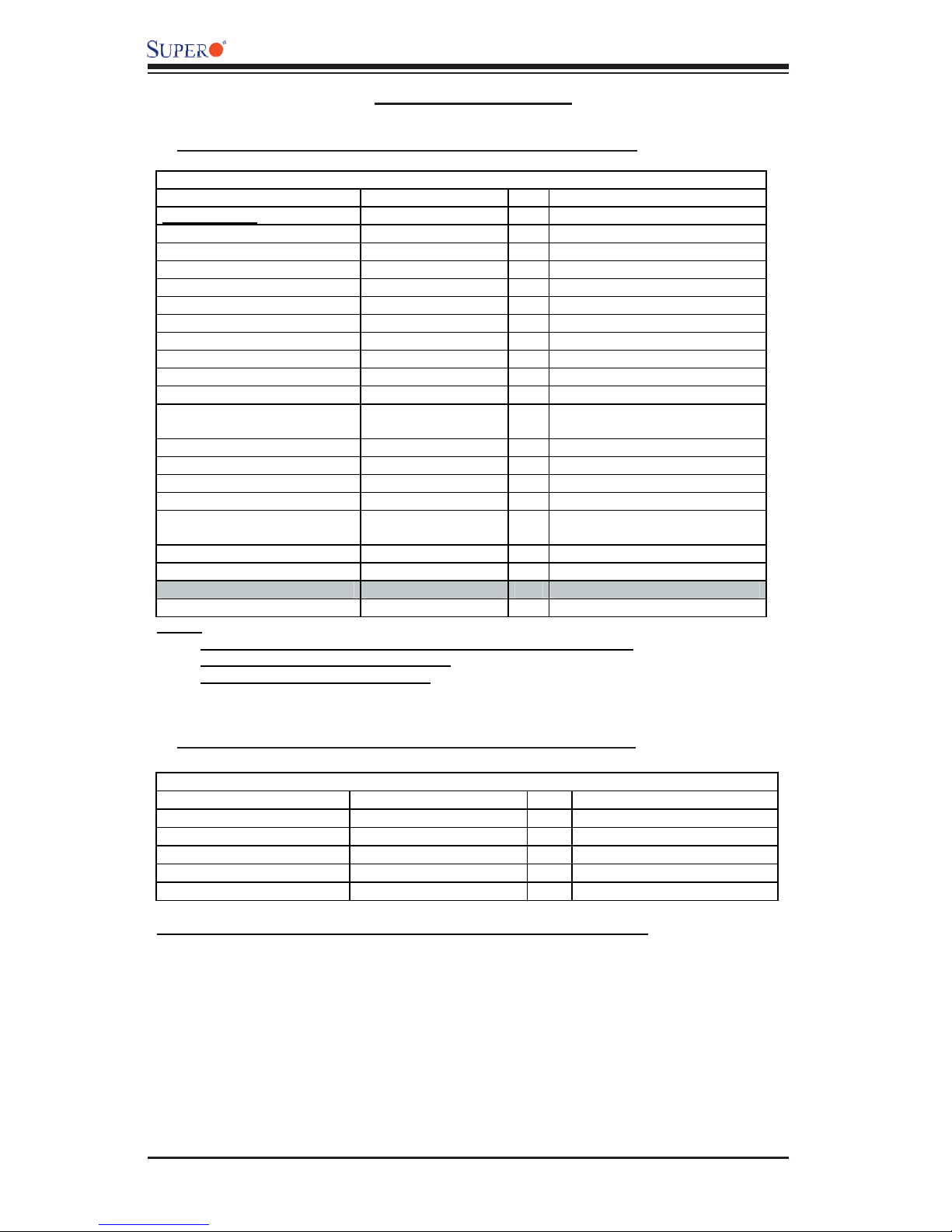
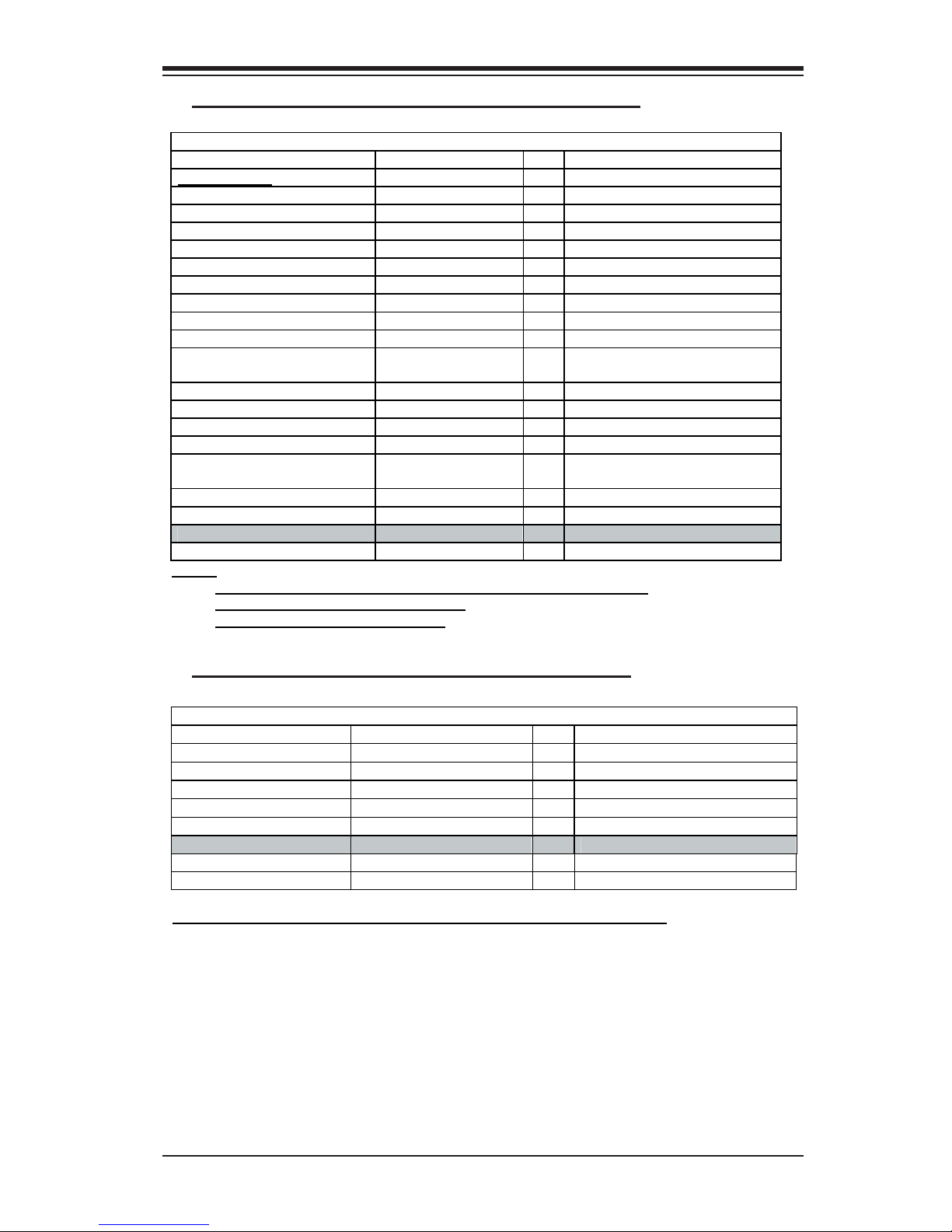
B. Packing Lists
B-1. The SC818+-1000 Chassis Packaging List:
The SC818+-1000 Chassis Packing List
Item Name Part Number Q'ty Notes
Chassis body
*Power supply PWS-1K01-1R 1 1000W
*Cooling fan (Chassis fan) FAN-0086 6 40x56 (Nidec) Dual blade 3 pin
*CPU Air Shroud CSE-PT-0128 1
Power Distributor CSE-PT818-PD284 1
Power Distributor Cover CSE-PT126 1
Chipset Air Shroud CSE-PT0115 1 With two Fan-0089
Slim DVD-ROM DVM-PNSC-824(B) 1
Slim DVD -ROM adapter SCD812 1
Slim Floppy device FPD-Teac-S (B) 0 Optional Item
Slim floppy adapter SFBP812 0 Optional Item
CD & floppy PWR converter
cable 07-01-813904-XX1 2
*Dummy CD-ROM Cover 0
*Dummy FDD Cover 1
*Hard drive carriers CSE-PT39(B) 4
*Front panel LED board 1
*Front panel control round
cable CBL-0049 1 Flat cable 54cm (cable)
DVD-ROM cable CBL-0139 1
Floppy cable CBL-0078 1 Optional Item
Backplane
Hard Drive Backplane CSE-SAS-818S 1 SuperMicro install item
Notes:
1. Items marked with “ * ” are included in the chassis packaging.
2. DVD-ROM & FDD are optional items.
3. Slide Rails have no Teflon Tapes.
CSE-818TS+-1000 1
B-2. The SC-818+-1000 Chassis Accessory Kit:
The SC818+-1000 Chassis
Item Name Part Number Q'ty Note
*Power cord 1
*Rail accessories CSE-PT51 1 1U Rail w/Teflon Tape
*Screw and tie wrap kits (A) B0-01-814O01-XXA 1
*Riser card bracket 1
*Accessory Box 1
Note: Items marked with “ * ” are included in the chassis packaging.
1-6
Chapter 1: Introduction
B-3. The SC818-1000 Chassis Packaging List:
The SC818 1000 Chassis Packing List
Item Name Part Number Q'ty Notes
Chassis body
*Power supply PWS-1K01-1R 1 1000W
*Cooling fan (Chassis fan) FAN-0086 6 40x56 (Nidec) Dual blade 3 pin
*CPU Air Shroud CSE-PT-0128 1
Power Distributor CSE-PT818-PD284 1
Power Distributor Cover CSE-PT126 1
Slim DVD-ROM DVM-PNSC-824(B) 1
Slim DVD -ROM adapter SCD812 1
Slim Floppy device FPD-Teac-S (B) 0 Optional Item
Slim floppy adapter SFBP812 0 Optional Item
CD & floppy PWR converter
cable 07-01-813904-XX1 2
*Dummy CD-ROM Cover 0
*Dummy FDD Cover 1
*Hard drive carriers CSE-PT39(B) 4
*Front panel LED board 1
*Front panel control round
cable CBL-0049 1 Flat cable 54cm (cable)
DVD-ROM cable CBL-0139 1
Floppy cable CBL-0078 1 Optional Item
Backplane
Hard Drive Backplane 1 SuperMicro install item
Notes:
1. Items marked with “ * ” are included in the chassis packaging.
2. DVD-ROM & FDD are optional items.
3. Slide Rails have no Teflon Tapes.
CSE-818 1000 1
B-4. The SC818-1000 Chassis Accessory Kit:
The SC818-1000
Item Name Part Number Q'ty Note
*Power cord 1
*Rail accessories CSE-PT51 1 1U Rail W/Teflon Tape
*Screw and tie wrap kits (A) B0-01-814O01-XXA 1
*Riser card bracket 1
*Accessory Box 1
Hard Drive Backplane
SATA cable CBL-0058 4 SuperMicro install item
SATA LED cable CBL-0056 1 SuperMicro install item
Note: Items marked with “ * ” are included in the chassis packaging.
1-7
SC818 Chassis User's Guide
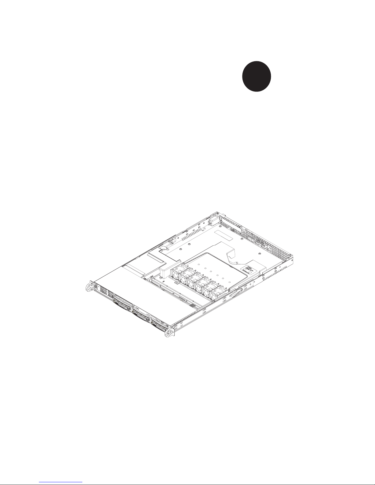
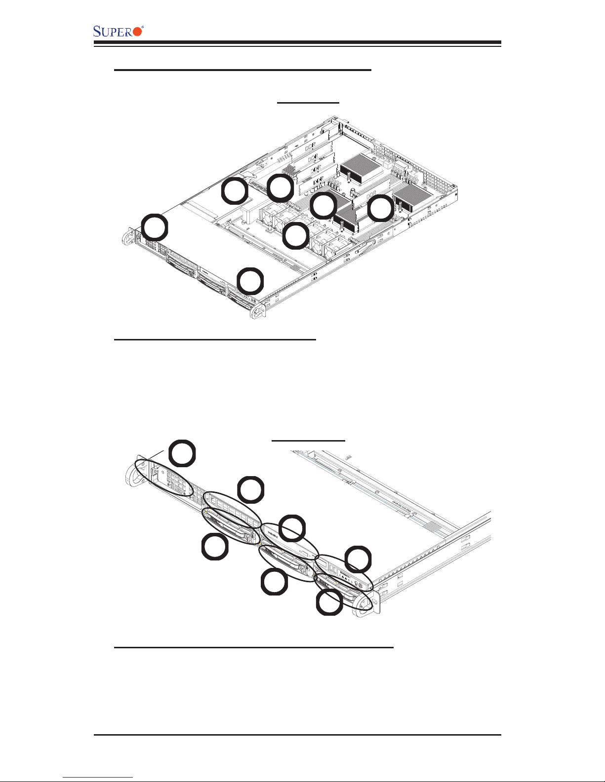
C. The SC818 Chassis Front Panel
Top View
6
3
6
5
7
2
4
1
C-1. Major Chassis Components
1. Front Control Panel (*See C-2 below)
2. Power Module 6. Chipset
3. Power Back Plane 7. DDR Memory Modules (8)
4. Fan Modules (6)
5. CPUs (4)
Front View
3
5
C-2. Front Panel LED Indicators and IO Ports
1. Front Panel LED Indicators (*See C-3 below)
2. CD-ROM/DVD-ROM
3. Power Supply Module
4. Hard Disk Drives (3)
5. Floppy Drive (optional)
2
4
1
4
4
1-8
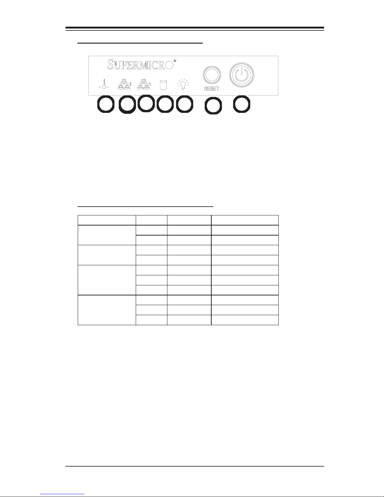
C-3. Front Panel LED Indicators
Chapter 1: Introduction
67
6
1. Power Button
2. Reset Button
3. Power-on LED
4. Hard Drive Activity LED
5. LAN Port1 LED
6. LAN Port2 LED
7. Overheat/Fan Fail LED
C-4. Front Panel LED Descriptions
LED Button Color Condition Description
LAN1 & LAN2
Overheat
5
Green On System On Power
Off System Off
Amber Blinking HDD Activity HDD
Off No Activity
Green On Linked
Blinking LAN Activity
Off Disconnected
Red On System Overheat
Off System Normal
Blinking Fan Failure
34
2
1
1-9
SC818 Chassis User's Guide
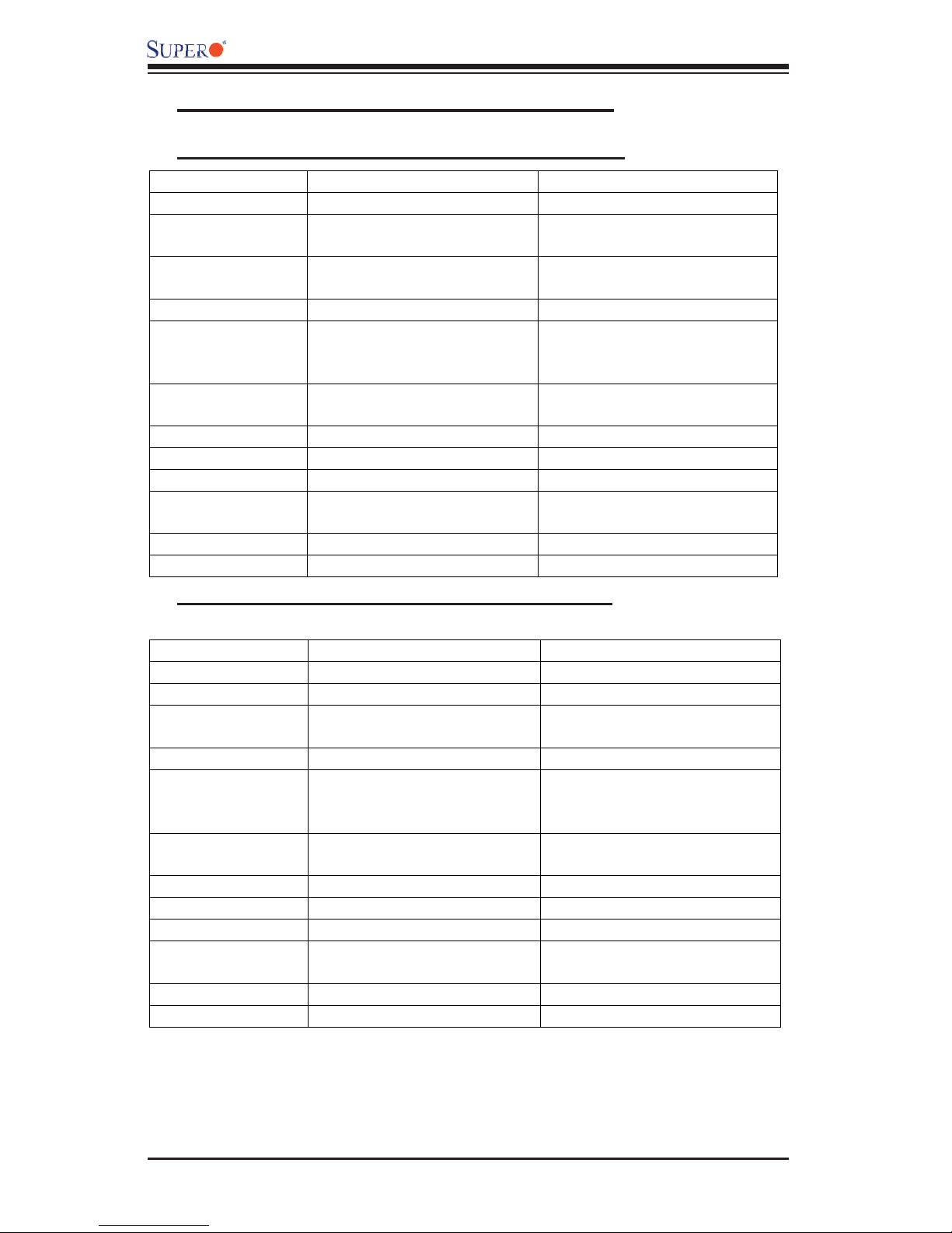
D. The SC818 Chassis Specifi cations
D-1. The SC818+-1000 Chassis Specifi cations
Model SC818S+-1000 SC818TQ+-1000
Form Factor
CPU Support
Max.
Motherboard Size
Expansion Slots
SCA or HD Bays
Front Side USB
Port &COM port
Floppy/CD-ROM
Power Supply
Cooling System
Dimension
(W x H x D)
Weight
Optional Kits
1U Rackmount 1U Rackmount
AMD Quad Opteron
Processors
ATX 13” x 16” ATX 13” x 16”
11
Three 1”hot-swap Ultra
320/160 SCSI drive bays
(SAF-TE Compliant)
Optional Optional
Optional/Yes Optional /Yes
1000W cold-swap PS 1000W cold-swap PS
Six 40mmx40mmx56mm Six 40mmx40mmx56mm
17.2” x 1.7” x 27.75”
(437mm x 43mm x 705 mm)
35 lb. (15.9 kg) 35 lb. (15.9 kg)
Riser Cards Riser Cards
AMD Quad Opteron
Processors
Three 1”hot-swap SATA bays
17.2” x 1.7” x 27.75”
(437mm x. 43mm x 705mm)
D-2. The SC818-1000 Chassis Specifi cations
Model SC818S-1000 SC818TQ-1000
Form Factor
CPU Support
Max.
Motherboard Size
Expansion Slots
SCA or HD Bays
Front Side USB
Port &COM port
Floppy/CD-ROM
Power Supply
Cooling System
Dimension
(W x H x D)
Weight
Optional Kits
1U Rackmount 1U Rackmount
Intel Quad Processors Intel Quad Processors
ATX 16” x 14.5” ATX 16” x 14.5”
11
Three 1”hot-swap Ultra
320/160 SCSI drive bays
(SAF-TE Compliant)
Yes Yes
Optional/Yes Optional/Yes
1000W cold-swap PS 1000W cold-swap PS
Six 40mmx40mmx56mm Six 40mmx40mmx56mm
17.2” x 1.7” x 27.75”
(437mm x 43mm x 705 mm)
35 lb. (15.9 kg) 35 lb. (15.9 kg)
Riser Cards Riser Cards
Three 1”hot-swap SATA bays
17.2” x 1.7” x 27.75”
(437mm x. 43mm x 705mm)
1-10
 Loading...