

Supermicro SC812L-280U, SC812L-410, SC812L-520C, SC812L-520U, SC812L-420 User Manual
...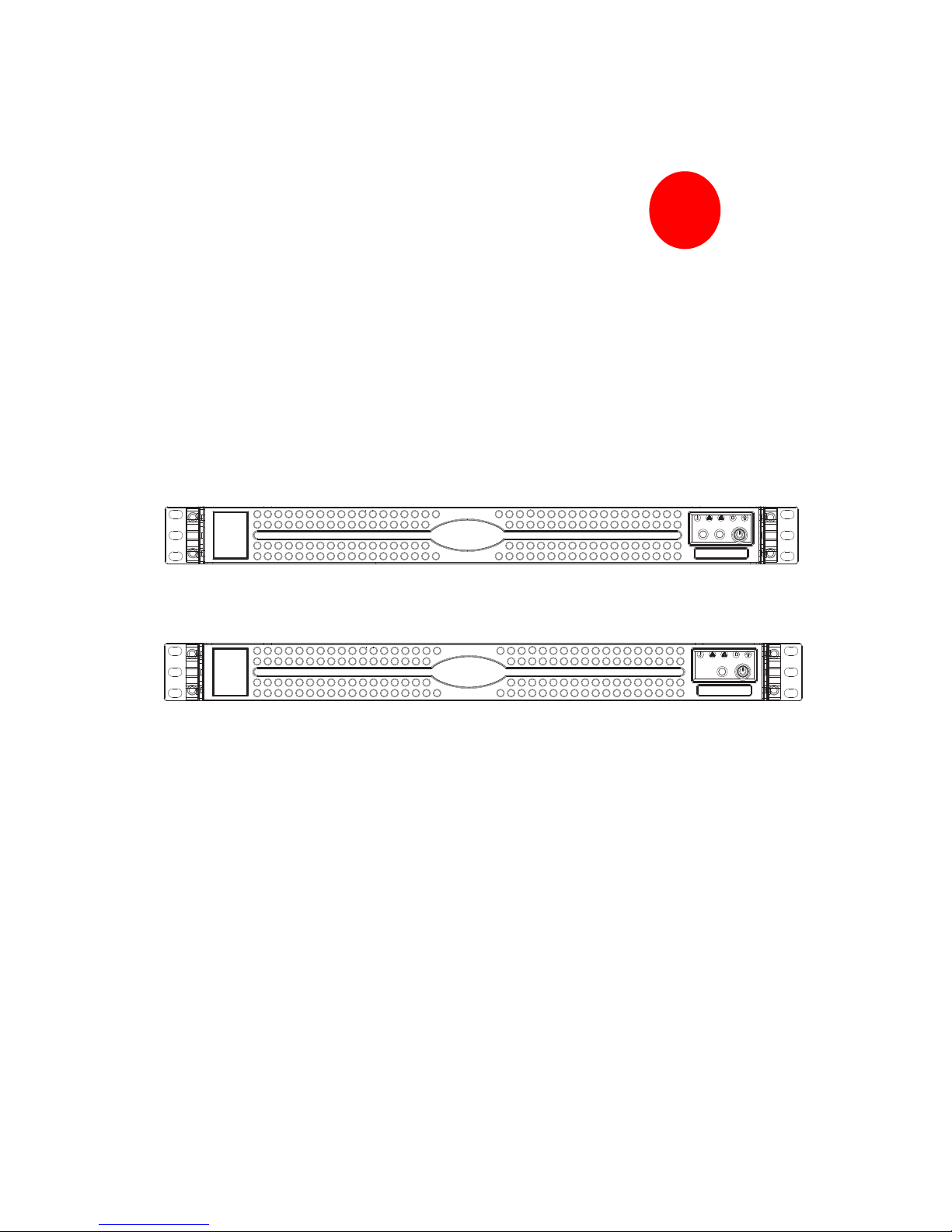
SC812L CHASSIS SERIES
SUPER
USER’S MANUAL
1.0
SC812L-520U SC812L-280U
SC812L-520 SC812L-420
SC812L-520C SC812L-420C
SC812L-410
SC812L-U
SC812L

SC812L Chassis Manual
ii
The information in this User’s Manual has been carefully reviewed and is believed to be accurate.
The vendor assumes no responsibility for any inaccuracies that may be contained in this document,
makes no commitment to update or to keep current the information in this manual, or to notify any
person or organization of the updates. Please Note: For the most up-to-date version of
this manual, please see our web site at www.supermicro.com.
SUPERMICRO COMPUTER reserves the right to make changes to the product described in this
manual at any time and without notice. This product, including software, if any, and documentation may not, in whole or in part, be copied, photocopied, reproduced, translated or reduced to any
medium or machine without prior written consent.
IN NO EVENT WILL SUPERMICRO COMPUTER BE LIABLE FOR DIRECT, INDIRECT, SPECIAL,
INCIDENTAL, SPECULATIVE OR CONSEQUENTIAL DAMAGES ARISING FROM THE USE
OR INABILITY TO USE THIS PRODUCT OR DOCUMENTATION, EVEN IF ADVISED OF THE
POSSIBILITY OF SUCH DAMAGES. IN PARTICULAR, THE VENDOR SHALL NOT HAVE
LIABILITY FOR ANY HARDWARE, SOFTWARE, OR DATA STORED OR USED WITH THE
PRODUCT, INCLUDING THE COSTS OF REPAIRING, REPLACING, INTEGRATING, INSTALLING
OR RECOVERING SUCH HARDWARE, SOFTWARE, OR DATA.
Any disputes arising between manufacturer and customer shall be governed by the laws of Santa
Clara County in the State of California, USA. The State of California, County of Santa Clara shall
be the exclusive venue for the resolution of any such disputes. Supermicro's total liability for all
claims will not exceed the price paid for the hardware product.
Manual Revision 1.0
Release Date: May 7, 2007
Unless you request and receive written permission from SUPER MICRO COMPUTER, you may not
copy any part of this document.
Information in this document is subject to change without notice. Other products and companies
referred to herein are trademarks or registered trademarks of their respective companies or mark
holders.
Copyright © 2007 by SUPER MICRO COMPUTER INC.
All rights reserved.
Printed in the United States of America

iii
Preface
Preface
About This Manual
This manual is written for professional system integrators and PC technicians. It
provides information for the installation and use of the SC812L chassis. Installation
and maintenance should be performed by experienced technicians only.
Supermicro’s SC812L 1U chassis features a unique and highly-optimized design
for dual-core Xeon platforms. The chassis is equipped with a high effi ciency power
supply for superb power savings. High performance cooling blowers provide ample
optimized cooling.
This document lists compatible parts available when this document was published.
Always refer to the our Web site for updates on supported parts and confi gura-
tions.

SC812L Chassis Manual
iv
Notes

v
Preface
Manual Organization
Chapter 1: Introduction
The fi rst chapter provides a checklist of the main components included with this
chassis and describes the main features of the SC812L chassis. This chapter also
includes contact information.
Chapter 2: System Safety
This chapter lists warnings, precautions, and system safety. You should thoroughly
familiarize yourself with this chapter for a general overview of safety precautions
that should be followed before installing and servicing this chassis.
Chapter 3: Chassis Components
Refer here for details on this chassis model including the fans, bays, airfl ow shields,
and other components.
Chapter 4: System Interface
Refer to this chapter for details on the system interface, which includes the functions
and information provided by the control panel on the chassis as well as other LEDs
located throughout the system.
Chapter 5: Chassis Setup and Installation
Follow the procedures given in this chapter when installing, removing, or
reconfi guring your chassis.
Chapter 6: Rack Installation
Refer to this chapter for detailed information on chassis rack installation. You should
follow the procedures given in this chapter when installing, removing or reconfi guring
your chassis into a rack environment.

SC812L Chassis Manual
vi
Compatible Backplanes
This section lists compatible cables, power supply specifi cations, and compatible
backplanes. Not all compatible backplanes are listed. Refer to our Web site for the
latest compatible backplane information.
Appendix A: Chassis Cables

vii
Preface
Table of Contents
Preface
About This Manual . ... ..... .... .... .... .. . . ... .... .... .. . . ... .... .... .. . . ... .... ...............................iii
Manual Organization . . . . . .. . . . . . . . . . .. . . . . . . . . .. . . . . . . . . . .. . . . . . . . . . .. . . . . . . . . .. . . . . . ..........................v
Chapter 1: Introduction
1-1 Overview ......................................................................................................... 1-1
1-2 Shipping List . . . . . . . . . . . . . . . . . . . . . . . . . . . . . . . . . . . . . . . . . . . . . . . . . . . . . . . . . . . . . . . . . . . . . . . . . . . . . . . ..................... 1-1
Part Numbers .. .. .. .. .. .. .. .. .. .. .. .. .. ... .. .. .. .. .. .. .. .. .. .. ... .. .. .. .. .. .. .. .. .. ....................... 1-1
1-3 Where to get Replacement Components . . . . . . . . . . . . . . . . . . . . . . . . . . . . . . . . . . ...................... 1-2
1-4 Contacting SuperMicro . . . . . . . . . . . . . . . . . . . . . . . . . . . . . . . . . . . . . . . . . . . . . . . . . . . . . . . . . . . . . . . ..................... 1-3
Chapter 2: System Safety
2-1 Overview ......................................................................................................... 2-1
2-2 Warnings and Precautions . . . . . . . . . . . . . . . . . . . . . . . . . . . . . . . . . . . . . . . . . . . . . . . . . . . . . . . . ...................... 2-1
2-3 Preparing for Setup . . . . . . . . . . . . . . . . . . . . . . . . . . . . . . . . . . . . . . . . . . . . . . . . . . . . . . . . . . . . . . . . . . . . ..................... 2-1
2-4 Electrical Safety Precautions ... ... ... ... ... ... ... ... ... ... ... ... ... ................................... 2-1
2-5 General Safety Precautions . . . ... .. ... .. .. ... .. ... .. ... .. .. ... .. ... .. ... .. ... .. ........................ 2-2
2-6 System Safety . . . . . . . . . . . . . . . . . . . . . . . . . . . . . . . . . . . . . . . . . . . . . . . . . . . . . . . . . . . . . . . . . . . . . . . . . . . ...................... 2-3
Chapter 3: System Interface
3-1 Overview ......................................................................................................... 3-1
3-2 Control Panel Buttons . . . . . . . . . . . . . . . . . . . . . . . . . . . . . . . . . . . . . . .. . . . . . . . . . . . . . .. . . . . . . . ....................... 3-2
3-3 Control Panel LEDs ........................................................................................ 3-2
Chapter 4: Chassis Setup and Maintenance
4-1 Overview ......................................................................................................... 4-1
4-2 Installation Steps . . . . . . . . . . . . . . . . . . . . . . . . . . . . . . . . . . . . . . . . . . . . . . . . . . . . . . . . . . . . . . . . . . . . . . . ...................... 4-1
4-3 Installation Step 1: Remove the Chassis Cover . . . . . . . . . . . . . . . . . . . . . . . ...................... 4-2
To remove the chassis cover: ........ ... ........ ........... ........ ... ........................... 4-2
4-4 Installation Step 2: Install Hard Drives ........................................................... 4-3
To install a hard drive to the chassis: ....... ........ ........ ........ ......................... 4-3
4-5 Installation Step 3: Installing the Motherboard ............................................... 4-4
Permanent and Optional Standoffs . . . . . . . . . . . . . . . . . . . . . . . . . . . . . . . . . . . . . . ...................... 4-4
Riser Card . . . . . . . . . . . . . . . . . . . . . . . . . . . . . . . . . . . . . . . . . . . . . . . . . . . . . . . . . . . . . . . . . . . . . . . . . . . ...................... 4-4
To install the motherboard: . . . . . . . . . . . . . . . . . . . . . . . . . . . . . . . . . . . . . . . . . . . . . . . . . . . ...................... 4-5
Add-on Card/Expansion Slot Setup ............... .. . .............................................. 4-6
To install an add-on card: . . . . . . . . . . . . . . . . . . . . . . . . . . . . . . . . . . . . . . . . . . . . . . . . . . . . . . ..................... 4-6

SC812L Chassis Manual
viii
4-6 Installation Step 4: System Blowers .. ........... .................... .............................. 4-8
System Blower General Information ....... . .. .............................. . .. .................... 4-8
Blower Default Position . . . . . . . . . . . . . . . . . . . . . . . . . . . . . . . . . . . . . . . . . . . . . . . . . . . . . . . . . . . . .................. 4-9
Blower Secondary Position ... ... ... ... ... ... ... ... ... ... ... ... ... ... ... ... ... ... .................. 4-9
4-7 Installation Step 5: Installing the Air Shroud . . . . . . . . . . . . . . . . . . . . . . . . . . . . . . . . . ................ 4-10
To install the air shroud: . . . . . . . . . . . . . . . . . . . . . . . . . . . . . . . . . . . . . . . . . . . . . . . . . . . . . . . . . . . ................ 4-10
To check the server air fl ow . . .. .. . .. .. .. .. .. .. .. . .. .. .. .. .. .. .. . .. .. .. .. .. .. .. . ................. 4-10
4-8 Installation Complete ....................................................................................4-11
4-9 Power Supply . . . . . . . . . . . . . . . . . . . . . . . . . . . . . . . . . . . . . . . . . . . . . . . . . . . . . . . . . . . . . . . . . . . . . . . . . . . . . . . ................ 4-12
To change the power supply: . . . .. .. .. ... .. .. .. ... .. .. .. .. ... .. .. .. ... .. .. .. .. .................. 4-12
Chapter 5: Rack Installation
5-1 Overview ......................................................................................................... 5-1
5-2 Unpacking the System . . . .. .. . .. .. . .. .. .. . .. .. .. . .. .. .. . .. .. .. . .. .. .. . .. .. .. . .. .. .. . ...................... 5-1
5-3 Preparing for Setup . . . . . . . . . . . . . . . . . . . . . . . . . . . . . . . . . . . . . . . . . . . . . . . . . . . . . . . . . . . . . . . . . . . . ..................... 5-1
Choosing a Setup Location . . . . . . . . . . . . . . . . . . . . . . . . . . . . . . . . . . . . . . . . . . . . . . . . . . . . . . . . . . . .................. 5-1
Rack Precautions .. .. .... .. .. .... .. .. .... .. .. .... .. .. .... .. .. .... .. .. .... .. .. .. .... .. ................... 5-2
General Server Precautions . . . . . . . . . . . . . . . . . . . . . . . . . . . . . . . . . . . . . . . . . . . . . . . . . . . . . .................. 5-2
Rack Mounting Considerations . ..... .. . . .. . . .. . . .. . . .. . . .. . . ...... .. . . ...... .. . . ..................... 5-2
Ambient Operating Temperature ..... ..... .... ..... .... ..... .... ..... .... ..... .................. 5-2
Reduced Airfl ow ......................................................................................... 5-3
Mechanical Loading ................................................................................... 5-3
Circuit Overloading . . . . . . . . . . . . . . . . . . . . . . . . . . . . . . . . . . . . . . . . . . . . . . . . . . . . . . . . . . . . . . . . ..................... 5-3
Reliable Ground ......................................................................................... 5-3
5-4 Rack Mounting Instructions . . . . . . . . . . . . . . . . . . . . . . . . . . . . . . . . . . . . . . . . . . . . . . . . . . . . . . . . . . . .................. 5-4
Identifying the Sections of the Rack Rails . . . . . . . . . . . . . . . . . . . . . . . . . . . . . . . . . ..................... 5-4
To remove the fi xed chassis rail: ............................................................... 5-4
To install the inner rail to the chassis: ....................................................... 5-5
To install the outer rails to the rack: . . . . . . . . . . . . . . . . . . . . . . . . . . . . . . . . . . . . . . ..................... 5-7
To install the chassis into a rack: . . . . . . . . . . . . . . . . . . . . . . . . . . . . . . . . . . . . . . . . . . . . . .................. 5-7
Telco Rack . . . . . . . . . . . . . . . . . . . . . . . . . . . . . . . . . . . . . . . . . . . . . . . . . . . . . . . . . . . . . . . . . . . . . . . . . . . . . . . . . . ..................... 5-8
Appendices
Appendix A: Cables, Screws, and Other Accessories
A-1 Overview ......................................................................................................... A-1
A-2 Cables Included with SC812L . . . . . . . . . . . . . . . . . . . . . . . . . . . . . . . . . . . . . . . . . . . . . . . . . . . . . . . .................. A-1
A-3 Compatible Cables . . . . . . . . . . . . . . . . . . . . . . . . . . . . . . . . . . . . . . . . . . . . . . . . . . . . . . . . . . . . . . . . . . . . . . . . .................. A-2
Alternate SAS/SATA Cables . . . . . . . . . . . . . . . . . . . . . . . . . . . . . . . . . . . . . . . . . . . . . . . . . . . . . . . . . . .................. A-2
Extending Power Cables . . . . . . . . . . . . . . . . . . . . . . . . . . . . . . . . . . . . . . . . . . . . . . . . . . . . . . . . . . . . . . . ..................A-3

ix
Preface
Front Panel to the Motherboard . . . . . . . . . . . . . . . . . . . . . . . . . . . . . . . . . . . . . . . . . . . . . .........................A-3
A-4 Chassis Screws . . . . . . . . . . . . . . . . . . . . . . . . . . . . . . . . . . . . . . . . . . . . . . . . . . . . . . . . . . . . . . . . . . . . . . . . . . ..................... A-4

SC812L Chassis Manual
Notes
x
Chapter 1: Introduction
Chapter 1:
Introduction
1-1 Overview
Supermicro’s SC812L chassis features a unique and highly-optimized design. The
chassis is equipped with high effi ciency power supply. High performance fans
provide ample optimized cooling for FB-DIMM memory modules and four hot-swap
drive bays offer maximum storage capacity.
1-2 Shipping List
Part Numbers
Please visit the following link for the latest shipping lists and part numbers for your
particular chassis model http://www.supermicro.com/
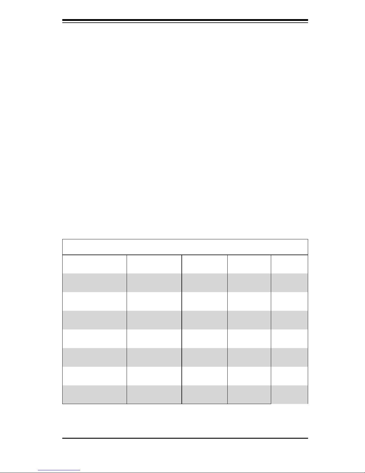
SC812L Chassis
Model CPU HDD I/O Slots
SC812L-420
SC812L-420C
SC812L-410
SC812L-520
SC812L-520C
SC812L-520U
DP Dual-core
Xeon
DP Dual-core
Xeon
DP Dual-core
Xeon
DP Dual-core
Xeon
DP Dual-core
Xeon
DP Dual-core
Xeon
3 Fixed
Hard Drives
3 Fixed
Hard Drives
3 Fixed
Hard Drives
3 Fixed
Hard Drives
3 Fixed
Hard Drives
3 Fixed
Hard Drives
1x FF, 1x LP 420W
1x FF 420W
1x FF, 1x LP 410W
1x FF, 1x LP 520W
1x FF 520W
2x FF, 1x LP 520W
Power
Supply
SC812LS-280U
DP Dual-core
Xeon
3 Fixed
Hard Drives
1-1
2x FF, 1x LP 280W

SC812L Chassis Manual
1-2
1-3 Where to get Replacement Components
Though not frequently, you may need replacement parts for your system. To en-
sure the highest level of professional service and technical support, we strongly
recommend purchasing exclusively from our Supermicro Authorized Distributors /
System Integrators / Resellers. A list of Supermicro Authorized Distributors / Sys-
tem Integrators /Reseller can be found at: http://www.supermicro.com. Click the
Where to Buy link.

1-3
Chapter 1: Introduction
1-4 Contacting SuperMicro
Headquarters
Address: SuperMicro Computer, Inc.
980 Rock Ave.
San Jose, CA 95131 U.S.A.
Tel: +1 (408) 503-8000
Fax: +1 (408) 503-8008
Email: marketing@supermicro.com (General Information)
support@supermicro.com (Technical Support)
Web Site: www.supermicro.com
Europe
Address: SuperMicro Computer B.V.
Het Sterrenbeeld 28, 5215 ML
's-Hertogenbosch, The Netherlands
Tel: +31 (0) 73-6400390
Fax: +31 (0) 73-6416525
Email: sales@supermicro.nl (General Information)
support@supermicro.nl (Technical Support)
rma@supermicro.nl (Customer Support)
Asia-Pacifi c
Address: SuperMicro, Ta i wan
4F, No. 232-1, Liancheng Rd.
Chung-Ho 235, Taipei County
Taiwan, R.O.C.
Tel: +886-(2) 8226-3990
Fax: +886-(2) 8226-3991
Web Site: www.supermicro.com.tw
Technical Support:
Email: support@supermicro.com.tw
Tel: 886-2-8228-1366, ext.132 or 139

SC812L Chassis Manual
Notes
1-4

Chapter 2: System Safety
Chapter 2:
System Safety
2-1 Overview
This chapter provides a quick setup checklist to get your chassis up and running.
Following the steps in order given should enable you to have your chassis setup and
operational within a minimal amount of time. This quick set up assumes that you
are an experienced technician, familiar with common concepts and terminology.
2-2 Warnings and Precautions
You should inspect the box the chassis was shipped in and note if it was damaged
in any way. If the chassis itself shows damage, fi le a damage claim with carrier
who delivered your system.
Decide on a suitable location for the rack unit that will hold that chassis. It should
be situated in a clean, dust-free area that is well ventilated. Avoid areas where
heat, electrical noise and electromagnetic fi elds are generated.
You will also need it placed near at least one grounded power outlet.
2-3 Preparing for Setup
The SC812L Chassis includes a set of rail assemblies, including mounting brackets
and mounting screws you will need to install the systems into the rack. Please read
this manual in its entirety before you begin the installation procedure.
2-4 Electrical Safety Precautions
Basic electrical safety precautions should be followed to protect yourself from harm
and the SC812L from damage:
l Be aware of the locations of the power on/off switch on the chassis as well
as the room’s emergency power-off switch, disconnection switch or electri-
cal outlet. If an electrical accident occurs, you can then quickly remove
power from the system.
2-1

SC812L Chassis Manual
2-2
l Do not work alone when working with high voltage components.
l Power should always be disconnected from the system when removing or
installing main system components, such as the serverboard, memory mod-
ules and the DVD-ROM and fl oppy drives (not necessary for hot swappable
drives). When disconnecting power, you should fi rst power down the
system with the operating system and then unplug the power cords from all
the power supply modules in the system.
l When working around exposed electrical circuits, another person who is fa-
miliar with the power-off controls should be nearby to switch off the power,
if necessary.
l Use only one hand when working with powered-on electrical equipment.
This is to avoid making a complete circuit, which will cause electrical shock.
Use extreme caution when using metal tools, which can easily damage any
electrical components or circuit boards they come into contact with.
l Do not use mats designed to decrease electrostatic discharge as protection
from electrical shock. Instead, use rubber mats that have been specifi cally
designed as electrical insulators.
l The power supply power cord must include a grounding plug and must be
plugged into grounded electrical outlets.
l Serverboard Battery: CAUTION - There is a danger of explosion if the
onboard battery is installed upside down, which will reverse its polarities
This battery must be replaced only with the same or an equivalent type
recommended by the manufacturer. Dispose of used batteries according to
the manufacturer’s instructions.
l DVD-ROM Laser: CAUTION - this server may have come equipped with a
DVD-ROM drive. To prevent direct exposure to the laser beam and hazard-
ous radiation exposure, do not open the enclosure or use the unit in any
unconventional way.
2-5 General Safety Precautions
l Keep the area around the chassis clean and free of clutter.
 Loading...