

Page 1
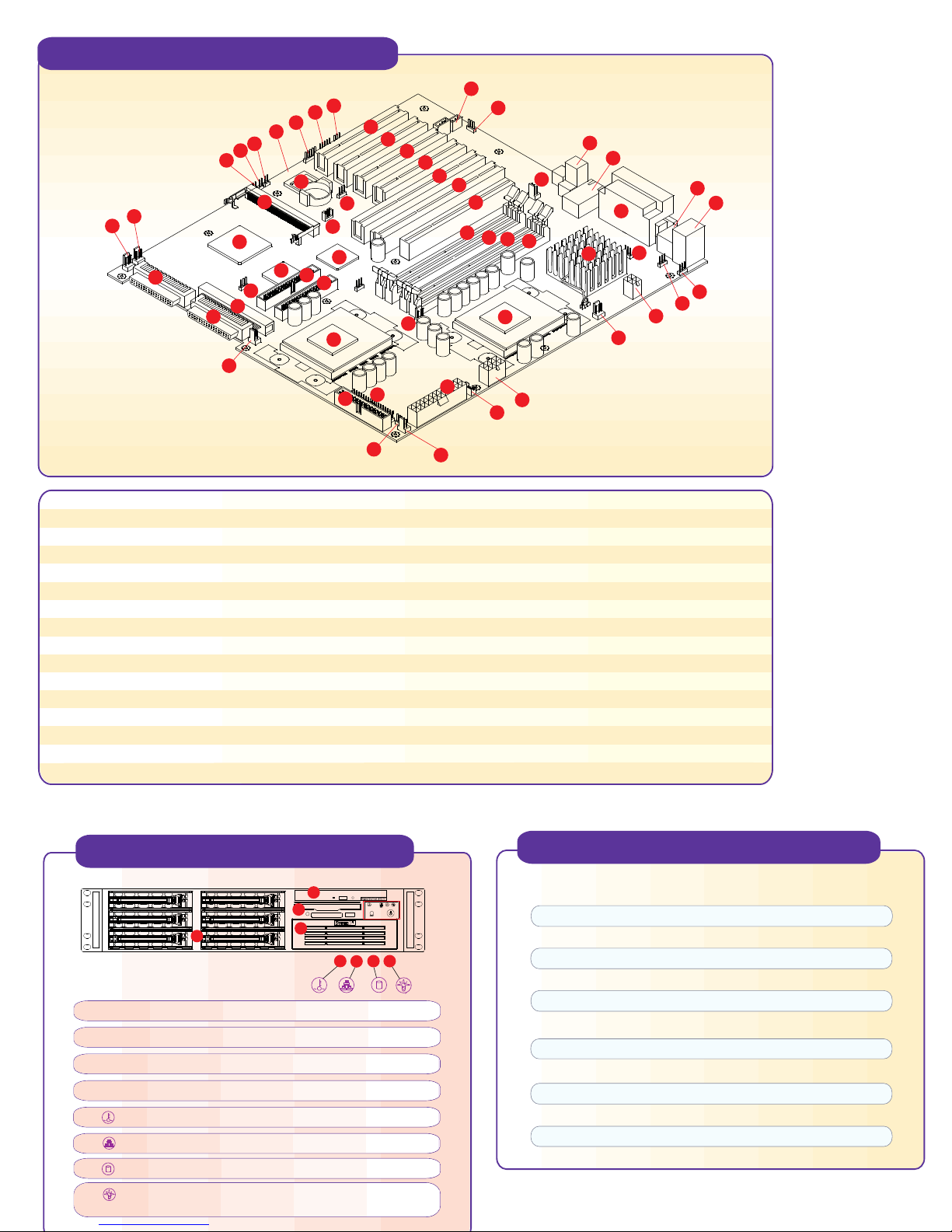
Motherboard Components
56
57
58
1
4
5
6
2
10
11
12
13
3
9
15
16
18
14
20
17
53
7
8
19
21
23
24
55
54
52
51
50
49
48
47
46
45
30
27
42
44
43
22
29
28
41
40
38
39
36
35
32
31
37
34
33
25
1 System Board
2 BIOS
3 RAID Port
4 JWOR
5 JPA1 SCSI Terminator
6 JPA2 SCSI Terminator
7 JP34
8 WOL
9 AIC-7899
10, 11 CH FAN1, CH FAN2
12 Ultra160 LVD SCSI CHA
13 Ultra160 LVD SCSI CHB
14 Ultra SCSI CHB
15 ICH2
16, 17 IDE#1, IDE#2
18 JBT1
Two continuity memory modules must be installed in Bank 1 if only one pair of RAMBUS modules is installed in Bank 0.
*
19 P64H
20 CH FAN3
21, 22 CPU#1, CPU#2
23 JF1
24 Floppy
25 JP38
26 CH FAN4
27 ATX Power
28 JP37 Power Fail Signal Conn.
29 J24 (8-pin 12V conn.)
30, 31 CPU FAN1, CPU FAN2
32 J23 (4-pin 12V conn.)
33 JP39
34 JPWAKE
35 JP36
36 MCH
Front Panel Functions
2
3
1
4
5
8
6
7
26
37 Mouse and Keyboard Ports
38 2 USB Porta
39 Parallel Port, COM1, COM2
40 LAN
41 AC97' Audio CODEC
42 OH FAN
43,44 Rambus Bank 0 *
45,46 Rambus Bank 1*
47 AGP Pro Slot
48,49 2 64-bit PCI (66MHz)
50,51,52,53 4 32-bit PCI (33MHz)
54 JP35
55 CD1, CD2
56 JP4
57 J20
58 J29
P4DC6+ Quick Reference
Jumper Description Default Setting
JBT1 CMOS clear Pins 1-2 (Normal)
JP2, JP2A1 Manufacturer setting Pins 1-2 (Auto)
JPA1, A2 SCSI termination Open (Enabled)
JPA3 64-bit PCI speed select Open (66 MHz)
1. 6 SCA Ultra160 hot-swap drive bays
2. 1 slim CD-ROM
3. Floppy drive
4. 1 x 5.25" drive bay
5. Overheat: Indicates an overheat condition in the system
6. NIC1: Indicates network activity on LAN1 when flashing
JP4 Onboard audio Pins 1-2 (Enabled)
JP35 LAN enable/disable Pins 1-2 (Enabled)
JP34 SCSI enable/disable Pins 1-2 (Enabled)
JP36 Manufacturer setting Pins 1-2 (Enabled)
JP38 Third power supply fail alarm Open (Disabled)
JP39 USB wake up Pins 1-2 (Enabled)
JPWAKE Keyboard wake up Pins 1-2 (Disabled)
7. HDD: Indicates IDE channel activity.
8. Power: Indicates power is being supplied to the system's
power supply units
Page 2
Rear Panel Functions
1
2
1. AC Power connector
2. PS/2 Mouse and Keyboard ports
3. 2 USB ports
4. COM 1
5. COM 2
6. Parallel port
7. Intel 82559 LAN port
8. AC'97 audio CODEC
9. 7 low-profile I/O expansion slots
6
3
5
4
7
8
9
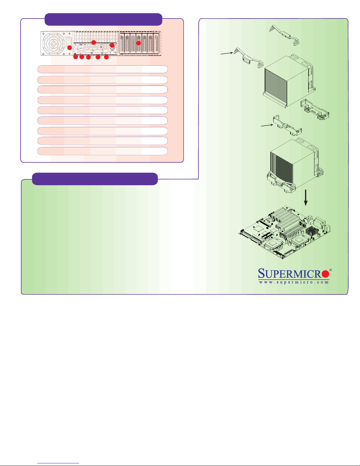
Cooling Fan Installation
Warning !
CPU Heatsink Installation Procedures
(For Supermicro SuperServer 2U Systems)
Clip
CPU heatsink retention
Due to the fact that adequate air flow and proper thermal control are very critical in
maintaining 2U system's stability and performance, it is imperative that the proper
installation procedures listed below be followed in order to maximize system performance.
This is especially critical for 2U dual processor servers with speeds of 1 GHz and above.
1) Only those CPU heatsinks that are provided by Supermicro should be used.
2) Apply a small amount of silicon compound on the CPU's die.
3) Place the CPU heatsink on top of the CPU.
4) Place the heatsink spring on top of the CPU heatsink and secure the clip of the spring into its notch.
(Make sure the clip position is the same as in the picture shown)
To protect the system and components, it is essential that you reinstall the top panel after you have finished working on the system.
CPU
CPU
 Loading...