

Page 1
Motherboard Components
1 System Board
2 Ultra160 SCSI CH B (P3TSSR only)
3 Ext. Ultra160 SCSI CH B (P3TSSR only)
4 JPA2
5 AIC-7899W (P3TSSR only)
6 JPA1
7 Ultra160 SCSI CH A (P3TSSR only)
8 JL1
9 JBT1
10 JWOR
11 WOL
12 JP32
13 IDE1
14 IDE2
15 Floppy
16 USB2, USB3
17 JP36
18 OH Fan
19 Blower Fan
20 OH Fan, CH Fan1
21, 22, 23,24 PCI1, 2, 3, 4
25 BIOS FWH
26 ICH2
27 4xAGP
28, 29, 30 DIMM 0, 1, 2
31 PW LED
32 IR
33 JF1
34 GMCH
35 JP11
36 JP12
37 ATX Power
38 CPU 1
39 CPU Fan
40 JPWAKE
41 COM2
42 Mouse and Keyboard Conn.
43 USB
44 COM1
45 VGA
46 LAN1
47 LAN2
48 JP35
49 JP31
29
46
11
30
28
1
17
35
39
10
32
6
8
9
38
37
36
19
34
48
43
42
45
44
41
12
47
49
31
20
33
40
26
* SuperServer 5011H: P3TSSR Motherboard
* SuperServer 5011E: P3TSSE Motherboard
25
27
24
23
21
22
3
2
4
5
7
13
14
15
18
16
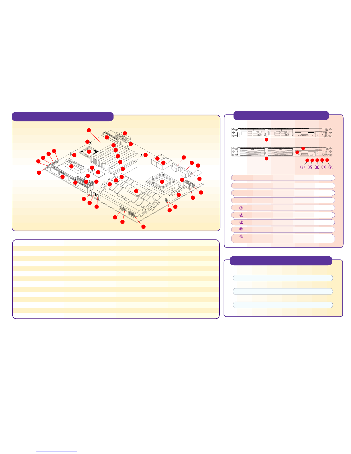
Front Panel Functions
5011E
5011H
1
P3TSSE Quick Reference
Jumpers Description Default Setting
JBT1 CMOS Clear Pins 1-2 (Normal)
JP11/12 Front Side Bus Speed Both: Pins 1-2 (Auto)
JP31 LAN2 Enable/Disable Closed (Enabled)
JP35 LAN1 Enable/Disable Closed (Enabled)
JP36 Speaker/Watchdog Enable Closed (Speaker)
JPWAKE Keyboard Wake-Up Pins 1-2 (Disabled)
1. Hot-plug SCSI hard drive, SCSI ID 1,0
2. 3.5 IDE drive bay
3. CD-ROM/diskette drive assembly
4. Floppy drive
5. Overheat: Indicates an overheat condition in the system
6. NIC2: Indicates network activity on LAN2 when flashing
7. NIC1: Indicates network activity on LAN1 when flashing
8. HDD: Indicates IDE channel activity.
9. Power: Indicates power is being supplied to the system's
power supply units
R
SUPER
R
SUPER
2
4
3
5
6
7
8
9
Page 2
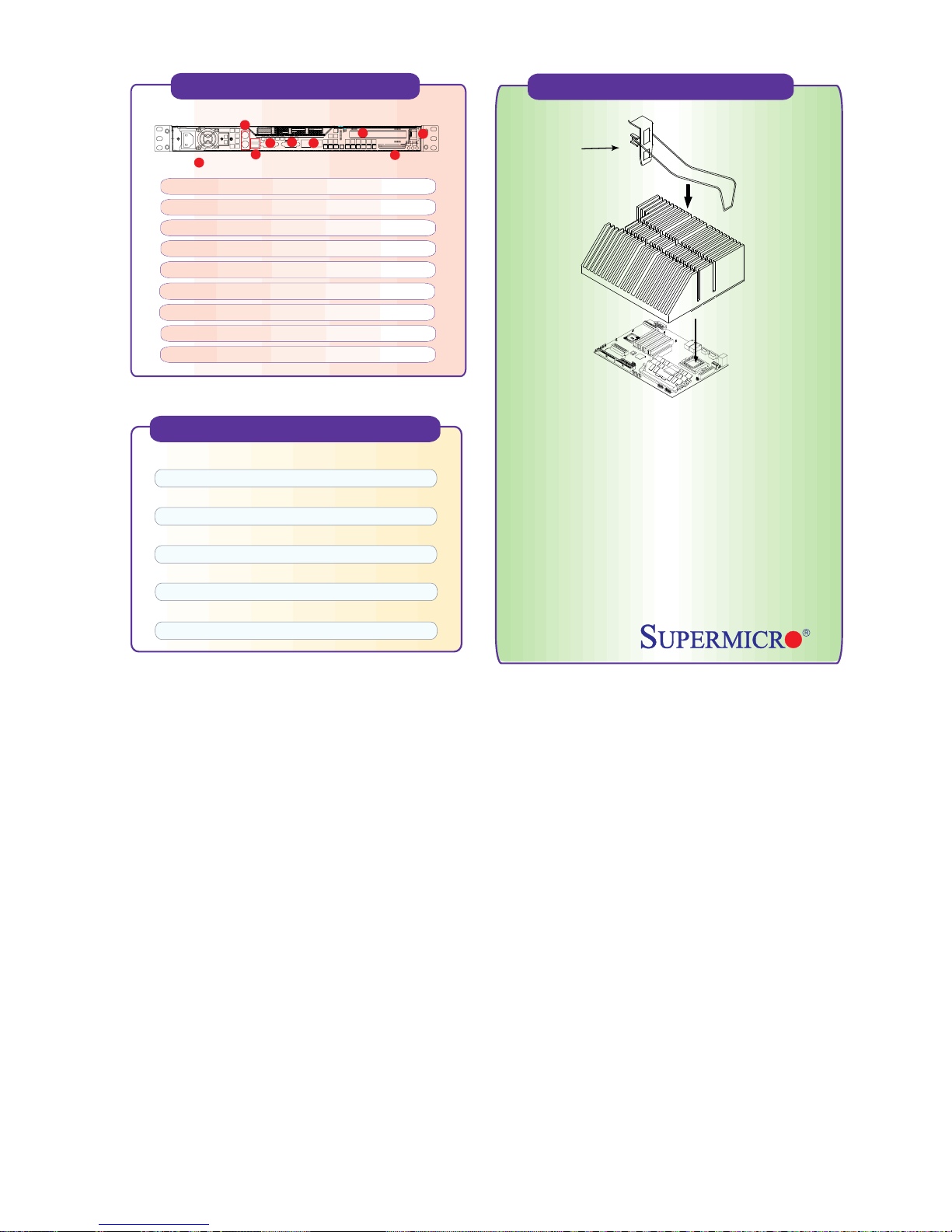
Rear Panel Functions
5011H, 5011E
1. AC Power connector
2. PS/2 Mouse and Keyboard ports
3. 2 USB ports
4. 2 COM ports (1 internal)
5. 1 VGA port
6. 2 x Intel 82559 LAN ports
7. 64/32-bit Expansion slot
8. External High Density SCSI Connector (5011H only)
9. PCI Card Release Latch
2
5
4
1
3
6
7
8
P3TSSR Quick Reference
Jumpers Description Default Setting
JBT1 CMOS Clear Pins 1-2 (Normal)
JPA1 SCSI CH A Termination Open (Terminated)
JPA2 SCSI CH B Termination Open (Terminated)
JP11/12 Front Side Bus Speed Both: Pins 1-2 (Auto)
JP31 LAN2 Enable/Disable Closed (Enabled)
JP34 SCSI Enable/Disable Pins 1-2 (Enabled)
JP35 LAN1 Enable/Disable Closed (Enabled)
JP36 Speaker/Watchdog Enable Closed (Speaker)
JPWAKE Keyboard Wake-Up Pins 1-2 (Disabled)
Cooling Fan Installation
9
Warning !
CPU Heat Sink Installation Procedures
(For Supermicro SuperServer 1U Systems)
Due to the fact that adequate air flow and proper thermal control are
very critical in maintaining 1U system's stability and performance, it is
imperative that the proper installation procedures listed below be
followed in order to maximize system performance. This is especially
critical for 1U Dual Processor Servers with speeds of 1 GHz and above.
1) Only those CPU heat sinks that are provided by Supermicro should be used.
2) Apply a small amount of silicon compound on the CPU's die.
3) Place the CPU heat sink on top of the CPU.
4) Place the heat sink spring on top of the CPU heat sink and secure the clip of
the spring into its notch. (Make sure the clip position is the same as the
picture shown above.)
clip
CPU1
To protect the system and components and ensure proper cooing, it is essential that you reinstall the top panel after you have finished working on the system.
 Loading...