

Page 1
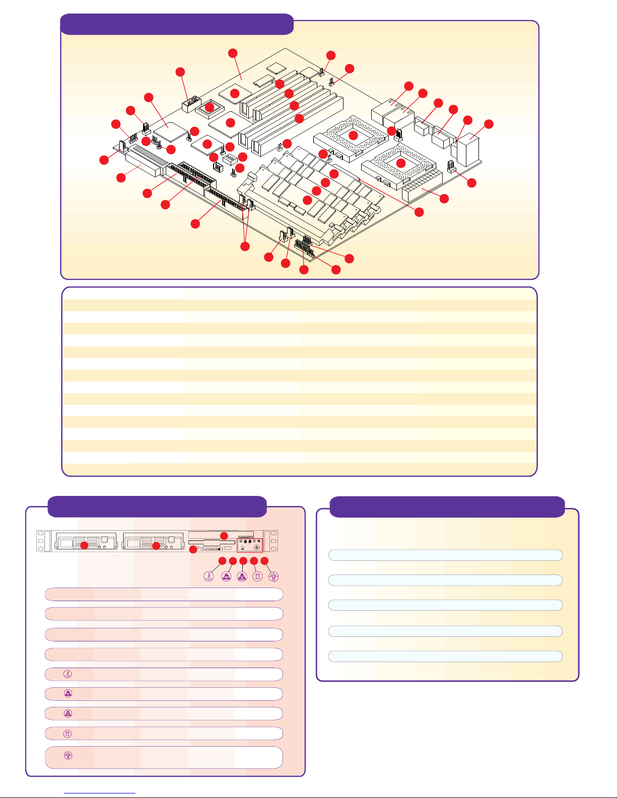
Motherboard Components
1
5
6
7
8
9
11
12
13
16
10
14
15
1 System Board
2 ATI Rage XL
3 BIOS
4 South Bridge
5 COM2
6 Super I/O
7 WOL
8 SLED1
9 JBT1
10 WOM
11 Overheat Fan
12 Ultra160 LVD SCSI
13 IDE#2 Connector
14 Floppy Connector
15 IDE #1 connector
16 J210
Note: E.C.C. registered memory type must be installed.
*
2
3
4
36
37
39
40
17 Chassis Fan
18 Blower Fan
19 Chassis Fan
20 JF1
21 JP61
22 J105/J106 (USB4/USB3)
23 Mouse and Keyboard Connectors
24 2 USB
25 COM1
26 VGA
27 NIC1
28 NIC2
29 JP24
30 JP8
31 PCI 2
32 PCI 1
30
29
31
32
33
34
35
38
17
18
19
41
45
46
20
47
43
44
22
21
28
27
26
25
24
51
48
49
42
23
50
33 PCI64#2
34 PCI64#1
35 JP13
36 AIC-7892
37 JP1
38 SW1
39 JP11, JP12
40 JP7
41 JP2
42 North Bridge
43, 44, 45, 46 DIMM 0, 1, 2, 3
47 CPU 1
48 CPU 2
49 ATX Power
51 CPU Fan
52 CPU Fan
Front Panel Functions
1
1. Hot-plug SCSI hard drive, SCSI ID 0
2. Hot-plug SCSI hard drive, SCSI ID 1
3. CD-ROM/disketle drive assembly
4. Floopy Drive
5. Overheat: Indicates an overheat condition in the system
6. NIC2: Indicates network activity on LAN2 when flashing
7. NIC1: Indicates network activity on LAN1 when flashing
8. HDD: Indicates IDE channel activity.
9. Power: Indicates power is being supplied to the system's
power supply units
2
4
P3TDLR+ Quick Reference
3
5
789
6
Jumpers Description Default Setting
JBT1 CMOS Clear Pin 1-2 (Normal)
JP1 SCSI Pin 1-2 (Enabled)
JP2 Front Side Bus Speed Pin 1-2 (CPU Select)
JP7 Overheat Alarm Closed (Enabled)
JP8 NIC1 Enable/Disable Open (Enabled)
JP11 Power Supply Fail Pin 4 (Reset)
JP12 Power Supply Fail Closed (Enabled)
JP13 Speed for 64-bit PCI Closed (33 MHz)
JP24 NIC2 Enable/Disable Open (Enabled)
JP62 Onboard VGA Pin 1-2 (Enabled)
J210 Watchdog Reset Open (Enabled)
Page 2
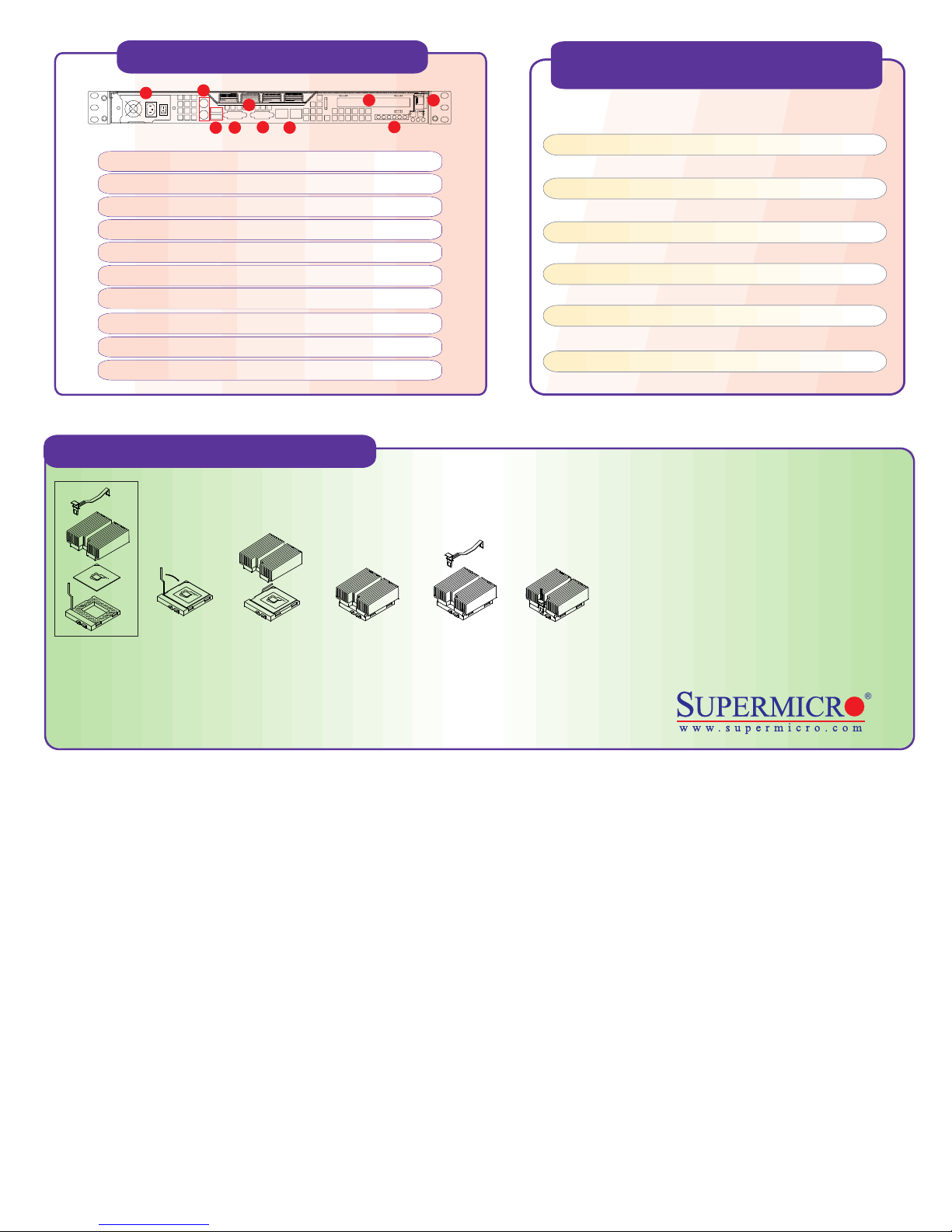
Rear Panel Functions
CPU Core/Bus Ratio Selection
(DIP Switch 1)
1
1. AC Power connector
2. PS/2 Mouse and Keyboard port
3. 2 USB ports
4. 2 COM ports ( 1 internal)
5. 1 VGA port
6. 1 Parallel port
7. 2 x Intel 82559 LAN port
8. 64/32-bit Expansion slot
9. External SCSI port
10. PCI Card Release Latch
2
6
5
4
3
7
8
10
9
CPU
600/450
667/500
733/550
800/600
866/650
933/700
1G/750
1.06G/800
1.13G/850
1.20G/900
1.26G/950
1.4G/1G
Cooling Fan Installation
= >
1 2 3 4 5
1) Only those CPU heat sinks that are provided by Supermicro should be used.
2) Apply proper amount of silicon compound on the CPU's die.
3) Place the CPU heat sink on top of the CPU.
4) Place the heat sink spring on top of the CPU heat sink and lock the backside of the spring into its notch.
5) Lock the front side of the heat sink spring into its notch.
SW1
#1
OFF
ON
OFF
ON
OFF
ON
OFF
ON
ON
OFF
OFF
ON
SW1
#2
ON
OFF
OFF
ON
ON
OFF
OFF
ON
OFF
OFF
ON
ON
SW1
#3
OFF
OFF
OFF
ON
ON
ON
ON
OFF
ON
ON
ON
OFF
SW1
#4
ON
ON
ON
OFF
OFF
OFF
OFF
OFF
ON
ON
ON
ON
Warning !
CPU Heat Sink Installation Procedures
(For Supermicro SuperServer 1U Systems)
Due to the fact that adequate air flow and
proper thermal control are very critical in
maintaining 1U system's stability and
performance, it is imperative that the proper
installation procedures listed below be
followed in order to maximize system
performance. This is especially critical for 1U
Dual Processor Servers with speeds of 1
GHz and above.
To protect the system and components, it is essential that you reinstall the top panel after you have finished working on the system.
 Loading...