

Page 1
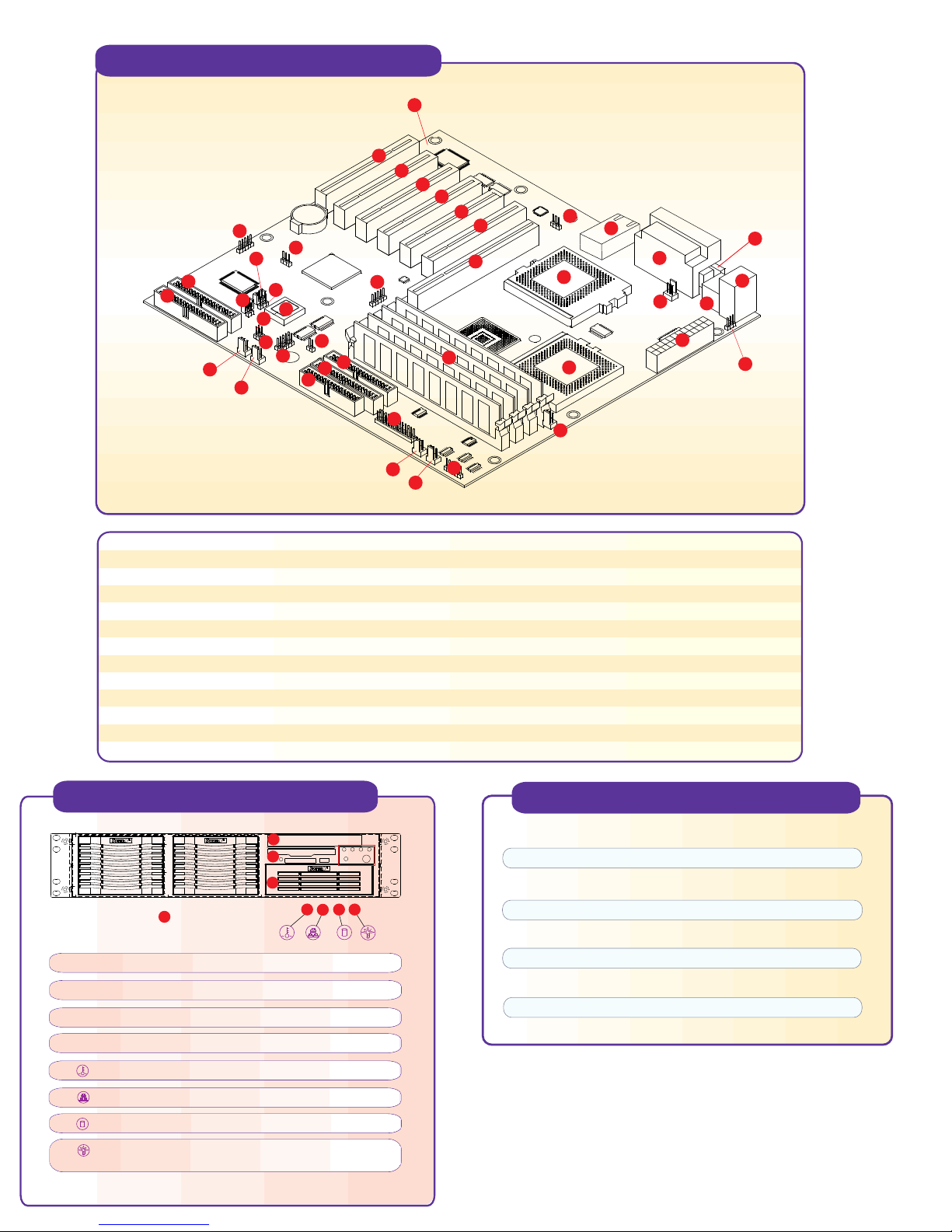
Motherboard Components
1
43
42
41
2
3
4
8
9
10
6
5
7
12
19
11
15
13
17
16
14
18
40
39
38
37
24
36
35
34
28
26
32
29
27
33
31
30
1 System Board
2 J18
3 JBT1
4 WOL1
5 WOM1
6 J17
7 BIOS
8 IDE RAID #1
9 IDE RAID #2
10 Chassis Fan2
11 CPU2 Chssis Fan
12 JL1
13 USB3,USB4
Front Panel Functions
2
3
4
1
1. 6 x 3.5" IDE drive bays
2. 1 Slim CD-ROM (optional)
3. 1 x Floppy Drive
20
21
23
22
14 JP8: I2C
15 JP7
16 Floppy Connector
17 IDE #2
18 IDE #1
19 JP6
20 JF1, JP9: Front Control Panel Conn.
21 CPU1 Chassis Fan
22 Chassis Fan 1/0 H
23 J19: 6-pin Power Conn.
24 DIMM 0,1,2,3
25 CPU1 Fan
26 CPU2 Fan
5
8
6
7
25
27 CPU#1
28 CPU#2
29 J10: 24-pin ATX PWR Conn.
30 JP2: JPWAKE
31 Mouse and Keyboard Connectors
32 USB1, USB2
33 COM 1, COM 2
34 Printer Port
35 LAN1
36 JPL1L
37 4xAGP Pro
38,39,40,41,42 32-bit PCI
43 ACR
P3TDDE Quick Reference
Jumper Description Default Setting
JBT1 CMOS Clear Pin 1-2 (Normal)
JPWAKE Keyboard Wake-Up Pin 1-2 (Disabled)
JPL1 LAN Enable/Disable Pin 1-2 (Enabled)
JP7 CPU/Chassis Fan RPM Detection Pin 1-2 (Disabled)
JP6 OH/Chassis Fan Pin 1-2 (Over Heat)
J17 Onboard IDE RAID Pin 1-2 (Enabled)
Onboard IDE RAID Pin 2-3 (Disabled)
4. 1 x 5.25" drive bay
5. Overheat: Indicates an overheat condition in the system
6. NIC1: Indicates network activity on LAN1 when flashing
7. HDD: Indicates IDE channel activity.
8. Power: Indicates power is being supplied to the system's
power supply units
Page 2
Rear Panel Functions
2
1
1. AC Power connector
2. PS/2 Mouse and Keyboard port
3. 2 USB ports
4. COM 1
5. COM 2
6. 1 Parallel port
7. 1 Intel 82559 LAN port
8. 7 Low-Profile 64/32-bit Expansion slot
6
5
4
3
7
Installing 5.25" Drive Bay Rail
8
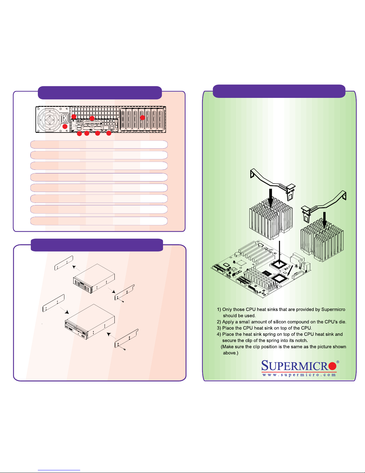
Cooling Fan Installation
Warning !
CPU Heat Sink Installation Procedures
(For Supermicro SuperServer 2U Systems)
Due to the fact that adequate air flow and proper thermal control
are very critical in maintaining 2U system's stability and
performance, it is imperative that the proper installation
procedures listed below be followed in order to maximize system
performance. This is especially critical for 2U Dual Processor
Servers with speeds of 1 GHz and above.
Remove the drive bay cover by pressing the tab. Install the rails
onto the new component and then the new component into the
drive bay until you hear a clicking sound from the tab.
 Loading...