

Page 1

C7Z270-CG
ENGLISH
繁體中文
简体中文
日本語
(
한국어
QUICK REFERENCE GUIDE
Revision 1.0
Page 2
C7Z270-CG QUICK REFERENCE GUIDE Product Safety Information
Standardized Warning Statements
Motherboards
About Standardized Warning Statements
The following statements are industry standard warnings, provided to warn the user of situations which can potentially
cause a bodily injury. Should you have questions or experience difculty, contact Supermicro's Technical Support De-
partment for assistance. Only certied technicians should attempt to install or congure components.
Read this section in its entirety before installing or conguring components in the Supermicro chassis.
Battery Handling
Warning!
There is a danger of explosion if the battery is replaced incorrectly. Replace the battery only with the same or an equiva-
lent type recommended by the manufacturer. Dispose of used batteries according to the manufacturer's instructions.
警告
電池更換不當會有爆炸危險。請使用製造商建議之相同或功能相當的電池更換原有電池。請按照製造商的說明指示處理
廢棄舊電池。
警告
电池更换不当会有爆炸危险。请只使用同类电池或制造商推荐的功能相当的电池更换原有电池。请按制造商的说明处理
废旧电池。
電池の取り扱い
電池交換が正しく行われなかった場合、破裂の危険性があります。 交換する電池はメーカーが推奨する型、または同等のも
のを使用下さい。 使用済電池は製造元の指示に従って処分して下さい。
경고!
배터리가 올바르게 교체되지 않으면 폭발의 위험이 있습니다. 기존 배터리와 동일하거나 제조사에서 권장하는 동등한
종류의 배터리로만 교체해야 합니다. 제조사의 안내에 따라 사용된 배터리를 처리하여 주십시오.
Note: For complete product safety information, refer to http://www.supermicro.com/about/policies/safety_information.cfm.
Page 3

C7Z270-CG QUICK REFERENCE GUIDE
限用物質含有情況標示聲明書
Motherboard
C7Z270-CG
(Motherboard)
Equipment name
Type designation (Type)
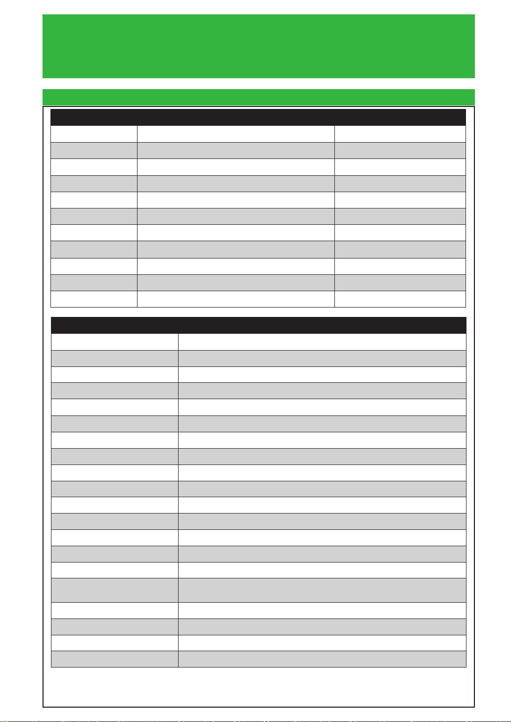
Restricted substances and its chemical symbols
Declaration of the Presence Condition of the Restricted Substances Marking
Note 1:“Exceeding 0.1 wt %” and “exceeding 0.01 wt %” indicate that the percentage content of the restricted substance exceeds the
reference percentage value of presence condition.
Note 2:“○” indicates that the percentage content of the restricted substance does not exceed the percentage of reference value of presence.
Note 3:The “−” indicates that the restricted substance corresponds to the exemption.
限用物質含有情況標示聲明書
Declaration of the Presence Condition of the Restricted Substances Marking
限用物質含有情況標示聲明書
設備名稱:主機板 /
,型號(型式):
限用物質及其化學符號
單元Unit
鉛Lead
(Pb)
Mercury
汞
(Hg)
Cadmium
鎘
(Cd)
六價鉻
Hexavalent
chromium
(Cr+6)
主機板
備考1.〝超出0.1 wt %〞及〝超出0.01 wt %〞係指限用物質之百分比含量超出百分比含量基準
值。
-
○ ○ ○ ○ ○
多溴聯苯
Polybrominated
biphenyls
(PBB)
多溴二苯醚
Polybrominated
diphenyl ethers
(PBDE)
備考2.〝○〞係指該項限用物質之百分比含量未超出百分比含量基準值。
備考3.〝-〞係指該項限用物質為排除項目。
Page 4
C7Z270-CG QUICK REFERENCE GUIDE BIOS POST Code
AMI BIOS POST Codes
About AMI BIOS POST Codes
The table below lists some of AMI BIOS POST codes for C7Z270-CG. For more information, refer to https://www.
supermicro.com.tw/manuals/other/AMI_BIOS_POST_Codes_for_Grantley_Motherboards.pdf.
Code Description
0x32 CPU post-memory initialization is started
0x55 No Memory detected or memory failed
0x63 CPU DXE initialization is started
0x69 North Bridge DXE initialization is started
0x70 South Bridge DXE initialization is started
0x92 PCI Bus initialization is started
0x99 Super IO Initialization
0x9A USB initialization is started
0xA0 IDE initialization is started
0xA9 Boot into BIOS setup menu
0xAE Legacy Boot event
0xB2 Legacy Option ROM Initialization
0xB4 USB hot plug
0xD6 No VGA device
0xD7 No Keyboard plug in
0xF2 Recovery process started
0xF9 Recovery capsule is not found
Page 5
C7Z270-CG QUICK REFERENCE GUIDE Notes
Notes
Page 6

UPERMICR
S
R
C7Z270-CG
Quick RefeRence Guide Rev. 1.0
Motherboard Layout and Features
I/O BACK PANEL
AUDIO FP
JI2C1/JI2C2
ON :ENABLE
OFF:DISABLE
JL2
JPCIE1 JPCIE3
JSTBY1:
5V STBY POWER
JI2C2
JI2C1
JBR1
ON:BIOS RECOVERY
OFF:NORMAL
JBR1
USB2/3
USB4/5
USB6/7
USB 12/13 (3.0)
JL1
JL1:
CHASSIS
INTRUSION
JTPM1:
PWR
LED LED
TPM/PORT80
HDD
JTPM1
NIC
1
X
OH/FF X
JLED1:
3 PIN POWER LED
RST
1
PWR
LED1
C
ON
A
JF1
JWD1
COM1
JPCIE2
CPU SLOT1 PCI-E 3.0 X4 (IN X16)
PCH SLOT2 PCI-E 3.0 X1
PCIE M.2 CONNECTOR 1
JLED1
JWD1:
1-2:RST
2-3:NMI
WATCH DOG
LED4
U.2 CONNECTOR 1
U.2 CONNECTOR 2
CPU SLOT3 PCI-E 3.0 X8 (IN X16)
PCH SLOT4 PCI-E 3.0 X1
JD1:
SPEAKER:1-4
BUZZER:3-4
LED3
A C
A C
LED19
LED18
A
C
LED20
I-SATA4
JSD1
I-SATA5
JSD1:
SATA DOM PWR
JPCIE4
JPAC1
JPME2
2-3:ME MANUFACTURING MODE
1-2:NORMAL
C7Z270-CG
REV:1.00
JPAC1:AUDIO
1-2:ENABLE
2-3:DISABLE
JSPDIF_OUT
DESIGNED IN USA
JPCIE5
PCH SLOT5 PCI-E 3.0 X1
JPME2:
JPCIE6
CPU SLOT6 PCI-E 3.0 X16
SYS_FAN3
FAN5
HD AUDIO
USB 10/11 (3.1)
LAN
USB 8/9 (3.1)
JPL1:LAN
1-2:ENABLE
2-3:DISABLE
DVI
HDMI/DP
KB/MOUSE
USB 0/1
JPL1
JPW2
CPU_FAN2
FAN4
LGA 1151
7th/6th Gen
B1
+
BAR CODE
MAC CODE
JD1
SP1
BIOS LICENSE
JBT1
CMOS CLEAR
JBT1
A
C
LED17
PCIE M.2 CONNECTOR 2
FAN3
I-SATA2
I-SATA0
I-SATA1
SYS_FAN2
I-SATA3
A
LED2
MH7
JPW1
Intel® CoreTM i7/i5/i3
Series CPU
POWER BUTTON
S4
RESET BUTTON
FAN2
FAN1
CPU_FAN1
DIMMA1
DIMMA2
DIMMB1
DIMMB2
CLEAR CMOS
S12
SYS_FAN1
S8
= mounting hole
= for I/O cover
Page 7
Package contents
• One (1) Supermicro Motherboard
• Four (4) SATA Cables, One (1) I/O Shield
• One (1) Quick Reference, One (1) Driver CD
Jumpers and Connectors
Jumpers
Jumper Description Default
CLEAR CMOS Clear CMOS Switch Push Button Switch
JBR1 BIOS Recovery Switch Pins 1-2 (Disable)
JBT1 Clear CMOS (on board) Short pads to clear CMOS
JI2C1/JI2C2 SMB to PCI Slots On (Enabled)
JPAC1 Audio Enable Pins 1-2 (Enabled)
JPL1 LAN1 Enable/Disable Pins 1-2 (Enabled)
JPME2
JWD1 Watch Dog Function Enable Pins 1-2 (RST)
POWER BUTTON Internal Power Button Push Button Switch
RESET BUTTON Onboard System Reset Button Push Button Switch
Intel® Manufacturing Mode
Pins 1-2 (Normal)
Connectors
Connector Description
AUDIO FP Front Panel Audio Header
B1 Onboard Battery
COM1 COM1 Port Header
I-SATA0~5
JD1 Speaker/buzzer (Pins 1~4: External Speaker, Pins 3~4: Buzzer)
JF1 Front Panel Control Header
JL1 Chassis Intrusion Header
JLED1 Power LED Indicator Header
JPW1 24-pin ATX Main Power Connector (Required)
JPW2 +12V 8-pin CPU power Connector (Required)
JSD1 SATA DOM (Disk On Module) Power Connector
JSPDIF_OUT Sony/Philips Digital Interface Format (S/PDIF) Out Header
JSTBY1 Standby Power Header
JTPM1 Trusted Platform Module (TPM) Header
PCI-E M.2 CONNECTOR 1, 2* PCI-E M.2 Connectors 1 and 2, small form factor devices and other portable
U.2 CONNECTOR 1, 2* U.2 Connector 1 and 2, for 2.5” SSD Drives
USB 2/3, USB 4/5, USB 6/7 Front Panel Accessible USB 2.0 Headers 2/3, 4/5. 6/7
USB 12/13 (3.0) Front Panel Accessible USB 3.0 Header 12/13
SYS FAN 1,2,3 CPU FAN 1,2 System/CPU Fan Headers
(Intel® Z270) Serial ATA (SATA 3.0) Ports 0~5 (6Gb/sec)
devices for High speed NVMe SSDs
*PCIE M.2 Connector 1 shares with U.2 Connector 1. (When M.2 device is plugged into PCIE M.2 Connector 1, U.1 connector 1 will be automatically disabled.)
*PCIE M.2 Connector 2 shares with SATA4/5. (When M.2 device is plugged into PCIE M.2 Connector 2, SATA4/5 will be automatically disabled.)
Page 8
ContaCt InformatIon
• www.supermicro.com (Email: support@supermicro.com)
• Manuals: http://www.supermicro.com/support/manuals
• Drivers & Utilities: ftp://ftp.supermicro.com
• Safety: http://www.supermicro.com/about/policies/safety_information.cfm
LED Indicators
LED indicators
LED Description Color/State Status
LED1 Onboard Standby PWR LED Green: Solid on Power On
LED2 M.2 connector 2 SSD ACT LED Green: Solid on M.2 device connected
LED3 M.2 connector 1 SSD ACT LED Green: Solid on M.2 device connected
LED4 Status Code LED Digital Readout See manual
CPU & Memory Support
CPU & Memory Support
The C7Z270 -CG supports a 6th and 7th generation Intel® CoreTM i7/i5/i3 processor, up to 64GB of Unbuffered (UDIMM)
non-ECC DDR4 memory, up to 3733 MHz (OC) in four 288-pin memory slots. Populating these DIMM slots with
a pair of memory modules of the same type and same size will result in interleaved memory, which will improve
memory performance.
Note: 1) For memory optimization, use only DIMM modules that have been validated by Supermicro. For the latest memory updates, please
refer to our website at http://www.supermicro.com/products/motherboard.
2) Always connect the power cord last, and always remove it before adding, removing or changing any hardware components.
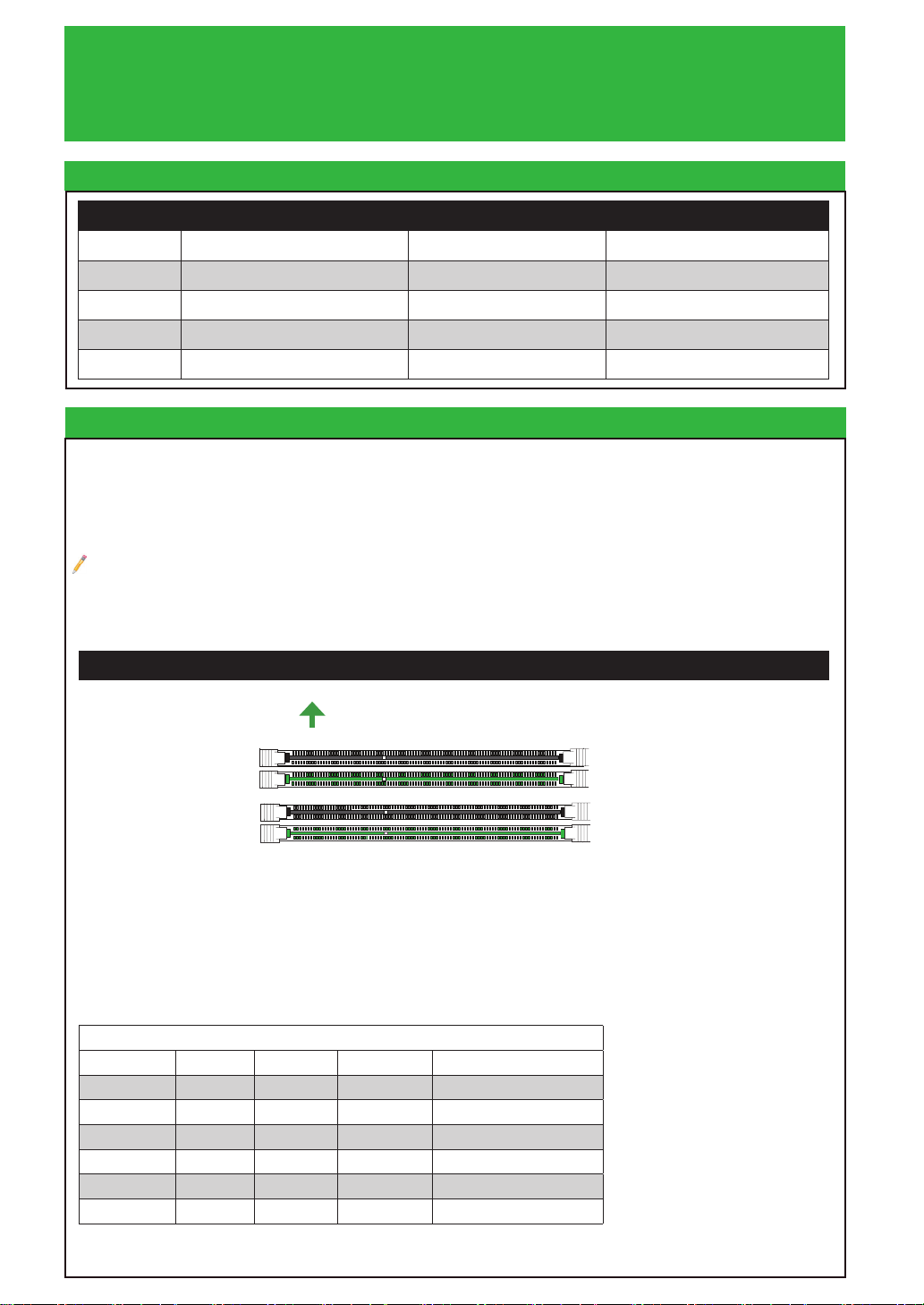
DIMM Memory Installation
Towards the CPU
DIMMA1 (Black Slot)
DIMMA2 (Green Slot)
DIMMB1 (Black Slot)
DIMMB2 (Green Slot)
Memory Population Guidelines
When installing memory modules, the DIMM slots should be populated in the following order: DIMMA2, DIMMB2,
then DIMMA1, DIMMB1.
• Always use DDR4 DIMM modules of the same size, type and speed.
• Mixed DIMM speeds can be installed. However, all DIMMs will run at the speed of the slowest DIMM.
Recommended Population (Balanced)
DIMMB2 DIMMA2 DIMMB1 DIMMA1 Total System Memory
4GB 4GB 8GB
4GB 4GB 4GB 4GB 16GB
8GB 8GB 16GB
8GB 8GB 8GB 8GB 32GB
16GB 16GB 32GB
16GB 16GB 16GB 16GB 64GB
Page 9

Notes
on
OH/Fan Fail
1516
• Graphics shown in this quick reference guide are for illustration only. Your components may or
may not look exactly the same as drawings shown in this guide.
• Refer to Chapter 2 of the User Manual for detailed information on jumpers, connectors, LED
indicators, memory support and CPU/motherboard installation instructions.
CPU Installation
Front Panel Control (JF1)
Power LED
HDD LED
NIC1 LED
Heatsink Installation
Mounting Hole
Add
thermal paste
Motherboard
Vcc
Vcc
Vcc
Heatsink
with Fan
MNL-1909-QRG-100
X
LED
X
Ground
Ground
2
X
Vcc
X
Reset
Reset Button
Power Butt
PWR
1
Back Panel I/O Connectors
A. PS/2 Keyboard/Mouse Port G. Gb LAN Port 1 M. Surround Out
B. USB 2.0 Port 0 H. USB 3.1 Port 8 N. S/PDIF Out
C. USB 2.0 Port 1 I. USB 3.1 Port 9 O. Line In
D. Display Port J. USB 3.1 Port 10 P. Line Out
E. HDMI Port K. USB 3.1 Port 11 (Type C) Q. Mic In
F. DVI Port L. Center/LFE Out
G
H
I
D
F
E
C7Z270-CG
A
B
C
L
J
K
O
P
Q
M
N
© 2017 Supermicro Computer Inc. All rights reserved. Reproduction of this document whether in part or in whole is strictly prohibited without Super-
micro's written consent. All Trademarks are property of their respective entities. All information provided is deemed accurate at the time of printing;
however, it is not guaranteed.
Page 10

UPERMICR
S
R
美超微電腦股份有限公司
C7Z270-CG
主機板元件配置圖
快速參考指南 版本 1.0
I/O BACK PANEL
AUDIO FP
JI2C1/JI2C2
ON :ENABLE
OFF:DISABLE
JL2
JPCIE1 JPCIE3
JSTBY1:
5V STBY POWER
JI2C2
JI2C1
JBR1
ON:BIOS RECOVERY
OFF:NORMAL
JBR1
USB2/3
USB4/5
USB6/7
USB 12/13 (3.0)
JL1
JL1:
CHASSIS
INTRUSION
JTPM1:
PWR
LED LED
TPM/PORT80
HDD
JTPM1
NIC
1
X
OH/FF X
JLED1:
3 PIN POWER LED
RST
1
PWR
LED1
C
ON
A
JF1
JWD1
COM1
JPCIE2
CPU SLOT1 PCI-E 3.0 X4 (IN X16)
PCH SLOT2 PCI-E 3.0 X1
PCIE M.2 CONNECTOR 1
JLED1
JWD1:
1-2:RST
2-3:NMI
WATCH DOG
LED4
U.2 CONNECTOR 1
U.2 CONNECTOR 2
CPU SLOT3 PCI-E 3.0 X8 (IN X16)
PCH SLOT4 PCI-E 3.0 X1
JD1:
SPEAKER:1-4
BUZZER:3-4
LED3
A C
A C
LED19
LED18
A
C
LED20
I-SATA4
JSD1
I-SATA5
JSD1:
SATA DOM PWR
JPCIE4
JPAC1
JPME2
2-3:ME MANUFACTURING MODE
1-2:NORMAL
C7Z270-CG
REV:1.00
JPAC1:AUDIO
1-2:ENABLE
2-3:DISABLE
JSPDIF_OUT
DESIGNED IN USA
JPCIE5
PCH SLOT5 PCI-E 3.0 X1
JPME2:
JPCIE6
CPU SLOT6 PCI-E 3.0 X16
SYS_FAN3
FAN5
HD AUDIO
USB 10/11 (3.1)
LAN
USB 8/9 (3.1)
JPL1:LAN
1-2:ENABLE
2-3:DISABLE
DVI
HDMI/DP
KB/MOUSE
USB 0/1
JPL1
JPW2
CPU_FAN2
FAN4
LGA 1151
7th/6th Gen
B1
+
BAR CODE
MAC CODE
JD1
SP1
BIOS LICENSE
JBT1
CMOS CLEAR
JBT1
A
C
LED17
PCIE M.2 CONNECTOR 2
FAN3
I-SATA2
I-SATA0
I-SATA1
SYS_FAN2
I-SATA3
A
LED2
MH7
JPW1
Intel® CoreTM i7/i5/i3
Series CPU
POWER BUTTON
S4
RESET BUTTON
FAN2
FAN1
CPU_FAN1
DIMMA1
DIMMA2
DIMMB1
DIMMB2
CLEAR CMOS
S12
SYS_FAN1
S8
= 裝機孔
= I/O cover 鎖附孔
Page 11

單一主機板包裝盒內容清單
• Supermicro C7Z270-CG 主機板x1
• SATA 訊號線 x4
• 後檔板 x1
• 快速參考指南 x1
• 驅動程式光碟片 x1
跳線器/連接埠
跳線器(Jumper)
跳線器 說明 預設值
CLEAR CMOS
CMOS(可讀寫隨機存取記憶體晶片)組態資料清除 按鍵式開關
JBR1
JBT1
JI2C1/JI2C2
JPAC1
JPL1
JPME2
JWD1
POWER BUTTON
RESET BUTTON
連接埠 說明
AUDIO FP
B1
COM1
I-SATA0~5
JD1
JF1
JL1
JLED1
JPW1
JPW2
JSD1
JSPDIF_OUT
JSTBY1
JTPM1
PCI- E M.2 CONNECTOR 1, 2*
U.2 CONNECTOR 1, 2*
USB 2/3, USB 4/5, USB 6/7
USB 12/13 (3.0)
SYS FAN 1,2,3 CPU FAN 1,2
BIOS 復原 針腳 1-2 (停用)
CMOS組態資料清除(內建) 設為短路來清除CMOS資料
PCI-E(系統匯流排)介面的 SMB 插座 啟用
啟用音源
啟用/停用 LAN 1(網卡1) 針腳 1-2 (啟用)
Intel® 製造模式 針腳 1-2 (正常)
啟動系統監控(Watch Dog)功能 針腳 1-2 (重設)
電源開關 按鍵式開關
系統重設 按鍵式開關
前面板音效接頭
內建電池
COM1 序列連接埠
(Intel® Z270)序列ATA介面(SATA 3.0) 連接埠 0~5(6Gb/秒)
喇叭/蜂鳴器 (針腳 1~4:外接喇叭,針腳 3~4:蜂鳴器)
前面板接頭
機殼防盜裝置接頭
LED指示燈電源接頭
24針腳ATX 主電源連接埠(必備)
+12伏特8針腳CPU電源連接埠(必備)
SATA DOM (磁碟模組) 電源連接埠
S/PDIF(索尼/飛利浦數位傳輸介面)輸出接頭
待機電源接頭
TPM 信任平台模組接頭
PCIe M.2 介面連接埠,適用具高速傳輸NVMe介面之小尺寸以及其他可攜式M.2 固態硬碟
(註:PCIe為電腦匯流的一種規格、M.2 為固態硬碟的一種傳輸介面,而NVMe為非揮發
性記憶體儲存裝置的一種標準。)
適用2.5吋固態硬碟裝置的U. 2介面連接埠
前面板USB 2.0 規格連接埠(註:USB完整譯名為「通用序列匯流排」)
前面板USB 3.0 規格連接埠
系統風扇(1、2、3 )/CPU (中央處理器)風扇(1、2)接頭
針腳 1-2 (啟用)
連接埠(Connector)
*PCIe M.2 介面連接埠1與U.2介面連接埠1共 用(當 M.2裝置插上PCIe M.2介面連接埠1時,U.1介面連接埠便自動停用。)
*PCIe M.2 介面連接埠2與SATA4/5共 用(當M.2裝置插上PCIe M.2介面連接埠2時,SATA4/5便 自 動 停 用 。)
Page 12

線上技術支援及下載
• 聯絡我們(技術支援信箱):www.supermicro.com (Email: support@supermicro.com)
• 產品手冊文件:http://www.supermicro.com/support/manuals
• 驅動程式及工具程式:ftp://ftp.supermicro.com
• 產品安全性須知:http://www.supermicro.com/about/policies/safety_information.cfm
LED 指示燈
LED 指示燈
LED燈 說明 燈號顏色/情況 狀態
LED1
LED2
LED3
LED4
內建待機電源指示燈 綠:持續亮燈 開啟
M.2 SSD固態硬碟裝置1指示燈 綠:持續亮燈 M.2 裝置已連結
M.2 SSD固態硬碟裝置2指示燈 綠:持續亮燈 M.2 裝置已連結
狀態碼指示燈 數位式讀值 參閱手冊
中央處理器和記憶體支援
本主機板 C7Z270-CG 支援第6代與第7代 Intel® Core
non-ECC DDR4,容量最高可達 64GB,及四個最高達3733 MHz(超 頻)288支針腳的記憶體插槽。欲取得雙
通道效能,請安裝成對相同型號與速度之記憶體。
(Unbuffered DIMM,或 做 UDIMM,為「 無緩衝雙通道記憶體模組」;ECC是Error Correction Code的縮寫,中譯為「錯誤
修正碼」;DDR為「雙倍速 動 態 隨 機 存取記憶 體」。)
註:1) 請安裝使用本公司所認可的記憶體模組以達記憶體模組最佳化。更多的記憶體模組相關訊息,請參閱本公司網頁
(http://www.supermicro.com/products/motherboard)。
2) 增加、移除和更換任何硬體元件前,請務必先拔掉電源線,待確實完成所有程序後,再重新連接電源線。
TM
i7/i5/i3 處理器。記憶體支援Unbuffered DIMM
DIMM(記憶體模組)安裝方式
此面朝向中央處理器
DIMMA1 (黑色插槽)
DIMMA2 (綠色插槽)
DIMMB1 (黑色插槽)
DIMMB2 (綠色插槽)
請依照以下說明及表格安裝記憶體模組:
• 請遵循下列插槽編號順序依序安裝:
、
DIMMA1 (通道A、插槽1)、DIMMB1 (通道B、插槽1)。
DIMMA2(通道A、插槽2)、DIMMB2(通道B、插槽2)
• 請使用相同型號(DDR4 DIMM)與速度之記憶體。若混合使用不同速度之記憶體,系統將依
較低的記憶體速度執行。
建議插槽使用方式
DIMMB2 DIMMA2 DIMMB1 DIMMA1
4GB 4GB 8GB
4GB 4GB 4GB 4GB 16GB
8GB 8GB 16GB
8GB 8GB 8GB 8GB 32GB
16GB 16GB 32GB
16GB 16GB 16GB 16GB 64GB
系統記憶體總容量
Page 13

備註:
1
䶙⍈
2
1516
on
OH/Fan Fail
1516
• 快速參考指南中的圖例僅供安裝及操作說明使用,可能與實際產品外觀不同。
• 欲知更多跳線器/連接埠/指示燈/記憶體/主機板/中央處理器的安裝相關資訊,請
參閱《Supermicro c7Z270-cG 使用手冊》第二章。
中央處理器安裝方式
曢㹷LED
䡓䢆㩆LED
1ḲLED
X
怵䆘⎱梏㈮
㔬暃LED
X
㎌✗
㎌✗
前面板控制配置(JF1)
9FF曢⢺
9FF曢⢺
9FF曢⢺
X
9FF曢⢺
X
憴娔
憴娔捜
電源鍵
曢㹷
散熱器
與風扇
安裝孔
塗上散熱膏
Power LED
HDD LED
NIC1 LED
散熱器安裝方式
主機板
X
LED
X
Ground
Ground
2
1
Reset
PWR
MNL-1909-QRG-100
Vcc
Vcc
Vcc
X
Vcc
X
Reset Button
Power Butt
背板輸出/輸入連接埠
A.
PS/2 鍵盤(滑鼠)連接埠
B.
USB0 (2.0) 連接埠
C.
USB1 (2.0) 連接埠
D.
Display Port 顯示連接埠
E.
HDMI 高畫質多媒體介面連接埠
F.
DVI 數位視訊連接埠
A
B
C
D
E
G.
Gb LAN1 網路線連接埠 M. 環繞聲道輸出
H.
USB8 (3.1) 連接埠
I.
USB9 (3.1) 連接埠
J.
USB10 (3.1) 連接埠
K.
USB11 (3.1) 連接埠 (Type C)
L.
中央/低音聲道輸出
G
F
H
I
J
K
N.
S/PDIF 輸出
O.
音效輸入
P.
音效輸出
Q.
麥克風插孔
L
O
P
Q
M
N
C7Z270-CG
© 2017 美超微股份有限公司(以下簡稱「本公司」)版權所有。未經本公司書面同意,嚴禁重製本文件部分或全部內容。所有商標均為所屬公司所有,所有提供資訊
於印刷之際視為但不保證正確。
Page 14

UPERMICR
S
R
美超微电脑股份有限公司
C7Z270-CG
主机板元件配置图
快速参考指南 版本 1.0
I/O BACK PANEL
AUDIO FP
JI2C1/JI2C2
ON :ENABLE
OFF:DISABLE
JL2
JPCIE1 JPCIE3
JSTBY1:
5V STBY POWER
JI2C2
JI2C1
JBR1
ON:BIOS RECOVERY
OFF:NORMAL
JBR1
USB2/3
USB4/5
USB6/7
USB 12/13 (3.0)
JL1
JL1:
CHASSIS
INTRUSION
JTPM1:
PWR
LED LED
TPM/PORT80
HDD
JTPM1
NIC
1
X
OH/FF X
JLED1:
3 PIN POWER LED
RST
1
PWR
LED1
C
ON
A
JF1
JWD1
COM1
JPCIE2
CPU SLOT1 PCI-E 3.0 X4 (IN X16)
PCH SLOT2 PCI-E 3.0 X1
PCIE M.2 CONNECTOR 1
JLED1
JWD1:
1-2:RST
2-3:NMI
WATCH DOG
LED4
U.2 CONNECTOR 1
U.2 CONNECTOR 2
CPU SLOT3 PCI-E 3.0 X8 (IN X16)
PCH SLOT4 PCI-E 3.0 X1
JD1:
SPEAKER:1-4
BUZZER:3-4
LED3
A C
A C
LED19
LED18
A
C
LED20
I-SATA4
JSD1
I-SATA5
JSD1:
SATA DOM PWR
JPCIE4
JPAC1
JPME2
2-3:ME MANUFACTURING MODE
1-2:NORMAL
C7Z270-CG
REV:1.00
JPAC1:AUDIO
1-2:ENABLE
2-3:DISABLE
JSPDIF_OUT
DESIGNED IN USA
JPCIE5
PCH SLOT5 PCI-E 3.0 X1
JPME2:
JPCIE6
CPU SLOT6 PCI-E 3.0 X16
SYS_FAN3
FAN5
HD AUDIO
USB 10/11 (3.1)
LAN
USB 8/9 (3.1)
JPL1:LAN
1-2:ENABLE
2-3:DISABLE
DVI
HDMI/DP
KB/MOUSE
USB 0/1
JPL1
JPW2
CPU_FAN2
FAN4
LGA 1151
7th/6th Gen
B1
+
BAR CODE
MAC CODE
JD1
SP1
BIOS LICENSE
JBT1
CMOS CLEAR
JBT1
A
C
LED17
PCIE M.2 CONNECTOR 2
FAN3
I-SATA2
I-SATA0
I-SATA1
SYS_FAN2
I-SATA3
A
LED2
MH7
JPW1
Intel® CoreTM i7/i5/i3
Series CPU
POWER BUTTON
S4
RESET BUTTON
FAN2
FAN1
CPU_FAN1
DIMMA1
DIMMA2
DIMMB1
DIMMB2
CLEAR CMOS
S12
SYS_FAN1
S8
= 螺丝孔
= I/O cover 锁孔
Page 15

单一主机板包裝盒內容清单
• Supermicro C7Z270-CG 主机板x1
• SATA 数据线 x4
• 后挡板 x1
• 快速参考指南 x1
• 驱动程序光盘 x1
跳帽/接口
跳帽(Jumper)
跳帽 说明 预设值
CLEAR CMOS
JBR1
JBT1
JI2C1/JI2C2
JPAC1
JPL1
JPME2
JWD1
POWER BUTTON
RESET BUTTON
CMOS(可读写随机存取记忆芯片)设置参数清除开关 按键式开关
BIOS 恢复开关 针脚 1-2 (停用)
CMOS参数清除(內建) 设置为短路來清除CMOS参数
系统插槽PCI-E接口的 SMB 插座 启用
启用音源 针脚 1-2 (启用)
启用/禁用 LAN 1(网卡1) 针脚 1-2 (启用)
Intel®制造模式
启用看门狗(Watch Dog)功能 针脚 1-2 (重置)
內部开机开关 按键式开关
內部系統重启键 按键式开关
针脚 1-2 (正常)
接口 说明
AUDIO FP
B1
COM1 COM1 串口
I-SATA0~5
JD1
JF1
JL1
JLED1
JPW1
JPW2
JSD1
JSPDIF_OUT
JSTBY1
JTPM1
PCI- E M.2 CONNECTOR 1, 2*
U.2 CONNECTOR 1, 2*
USB 2/3, USB 4/5, USB 6/7
USB 12/13 (3.0)
SYS FAN 1,2,3 CPU FAN 1,2
前面板音效接口
內建电池
(Intel® Z270)串行ATA介面(SATA 3.0) 连接口 0~5(6Gb/秒)
喇叭/蜂鸣器 (针脚 1~4:外接喇叭,针脚 3~4:蜂鸣器)
前面板接口
机箱防盗装置接口
LED指示灯电源接口
24针脚ATX 主电源接口(必需)
+12V 8针脚CPU供电接口(必需)
SATA DOM (磁盘) 电源接口
S/PDIF(索尼/飞利浦数字传输接口)输出接口
备用电源接口
TPM 可信任执行平台模块接口
PCIe M.2 总线接口,适用于小尺寸具高速传输NVMe接口以及其他便携式M.2 固态硬盘(
注:PCIe为电脑总线的一种标准,M.2 为固态硬盘的一种传输接口,而NVMe为非易失性
存储装置的一种标准。)
适用2.5寸固态硬盘U.2接口
前面板USB 2.0 接口(注:USB完整译名为「通用串行总线」)
前面板USB 3.0 接口
系統风扇(1、2、3 )/CPU (中央处理器)风扇(1、2)接口
连接接口(Connector)
*PCIe M.2 接口1与U.2接口1共用(当M.2设备插上PCIe M.2接口1时,U .1接口便自动停 用。)
*PCIe M.2 接口2与SATA4/5共 用(当M.2设备插上PCIe M.2接口2时,SATA4/5便自动停 用 。)
Page 16

网上技术支持及下载
• 联络我们(技术支持信箱):www.supermicro.com(Email: support@supermicro.com)
• 产品用户手冊文件:http://www.supermicro.com/support/manuals
• 驱动程序及工具软件:ftp://ftp.supermicro.com
• 产品安全性须知:http://www.supermicro.com/about/policies/safety_information.cfm
LED 指示灯
LED 指示灯
LED 灯
LED1
LED2
LED3
LED4
CPU & Memory Support
中央处理器及内存支持
本主机板 C7Z270-CG 支持第6代与第7代 Intel® Core
DDR4(注:Unbuffered DIMM,或 UDIMM,为无缓存双通道内存模组;ECC是Error Correction Code的缩写,
中译为错误校验码;至 于DDR则是双倍速动态随机存储内存),内存容量最高可达 64GB,及四个 3733 MHz
(OC) 288-针脚的内存插槽。欲取得双通道效能,请安裝成对相同型号与速度之内存条。
注:1) 请安裝使用本公司所认可的内存模组以达到内存模组性能最佳化。更多的内存模组相关信息,请参阅本公司网页
(http://www.supermicro.com/products/motherboard)
2) 增加、移除和更换任何零部件前,请务必先拔掉电源线,待完成所有操作后,再重新连接电源线。
说明 灯号颜色/情況 状态
內建备用电源指示灯 绿:持续亮灯 开启
M.2 SSD 指示灯 绿:持续亮灯 M.2 设备已连接
M.2 SSD 指示灯 绿:持续亮灯 M.2 设备已连接
状态码指示灯 数字式读值 参考手冊
TM
i7/i5/i3 处理器。内存支持Unbuffered DIMM non-ECC
DIMM(内存模組)安裝方式
此面朝向中央处理器
DIMMA1 (黑色插槽)
DIMMA2 (绿色插槽)
DIMMB1 (黑色插槽)
DIMMB2 (绿色插槽)
请依照以下说明及表格安装内存模組:
• 请遵循下列插槽编号順序依序安裝:
、
DIMMA1 (通道A、插槽1)、DIMMB1 (通道B、插槽1)。
DIMMA2(通道A、插槽2 )、DIMMB2(通道B、插槽2)
• 请使用相同型号(DDR4 DIMM)与速度之内存。若混合使用不同速度之内存,系統將依据较
低的内存速度执行。
建议插槽使用方式
DIMMB2 DIMMA2 DIMMB1 DIMMA1
4GB 4GB 8GB
4GB 4GB 4GB 4GB 16GB
8GB 8GB 16GB
8GB 8GB 8GB 8GB 32GB
16GB 16GB 32GB
16GB 16GB 16GB 16GB 64GB
系統内存总容量
Page 17

备注:
Power Button
OH/Fan Fail LED
1
NIC1 LED
Reset Button
2
HDD LED
Power LED
Reset
PWR
Vcc
Ground
Ground
X
X
Vcc
Vcc
Vcc
1516
X
X
• 快速参考指南中的图例仅供安装及操作說明使用,可能与实际产品外观不同。
• 欲知更多跳帽/接口/指示灯/内存条/主机板/中央处理器的安装相关信息,请参阅
《Supermicro c7Z270-cG 使用手冊》第二章。
中央处理器安装方式
电源LED
硬盘LED
网卡1之LED
散热器安装方式
散热器
与风扇
安装孔
涂上散熱膏
MNL-1909-QRG-100
主机板
前面板控制配置(JF1)
1516
Vcc电压
Vcc电压
Vcc电压
过热及风扇
故障LED
X
X
接地
接地
2
X
Vcc电压
X
重启
重启键
电源键
电源
1
背板輸出/輸入接口
A.
PS/2 键盘(鼠标)接口
B. USB0 (2.0) 接口 H. USB8 (3.1) 接口 N.
C. USB1 (2.0) 接口 I. USB9 (3.1) 接口 O.
D.
Display Port 输出接口
E. HDMI 接口 K. USB11 (3.1) 接口 (Type C) Q.
F.
DVI 数字视频接口
A
B
C
G.
Gb LAN1 网卡接口 M. 环绕立体声道输出
J. USB10 (3.1) 接口 P.
L.
中央/低音声道輸出
D
F
E
G
H
I
C7Z270-CG
J
K
S/PDIF 輸出
音效輸入
音效輸出
麦克风插孔
L
O
P
Q
M
N
© 2017 美超微股份有限公司(以下簡稱「本公司」)版權所有。未經本公司書面同意,嚴禁重製本文件部分或全部內容。所有商標均為所屬公司所有,所有提供資訊
於印刷之際視為但不保證正確。
Page 18

UPERMICR
S
R
C7Z270-CG
クイック・リファレンス・ガイド Rev. 1.0
マザーボードのレイアウト、および、機能
I/O BACK PANEL
AUDIO FP
JI2C1/JI2C2
ON :ENABLE
OFF:DISABLE
JL2
JPCIE1 JPCIE3
JSTBY1:
5V STBY POWER
JI2C2
JI2C1
JBR1
ON:BIOS RECOVERY
OFF:NORMAL
JBR1
USB2/3
USB4/5
USB6/7
USB 12/13 (3.0)
JL1
JL1:
CHASSIS
INTRUSION
JTPM1:
PWR
LED LED
TPM/PORT80
HDD
JTPM1
NIC
1
X
OH/FF X
JLED1:
3 PIN POWER LED
RST
1
PWR
LED1
C
ON
A
JF1
JWD1
COM1
JPCIE2
CPU SLOT1 PCI-E 3.0 X4 (IN X16)
PCH SLOT2 PCI-E 3.0 X1
PCIE M.2 CONNECTOR 1
JLED1
JWD1:
1-2:RST
2-3:NMI
WATCH DOG
LED4
U.2 CONNECTOR 1
U.2 CONNECTOR 2
CPU SLOT3 PCI-E 3.0 X8 (IN X16)
PCH SLOT4 PCI-E 3.0 X1
JD1:
SPEAKER:1-4
BUZZER:3-4
LED3
A C
A C
LED19
LED18
A
C
LED20
I-SATA4
JSD1
I-SATA5
JSD1:
SATA DOM PWR
JPCIE4
JPAC1
JPME2
2-3:ME MANUFACTURING MODE
1-2:NORMAL
C7Z270-CG
REV:1.00
JPAC1:AUDIO
1-2:ENABLE
2-3:DISABLE
JSPDIF_OUT
DESIGNED IN USA
JPCIE5
PCH SLOT5 PCI-E 3.0 X1
JPME2:
JPCIE6
CPU SLOT6 PCI-E 3.0 X16
SYS_FAN3
FAN5
HD AUDIO
USB 10/11 (3.1)
LAN
USB 8/9 (3.1)
JPL1:LAN
1-2:ENABLE
2-3:DISABLE
DVI
HDMI/DP
KB/MOUSE
USB 0/1
JPL1
JPW2
CPU_FAN2
FAN4
LGA 1151
7th/6th Gen
B1
+
BAR CODE
MAC CODE
JD1
SP1
BIOS LICENSE
JBT1
CMOS CLEAR
JBT1
A
C
LED17
PCIE M.2 CONNECTOR 2
FAN3
I-SATA2
I-SATA0
I-SATA1
SYS_FAN2
I-SATA3
A
LED2
MH7
JPW1
Intel® CoreTM i7/i5/i3
Series CPU
POWER BUTTON
S4
RESET BUTTON
FAN2
FAN1
CPU_FAN1
DIMMA1
DIMMA2
DIMMB1
DIMMB2
CLEAR CMOS
S12
SYS_FAN1
S8
= ボード固定穴
= I/Oカバー用
Page 19

パッケージ内容
• Supermicro マザーボード x 1
• SATA ケーブル x 4, I/Oシールド x 1
• クイック・リファレンス・ガイド x 1, ドライバCD x 1
ジャンパとコネクタ
ジャンパ
ジャンパ 説明 デフォルト
CLEAR CMOS
JBR1
JBT1
JI2C1/JI2C2
JPAC1
JPL1
JPME2
CMOS クリアスイッチ 押しボタンスイッチ
BIOS リカバリスイッチ ピン 1-2(無効)
CMOS クリア(オンボード) CMOSクリアのショート・パッド
SMB → PCI スロット
オーディオ有効化 ピン 1-2(有効)
LAN1 有効/無効 ピン 1-2(有効)
インテル製造モード ピン 1-2(ノーマル)
オン(有効)
JWD1
POWER BUTTON
RESET BUTTON
ウォッチドッグ機能 有効化 ピン 1-2(リセット)
内部電源ボタン 押しボタンスイッチ
オンボード・システム・リセット・ボタン 押しボタンスイッチ
コネクタ 説明
AUDIO FP
B1
COM1
I-SATA0~5
JD1
JF1
JL1
JLED1
JPW1
JPW2
JSD1
JSPDIF_OUT
JSTBY1
JTPM1
PCI-E M.2 CONNECTOR 1, 2*
U.2 CONNECTOR 1, 2*
USB 2/3, USB 4/5, USB 6/7
USB 12/13 (3.0)
SYS FAN 1,2,3 CPU FAN 1,2
コネクタ
前面パネル・オーディオ・ヘッダー
オンボード・バッテリー
COM1 ポート・ヘッダー
(Intel® Z270) シリアルATA (SATA 3.0) ポート 0~5 (6Gb/sec)
スピーカー/ブザー(ピン 1~4: 外付けスピーカー, ピン 3~4: ブザー)
前面パネル・コントロール・ヘッダー
筐体開閉検出ヘッダー
電源 LED インジケータ・ヘッダー
24-pin ATX 主電源コネクタ(必須)
+12V 8-pin CPU 電源コネクタ(必須)
SATA DOM (Disk On Module) 電源コネクタ
Sony/Philips ディジタル・インタフェース・フォーマット (S/PDIF) 出力ヘッダー
スタンバイ電源ヘッダー
トラステッド・プラットフォーム・モジュール (TPM) ヘッダー
PCIE M.2 コネクタ 1 と 2, スモール・フォームファクタ・デバイスや、ポータブル・デバイス用
ハイスピード NVMe SSD
U.2 コネクタ 1 と 2, 2.5” SSD ドライブ用
前面パネ ルアクセス可能 USB 2.0 ヘッダー 2/3, 4/5. 6/7
前面パネ ルアクセス可能 USB 3.0 ヘッダー 12 /13
システム/CPU ファン・ヘッダー
*PCIE M.2 コネクタ 1 は U.2 コネクタ 1 と共用(M.2 デバイスが PCIE M.2 コネクタ 1 に接続されると、U.1 コネクタ 1 は自動的に無効化)
*PCIE M.2 コネクタ 2 は SATA4/5 と共用(M.2 デバイスが PCIE M.2 コネクタ 2 に接続されると、SATA4/5 は自動的に無効化)
Page 20

お問い合わせ
• www.supermicro.com (Email: support@supermicro.com)
• マニュアル: http://www.supermicro.com/support/manuals
• ドライバ & ユーティリティ: ftp://ftp.supermicro.com
• 安全性: http://www.supermicro.com/about/policies/safety_information.cfm
LED インジケータ
LED インジケータ
LED
LED1
LED2
LED3
LED4
CPU & Memory Support
CPUとメモリサポート
C7Z270-CG は、Intel® CoreTM i7/i5/i3 第6世代、第7世代のプロセッサ、最大64GB Unbuered (UDIMM)
non-ECC DDR4 メモリ、4つの 288ピン・メモリ・スロットに、最大3733MHz (OC) をサ ポート します。こ の D I MMス ロ ット
には、同じ種類、同じ容量の、一組のメモリ・モジュールを組込むことで、メモリ・インタリーブが構成され、メモリ・パフォーマンス
が 向 上 し ま す。
注:1) メモリの最適化には、Supermicro によって検証済みの DIMMモジュールのみを使用してください。メモリに関する最新情報は、
弊社ウェブサイト http://www.supermicro.com/products/motherboard をご覧ください。
2) ハードウェア構成部品の取外し、交換、追加の前に、必ず電源コードを外し、常に最後に電源コードを接続してください。
説明 色/状態 ステータス
オ ン ボード・ス タ ンバイ 電 源 LED 緑色: 点灯 電源オン
M.2 コネクタ 2 SSD ACT LED 緑色: 点灯 M.2 デバイス接続
M.2 コネクタ 1 SSD ACT LED 緑色: 点灯 M.2 デバイス接続
ステータス・コード LED デジタル表示 マニュアルを参照
DIMM メモリのインストール
CPUの方向
DIMMA1 (Black Slot)
DIMMA2 (Green Slot)
DIMMB1 (Black Slot)
DIMMB2 (Green Slot)
メモリ搭載ガイドライン
メモリ・モジュールをインストールする際、以下の順序でDIMMスロットに挿入してください: DIMMA2、DIMMB2を挿入し、次に
DIMMA1、DIMMB1の順。
• 常に同じ容量、種類、速度の DDR4 DIMM モジュールを使用してください。
• 異なる速度の DIMM をインストール可能ですが、その場合は、最も遅い DIMM の実行速度に合わせて、すべての DIMM が
動作します。
推奨メモリ搭載(バランスの取れた配置)
DIMMB2 DIMMA2 DIMMB1 DIMMA1
4GB 4GB 8GB
4GB 4GB 4GB 4GB 16GB
8GB 8GB 16GB
8GB 8GB 8GB 8GB 32GB
16GB 16GB 32GB
16GB 16GB 16GB 16GB 64GB
システムメモリの合計
Page 21

注
1
1,&
2
1516
Power Button
OH/Fan Fail LED
1
NIC1 LED
Reset Button
2
HDD LED
Power LED
Reset
PWR
Vcc
Ground
Ground
X
X
Vcc
Vcc
Vcc
1516
X
X
• クイック・リファレンス・ガイドに掲載されている図は参考イラストです。ご利用のコンポーネントは、本ガイドに掲載
された図と異なる場合があります。
• ジャンパ、コネクタ、LED表示、メモリ・サポート、CPU/マザーボードのインストール方法に関する詳細情報は、
ユーザーマニュアルの第2章をご参照ください。
౺LED
+''LED
CPUのインストール
前面パネルコントロール (JF1)
9FF曢✎
9FF曢✎
ヒートシンクのインスト-ル
ヒートシンク
ファン付
取付け穴
放熱グリスを塗布
マザーボード
MNL-1909-QRG-100
1LED
崒嵤崸嵤崺嵤崰
崽崉嵛૩/('
9FF曢✎
嵒崣崫崰
౺
X
9FF曢✎
X
嵒崣崫崰嵄崧嵛
౺嵄崧嵛
X
X
崘嵑嵛崱
崘嵑嵛崱
背面パネル I/O コネクタ
A. PS/2 キーボード/マウスポート G. Gb LAN ポート 1 M. サラウンド出力
B. USB 2.0 ポート 0 H. USB 3.1 ポート 8 N. S/PDIF 出力
C. USB 2.0 ポート 1 I. USB 3.1 ポート 9 O. ライン入力
D. Display Port ディスプレイポート J. USB 3.1 ポート 10 P. ライン出力
E. HDMI ポート K. USB 3.1 ポート 11 (Type C) Q. マイク入力
F. DVI ポート L. Center/LFE 出力
A
B
C
D
F
E
C7Z270-CG
G
H
I
L
J
M
K
N
O
P
Q
© 2017 Supermicro Computer Inc. All rights reserved. Reproduction of this document whether in part or in whole is strictly prohibited without Supermicro's written
consent. All Trademarks are property of their respective entities. All information provided is deemed accurate at the time of printing; however, it is not guaranteed.
Page 22

UPERMICR
S
C7Z270-CG
퀵 레퍼런스 가이드
마더보드 레이아웃 및 특징
Rev. 1.0
R
I/O BACK PANEL
AUDIO FP
JI2C1/JI2C2
ON :ENABLE
OFF:DISABLE
JL2
JPCIE1 JPCIE3
JSTBY1:
5V STBY POWER
JI2C2
JI2C1
JBR1
ON:BIOS RECOVERY
OFF:NORMAL
JBR1
USB2/3
USB4/5
USB6/7
USB 12/13 (3.0)
JL1
JL1:
CHASSIS
INTRUSION
JTPM1:
PWR
LED LED
TPM/PORT80
HDD
JTPM1
NIC
1
X
OH/FF X
JLED1:
3 PIN POWER LED
RST
1
PWR
LED1
C
ON
A
JF1
JWD1
COM1
JPCIE2
CPU SLOT1 PCI-E 3.0 X4 (IN X16)
PCH SLOT2 PCI-E 3.0 X1
PCIE M.2 CONNECTOR 1
JLED1
JWD1:
1-2:RST
2-3:NMI
WATCH DOG
LED4
U.2 CONNECTOR 1
U.2 CONNECTOR 2
CPU SLOT3 PCI-E 3.0 X8 (IN X16)
PCH SLOT4 PCI-E 3.0 X1
JD1:
SPEAKER:1-4
BUZZER:3-4
LED3
A C
A C
LED19
LED18
A
C
LED20
I-SATA4
JSD1
I-SATA5
JSD1:
SATA DOM PWR
JPCIE4
JPAC1
JPME2
2-3:ME MANUFACTURING MODE
1-2:NORMAL
C7Z270-CG
REV:1.00
JPAC1:AUDIO
1-2:ENABLE
2-3:DISABLE
JSPDIF_OUT
DESIGNED IN USA
JPCIE5
PCH SLOT5 PCI-E 3.0 X1
JPME2:
JPCIE6
CPU SLOT6 PCI-E 3.0 X16
SYS_FAN3
FAN5
HD AUDIO
USB 10/11 (3.1)
LAN
USB 8/9 (3.1)
JPL1:LAN
1-2:ENABLE
2-3:DISABLE
DVI
HDMI/DP
KB/MOUSE
USB 0/1
JPL1
JPW2
CPU_FAN2
FAN4
LGA 1151
7th/6th Gen
B1
+
BAR CODE
MAC CODE
JD1
SP1
BIOS LICENSE
JBT1
CMOS CLEAR
JBT1
A
C
LED17
PCIE M.2 CONNECTOR 2
FAN3
I-SATA2
I-SATA0
I-SATA1
SYS_FAN2
I-SATA3
A
LED2
MH7
JPW1
Intel® CoreTM i7/i5/i3
Series CPU
POWER BUTTON
S4
RESET BUTTON
FAN2
FAN1
CPU_FAN1
DIMMA1
DIMMA2
DIMMB1
DIMMB2
CLEAR CMOS
S12
SYS_FAN1
S8
=
마운팅 홀
=
I/O 커버용
Page 23

패키지 구성
• Supermicro 마더보드 (1)개
• SATA 케이블 (4)개, I/O 실드 (1)개
• 퀵 레퍼런스 (1)개, Driver CD (1)개
점퍼 및 커넥터
점퍼 설명 기본값
CLEAR CMOS
JBR1
JBT1
JI2C1/JI2C2
JPAC1
JPL1
JPME2
JWD1
POWER BUTTON
RESET BUTTON
CMOS 클리어 스위치
BIOS 복구 스위치
CMOS 클리어(온보드) CMOS 클리어 쇼트 패드
SMB - PCI 슬롯 On (활성화)
오디오 활성화 핀 1-2 (활성화)
LAN1 활성화/비활성화 핀 1-2 (활성화)
Intel® 제조 모드
워치독 기능 활성화 핀 1-2 (RST)
내부 전원 버튼 푸시 버튼 스위치
온보드 시스템 리셋 버튼 푸시 버튼 스위치
점퍼
푸시 버튼 스위치
핀 1-2 (비활성화) 공유
핀 1-2 (일반)
커넥터 설명
AUDIO FP
B1
COM1
I-SATA0~5
JD1
JF1
JL1
JLED1
JPW1
JPW2
JSD1
JSPDIF_OUT
JSTBY1
JTPM1
PCI- E M.2 CONNECTOR 1, 2*
U.2 CONNECTOR 1, 2*
USB 2/3, USB 4/5, USB 6/7
USB 12/13 (3.0)
SYS FAN 1,2,3 CPU FAN 1,2
커넥터
전면 패널 오디오 헤더
온보드 배터리
COM1 포트 헤더
(Intel® Z270) 시리얼 ATA(SATA 3.0) 포트 0~5(6Gb/sec)
스피커/버저 (핀 1~4: 외부 스피커, 핀 3~4: 버저)
전면 패널 제어 헤더
섀시 침입 헤더
전원 LED 표시등 헤더
24핀 ATX 주전원 커넥터 (필수)
+12V 8핀 CPU 전원 커넥터 (필수)
SATA DOM(Disk On Module) 전원 커넥터
Sony/Philips 디지털 인터페이스 포맷(S/PDIF) 출력 헤더
대기 전원 헤더
신뢰할 수 있는 플랫폼 모듈(TPM) 헤더
PCIE M.2 커넥터 1과 2, 작은 폼팩터 장치 및 기타 고속 NVMe SSD용 휴대용
장치
U.2 커넥터 1과 2, 2.5” SSD 드라이브용
전면 패널 사용 USB 2.0 헤더 2/3, 4/5 6.7
전면 패널 사용 USB 3.0 헤더 12/13
시스템/CPU 팬 헤더
*P CI E M. 2 커넥터 1은 U.2 커넥터 1과 공유됩니다. (M. 2 장치가 PCI E M. 2 커넥터 1에 연결되어 있을 때, U.1 커넥터 1은 자동으 로 비활성화됩니다.)
*PCIE M.2 커넥터 2는 SATA4/5와 공유됩니다. (M.2 장치가 PCIE M.2 커넥터 2에 연결되어 있을 때, SATA4/5는 자동으로 비활성화됩니다.)
Page 24

연락처 정보
• www.supermicro.com (이메일: support@supermicro.com)
• 설명서: http://www.supermicro.com/support/manuals
• 드라이버 & 유틸리티: ftp://ftp.supermicro.com
• 안전: http://www.supermicro.com/about/policies/safety_information.cfm
LED 표시등
LED 표시등
LED 설명 색상/상태 상태
LED1 온보드 대기 전원 LED 녹색: 점등 전원 켜짐
LED2 M.2 커넥터 2 SSD 활동 LED 녹색: 점등 M.2 장치 연결됨
LED3 M.2 커넥터 1 SSD 활동 LED 녹색: 점등 M.2 장치 연결됨
LED4 상태 코드 LED 디지털 판독 설명서 참조
CPU & 메모리 지원
CPU & Memory Support
C7Z270-CG는 Intel® CoreTM i7/i5/i3 6 세대 및 7 세대 프로세서, 최대 64GB의 Unbuffered(UDIMM)
non-ECC DDR4 메모리, 4개의 288핀 메모리 슬롯에 최대 3733MHz(OC)를 지원합니다. 이 DIMM
슬롯에 동일한 유형과 크기의 메모리 모듈 한 쌍을 설치하면 메모리 인터리빙을 통해 메모리 성능이
향상됩니다.
참고: 1) 메모리 최적화를 위해 Supermicro에서 인가한 DIMM 모듈만 사용하십시오. 최신 메모리 업데이트는 저희
웹사이트 http://www.supermicro.com/products/motherboard를 참조하십시오.
2) 전원 코드는 항상 마지막에 연결하고 하드웨어 부품을 추가, 제거 또는 변경하기 전에 분리하십시오.
DIMM 메모리 설치
CPU 방향
DIMMA1 (검정 슬롯)
DIMMA2 (녹색 슬롯)
DIMMB1 (검정 슬롯)
DIMMB2 (녹색 슬롯)
메모리 설치 지침
메모리 모듈을 설치할 때 DIMM 슬롯에 다음 순서로 설치해야 합니다: DIMMA2, DIMMB2, DIMMA1, DIMMB1.
• 항상 같은 크기, 유형 및 속도의 DDR4 DIMM 모듈을 사용하십시오.
• 다른 속도의 DIMM을 설치할 수는 있지만 모든 DIMM은 가장 느린 DIMM 속도로 실행됩니다.
권장 설치(밸런스)
DIMMB2 DIMMA2 DIMMB1 DIMMA1
4GB 4GB 8GB
4GB 4GB 4GB 4GB 16GB
8GB 8GB 16GB
8GB 8GB 8GB 8GB 32GB
16GB 16GB 32GB
16GB 16GB 16GB 16GB 64GB
총 시스템 메모리
Page 25

참고
Power Button
OH/Fan Fail LED
1
NIC1 LED
Reset Button
2
HDD LED
Power LED
Reset
PWR
Vcc
Ground
Ground
X
X
Vcc
Vcc
Vcc
1516
X
X
• 본 퀵 레퍼런스 가이드에 사용된 이미지은 예시용일 뿐입니다. 실제 부품은 본 가이드
에 있는 그림과 정확하게 일치하지 않을 수도 있습니다.
• 점퍼, 커넥터, LED 표시등, 메모리 지원 및 CPU/마더보드 설치에 대한 자세한 설명은
사용 설명서의 제2장을 참조하십시오.
전원 LED
하드 드라이브 LED
네트워크1 LED
CPU 설치
1516
서멀
페이스트 도포
전면 패널 제어(JF1)
Vcc 전압
Vcc 전압
Vcc 전압
마운팅 홀
히트싱크 설치
팬 부착
히트싱크
마더보드
MNL-1909-QRG-100
OH/팬 오류 LED
X
X
접지
접지
2
X
Vcc 전압
X
리셋
리셋 버튼
전원 버튼
전원
1
후면 패널 I/O 커넥터
A. PS/2 키보드/마우스 포트
B. USB 2.0 포트 0
C. USB 2.0 포트 1
D. 디스플레이 포트 J. USB 3.1 포트 10
E. HDMI 포트
F. DVI 포트
A
B
C
G. Gb LAN 포트 1
H. USB 3.1 포트 8
I. USB 3.1 포트 9
K. USB 3.1 포트 11 (Type C)
L. Center/LFE 출력
D
F
E
G
H
I
C7Z270-CG
M. 서라운드 출력
N. S/PDIF 출력
O. 라인 입력
P. 라인 출력
Q. 마이크 입력
L
J
K
O
P
Q
M
N
© 2017 Supermicro Computer Inc. All rights reserved. Reproduction of this document whether in part or in whole is strictly prohibited without Supermicro's written
consent. All Trademarks are property of their respective entities. All information provided is deemed accurate at the time of printing; however, it is not guaranteed.
 Loading...