

Supermicro AS-1010S-MR User Manual
AS1010S-MR
USER’S MANUAL
1.0a

The information in this User’s Manual has been carefully reviewed and is believed to be accurate.
The vendor assumes no responsibility for any inaccuracies that may be contained in this document,
makes no commitment to update or to keep current the information in this manual, or to notify any
person or organization of the updates.
The manufacturer reserves the right to make changes to the product described in this manual at
any time and without notice. This product, including software, if any, and documentation may not,
in whole or in part, be copied, photocopied, reproduced, translated or reduced to any medium or
machine without prior written consent.
IN NO EVENT WILL THE MANUFACTURER BE LIABLE FOR DIRECT, INDIRECT, SPECIAL,
INCIDENTAL, OR CONSEQUENTIAL DAMAGES ARISING FROM THE USE OR INABILITY TO
USE THIS PRODUCT OR DOCUMENTATION, EVEN IF ADVISED OF THE POSSIBILITY OF
SUCH DAMAGES. IN PARTICULAR, THE VENDOR SHALL NOT HAVE LIABILITY FOR ANY
HARDWARE, SOFTWARE, OR DATA STORED OR USED WITH THE PRODUCT, INCLUDING
THE COSTS OF REPAIRING, REPLACING, INTEGRATING, INSTALLING OR RECOVERING
SUCH HARDWARE, SOFTWARE, OR DATA.
Any disputes arising between manufacturer and customer shall be governed by the laws of Santa
Clara County in the State of California, USA. The State of California, County of Santa Clara shall
be the exclusive venue for the resolution of any such disputes. The manufacturer's total liability for
all claims will not exceed the price paid for the hardware product.
Manual Revision 1.0a
Release Date: April 3, 2006
Unless you request and receive written permission from the manufacturer, you may not copy any
part of this document.
Information in this document is subject to change without notice. Other products and companies
referred to herein are trademarks or registered trademarks of their respective companies or mark
holders.
Copyright © 2006
All rights reserved.
Printed in the United States of America

Preface
About This Manual
This manual is written for professional system integrators and PC technicians. It
provides information for the installation and use of the AS1010S-MR server. Instal-
lation and maintainance should be performed by experienced technicians only.
The AS1010S-MR is a high-end server based on the SC512C-260 1U rackmount
chassis and the H8SSL-i, a single processor motherboard that supports AMD Op-
teron processors and up to 4 GB of unbuffered ECC DDR400/333 SDRAM.
Preface
Manual Organization
Chapter 1: Introduction
The fi rst chapter provides a checklist of the main components included with the
server system and describes the main features of the H8SSL-i motherboard and
the SC512C-260 chassis, which comprise the 1010S-MR.
Chapter 2: Server Installation
This chapter describes the steps necessary to install the 1010S-8R into a rack and
check out the server confi guration prior to powering up the system. If your server
was ordered without processor and memory components, this chapter will refer you
to the appropriate sections of the manual for their installation.
Chapter 3: System Interface
Refer here for details on the system interface, which includes the functions and
information provided by the control panel on the chassis as well as other LEDs
located throughout the system.
iii

AS1010S-MR User's Manual
Chapter 4: System Safety
You should thoroughly familiarize yourself with this chapter for a general overview
of safety precautions that should be followed when installing and servicing the
1010S-MR.
Chapter 5: Advanced Motherboard Setup
Chapter 5 provides detailed information on the H8SSL-i motherboard, including the
locations and functions of connections, headers and jumpers. Refer to this chapter
when adding or removing processors or main memory and when reconfi guring the
motherboard.
Chapter 6: Advanced Chassis Setup
Refer to Chapter 6 for detailed information on the SC512C-260 server chassis.
You should follow the procedures given in this chapter when installing, removing
or reconfi guring SATA or peripheral drives and when replacing the system power
supply and cooling fan.
Chapter 7: BIOS
The BIOS chapter includes an introduction to BIOS and provides detailed informa-
tion on running the CMOS Setup Utility.
Appendix A: BIOS Error Beep Codes
Appendix B: BIOS POST Checkpoint Codes
Appendix C: System Specifi cations
iv

Notes
Preface
v

AS1010S-MR User's Manual
Table of Contents
Preface
About This Manual ...................................................................................................... iii
Manual Organization ................................................................................................... iii
Chapter 1: Introduction
1-1 Overview ......................................................................................................... 1-1
1-2 Motherboard Features .................................................................................... 1-2
1-3 Server Chassis Features ................................................................................ 1-5
Chapter 2: Server Installation
2-1 Overview ......................................................................................................... 2-1
2-2 Unpacking the System ................................................................................... 2-1
2-3 Preparing for Setup ........................................................................................ 2-1
2-4 Installing the System into a Rack ................................................................... 2-4
2-5 Checking the Motherboard Setup .................................................................. 2-8
2-6 Checking the Drive Bay Setup ..................................................................... 2-11
Chapter 3: System Interface
3-1 Overview ......................................................................................................... 3-1
3-2 Control Panel Buttons .................................................................................... 3-1
Reset ........................................................................................................ 3-1
Power ....................................................................................................... 3-1
3-3 Control Panel LEDs ........................................................................................ 3-2
Overheat/Fan Fail ................................................................................... 3-2
NIC2 ......................................................................................................... 3-2
NIC1 ......................................................................................................... 3-3
HDD .......................................................................................................... 3-3
Power ....................................................................................................... 3-3
Chapter 4: System Safety
4-1 Electrical Safety Precautions .......................................................................... 4-1
4-2 General Safety Precautions ........................................................................... 4-2
4-3 ESD Precautions ............................................................................................ 4-3
4-4 Operating Precautions .................................................................................... 4-4
vi

Table of Contents
Chapter 5: Advanced Motherboard Setup
5-1 Handling the Motherboard .............................................................................. 5-1
5-2 Mounting the Motherboard into a Chassis ..................................................... 5-2
5-3 Processor and Heatsink Installation ............................................................... 5-2
5-4 Connecting Cables ......................................................................................... 5-5
Connecting Data Cables .......................................................................... 5-5
Connecting Power Cables ....................................................................... 5-5
Connecting the Control Panel .................................................................. 5-6
5-5 I/O Ports ......................................................................................................... 5-7
5-6 Installing Memory ........................................................................................... 5-7
5-7 Adding PCI Cards ........................................................................................... 5-9
5-8 Motherboard Details ..................................................................................... 5-10
H8SSL-i Layout ...................................................................................... 5-10
H8SSL-i Quick Reference ...................................................................... 5-11
5-9 Connector Defi nitions ................................................................................... 5-12
Primary ATX Power Connector .............................................................. 5-12
Secondary Power Connector ................................................................. 5-12
NMI Button ............................................................................................. 5-12
Power LED ............................................................................................. 5-12
HDD LED ............................................................................................... 5-13
NIC1 LED ............................................................................................... 5-13
NIC2 LED ............................................................................................... 5-13
Overheat/Fan Fail LED .......................................................................... 5-13
Power Fail LED ...................................................................................... 5-13
Reset Button .......................................................................................... 5-14
Power Button ........................................................................................... 5-14
Universal Serial Bus (USB0/1) ............................................................... 5-14
Serial ATA Activity LEDs ......................................................................... 5-14
USB2/3 Headers .................................................................................... 5-15
Serial Ports ............................................................................................. 5-15
Fan Headers .......................................................................................... 5-15
Overheat LED ........................................................................................ 5-15
Power LED/Speaker ............................................................................... 5-16
ATX PS/2 Keyboard and Mouse Ports .................................................. 5-16
Wake-On-Ring ........................................................................................ 5-16
Wake-On-LAN ........................................................................................ 5-16
LAN1/2 (Ethernet Ports) ......................................................................... 5-17
Chassis Intrusion .................................................................................... 5-17
IPMI Header ........................................................................................... 5-17
vii

AS1010S-MR User's Manual
Power Supply Fail Alarm Header ........................................................... 5-17
Power Supply Fail Alarm Reset Header ................................................. 5-17
5-10 Jumper Settings ............................................................................................ 5-18
Explanation of Jumpers ......................................................................... 5-18
CMOS Clear ........................................................................................... 5-18
Onboard Speaker Enable/Disable ......................................................... 5-19
PCI-X Slot Speed ................................................................................... 5-19
VGA Enable/Disable ............................................................................... 5-19
LAN Enable/Disable ............................................................................... 5-19
Watch Dog Enable/Disable .................................................................... 5-20
Power Force On Enable/Disable ........................................................... 5-20
SMBus Enable/Disable .......................................................................... 5-20
5-11 Onboard Indicators ....................................................................................... 5-21
LAN1/LAN2 LEDs .................................................................................. 5-21
SATA Activity LEDs ................................................................................ 5-21
5-12 Floppy, IDE and SATA Drive Connections ................................................... 5-22
Floppy Connector ................................................................................... 5-22
IDE Connector ........................................................................................ 5-23
SATA Connectors ................................................................................... 5-23
Chapter 6: Advanced Chassis Setup
6-1 Static-Sensitive Devices ................................................................................. 6-1
6-2 Control Panel .................................................................................................. 6-2
6-3 System Fans ................................................................................................... 6-3
System Fan Failure .................................................................................. 6-3
6-4 Drive Bay Installation/Removal ...................................................................... 6-4
Serial ATA Drive Installation ..................................................................... 6-4
CD-ROM and Floppy Drive Installation .................................................... 6-4
6-5 Power Supply ................................................................................................. 6-6
Power Supply Failure ............................................................................... 6-6
Replacing the Power Supply .................................................................... 6-6
Chapter 7: BIOS
7-1 Introduction ..................................................................................................... 7-1
7-2 Main Menu ...................................................................................................... 7-2
7-3 Advanced Settings Menu ............................................................................... 7-2
7-4 Boot Menu .................................................................................................... 7-12
7-5 Security Menu ............................................................................................... 7-14
7-6 Exit Menu ...................................................................................................... 7-15
viii

Table of Contents
Appendices:
Appendix A: BIOS Error Beep Codes ...................................................................... A-1
Appendix B: BIOS POST Checkpoint Codes .......................................................... B-1
Appendix C: System Specifi cations ........................................................................ C-1
ix

AS1010S-MR User's Manual
Notes
x

Chapter 1: Introduction
Chapter 1
Introduction
1-1 Overview
The AS1010S-MR is a high-end single processor, mini 1U rackmount server. The
1010S-MR is comprised of two main subsystems: the SC512C-260 chassis and the
H8SSL-i motherboard. The H8SSL-i supports a single AMD Opteron 100 series
processor in a 939-pin socket and up to 4 GB of unbuffered DDR400/333 SDRAM
memory. Please refer to our web site for information on operating systems that
have been certifi ed for use with the 1010S-MR and for regular updates on sup-
ported processor speeds.
In addition to the motherboard and chassis, various hardware components may
have been included with the 1010S-MR, as listed below.
One (1) slim fl oppy drive [FPD-PNSC-S(B)]
One (1) slim CD-ROM drive [CDM-TEAC-24(B)]
One (1) SATA cable (CBL-0044)
One (1) SATA power (CBL-0082)
One (1) air shroud (CSE-PT0112)
One (1) CPU backplate (BKT-0004)
One (1) heatsink retention module with two (2) screws (BKT-0005)
One (1) 3.3V 64-bit, 66 MHz PCI-X slot riser card (CSE-RR1U-X)
Rackmount hardware with screws (CSE-PT8) (optional):
Two (2) rack rail assemblies
Six (6) brackets for mounting the rack rails in a rack/telco rack
One (1) CD containing drivers and utilities
1-1

AS1010S-MR User's Manual
1-2 Motherboard Features
At the heart of the 1010S-MR lies the H8SSL-i, a single processor motherboard
designed to provide maximum performance. Below are the main features of
the H8SSL-i. (See Figure 1-1 for a block diagram of the ServerWorks HT-1000
chipset.)
Processors
The H8SSL-i has an 939-pin ZIF socket that supports a single AMD Opteron Series
100 processor. Please refer to the support section of our web site for a complete
listing of supported processors.
Memory
The H8SSL-i has four (4) 184-pin DIMM sockets that can support up to 4 GB of
unbuffered ECC DDR400/333 SDRAM. (Memory can operate in either single or
dual dual-channel mode.) Low-profi le memory modules are required for use in the
1U form factor of the 1010S-MR.
Serial ATA
A Serial ATA controller is incorporated into the ServerWorks HT-1000 chipset. The
single Serial ATA drive in the 1010S-MR is not hot-swappable.
PCI Expansion Slots
The H8SSL-i has one 64-bit, 133 MHz (3.3V) PCI-X slot and two 32-bit, 33 MHz
(5V) PCI slots. When incorporated into the 1010S-MR server system, a riser card
(CSE-RR1U-X) is included for use with the PCI-X slot to support one full-height,
half-length expansion card in the 133 MHz PCI-X slot.
Ethernet Ports
A Broadcom BCM5704 Ethernet controller is incorporated into the H8SSL-i to sup-
port two Gigabit LAN ports.
1-2

Chapter 1: Introduction
ATI Grap hics Con troll er
An ATI video controller based on the Rage XL 8 MB graphics chip is integrated
onboard the H8SSL-i.
Onboard Controllers/Ports
An onboard IDE controller supports one fl oppy drive and up to two Ultra ATA 100
hard drives or ATAPI devices. Onboard I/O backpanel ports include one serial
COM port, two USB ports, a VGA (monitor) port, PS/2 mouse and keyboard ports
and two GLAN (RJ45) ports.
Other Features
Other onboard features that promote system health include voltage monitors, a
chassis intrusion header, auto-switching voltage regulators, chassis and CPU
overheat sensors, virus protection and BIOS rescue.
1-3
AS1010S-MR User's Manual
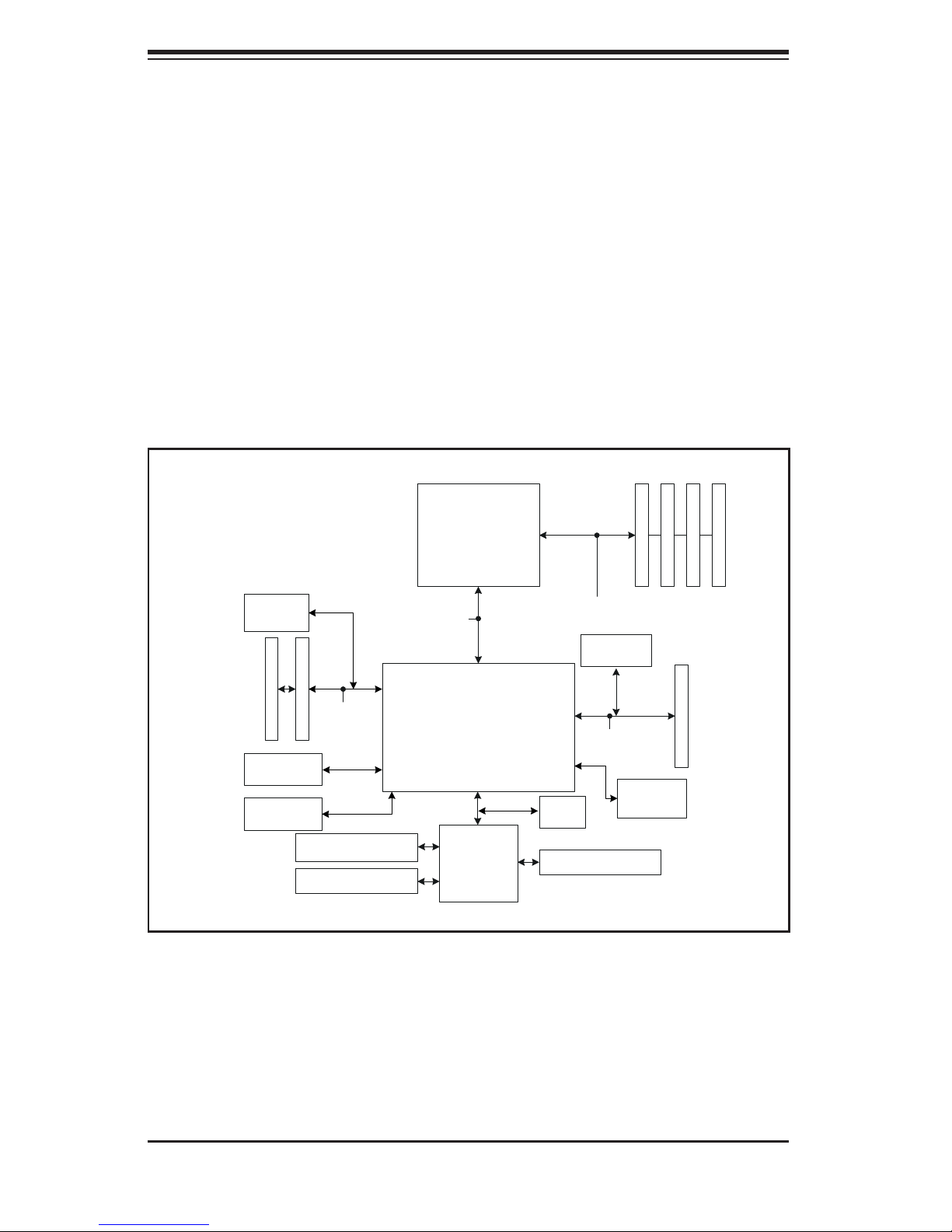
Figure 1-1 . ServerWorks HT-1000 Chipset:
System Block Diagram
Note: This is a general block diagram. Please see Chapter 5 for details.
184-pin DIMMs
33 MHz PC I Slots (2)
Rage XL
USB 2.0
UDMA100
8x H T @ 1 .6 GB/ sec
33 MHz Bus
Floppy Disk Drive
Serial Ports
AMD
Opter on
TM
Processor
ServerWorks
HT-1000
LPC Link
NS87427
Super I/O
144 - bit , 200 -400 MT/s
GLAN (2 )
133 MHz Bus
SATA
BIOS
PS/2 Kybd/Mouse
Ports ( 4)
PCI -X 133 M Hz Slot
1-4

Chapter 1: Introduction
1-3 Server Chassis Features
The 1010S-MR is a mini 1U rackmount server platform confi guration. The following
is a general outline of the main features of the SC512C-260 chassis.
System Power
When confi gured as a 1010S-MR, the SC512C-260 chassis includes a single 260W
power supply.
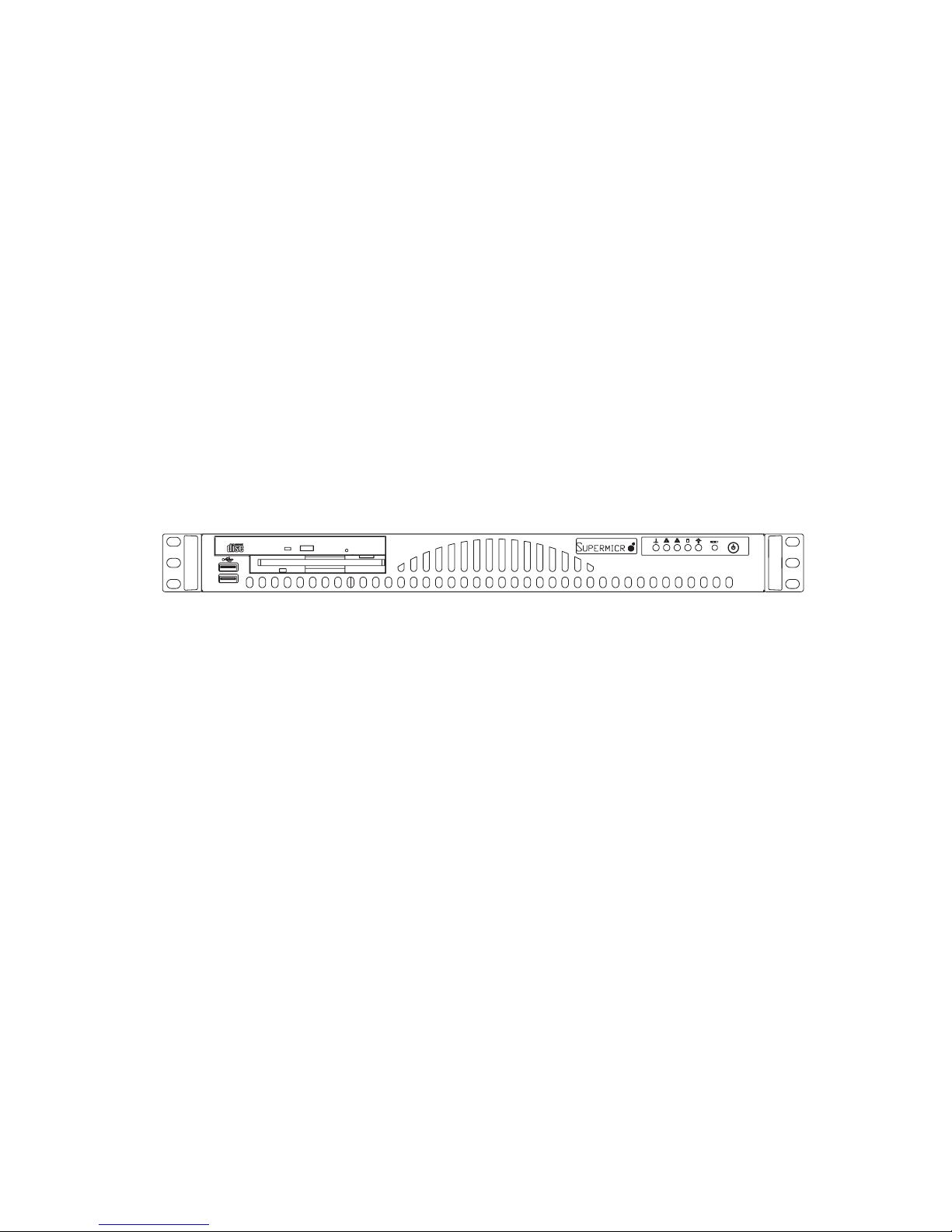
Control Panel
The SC512C-260's control panel provides important system monitoring and con-
trol information. LEDs indicate power on, network activity, hard disk drive activity,
overheat warning and fan failure. The control panel also includes a main power
button and a system reset button.
Rear I/O Panel
The rear I/O panel on the SC512C-260 provides one motherboard expansion slot,
one COM port (another is internal), two USB ports, PS/2 mouse and keyboard ports,
a graphics port and two Gb Ethernet ports. (See Figure 1-2.)
Cooling System
The SC512C-260 chassis has an innovative cooling design that features a 10-cm
blower system cooling fan. The blower fan plugs into a chassis fan header on the
motherboard and operates at full rpm continuously.
1-5

AS1010S-MR User's Manual
Notes
1-6

Chapter 2: Server Installation
Chapter 2
Server Installation
2-1 Overview
This chapter provides a quick setup checklist to get your 1010S-MR up and run-
ning. Following the steps in the order given should enable you to have the system
operational within a minimal amount of time. This quick setup assumes that your
1010S-MR system has come to you with the processor and memory preinstalled.
If your system is not already fully integrated with a motherboard, processor, system
memory etc., please turn to the chapter or section noted in each step for details on
installing specifi c components.
2-2 Unpacking the System
You should inspect the box the 1010S-MR was shipped in and note if it was dam-
aged in any way. If the server itself shows damage, you should fi le a damage claim
with the carrier who delivered it.
Decide on a suitable location for the rack unit that will hold the 1010S-MR. It should
be situated in a clean, dust-free area that is well ventilated. Avoid areas where
heat, electrical noise and electromagnetic fi elds are generated. You will also need
it placed near a grounded power outlet. Read the Rack and Server Precautions in
the next section.
2-3 Preparing for Setup
The 1010S-MR does not ship with a rack rail hardware package as the system can
be rack mounted without the use of rails. An optional rack rail package is avail-
able if you wish to order from Supermicro. Follow the steps in the order given to
complete the installation process in a minimal amount of time. Please read this
section in its entirety before you begin the installation procedure outlined in the
sections that follow.
2-1
AS1010S-MR User's Manual
Choosing a Setup Location
- Leave enough clearance in front of the rack to enable you to open the front
door completely (~25 inches).
- Leave approximately 30 inches of clearance in the back of the rack to allow
for suffi cient airfl ow and ease in servicing.
- This product is for installation only in a Restricted Access Location (dedicated
equipment rooms, service closets and the like).
!
Warnings and Precautions!
!
Rack Precautions
- Ensure that the leveling jacks on the bottom of the rack are fully extended to
the fl oor with the full weight of the rack resting on them.
- In a single rack installation, stabilizers should be attached to the rack.
- In multiple rack installations, the racks should be coupled together.
- Always make sure the rack is stable before extending a component from the
rack.
- You should extend only one component at a time - extending two or more
simultaneously may cause the rack to become unstable.
Server Precautions
- Review the electrical and general safety precautions in Chapter 4.
- Determine the placement of each component in the rack before you install the
rails.
- Install the heaviest server components on the bottom of the rack fi rst, and then
work up.
- Use a regulating uninterruptible power supply (UPS) to protect the server from
power surges, voltage spikes and to keep your system operating in case of a
power failure.
-
Allow the power supply units and hot plug Serial ATA drive to cool before
touching them.
-
Always keep the rack's front door and all panels and components on the serv-
ers closed when not servicing to maintain proper cooling.
2-2

Chapter 2: Server Installation
Rack Mounting Considerations
Ambient Operating Temperature
If installed in a closed or multi-unit rack assembly, the ambient operating tempera-
ture of the rack environment may be greater than the ambient temperature of the
room. Therefore, consideration should be given to installing the equipment in an
environment compatible with the manufacturer’s maximum rated ambient tempera-
ture (Tmra).
Reduced Airfl ow
Equipment should be mounted into a rack so that the amount of airfl ow required
for safe operation is not compromised.
Mechanical Loading
Equipment should be mounted into a rack so that a hazardous condition does not
arise due to uneven mechanical loading.
Circuit Overloading
Consideration should be given to the connection of the equipment to the power
supply circuitry and the effect that any possible overloading of circuits might have
on overcurrent protection and power supply wiring. Appropriate consideration of
equipment nameplate ratings should be used when addressing this concern.
Reliable Ground
A reliable ground must be maintained at all times. To ensure this, the rack itself
should be grounded. Particular attention should be given to power supply connec-
tions other than the direct connections to the branch circuit (i.e. the use of power
strips, etc.).
2-3
AS1010S-MR User's Manual
2-4 Installing the System into a Rack
(Rack hardware optional)
This section provides information on installing the 1010S-MR into a rack unit. If
the system has already been mounted into a rack, you can skip ahead to Sections
2-5 and 2-6.
Basic Installation Procedure
The 1010S-MR server comes with two rack mounting brackets, which are located on
each side at the front of the chassis. To mount the system into a rack, simply screw
these brackets directly to the front of the rack (two screws for each bracket).
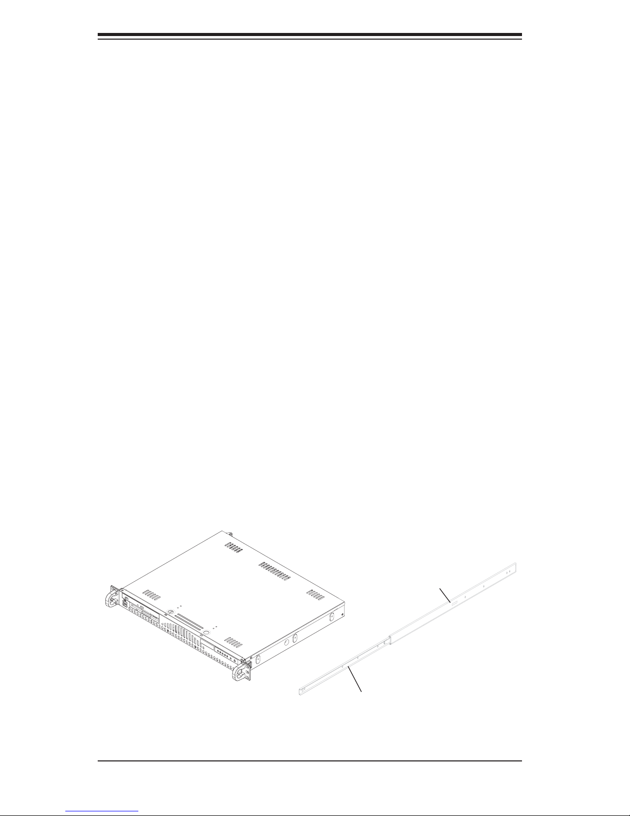
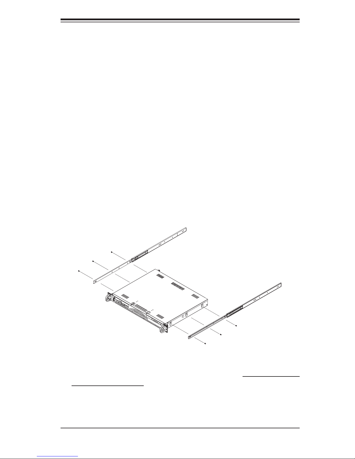
Installing with Rackmount Kit
This section is only for customers that have the optional rack mount kit (CSE-PT8).
Each of these assemblies consist of two sections: an inner rail that secures to the
chassis and an outer rail that secures directly to the rack itself (see Figure 2-1).
This is a guideline for installing the unit into a rack with the optional rack kit. You
should also refer to the installation instructions that came with the rack unit you are
using. Be aware that there are a variety of rack units on the market, which may
mean the assembly procedure will differ slightly.
Figure 2-1. Identifying the Sections of the Rack Rails
B
A
2-4
Chapter 2: Server Installation
Installing the Chassis Rails
The two rail sections must be detached from each other prior to installation. Do this
by depressing the locking tab on the inner rail to release it from its locked position
then pull the two rails completely apart. Do this for both the left and right side rack
rail assemblies.
Position the fixed chassis rail sections you just removed along the side of
the chassis making sure the three screw holes line up.
are left/right specifi c. Screw the rail securely to the side of the chassis (see Figure
2-2). Repeat this procedure for the other rail on the other side of the chassis. You
will also need to attach the rail brackets when installing into a telco rack.
Locking Tabs: Both chassis rails have a locking tab, which serves two functions.
The fi rst is to lock the server into place when installed and pushed fully into the
rack, which is its normal position. Secondly, these tabs also lock the server in place
when fully extended from the rack. This prevents the server from coming completely
out of the rack when you pull it out for servicing.
Note that these two rails
Figure 2-2. Installing Chassis Rails
Installing the Rack Rails
Determine where you want to place the 1010S-MR in the rack (see Rack and Server
Precautions in Section 2-3). Position the fi xed rack rail/sliding rail guide assemblies
at the desired location in the rack, keeping the sliding rail guide facing the inside
of the rack. Screw the assembly securely to the rack using the brackets provided.
Attach the other assembly to the other side of the rack, making sure that both are
at the exact same height and with the rail guides facing inward.
2-5
AS1010S-MR User's Manual
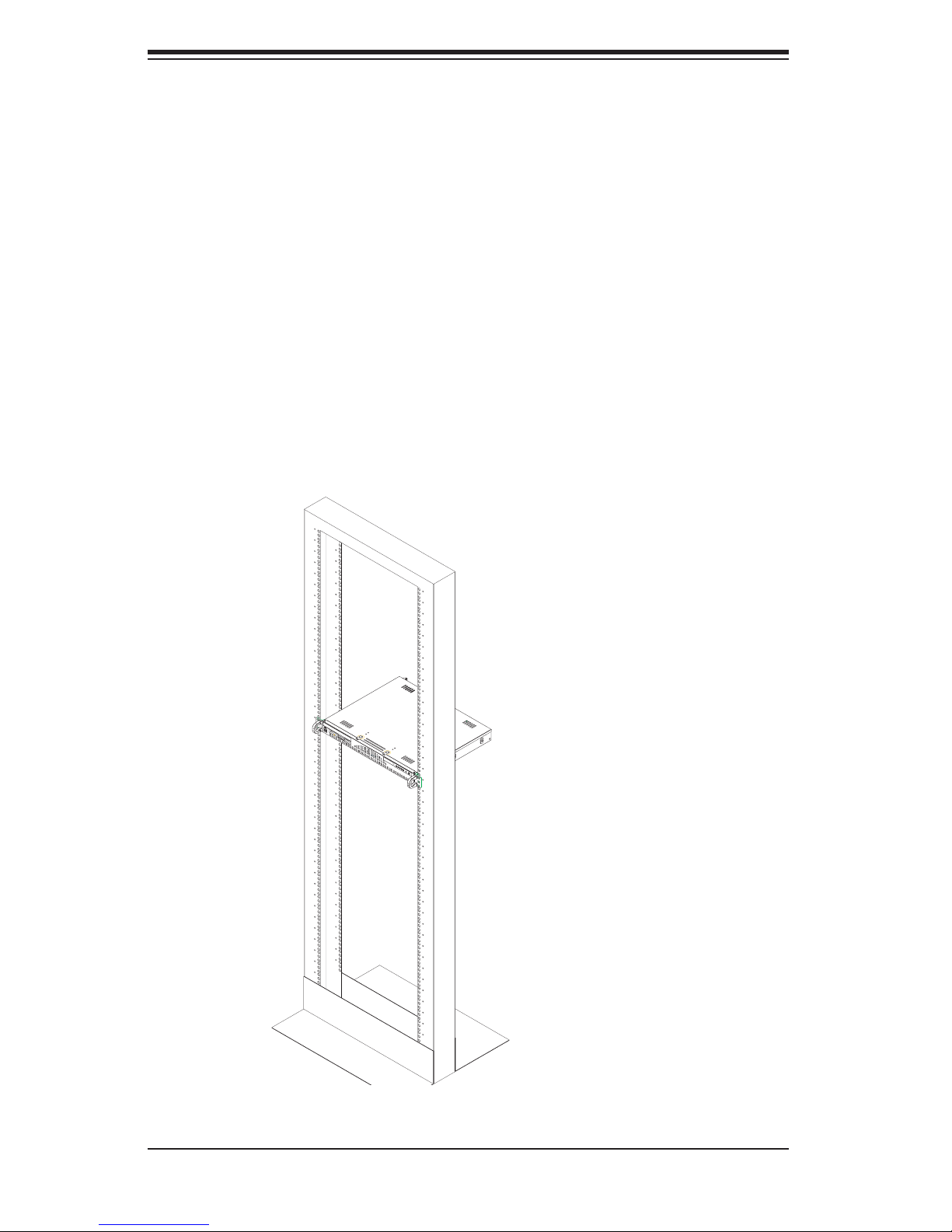
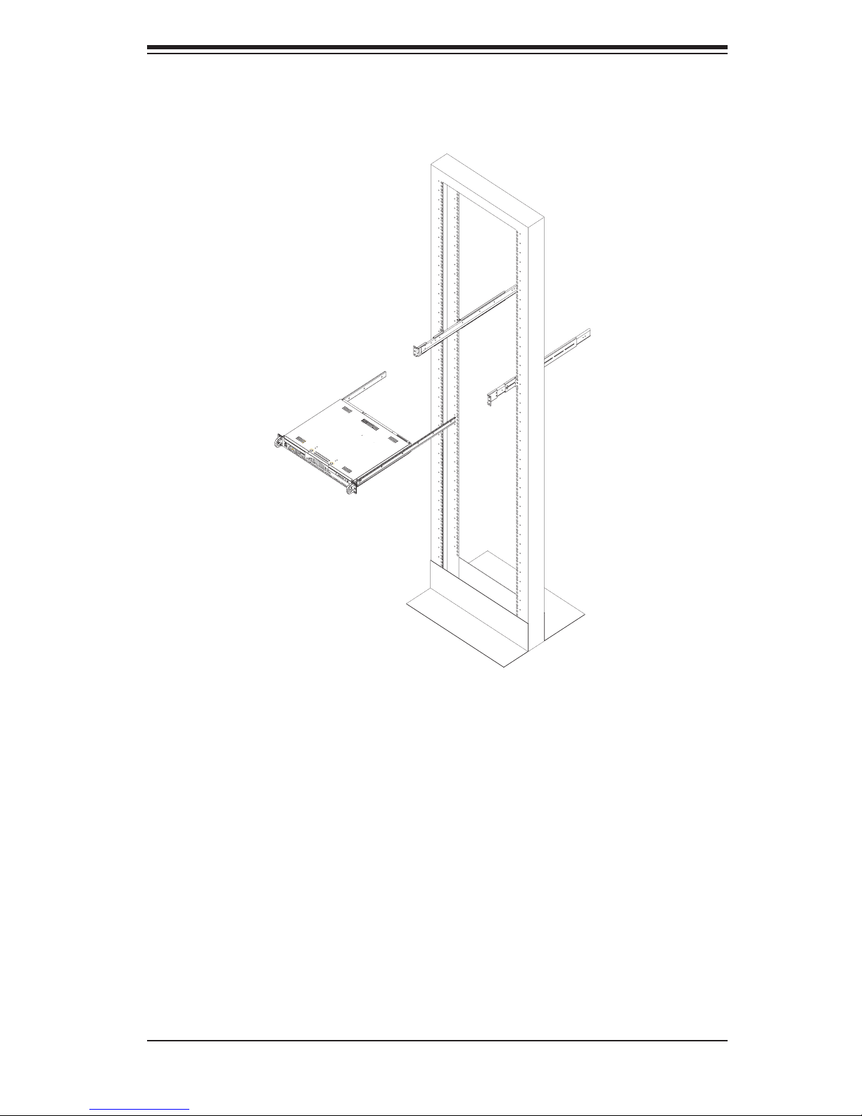
Installing the Server into the Rack
You should now have rails attached to both the chassis and the rack unit. The next
step is to install the server into the rack. Do this by lining up the rear of the chas-
sis rails with the front of the rack rails. Slide the chassis rails into the rack rails,
keeping the pressure even on both sides (you may have to depress the locking
tabs when inserting). See Figure 2-3.
When the server has been pushed completely into the rack, you should hear the
locking tabs "click". Finish by inserting and tightening the thumbscrews that hold
the front of the server to the rack.
Figure 2-3. Installing the Server into a Rack: Basic
2-6
Chapter 2: Server Installation
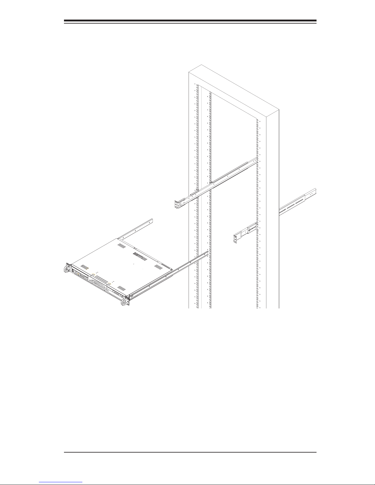
Figure 2-4. Installing the Server into a Rack: w/ Rackmount Kit
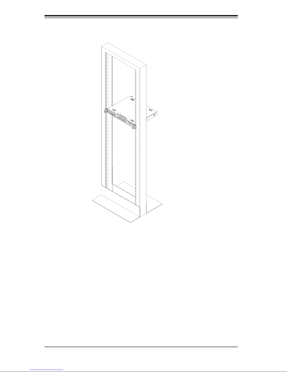
Installing the Server into a Telco Rack
If you are installing the 1010S-MR into a Telco type rack, follow the directions given
on the previous pages for rack installation. The only difference in the installation
procedure will be the positioning of the rack brackets to the rack. They should be
spaced apart just enough to accomodate the width of the telco rack.
2-7
AS1010S-MR User's Manual
Figure 2-5. Installing the Server into a Telco Rack: Basic
2-5 Checking the Motherboard Setup
After you install the 1010S-MR in the rack, you will need to open the unit to make
sure the motherboard is properly installed and all the connections have been
made.
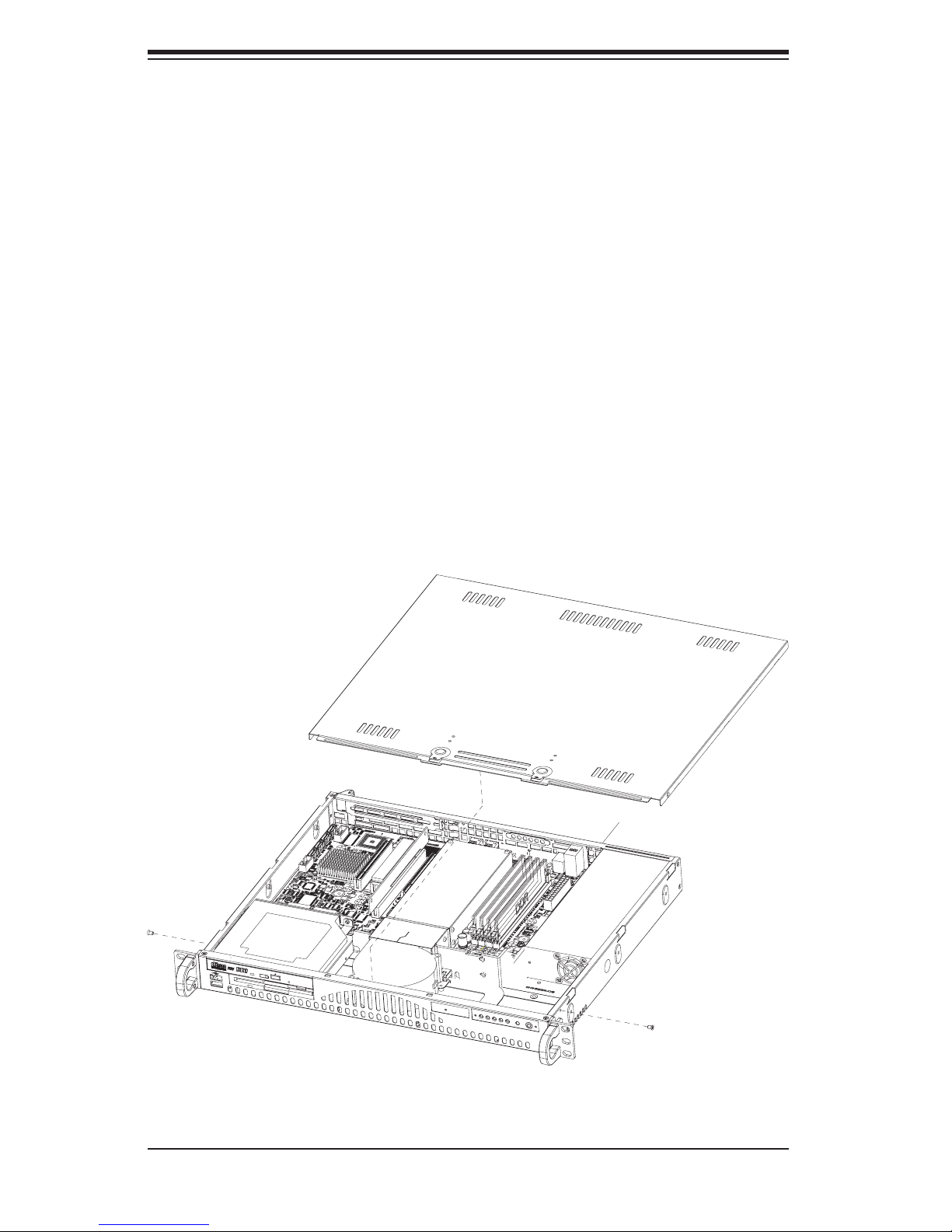
1. Accessing the inside of the system (Figure 2-7)
First, grasp the two handles on either side and pull the unit straight out until it
locks (you will hear a "click"). Then remove the screws from the lips on either
side of the chassis top cover (see Figure 2-5 for location). Next, depress the
two buttons on the top of the chassis to release the top cover while pushing
2-8
Chapter 2: Server Installation
Figure 2-6. Installing the Server into a Telco Rack: w/ Rackmount Kit
the cover away from you until it stops. You can then lift the top cover from the
chassis to gain full access to the inside of the server.
2. Check the CPU (processor)
You may have one processor already installed into the system board. The pro-
cessor should have its own heatsink attached. See Chapter 5 for instructions
on processor installation.
3. Check the system memory
Your server system may have come with system memory already installed. Make
sure all DIMMs are fully seated in their slots. For details on adding system
memory, refer to Chapter 5.
2-9
AS1010S-MR User's Manual
4. Installing add-on cards
If desired, you can install an add-on card to the system. See Chapter 5 for
details on installing a PCI add-on card.
5. Check all cable connections and airfl ow
Make sure all power and data cables are properly connected and not blocking
the airfl ow. See Chapter 5 for details on cable connections. Also, check the air
seals for damage. The air seals are located under the blower fan and beneath
the frame cross section that separates the drive bay area from the motherboard
area of the chassis.
Note: Make sure that the air seals are properly installed.
Figure 2-7. Accessing the Inside of the 1010S-MR
2-10

Chapter 2: Server Installation
2-6 Checking the Drive Bay Setup
Next, you should check to make sure the peripheral drives and the Serial ATA drive
have been properly installed and all essential connections have been made.
1. Accessing the drive bays
For servicing the Serial ATA, CD-ROM and fl oppy drives, you will need to remove
the top chassis cover. The Serial ATA disk drive is located at the front right side of
the chassis.
2. Installing a CD-ROM and fl oppy disk drives
Refer to Chapter 6 if you need to reinstall a CD-ROM and/or fl oppy disk drive to
the system.
3. Check the Serial ATA disk drives
Depending upon your system's confi guration, your system may have a Serial ATA
hard drive already installed. If you need to install a Serial ATA hard drive, please
refer to the appropriate section in Chapter 6.
4. Check the airfl ow
Airfl ow is provided by one 10-cm blower fan. The system component layout was
carefully designed to promote suffi cient airfl ow through the small 1U rackmount
space. Also note that all power and data cables have been routed in such a way
that they do not block the airfl ow generated by the fan.
5. Supplying power to the system
The last thing you must do is to provide input power to the system. Plug the power
cord from the power supply unit into a high-quality power strip that offers protec-
tion from electrical noise and power surges. It is recommended that you use an
uninterruptible power supply (UPS).
2-11

AS1010S-MR User's Manual
Notes
2-12
Chapter 3: System Interface
Chapter 3
System Interface
3-1 Overview
There are several LEDs on the control panel to keep you constantly informed of
the overall status of the system as well as the activity and health of specifi c com-
ponents. There are also two buttons on the chassis control panel. This chapter
explains the meanings of all LED indicators and the appropriate response you may
need to take.
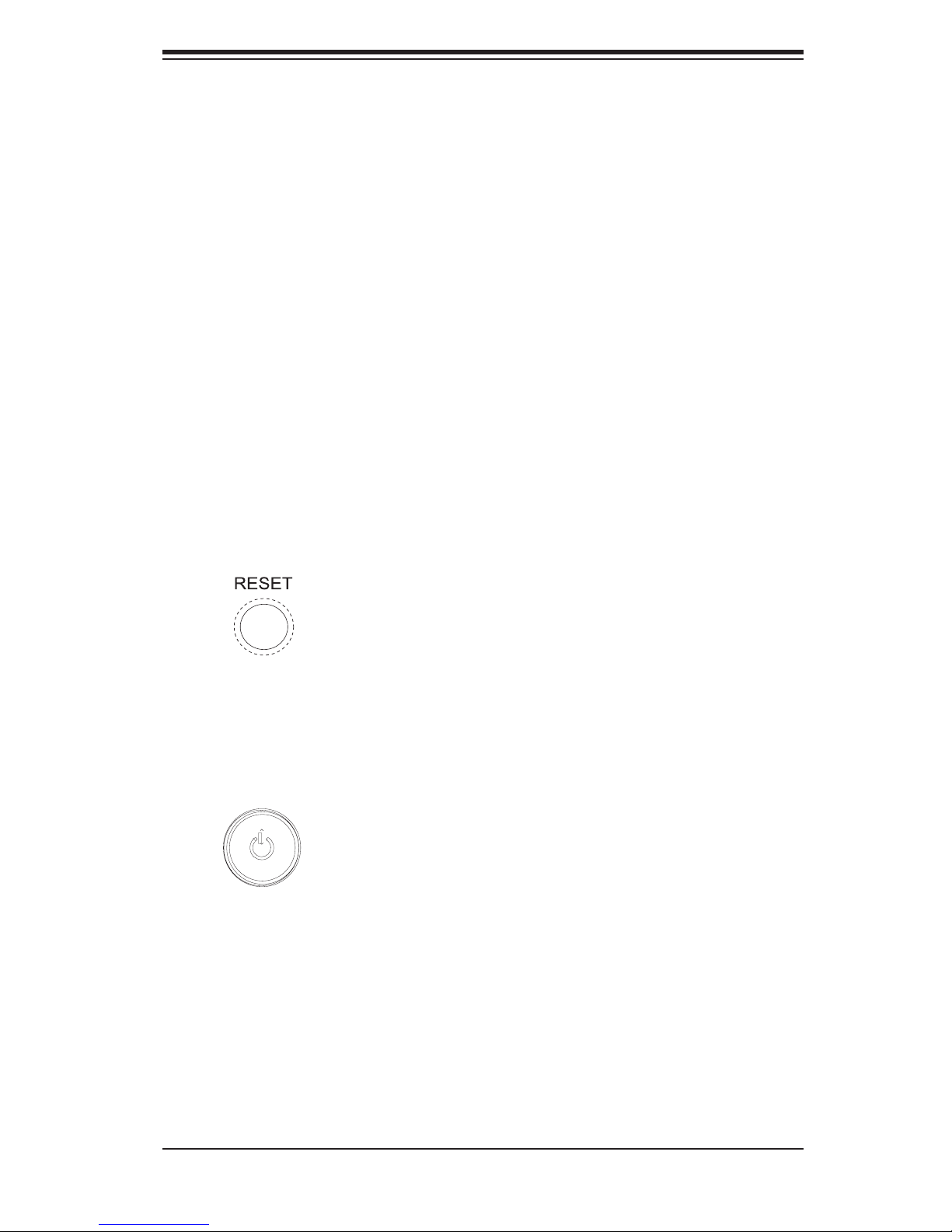
3-2 Control Panel Buttons
There are two push-button buttons located on the front of the chassis. These are
(in order from left to right) a reset button and a power on/off button.
Reset:
Power: This is the main power switch, which is used to apply or turn off the
main system power. Turning off system power with this button removes the main
power but keeps standby power supplied to the system.
The reset switch reboots the system.
3-1
 Loading...