

Page 1
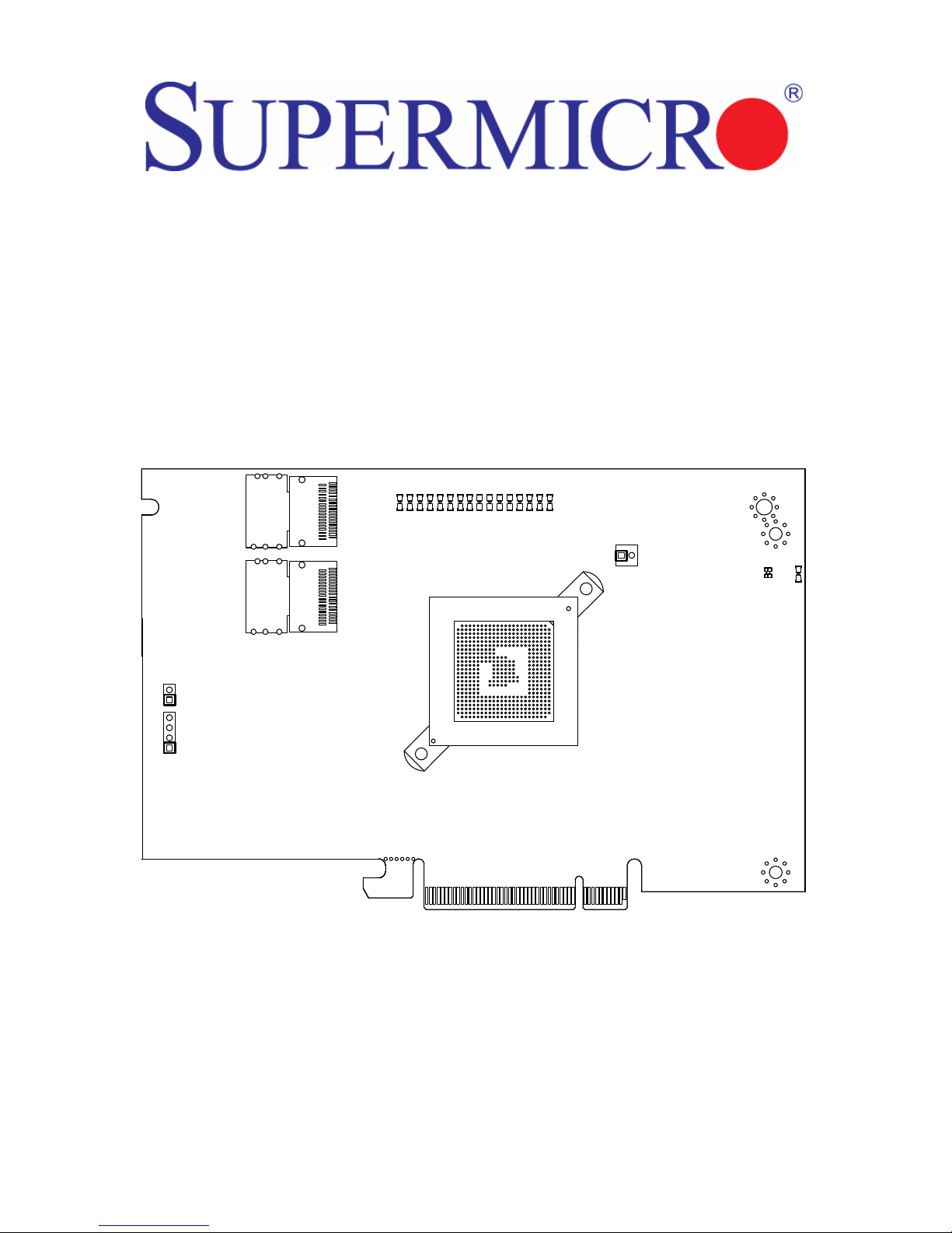
AOC-USAS2-L8i/L8e/L8iMR
Add-on Cards
User’s Manual
Revison 1.0a
Page 2
AOC-USAS2-L8i/L8e/L8iMR Add-on Card User’s Manual
The information in this User’s Manual has been carefully reviewed and i s believed to be accurate. The
vendor assumes no responsibility for any inaccuracies that may be contained in this document, makes no
commitment to update or to keep current the information in this manual, or to not ify any person or
organization of the u pdates. Plea se Note: For the most up-to-date version of this manual, please see
our web site at www.supermicro.com.
Super Micro Computer, Inc. (“Supermicro”) reserves the right to make changes to the product described
in this manual at any time and without notice. This product, including software, if any, and documentation
may not, in whole or in part, be copied, photocop ied, re produced, translated or redu ced t o any medi um or
machine without prior written consent.
IN NO EVENT WILL SUPERMICRO BE LIABLE FOR DIRECT, INDIRECT, SPECIAL, INCIDENTAL,
SPECULATIVE OR CONSEQUENTIAL DAMAGES ARISING FROM THE USE OR INABILITY TO USE
THIS PRODUCT OR DOCUMENTATION, EVEN IF ADVISED OF THE POSSIBILITY OF SUCH
DAMAGES. IN PARTICULAR, SUPERMICRO SHALL NOT HAVE LIABILITY FOR ANY HARDWARE,
SOFTWARE, OR DATA STORED OR USED WITH THE PRODUCT, INCLUDING THE COSTS OF
REPAIRING, REPLACING, INTEGRATING, INSTALLING OR RECOVERING SUCH HARDWARE,
SOFTWARE, OR DATA.
Any disputes arising between manufacturer and cu stomer shall be governed by the laws of Santa Clara
County in the State of California, USA. The State of California, Co unty of Santa Clara shall be the
exclusive venue for the resolution of any such disputes. Super Micro's total liabilit y for all claims will not
exceed the price paid for the hardware product.
FCC State ment: This equipment has been tested and found to comply with the limits for a Class A digital
device pursuant to Part 15 of the FCC Rules. These limits are designed to provide reasonable protection
against harmful interference when the equipment is operated in a commercial environment. This
equipment generates, uses, and can radiate radio frequency energy and, if not installed and used in
accordance with the manufacturer’s instruction manual, may cause harmful interference with radio
communications. Operation of this equipment in a residential area is likely to cause harmful interference,
in which case you will be required to correct the interference at your own expense.
California Best Management Practices Regulations for Perchlorate Materials: This Perchlorate warning
applies only to products containing CR (Manganese Dioxide) Lithium coin cells. Perchlorate
Material-special handling may apply. See www.dtsc.ca.gov/hazardouswaste/perchlorate for further
details.
WARNING: HANDLING OF LEAD SOLDER MATERIALS USED IN THIS
PRODUCT MAY EXPOSE YOU TO LEAD, A CHEMICAL KNOWN TO THE
STATE OF CALIFORNIA TO CAUSE BIRTH DEFECTS AND OTHER
REPRODUCTIVE HARM.
Manual Revison 1.0a
Release Date: September 22, 2010
Unless you request and receive written permission from Super Micro Computer, Inc., you may not copy
any part of this document. Information in this document is subject to change without notice.
LSI, Integrated Mirroring, Integrated RAID, Integrated Striping, Fusion-MPT, and MegaRAID are
trademarks or registered trademarks of LSI Corporation. Other produ cts and comp anies referred to herein
are trademarks or registered trademarks of their respective companies or mark holders.
Portions of this document © 2006-2007 LSI Corporation
Copyright © 2010 by Super Micro Computer, Inc.
All rights reserv ed .
Printed in the United States of America
ii
Page 3

Preface
About this Manual
This manual is written for system integrators, PC technicians and knowledgeable PC
users who intend to integrate SuperMicro's AOC-USAS2-L8i/L8e/L8IR add-on card to
their system.
Product Features
The AOC-USAS2-L8i add-on card offers the following features:
• UIO Form Factor
• Dual Internal "ipass" cable ports
• Multiple LED Activity/Failure indicators
• Supports LSI SAS 2008 standard with LSISAS 2008 SAS controller
• Supports RAID 0, 1, 1E and 10
• Supports MegaRAID Storage Manager software
• Supports 3.0 and 6.0 Gb/s SAS and SATA data transfer rates
• 8-port (internal), 6Gb/s per port
• Supports 63 devices
• Double the performance compare with SWR5
• Automatically negotiates PCI-E (1.x and 2.x) link widths
• Power management support
• Port independent auto-negotiation
• Supports SSP, SMP, STP and SATA protocols
• Zoning capability w/ SAS2 expanders
• Processor at 525 MHZ
• Dimensions: 4.376" x 6.6 " (H x L)
The AOC-USAS2-L8e add-on card offers the following features:
• UIO Form Factor
• Dual Internal "ipass" cable ports
• Multiple LED Activity/Failure indicators
• Supports LSI SAS 2008 standard with LSISAS 2008 SAS controller
• HBA – No RAID
• Supports MegaRAID Storage Manager software
• Supports 3.0 and 6.0 Gb/s SAS and SATA data transfer rates
• 8-port (internal), 6Gb/s per port
• Supports 122 devices - HBA only
• Double the performance compare with SWR5
• Automatically negotiates PCI-E (1.x and 2.x) link widths
i
Page 4

AOC-USAS2-L8i/L8e/L8iMR Add-on Card User’s Manual
• Power management support
• Port independent auto-negotiation
• Supports SSP, SMP, STP and SATA protocols
• Zoning capability w/ SAS2 expanders
• Processor at 525 MHZ
• Dimensions: 4.376" x 6.6 " (H x L)
The AOC-USAS2-L8IR add-on card offers the following features:
• UIO Form Factor
• Dual Internal "ipass" cable ports
• Multiple LED Activity/Failure indicators
• Supports LSI SAS 2008 standard with LSISAS 2008 SAS controller
• Supports MegaRAID Storage Manager software
• 8-port (internal), 6Gb/s per port
• Supports 16 devices
• Double the performance compare with SWR5
• Automatically negotiates PCI-E (1.x and 2.x) link widths
• Power management support
• Supports 3.0 and 6.0 Gb/s SAS and SATA data transfer rates
• Port independent auto-negotiation
• Supports SSP, SMP, STP and SATA protocols
• Zoning capability w/ SAS2 expanders
• OS Support :
• Processor at 525 MHZ
• Supports RAID 0,1,10 and 5 (with AOC-SAS2-RAID5-KEY add-on card)
• Dimensions: 4.376" x 6.6 " (H x L)
Operating Systems Supported
Both add-on cards support the following Operating Systems (OS):
• Windows XP/Windows 2003/Windows 2008/Vista
• Red Hat Enterprise Linux/SUSE Linux
An Important Note to Users
All images and layouts shown in this user's guide are based upon the latest PCB
Revision available at the time of publishing. The card you have received may or may not
look exactly the same as the graphics shown in this manual.
ii
Page 5

Contacting SuperMicro
Headquarters
Address: Super Micro Computer , Inc.
980 Rock Ave.
San Jose, CA 95131 U.S.A.
Tel: +1 (408) 503-8000
Fax: +1 (408) 503-8008
Email: [email protected] (General Information)
[email protected] (Technical Support)
Web Site: www.supermicro.com
Europe
Preface
Address: Super Micro Computer B.V.
Het Sterrenbeeld 28, 5215 ML
‘s-Hertogenbosch, The Netherlands
Tel: +31 (0) 73-6400390
Fax: +31 (0) 73-6416525
Email: [email protected] (General Information)
[email protected] (Technical Support)
[email protected] (Customer Support)
9
Asia-Pacific
Address: Super Micro Computer , Inc.
4F, No. 232-1, Liancheng Rd.
Chung-Ho 235, Taipei County
Taiwan, R.O.C.
Tel: +886-(2) 8226-3990
Fax: +886-(2) 8226-3991
Web Site: www.supermicro.com.tw
Technical Support:
Email: [email protected]
Tel: +886-2-8228-1366, ext. 132 or 139
iii
Page 6

AOC-USAS2-L8i/L8e/L8iMR Add-on Card User’s Manual
Notes
iv
Page 7

Table of Contents
Chapter 1 Safety Guidelines..........................................................1-1
1-1 ESD Safety Guidelines.....................................................................1-1
1-2 General Safety Guidelines...............................................................1-1
1-3 An Important Note to Users.............................................................1-1
Chapter 2 Connectors, Jumpers and Indicators...............2-1
2-1 Front Connectors and Pin Definitions............................................2-1
Internal SAS Connectors ........................................................................2-2
Active LED Connector.................................. ...........................................2-2
AOC-SAS2-RAID5-KEY Connector........................................................2-2
2-2 LED Indicators ...................................................................................2-3
2-3 RAID Minimum Drive Requirements..............................................2-4
Chapter 3 RAID Modes, Firmware and Drivers...................3-1
3-1 RAID Modes.......................................................................................3-1
3-2 Getting Firmware Downloads..........................................................3-1
LSI MegaRAID iMR/IR Firmware Flash Process............................. .......3-2
3-3 Downloading RAID Mode Drivers...................................................3-2
3-4 Activating RAID Modes in OPROM BIOS.....................................3-3
Chapter 4 Integrated Mirroring and Integrated Mirroring
Enhanced...................................................................................................4-1
4-1 Introduction.........................................................................................4-1
4-2 IM and IME Features........................................................................4-2
4-3 IM/IME Description............................................................................4-2
4-4 Mirrored Volume Features...............................................................4-4
Resynchronization with Concurrent Host I/O Operation.........................4-5
Hot Swapping..........................................................................................4-5
Hot Spare Disk........................................................................................4-5
Online Capacity Expansion................. ... ... ..............................................4-5
Media Verification.............................................. ... ...................................4-6
Disk Write Caching .................................................................................4-6
NVSRAM Usage................................................................................. ....4-6
Background Initialization.........................................................................4-6
Consistency Check................................ .......................................... ... ....4-6
Make Data Consistent.............................................................................4-6
v
Page 8

AOC-USAS2-L8i/L8e/L8iMR Add-on Card User’s Manual
4-5 Creating Mirrored Volumes..............................................................4-7
Starting the LSI SAS2 BIOS Configuration Utility ...................................4-7
Creating an Integrated Mirroring Volume................................................4-8
Creating an Integrated Mirroring Enhanced or Integrated Mirro ri ng and
Striping Volume.......................................................................................4-9
Expanding an Integrated Mirroring Volume with OCE ..........................4-10
4-6 Hot Spare Disks...............................................................................4-11
Creating Hot Sp are Disks.................. .......................................... .. ........4-11
Deleting Hot Spare Disks......................................................................4-12
4-7 Other Configuration Tasks.............................................................4-12
Viewing Volume Properties.......................... ... ......................................4-12
Running a Consistency Check..............................................................4-13
Activating an Array................................................................................4-13
Deleting an Array..................................................................................4-14
Locating Disk Drives in a Volume .........................................................4-14
Selecting a Boot Disk..................... ... .. .......................................... ... .....4-15
Chapter 5 Integrated Striping........................................................5-1
5-1 Introduction.........................................................................................5-1
5-2 IS Features.........................................................................................5-2
5-3 IS Description.....................................................................................5-2
5-4 Integrated Striping Firmware...........................................................5-3
Metadata Support....................................................................................5-3
SMART Support......................................................................................5-4
Disk Write Caching .................................................................................5-4
5-5 Fusion-MPT Support.........................................................................5-4
5-6 IS Configuration Overview...............................................................5-4
5-7 Creating IS Volumes.........................................................................5-4
5-8 Other Configuration Tasks...............................................................5-6
Viewing IS Volume Properties.................................................................5-6
Activating an Array..................................................................................5-6
Deleting an Array....................................................................................5-7
Locating a Disk in a Volume....................................................................5-7
Selecting a Boot Disk..............................................................................5-8
Chapter 6 Using the Configuration Utility.............................6-1
6-1 Hardware and Software Requirements..........................................6-1
6-2 Commands and Interface Description ...........................................6-2
Common Command-Line Parameters....................................................6-3
vi
Page 9

Table of Contents
CREATE Command................................................................................6-3
Command Line.............. ... .......................................... .. ........................6-4
Parameters...........................................................................................6-4
Program Return Value..........................................................................6-4
DELETE Command .......................... .. .......................................... ... .......6-4
Command Line.............. ... .......................................... .. ........................6-4
Parameters...........................................................................................6-5
Program Return Value..........................................................................6-5
DISPLAY Command ...............................................................................6-5
Command Line.............. .......................................... ... .. ........................6-5
Parameters...........................................................................................6-5
Program Return Value..........................................................................6-5
Sample Output............................... .. .......................................... ... ... ....6-6
Values ..................................................................................................6-7
HOTSPARE Command................................................ ........................6-8
Command Line.............. .......................................... ... .. ........................6-9
Parameters...........................................................................................6-9
Program Return Value..........................................................................6-9
STATUS Command........................ .......................................... ...............6-9
Command Line.............. .......................................... ... .. ........................6-9
Parameters...........................................................................................6-9
Program Return Value..........................................................................6-9
Sample Output............................... .. .......................................... ........6-10
Values ................................................................................................6-10
LIST Command.....................................................................................6-10
Command Line.............. .......................................... ... ........................6-10
Parameters.........................................................................................6-11
Program Return Value........................................................................6-11
Sample Output............................... .. .......................................... ........6-11
MFGPAGE Command............................................. ..............................6-11
Command Line.............. .......................................... ... ........................6-11
Parameters.........................................................................................6-11
Program Return Value........................................................................6-11
CONSTCHK Command........................................................................6-12
Command Line.............. .......................................... ... ........................6-12
Parameters.........................................................................................6-12
Program Return Value........................................................................6-12
ACTIVATE Command ...........................................................................6-12
Command Line.............. .......................................... ... ........................6-12
Parameters.........................................................................................6-12
vii
Page 10

AOC-USAS2-L8i/L8e/L8iMR Add-on Card User’s Manual
Program Return Value........................................................................6-12
LOCATE Command ..............................................................................6-13
Command Line.............. .......................................... ... ........................6-13
Parameters.........................................................................................6-13
Program Return Value........................................................................6-13
LOGIR Command.................................................................................6-13
Command Line.............. .......................................... ... ........................6-13
Parameters.........................................................................................6-13
Program Return Value........................................................................6-13
Chapter 7 SAS2 BIOS Configuration Utility..........................7-1
7-1 Starting the LSI SAS2 BIOS Configuration Utility ........................7-1
7-2 Creating a RAID 1 Volume...............................................................7-3
7-3 Creating a RAID 1E or RAID 10 Volume.......................................7-8
7-4 Creating a RAID 0 Volume.............................................................7-10
7-5 Expanding an Integrated Mirroring Volume with OCE...............7-12
7-6 Hot Spare Disks...............................................................................7-15
Creating Hot Sp are Disks.................. .......................................... .. ........7-15
Deleting Hot Spare Disks......................................................................7-17
7-7 Other Configuration Tasks.............................................................7-17
Viewing Volume Properties.......................... ... ......................................7-17
Changing Properties.............................................................................7-17
Running a Consistency Check..............................................................7-20
Activating a Volume ..............................................................................7-20
Deleting an Volume...............................................................................7-21
Locating Disk Drives in a Volume .........................................................7-22
Selecting a Boot Disk..................... ... .. .......................................... ... .....7-23
Changing Boot Support.........................................................................7-23
Chapter 8 MegaRAID Overview and Installation...............8-1
8-1 Overview.............................................................................................8-1
Creating Storage Configurations.............................................................8-1
8-2 Hardware and Software Requirements..........................................8-2
8-3 Installing for Windows.......................................................................8-2
8-4 Installing for Linux.............................................................................8-3
Linux Error Messages.............................................................................8-4
Chapter 9 MegaRAID Window and Menus ............................9-1
9-1 Starting MegaRAID St orage Manager Software...........................9-1
viii
Page 11

Table of Contents
9-2 MegaRAID Storage Manager Window...........................................9-2
Physical/Logical View Panel...................................................................9-3
Properties/Operations/Graphical View Panel..........................................9-3
Event Log Panel........................................ ..............................................9-4
Menu Bar ................................................................................................9-4
File Menu .............................................................................................9-4
Operations Menu..................................................................................9-4
Group Operations Menu.......................................................................9-4
Tools Menu...........................................................................................9-4
Log Menu........................... ... .......................................... .....................9-4
Help Menu............ .......................................... ......................................9-5
9-3 Creating a New Storage Configuration..........................................9-5
Creating a Virtual Drive Using the Simple Method..................................9-7
Creating a Virtual Drive Using the Advanced Method.............................9-9
9-4 Changing Virtual Disk Properties..................................................9-12
9-5 Deleting a Virtual Disk....................................................................9-13
9-6 Controller Configuration Files........................................................9-13
Saving a Storage Configur at ion to Disk................................................9-13
Adding a Configuration .........................................................................9-14
Clearing a Configuration.......................................................................9-14
9-7 Flashing Firmware...........................................................................9-15
9-8 Configuring Alerts............................................................................9-16
ix
Page 12

AOC-USAS2-L8i/L8e/L8iMR Add-on Card User’s Manual
Notes
x
Page 13

Chapter 1
Safety Guidelines
To avoid personal injury and property damage, carefully follow all the safety steps listed
below when accessing your system or handling the components.
1-1 ESD Safety Guidelines
Electric Static Discharge (ESD) can damage electronic components. T o prevent damage
to your system, it is important to handle it very carefully. The following measures are
generally sufficient to protect your equipment from ESD.
• Use a grounded wrist strap designed to prevent static discharge.
• Touch a grounded metal object before removing a component from the antistatic
bag.
• Handle the add-on card by its edges only; do not touch its components, peripheral
chips, memory modules or gold contacts.
• When handling chips or modules, avoid touching their pins.
• Put the card and peripherals back into their antistatic bags when not in use.
1-2 General Safety Guidelines
• Always disconnect power cables before installing or removing any components from
the computer.
• Disconnect the power cable before installing or removing any cables from the
system.
• Make sure that the add-on card is securely and properly installed on the
motherboard to prevent damage to the system due to power shortage.
1-3 An Important Note to Users
All images and layouts shown in this user's guide are based upon the latest PCB
Revision available at the time of publishing. The card you have received may or may not
look exactly the same as the graphics shown in this manual.
1-1
Page 14

AOC-USAS2-L8i/L8e/L8iMR Add-on Card User’s Manual
Notes
1-2
Page 15
Chapter 2
1
1
2
3
Connectors, Jumpers and Indicators
2-1 Front Connectors and Pin Definitions
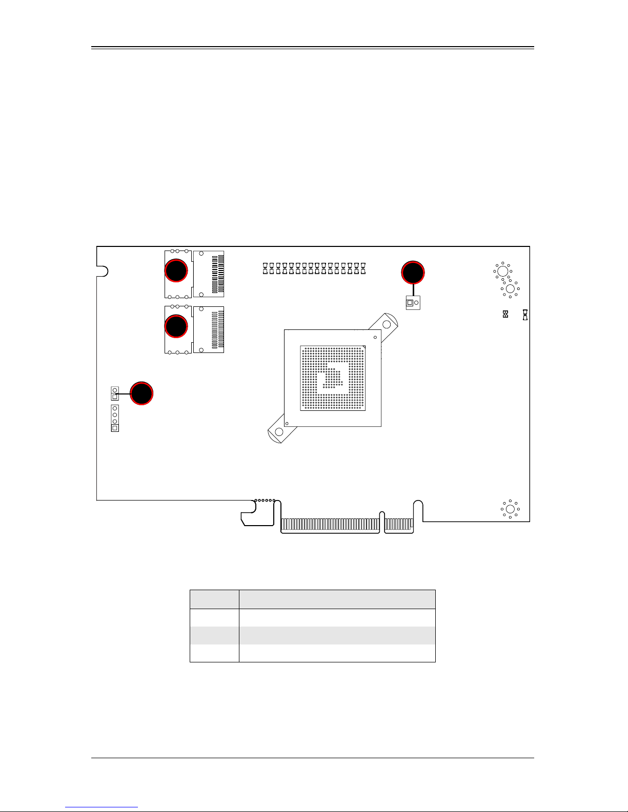
Connectors are used to attach the add-on card to the system’s mainboard and other
peripherals (see Figure 2-1).
Figure 2-1. AOC-USAS2-L8i/L8e/L8iMR Add-on Card Front Connectors and Jumpers
Table 2-1 lists the add-on card’s front connectors.
Table 2-1. Front Connectors and Pin Definitions
Number Description
1 Internal SAS Connectors
2 Front Panel LED Connector
3 AOC-SAS2-RAID5-KEY Connector
2-1
Page 16
AOC-USAS2-L8i/L8e/L8iMR Add-on Card User’s Manual
Internal SAS Connectors
The Internal SAS ports (SFF-8087 connector) connect to the backplane allowing the
motherboard to access the hard drives and RAID capabilities. Each connector supports
up to four hard drives allowing the add-on card to support a maximum of eight. (SAS 0-3
and SAS 4-7).
Use a single port SAS "ipass" cable (SuperMicro order number CBL-0108L-02).
Active LED Connector
The LED connector allows the add-on card to display activity and status using a
standard LED panel. Table 2 -2 lists the pin definitions for this connector.
Table 2-2. Front Jumpers and Pin Definitions
Number Description
1A - LED+
2 A - LED-
AOC-SAS2-RAID5-KEY Connector
This connector allows you to connect a AOC-SAS2-RAID5-KEY in order to allow RAID 5
operation on the AOC-USAS2-L8i/L8e/L8iMR add-on card. See Chapter 3 for details.
2-2
Page 17
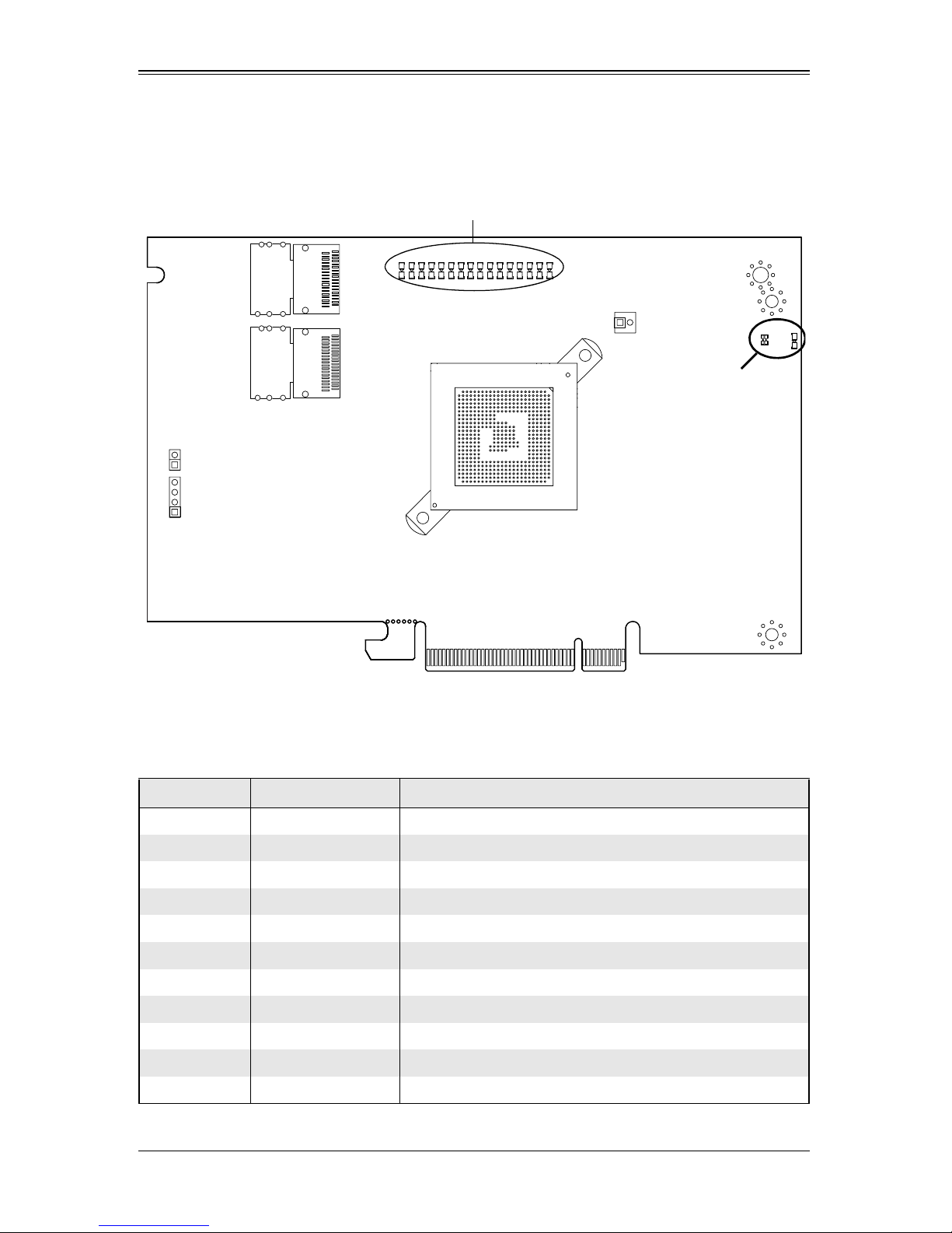
2-2 LED Indicators
LED1 and LED2
A0 - A7/PE0 - PE7
Chapter 2: Connectors, Jumpers and Indicators
Figure 2-2. LED Indicators
Figure 2-2 displays LED indicators on the add-on card, while table lists the individual
LEDs, their state and their specification.
Table 2-3. Front Pane LEDs
LED State Specification
LED1 Flashing SAS Port Activity
LED2 Flashing Heartbeat and Fault
PE0 On Fault in HDD #0
PE1 On Fault in HDD #1
PE2 On Fault in HDD #2
PE3 On Fault in HDD #3
PE4 On Fault in HDD #4
PE5 On Fault in HDD #5
PE6 On Fault in HDD #6
PE7 On Fault in HDD #7
A0 Flashing Normal Activity in HDD #0
2-3
Page 18
AOC-USAS2-L8i/L8e/L8iMR Add-on Card User’s Manual
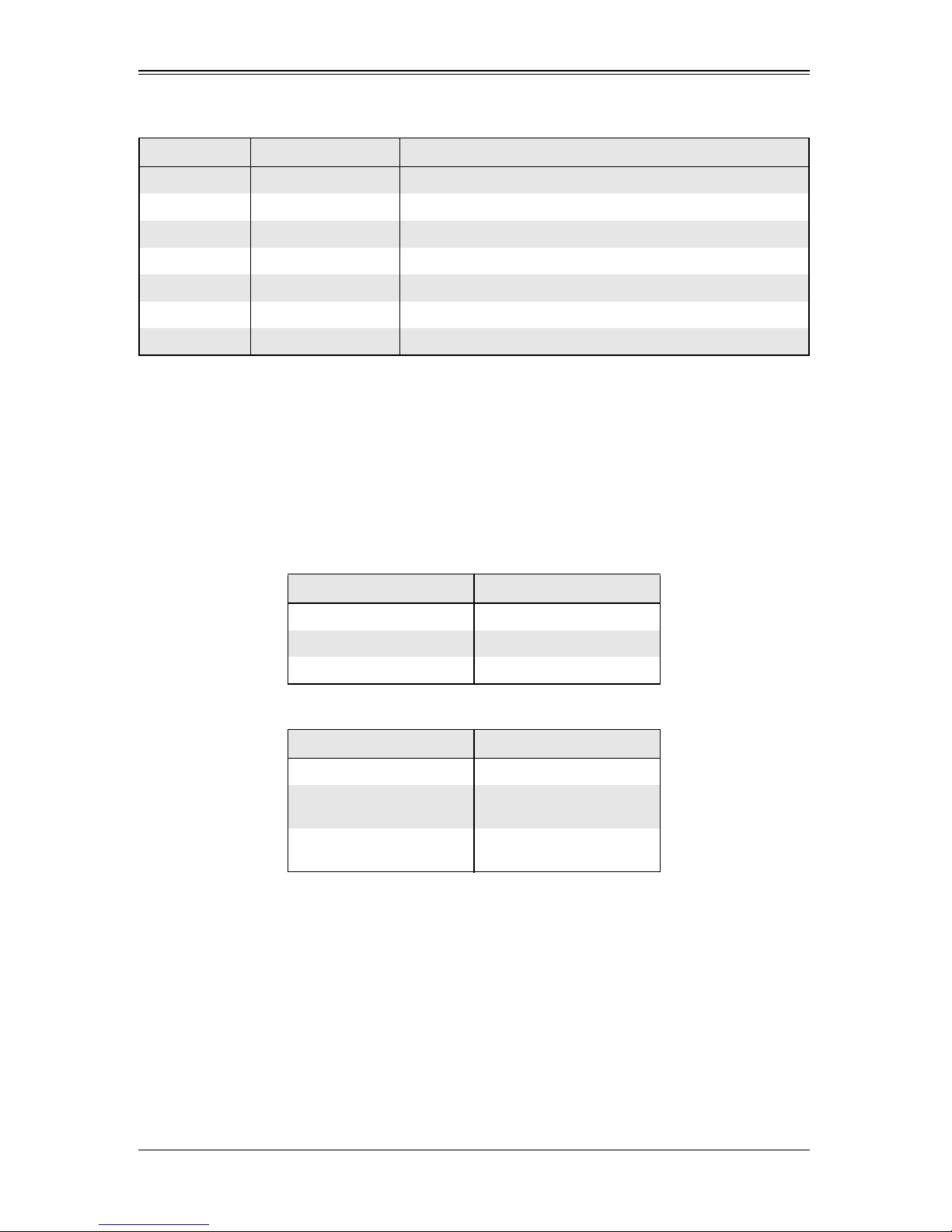
Table 2-3. Front Pane LEDs (Continued)
LED State Specification
A1 Flashing Normal Activity in HDD #1
A2 Flashing Normal Activity in HDD #2
A3 Flashing Normal Activity in HDD #3
A4 Flashing Normal Activity in HDD #4
A5 Flashing Normal Activity in HDD #5
A6 Flashing Normal Activity in HDD #6
A7 Flashing Normal Activity in HDD #7
2-3 RAID Minimum Drive Requirements
Use Table 2-4 to determine the minimum number of hard drives needed to set up a
RAID environment in SR mode for the AOC-USAS2-L8i add-on card. Use Table 2-5 to
determine the minimum number of hard drives needed to set up a RAID environment in
IR mode for the AOC-USAS2-L8iMR add-on card. The AOC-USAS2-L8e add-on card
uses HBA and not RAID, so it does not use these modes.
Table 2-4. RAID Minimum Drive Requirements for SR Mode
RAID Minimum Hard Drives
RAID 0 2
RAID 1 2
RAID 10 4 (Two RAID 1 Arrays)
Table 2-5. RAID Minimum Drive Requirements for IR Mode
RAID Minimum Hard Drives
RAID 0 (Integrated Striping) 2
RAID 1 (Integrated
Mirroring)
RAID 1E (Integrated
Mirroring Enhanced)
2
3
2-4
Page 19

Chapter 3
RAID Modes, Firmware and Drivers
To change RAID modes from the AOC-USAS2-L8i/L8e add-on card’s default IT Mode,
you need to flash your system’s BIOS with a Firmware download and install drivers for
the RAID mode to your operating system.
3-1 RAID Modes
There are two RAID modes that are supported by the AOC-USAS2-L8i/L8e add-on
card:
• IT Mode (Initiator and Target Mode): This is the default mode for the
AOC-USAS2-L8e add-on card. The maximum support for this mode is up to 122
hard disk drives under expander topology. This mode does not support RAID.
This mode requires an IT mode firmware flash to the BIOS and an IT mode driver
installation to the OS.
• IR Mode (Integrated RAID Mode): In Integrated Raid™ mode the integrated ARM
chip on the AOC-USAS2-L8i add-on card creates Integrated Mirroring™ (IM, RAID
1), Integrated Mirroring Enhanced (IME, RAID 1E) and Integrated Striping (IS, RAID
0) through the chipset’s BIOS and the system’s OS. The maximum support for this
IR mode is up to 63 hard disk drives under an expander topology.
See Chapter 4: "Integrated Mirroring and Integrated Mirroring Enhanced" on
page 4-1 and Chapter 5: "Integrated Striping" on page 5-1 for details on Integrated
Mirroring Enhanced or Integrated Striping.
This RAID mode requires an IR mode firmware flash to the BIOS and an IT mode
driver installation to the OS.
• IMR Mode (Integrated MegaRaid Mode): The AOC-USAS2-L8iR add-on card
uses the AOC-SAS2-RAID5-KEY to enable the RAID 5 as well as the RAID 0,1 and
10 function.
It uses a different type of firmware than the AOC-USAS2-L8i (IR mode) and
AOC-USAS2-L8e (IT mode) cards, so it can support up to 16 drives and is SAS-2/
PCI-E Gen-2 compatible. The RAID 5 feature in this card is often refered to as SW
(Software) RAID due to its absence of a ROC (RAID On Chip) on the card.
3-2 Getting Firmware Downloads
Firmware for RAID modes can only be obtained through contacting SuperMicro
Technical Support for instructions and assistance to obtain firmware downloads.
Each of the RAID modes requires a different firmware download. Make sure the
firmware download corresponds to the RAID mode (IT or IR) that you wish to use before
installing it.
3-1
Page 20

AOC-USAS2-L8i/L8e Add-on Card User’s Manual
LSI MegaRAID iMR/IR Firmware Flash Process
Use the following procedures for flashing firmware between iMR mode and IR mode.
Flashing IR mode to iMR mode
1. Please copy all files to bootable USB disk
2. Run chkir.bat and if the Device ID is 0x72, the is IR mode need update to iMR
3. Run chksas.bat (Write down the SAS address)
4. Run upimrsbr.bat (the Device ID will change to 0x73; it's iMR mode)
5. Turn off the system and insert the RAID Key: AOC-SAS2-RAID5-KEY
6. Restart the system
7. Run up2imr.bat
8. Reboot the system
9. Run setsas.bat (Use the SAS address from step#2)
10. Reboot the system
Flashing iMR mode to IR mode
1. Run chkimr.bat and if the Device Id is 0x73 (It's in iMR mode)
2. Run chkadd.bat and find SAS address in the adpinfo.txt (This process will take
some time)
3. Run upirsbr.bat (the Device ID will change to 0x72; it's IR mode)
4. Turn off the system and unplug the RAID Key: AOC-SAS2-RAID5-KEY
5. Restart the system
6. Run up2ir.bat
7. Run upsadd.bat with 16 byte SAS address (Please use the SAS address saved in
the adpinfo.txt from step#2)
8. Reboot the system
3-3 Downloading RAID Mode Drivers
To obtain drivers go to the SuperMicro FTP site and down the appropriate driver for the
operating system you are using.
The drivers can be found at the following FTP site:
ftp://ftp.supermicro.com/driver/SAS/LSI/2008/
See the installation text file within each download for details on the installation of these
drivers.
3-2
Page 21

Chapter 3: RAID Modes, Firmware and Drivers
3-4 Activating RAID Modes in OPROM BIOS
RAID modes can be activated by pressing keyboard keys in the OPROM BIOS setup.
Press CTRL-C for IT or IR mode to activate your system for one of these modes.
3-3
Page 22

AOC-USAS2-L8i/L8e Add-on Card User’s Manual
3-4
Page 23

Chapter 4
Integrated Mirroring and Integrated
Mirroring Enhanced
This chapter provides an overview of the Integrated Mirroring (IM) and Integrated
Mirroring Enhanced (IME) features. The chapter also explains how to create Integrated
Mirroring (IM) and Integrated Mirroring Enhanced (IME) volumes using the SAS2 BIOS
Configuration Utility (SAS2 BIOS CU), which is used to setup IR Mode.
NOTE: Integrated Mirroring is also known as RAID 1, while Integrated Mirroring
Enhanced is also known as RAID 1E.
4-1 Introduction
As a result of the shift towards Network Attached Storage (NAS), ISPs need a cost
effective, fault-tolerant solution to protect the operating systems on small form factor,
high-density, rack-mountable servers. The Integrated Mirroring and Integrated Mirroring
Enhanced features provide data protection for the system boot volume to safeguard
critical information such as the operating system on servers and high performance
workstations. The IM and IME features provide a robust, high-performance,
fault-tolerant solution to data storage needs, at a lower cost than a dedicated RAID
controller.
To provide fault-tolerant protection for critical data, the IM and IME features support one
or two mirrored volumes per SAS controller. The two volumes can contain up to twelve
disk drives total, plus one or two hot spare disks.
If a disk in an Integrated Mirroring volume fails, the hot swap capability allows you to
restore the volume by simply swapping disks. The firmware then automatically
re-mirrors the swapped disk. Additionally, each SAS2 controller can have one or two
global hot spare disks available to automatically replace a failed disk in the IM or IME
storage volumes on the controller. Hot spares make the IM/IME volume even more fault
tolerant.
NOTE: You can also configure one IM or IME volume and one Integrated
Striping (IS) volume on the same SAS controller.
The IM/IME feature uses the same device drivers as the standard based controllers,
providing seamless and transparent fault tolerance. This eliminates the need for
complex backup software or expensive RAID hardware. The IM/IME feature operates
independently from the operating system, in order to conserve system resources. The
BIOS-based configuration utility makes it easy to configure IM and IME volumes.
4-1
Page 24

AOC-USAS2-L8i/L8e Add-on Card User’s Manual
4-2 IM and IME Features
IM and IME support the following features:
• Configurations of one or two IM or IME volumes on the same SAS controller. IM
volumes have two mirrored disks; IME volumes have three to ten mirrored disks.
Two volumes can have up to 12 disks total. (Requires Integrated RAID firmware
v1.20.00 or above.)
• One or two global hot spare disks per controller, to automatically replace failed disks
in IM/IME volumes. (Support for two hot spares requires Integrated RAID firmware
v1.20.00 or above.) The hot spares are in addition to the 12-disk maximum for two
volumes per SAS controller.
• Mirrored volumes run in optimal mode or in degraded mode (if one mirrored disk
fails).
• Hot swap capability.
• Presents a single virtual drive to the OS for each IM/IME volume.
• Supports both SAS and SATA disks. The two types of disks cannot be combined in
the same volume. However, an SAS controller can support one volume with SATA
disks and a second volume with SAS disks.
• Fusion-MPT architecture.
• Easy-to-use BIOS-based configuration utility.
• Error notification: the drivers update an OS-specific event log.
• SES status LED support.
• Write journaling, which allows automatic synchronization of potentially inconsistent
data after unexpected power-down situations.
• Metadata used to store volume configuration on mirrored disks.
• Automatic background resynchronization while host I/Os continue.
• Background media verification ensures that data on IM/IME volumes is always
accessible.
4-3 IM/IME Description
The Integrated RAID solution supports one or two IM/IME volumes on each SAS
controller (or one IM/IME volume and one Integrated Striping volume). Typically, one of
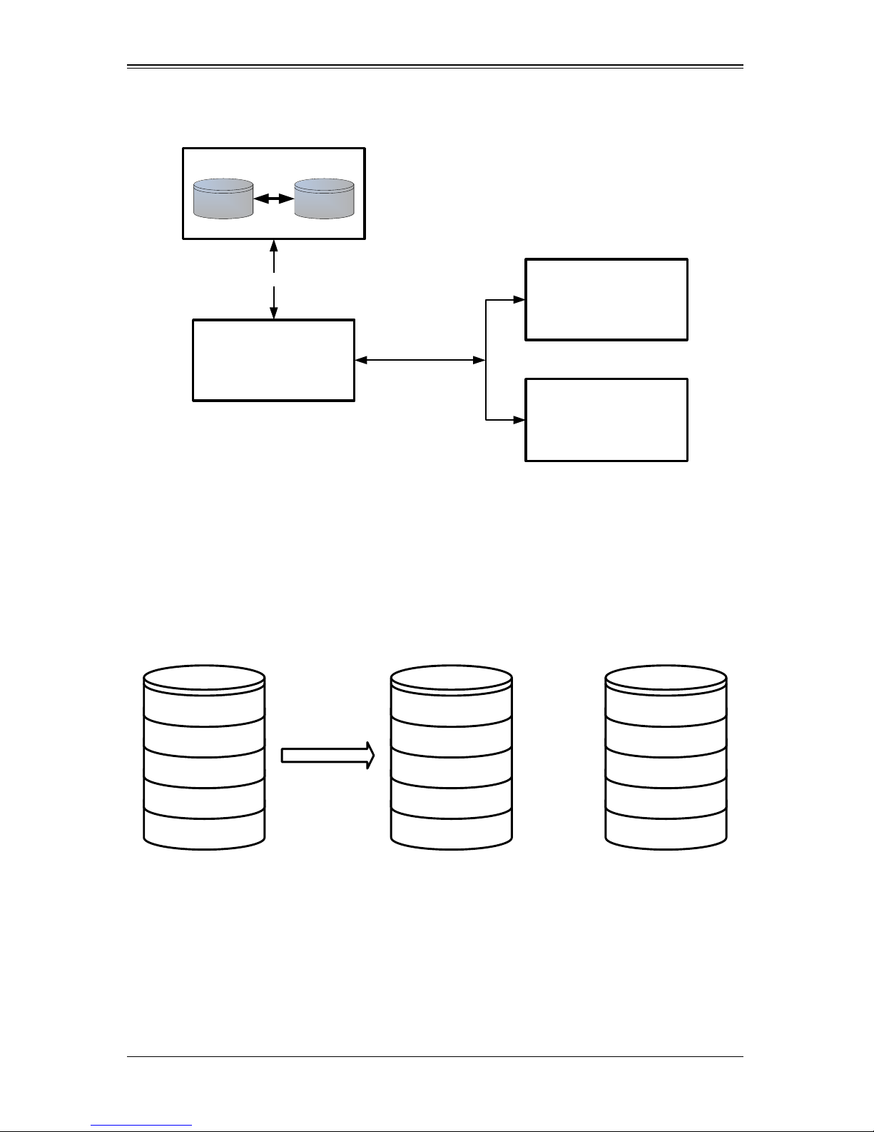
these volumes is the boot volume, as shown in Figure 4-1. Boot support is available
through the firmware of the SAS controller that supports the standard Fusion-MPT
interface. The runtime mirroring of the boot disk is transparent to the BIOS, drivers, and
operating system. Host-based status software monitors the state of the mirrored disks
and reports any error conditions. Figure 4-1 shows an IM implementation with a second
disk as a mirror of the first (primary) disk.
4-2
Page 25
Chapter 4: Integrated Mirroring and Integrated Mirroring Enhanced
IM Volume
Primary
Mirror
LSI Fusion -MPT
Controller
NVSRAM
(For Write
Journaling )
Flash
(For C onfigura tio n )
Memory B us
SAS
LBA N
...
LBA N
LBA 3
LBA 2
LBA 1
...
LBA 3
LBA 2
LBA 1
LBA N
...
LBA 3
LBA 2
LBA 1
Logical Vi ew Physical View
+
Figure 4-1. Typical Integrated Mirroring Implementation
The advantage of an IM/IME volume is that there is always a second, mirrored copy of
the data. The disadvantage is that writes take longer because data must be written
twice. On the other hand, performance is actually improved during reads.
Figure 4-2 shows the logical view and physical view of an IM volume.
Figure 4-2. Integrated Mirroring Volume
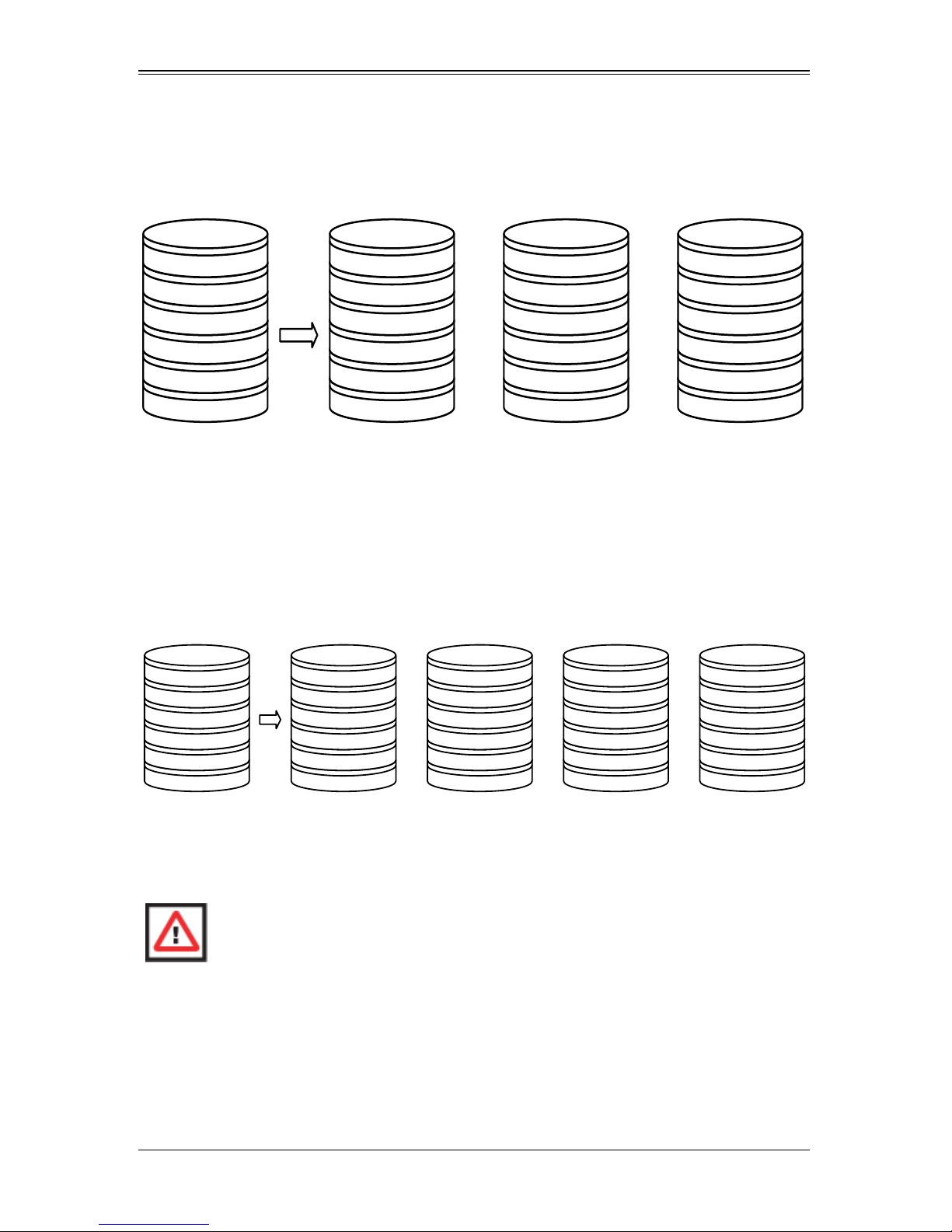
An IME volume can be configured with up to ten mirrored disks. (One or two global hot
spares can be added also.) Figure 4-3 shows the logical view and physical view of an
Integrated Mirroring Enhanced (IME) volume with three mirrored disks. Each mirrored
stripe is written to a disk and mirrored to an adjacent disk. This type of configuration is
also called RAID 1E.
4-3
Page 26
AOC-USAS2-L8i/L8e Add-on Card User’s Manual
Logical View Physical View
+ +
Mirrored Stripe N
. . .
Mirrored Stripe 4
Mirrored Stripe 3
Mirrored Stripe 2
Mirrored Stripe 1
Mirrored Stripe N-1'
. . .
Mirrored Stripe 5'
Mirrored Stripe 4
Mirrored Stripe 2'
Mirrored Stripe 1
Mirrored Stripe N
. . .
Mirrored Stripe 6
Mirrored Stripe 4'
Mirrored Stripe 3
Mirrored Stripe 1'
Mirrored Stripe N’
. . .
Mirrored Stripe 6'
Mirrored Stripe 5
Mirrored Stripe 3'
Mirrored Stripe 2
Logical Vi ew Physical View
+ +
Mirrored Stripe N
. . .
Mirrored Stripe 4
Mirrored Stripe 3
Mirrored Stripe 2
Mirrored Stripe 1
Mirrored Stripe N-1
. . .
Mirrored Stripe 7
Mirrored Stripe 5
Mirrored Stripe 3
Mirrored Stripe 1
Mirrored Stripe N-1'
. . .
Mirrored Stripe 7'
Mirrored Stripe 5'
Mirrored Stripe 3'
Mirrored Stripe 1'
Mirrored Stripe N
. . .
Mirrored Stripe 8
Mirrored Stripe 6
Mirrored Stripe 4
Mirrored Stripe 2
+
Mirrored Stripe N’
. . .
Mirrored Stripe 8'
Mirrored Stripe 6'
Mirrored Stripe 4'
Mirrored Stripe 2'
Figure 4-3. Integrated Mirroring Enhanced with Three Disks
You can configure an Integrated Mirroring and Striping volume with an even number of
disks, ranging from four minimum to ten maximum. Figure shows the logical view and
physical view of an Integrated Mirroring and Striping volume with four mirrored disks.
The firmware writes each mirrored stripe to a disk and mirrors it to an adjacent disk.
RAID 10 is another term for this type of mirrored/striped configuration.
Figure 4-4. Integrated Mirroring and Striping with Four Disks
The SAS2 BIOS-based configuration utility enables you to create mirrored volumes
during initial setup and to reconfigure them in response to hardware failures or changes
in the environment.
WARNING: All existing data on the disks is deleted when you select disk drives
to use for mirrored arrays.
4-4 Mirrored Volume Features
This section describes features of Integrated Mirroring, Integrated Mirroring andStriping,
and Integrated Mirroring Enhanced volumes. You can configure up to two mirrored
volumes on each SAS2 controller.
4-4
Page 27

Chapter 4: Integrated Mirroring and Integrated Mirroring Enhanced
Resynchronization with Concurrent Host I/O Operation
The Integrated RAID firmware allows host I/Os to continue on a mirrored volume while
the volume is being resynchronized in the background. The firmware automatically
starts resynchronizing data after a disk failure activates a hot spare, or after a physical
disk in a mirrored volume has been hot swapped.
Hot Swapping
The Integrated RAID firmware supports hot swapping, and it automatically
resynchronizes the hot-swapped disk in the background without any host or user
intervention. The firmware detects hot-swap removal and disk insertion.
Following a hot-swap event, the firmware verifies that the new physical disk has enough
capacity for the mirrored volume. The firmware resynchronizes all replaced
hot-swapped disks, even if the same disk is re-inserted. In a mirrored volume with an
even numbers of disks, the firmware marks the hot-swapped disk as a secondary disk
and the other disk with data as the primary disk. The firmware resynchronizes all data
from the primary disk onto the new secondary disk. In a mirrored volume with an odd
number of disks, primary and secondary sets include three disks instead of two.
Hot Spare Disk
You can configure two disks as global hot spare disks to protect data on the mirrored
volumes configured on the SAS2 controller. If the Integrated RAID firmware fails one of
the mirrored disks, it automatically replaces the failed disk with a hot spare disk and then
resynchronizes the mirrored data. The firmware automatically receives a notification
when a hot spare replaces the failed disk, and it then designates that disk as the new
hot spare.
Online Capacity Expansion
The OCE feature enables you to expand the capacity of an existing two-disk Integrated
Mirroring (RAID1) volume by replacing the original disk drives with larger drives that
have the same protocol (SAS or SATA).
NOTE: The new drives must be at least 50 GB larger than the original drives of
the volume.
After you replace the disk drives and run the Online Capacity Expansion command, you
must use a commercial tool specific to the operating system to move or increase the
size of the partition on the volume.
4-5
Page 28

AOC-USAS2-L8i/L8e Add-on Card User’s Manual
Media Verification
The Integrated RAID firmware supports a background media verification feature that
runs at regular intervals when the mirrored volume is in optimal state. If the verification
command fails for any reason, the firmware reads the other disk’s data for this segment
and writes it to the failing disk in an attempt to refresh the data. The firmware
periodically writes the current media verification logical block address to nonvolatile
memory so the media verification can continue approximately where it left off prior to a
power cycle.
Disk Write Caching
By default, the Integrated RAID firmware disables disk write caching for mirrored
volumes. It does this to assure that the write journal entry stored in non-volatile static
RAM (NVSRAM) is always valid. If disk write caching were enabled (not recommended),
the disk write log could be invalid.
NVSRAM Usage
The Integrated RAID firmware requires at least a 32-KB NVSRAM to perform write
journaling for mirrored volumes on LSI SAS2 controllers. The NVSRAM also preserves
configuration information across reboots. The firmware uses write journaling to verify
that the disks in the mirrored volume are synchronized with each other.
Background Initialization
Background initialization (BGI) is the process of copying data from primary to secondary
disks in a mirrored volume. The Integrated RAID firmware starts BGI automatically as a
background task when it creates a volume. The volume remains in Optimal state while
BGI is in progress.
Consistency Check
A consistency check is the process of reading data from primary and secondary disks in
a mirrored volume and comparing it to make sure it is identical. You can use the SAS2
BIOS Configuration Utility to start a consistency check on a mirrored volume.
Make Data Consistent
Make data consistent (MDC) is an optional background task similar to a consistency
check. If enabled, the Integrated RAID firmware starts MDC automatically when you
move a redundant volume from one SAS controller to another SAS controller. MDC
verifies that data on the primary and secondary disks is the same.
4-6
Page 29

Chapter 4: Integrated Mirroring and Integrated Mirroring Enhanced
4-5 Creating Mirrored Volumes
The LSI™ SAS2 BIOS Configuration Utility can be used to conf igure one or two
Integrated Mirroring, Integrated Mirroring and Striping, and Integrated Mirroring
Enhanced volumes on each SAS2 controller.
The utilility can also be used to configure one mirrored volume and one Integrated
Striping volume on the same controller, for up to a maximum of fourteen physical disk
drives for the two volumes. This includes up to two optional hot spare disks for the
mirrored volume(s).
WARNING: You cannot combine both SATA and SAS physical disks in the same
volume. All disks in the same volume must be either SATA (with extended
command set support) or SAS (with SMART support).
However you can create one volume made up of SAS disks and one volume of
SATA disks on the same controller.
NOTE: You must use 512-byte block disks that are not removable media for the
LSI SAS2 BIOS Configuration Utility.
NOTE: You need two disks for Integrated Mirroring volumes, three to ten disks
for Integrated Mirroring Enhanced volumes and four to ten even numbered
disks for Integrated Mirroring and Striping volumes.
NOTE: It is recommended that you create global hot spare disks for all mirrored
volumes for your data protection. Failed mirrored volumes are rebuilt by the
Integrated RAID firmware using these global hot spares to make the data safe.
If one of a pair of mirrored volumes fails on a SAS2 controller, then either of
them can use the global hot spares.
Starting the LSI SAS2 BIOS Configuration Utility
Use the following procedure for bringing up the SAS2 BIOS Configuration Utility:
1. Boot the system.
2. Start the SAS2 BIOS Configuration Utility by pressing C
message about the LSI Configuration Utility.
The A
DAPTER LIST window appears after the following message appears on the screen:
Please wait, invoking SAS Configuration Utility...
If the message below appears
TRL+C when you see a
LSI Corp Configuration Utility will load following
initialization!
the A
DAPTER LIST window appears after the system completes its power-on self test.
4-7
Page 30

AOC-USAS2-L8i/L8e Add-on Card User’s Manual
Creating an Integrated Mirroring Volume
Follow the steps below in order to create a two-disk Integrated Mirroring (RAID 1)
volume with the SAS2 BIOS Configuration Utility. The steps begin with the A
window that appears when the configuration utility starts.
You can navigate through this window, and others in the utility, by using the arrow keys
on your keyboard.
DAPTER LIST
1. In the A
DAPTER LIST window, select a SAS adapter and then press ENTER.
The ADAPTER PROPERTIES window appears.
2. Use the arrow keys to select RAID PROPERTIES, and then press ENTER.
The CREATE ARRAY window appears.
3. Select CREATE RAID 1 VOLUME.
The CREATE NEW ARRAY window appears.
4. Move the cursor to the RAID DISK column and select a line that has a No entry in
this column, indicating that the disk is not already part of the volume being created.
To add the disk to the new array, change the No to Yes by pressing the space bar.
This is the Primary disk in the array.
NOTE: If any of the disks contains dat a that you want to keep, back it up before
you start creating the volume. The utility deletes all data from a disk when you
select it to use in a mirrored volume.
5. Move the cursor to another line and press the space bar to add the second disk to
the array.
This is the Secondary disk in the array.
6. Press C to create the array.
A menu screen appears.
7. From the menu options, select S
AVE CHANGES then exit this menu.
A Processing message appears briefly, and then the SAS2 BIOS Configuration
Utility returns to the A
DAPTER PROPERTIES window. Initialization of the new array
continues in the background.
NOTE: To create a second Integrated Mirroring volume, repeat these
instructions starting with step 2. Alternatively, follow the instructions in the next
section to create an Integrated Mirroring Enhanced or Integrated Mirroring and
Striping volume.
NOTE: See the instructions in Section : "Creating Hot Spare Disks" on
page 4-11, if you want to create one or two global hot spares.
4-8
Page 31

Chapter 4: Integrated Mirroring and Integrated Mirroring Enhanced
Creating an Integrated Mirroring Enhanced or Integrated
Mirroring and Striping Volume
Integrated Mirroring Enhanced volumes can have from three-to-ten physical disks. Data
is written to a disk and mirrored on an adjacent disk. Integrated Mirroring and Striping
volumes can have a minimum of four and a maximum of ten physical disks, in even
numbers. In an Integrated Mirroring Enhanced or Integrated Mirroring and Striping
volume, the data is both mirrored and striped.
Follow these steps to create an Integrated Mirroring Enhanced (RAID 1E) or Integrated
Mirroring and Striping (RAID 10) volume with the SAS2 BIOS Configuration Utility.
1. On the A
press E
DAPTER LIST window, use the arrow keys to select a SAS adapter and then
NTER.
The ADAPTER PROPERTIES window appears.
2. Use the arrow keys to select RAID PROPERTIES, and then press ENTER.
The CREATE ARRAY window appears.
3. Select CREATE RAID 1E VOLUME.
The CREATE NEW ARRAY window appears.
4. Move the cursor to the RAID DISK column and select a line that has a No entry in
this column, indicating that the disk is not already part of the volume being created.
To add the disk to the new array, change the No to Yes by pressing the space bar.
5. Move the cursor to another line and press the space bar to add another disk to the
array .
If you select an odd number of disks, the SAS2 BIOS Configuration Utility creates
an Integrated Mirroring Enhanced array. If you select an even number of disks, it
creates an Integrated Mirroring and Striping array . As you add disks, the A
RRAY SIZE
field changes to reflect the size of the new array.
6. Press C to create the array.
A menu screen appears.
7. From the menu options, select S
A Processing message appears briefly, and then the SAS2 BIOS Configuration
Utility returns to the A
continues in the background.
NOTE: To create a second Integrated Mirroring Enhanced or Integrated
Mirroring and Striping volume, repeat the instructions above.
AVE CHANGES then exit this menu.
DAPTER PROPERTIES window. Initialization of the new array
4-9
Page 32

AOC-USAS2-L8i/L8e Add-on Card User’s Manual
NOTE: See the instructions in Section : "Creating Hot Spare Disks" on
page 4-11, if you want to create one or two global hot spares.
Expanding an Integrated Mirroring Volume with OCE
You can use the online capacity expansion (OCE) feature to expand the capacity of a
two-disk Integrated Mirroring (RAID1) volume by replacing the original disks with two
larger disk drives while the volume remains online. This process maintains data integrity
at all times, even if one of the disks fails during the replacement process. The new disks
must be at least 50 GB larger than the disks they are replacing, and they must use the
same protocol (SAS or SATA) as the disks they are replacing.
Follow these steps to expand an existing RAID1 volume with OCE:
1. Physically replace one of the two volume disk drives with a drive that is at least 50
GB larger.
If necessary , you can identify the disks in the volume by following the instructions in
"Locating Disk Drives in a Volume".
2. Wait until synchronization is complete on the new disk and the volume returns to the
Optimal state, as indicated in the A
DAPTER PROPERTIES window of the SAS2 BIOS
Configuration Utility.
3. Physically replace the other volume disk drive with a drive that is at least 50 GB
larger.
4. Again, wait until synchronization is complete on the new disk and the volume
returns to the Optimal state.
5. In the A
keys to select the SAS adapter with the RAID1 volume and then press E
DAPTER LIST window of the SAS2 BIOS Configuration Utility, use the arrow
NTER.
The ADAPTER PROPERTIES window appears.
6. Use the arrow keys to select RAID PROPERTIES, and then press ENTER.
ELECT NEW ARRAY TYPE window appears.
The S
7. Select VIEW EXISTING ARRAY.
The V
IEW ARRAY window appears. If necessary, press Alt + N to switch to the
RAID1 volume with the new, larger disk drives.
8. Select M
ANAGE ARRAY.
The MANAGE ARRAY window appears.
9. Select ONLINE CAPACITY EXPANSION.
A menu screen appears with a warning message and with options to start the
expansion process or quit.
10. Press Y to start the expansion.
4-10
Page 33

Chapter 4: Integrated Mirroring and Integrated Mirroring Enhanced
The RAID PROPERTIES screen appears when the expansion process is complete.
This typically occurs in a very short amount of time.
1 1. Run a commercial tool specific to the operating system to move or increase the size
of the partition on the newly-expanded RAID1 volume.
4-6 Hot Sp are Disks
You can create one or two global hot spare disks to protect the data on mirrored
volumes on a SAS2 controller. You can also delete hot spare disks.
Creating Hot Spare Disks
Follow these steps to add global hot spare disks to an existing volume. The steps begin
with the A
1. In the ADAPTER LIST window, use the arrow keys to select the SAS adapter with the
DAPTER LIST window that appears when the configuration utility starts:
volume that needs hot spare disks and then press E
NTER.
The ADAPTER PROPERTIES window appears.
2. Use the arrow keys to select RAID PROPERTIES, and then press ENTER.
The SELECT NEW ARRAY TYPE window appears.
3. Select VIEW EXISTING ARRAY.
The VIEW ARRAY window appears. If necessary, press Alt + N to switch to another
array on this adapter.
4. Select M
ANAGE ARRAY.
The MANAGE ARRAY window appears.
5. Select MANAGE HOT SPARES, which is the first option.
The MANAGE HOT SPARES window appears.
6. Identify a disk that is not part of a RAID volume (such as the value in the DRIVE
S
TATUS column is not RAID) and that is not already identified as a hot spare disk.
NOTE: A global hot spare disk must have 512-byte blocks and nonremovable
media. The disk type must be either SATA with extended command set support
or SAS with SMART support.
7. Move the highlight to the H
OT SPR (HOT SPARE) field for this disk and press the
space bar.
The Hot Spare status changes to Yes.
8. (Optional) Repeat the preceding step to select a second global hot spare disk
9. Press C to create the hot spare disk.
A menu window appears. An error message appears if the selected disk is not at
least as large as the smallest disk used in the existing volume(s). An error message
4-11
Page 34

AOC-USAS2-L8i/L8e Add-on Card User’s Manual
also appears if you try to add a SATA disk as a hot spare for volumes that use SAS
disks, or vice versa.
10. Select S
The SAS2 BIOS Configuration Utility pauses while it configures the global hot
spares.
AVE CHANGES then exit this menu to create the hot spare disk(s).
Deleting Hot Spare Disks
Follow these steps to delete a global hot spare disk:
1. Access the Manage Hot Spares window by following step 1 through step 5 of
"Creating Hot Spare Disks".
2. Select the disk that you no longer wish to use as a hot spare, and press C.
3. Select S
The configuration utility pauses while it removes the global hot spare.
AVE CHANGES then exit this menu to commit the changes.
4-7 Other Configuration Tasks
This section explains how to perform other configuration and maintenance tasks for
mirrored volumes.
Viewing Volume Properties
Follow these steps to view the RAID properties of the mirrored volume(s):
1. In the SAS2 BIOS Configuration Utility, select a SAS2 adapter from the ADAPTER
L
IST.
The ADAPTER PROPERTIES window appears.
2. Select RAID PROPERTIES.
The SELECT NEW ARRAY TYPE window appears.
3. Select VIEW EXISTING ARRAY.
The VIEW ARRAY window appears, showing information about the array and each
disk in it. The window includes hot spare information, if you have created global hot
spare disks.
NOTE: If you create one volume using SAS disks, another volume using SATA
disks, and global hot spare disks, the hot spare disks only appear when you
view the mirrored volume that uses the same type of disks as the hot spare
disks.
4. If the currently displayed array is not the one you want, press Alt+N to view another
array on the adapter.
4-12
Page 35

Chapter 4: Integrated Mirroring and Integrated Mirroring Enhanced
Running a Consistency Check
Use the Consistency Check command to verify that the data is synchronized on the
mirrored disks in the volume.
Follow these steps to run a consistency check on a selected mirrored volume:
1. In the A
DAPTER LIST window, use the arrow keys to select a SAS adapter.
The ADAPTER PROPERTIES window appears.
2. Use the arrow keys to select RAID P
The S
ELECT NEW ARRAY TYPE window appears.
ROPERTIES, and then press ENTER.
3. Select VIEW EXISTING ARRAY.
The VIEW ARRAY window appears. If necessary, press Alt + N to switch to another
array on this adapter.
4. S
ELECT MANAGE ARRAY.
The MANAGE ARRAY window appears.
5. Select CONSISTENCY CHECK in the MANAGE ARRAY window.
A menu window appears.
6. Press Y to start the consistency check.
The consistency check runs a read-read-compare algorithm in the background. If it
encounters any data miscompares, it stores the information in a bad block table.
Activating an Array
A volume (array) can become inactive if, for example, you remove it from one controller
or computer and install it on a different one. The Activate Array option allows you to
reactivate an inactive volume. This option is available only when the selected volume is
currently inactive.
Follow these steps to activate a selected volume:
1. In the A
E
NTER.
DAPTER LIST window, use the arrow keys to select a SAS adapter and press
The ADAPTER PROPERTIES window appears.
2. Select RAID PROPERTIES, and then press ENTER.
The SELECT NEW ARRAY TYPE window appears.
3. Select VIEW EXISTING ARRAY.
The VIEW ARRAY window appears. If necessary, press Alt + N to switch to another
array on this adapter.
4. Select M
ANAGE ARRAY.
The MANAGE ARRAY window appears.
4-13
Page 36
AOC-USAS2-L8i/L8e Add-on Card User’s Manual
5. Select ACTIVATE ARRAY in the MANAGE ARRAY window.
A menu window appears.
6. Press Y to activate the array.
The array becomes active after a pause.
Deleting an Array
WARNING: Before you delete an array, be sure to back up all data on the array
that you want to keep.
Follow these steps to delete a selected volume (array):
1. In the ADAPTER LIST window, use the arrow keys to select a SAS adapter.
The ADAPTER PROPERTIES window appears.
2. Use the arrow keys to select RAID PROPERTIES, and then press ENTER.
The SELECT NEW ARRAY TYPE window appears.
3. Select VIEW EXISTING ARRAY.
The VIEW ARRAY window appears. If necessary, press Alt + N to switch to another
array on this adapter.
4. Select M
The MANAGE ARRAY window appears.
5. Select DELETE ARRAY.
A menu window appears.
6. Press Y to delete the array, or press N to cancel the deletion process.
After a pause, the utility deletes the array. If there is another remaining array and
one or two hot spare disks, the BIOS checks the hot spare disks to determine if they
are compatible with the remaining volume. If they are not compatible (too small or
wrong disk type), the BIOS deletes them also.
ANAGE ARRAY.
Locating Disk Drives in a Volume
You can use the SAS2 BIOS Configuration Utility to locate and identify a specific
physical disk drive in a disk enclosure by flashing the drive’s LED. You can also flash the
LEDs of all the disk drives in a RAID volume, if they are in a disk enclosure.
When you add a disk drive to a new mirrored volume, the LED on the disk drive starts
flashing. The LED stops flashing when you finish creating the volume.
4-14
Page 37

Chapter 4: Integrated Mirroring and Integrated Mirroring Enhanced
You can locate individual disk drives from the SAS Topology window by flashing their
LEDs. To do this, follow these steps:
1. Select the desired SAS2 controller on the A
DAPTER LIST window and press ENTER.
The ADAPTER PROPERTIES window appears.
2. Highlight SAS TOPOLOGY and press ENTER.
The SAS TOPOLOGY window appears.
3. Select the disk in the DEVICE IDENTIFIER column and press ENTER.
The LED on the disk flashes until you press a key to stop it.
4. To identify all the disk drives in a volume, select the volume in the left column of the
SAS T
OPOLOGY window and press ENTER.
The LEDs flash on all disk drives in the volume until you press a key to stop them.
NOTE: The LEDs on the disk drives will flash as described above if the
firmware is correctly configured and the drives are in a disk enclosure.
Selecting a Boot Disk
You can select a boot disk in the SAS TOPOLOGY window. The next time you boot the
computer, the firmware moves this disk to scan ID 0, making it the new boot disk. This
makes it easier to set BIOS boot device options and to keep the boot device constant
during device additions and removals. You can also select an alternative boot device. If
the BIOS cannot find the preferred boot device when it loads, it will attempt to boot from
the alternate device.
Follow these steps to select a boot disk:
1. In the SAS2 BIOS Configuration Utility, select an adapter from the A
DAPTER LIST.
2. Select the SAS TOPOLOGY option. If a device is currently configured as the boot
device, the D
EVICE INFO column on the SAS TOPOLOGY window lists the word Boot.
If a device is currently configured as the alternate boot device, the DEVICE INFO
column shows the word Alt.
3. To select the preferred boot disk, move the cursor to the disk and press Alt+B.
4. To remove the boot designator, move the cursor to the current boot disk and press
Alt+B.
This controller will no longer have a disk designated as boot.
5. To change the boot disk, move the cursor to the new boot disk and press Alt+B.
The Boot designator moves to this disk.
6. To select an alternate boot disk, move the cursor to the disk and press Alt+A.
4-15
Page 38

AOC-USAS2-L8i/L8e Add-on Card User’s Manual
NOTE: To change the alternate boot device from one disk to another, follow
step 4 and step 5 above, but use Alt+A instead of Alt+B.
4-16
Page 39

Chapter 5
Integrated Striping
This chapter provides an overview of the LSI Integrated Striping™ (IS) feature and
explains how to create Integrated Striping (IS) volumes using the SAS2 BIOS
Configuration Utility, which is used to setup IR Mode.
NOTE: Integrated Striping is also known as RAID 10.
5-1 Introduction
Integrated RAID enables you to create Integrated Striping volumes for applications that
require the faster performance and increased storage capacity of striping. The low-cost
Integrated Striping feature has many of the advantages of a more expensive RAID
striping solution. You can configure an Integrated Striping volume as the boot disk or as
a data disk.
The Integrated Striping solution provides better performance and more capacity than
individual disks, without burdening the host CPU. The firmware splits host I/Os over
multiple disks and presents the disks as a single logical drive. In general, striping is
transparent to the BIOS, the drivers, and the operating system.
You use the SAS2 BIOS Configuration Utility t o configure Integrated Striping volumes.
These volumes can consist of two-to-ten disks.
5-1
Page 40

AOC-USAS2-L8i/L8e Add-on Card User’s Manual
5-2 IS Features
Integrated Striping supports the following features:
• Support for volumes with two to ten disks
• Support for two Integrated Striping volumes with up to 14 drives total on a SAS2
controller.
• Support for combining one Integrated Striping volume and one Integrated Mirroring,
Integrated Mirroring + Striping, or Integrated Mirroring Enhanced volume on a single
controller.
• Support for both SAS and SATA drives, although the two types of drives cannot be
combined in one volume
• Fusion-MPT architecture
• Easy-to-use SAS BIOS configuration utility
• Error notification
• Disk write caching, which is enabled by default on all Integrated Striping volumes
• Use of metadata to store volume configuration on disks
• OS-specific event log
• Error display inside the Fusion-MPT BIOS
• SCSI Enclosure Services (SES) status LED support for drives used in Integrated
Striping volumes
5-3 IS Description
The IS feature writes data across multiple disks instead of onto one disk. This is
accomplished by partitioning each disk’s storage space into 64-KB stripes. These
stripes are interleaved round-robin, so that the combined storage space is composed
alternately of stripes from each disk.
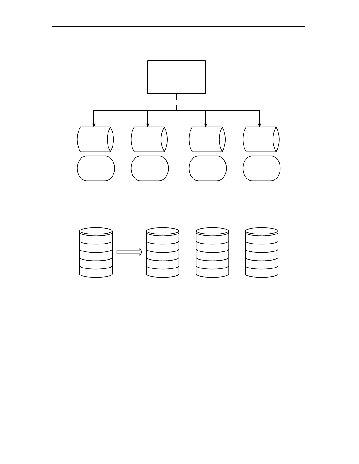
For example, as shown in Figure 5-1, segment 1 is written to disk 1, segment 2 is written
to disk 2, segment 3 is written to disk 3, and so on. When the system reaches the end of
the disk list, it continues writing data at the next available segment of disk 1.
5-2
Page 41
Chapter 5: Integrated Striping
LSI
Fusion-MPT
Cont ro ller
Dis k 1 Disk 2 Disk 3 Disk 4
Segment 1
Segment 5
Segment 9
Segment 2
Segment 6
Segment 10
Segment 3
Segment 7
Segment 11
Segment 4
Segment 8
Segment 12
SAS
Logical View Physical View
+
Stripe N
...
Stripe 3
Stripe 2
Stripe 1
Stripe N
...
Stripe 3
Stripe 2
Stripe 1
Stripe N
...
Stripe 3
Stripe 2
Stripe 1
Stripe N
...
Stripe 3
Stripe 2
Stripe 1
+
Figure 5-1. Integrated Striping Example
Figure 5-2 shows a logical view and a physical view of Integrated Striping configuration.
Figure 5-2. Integrated Striping – Logical and Physical Views
The primary advantage of IS is speed, because it transfers data to or from multiple disks
at once. However, there is no data redundancy; therefore, if one disk fails, that data is
lost.
5-4 Integrated Striping Firmware
This section describes features of the Integrated RAID firmware.
Me tada ta Support
The firmware supports metadata, which describes the IS logical drive configuration
stored on each member disk. When the firmware is initialized, each member disk is
queried to read the stored metadata to verify the configuration. The usable disk space
for each IS member disk is adjusted down when the configuration is created, in order to
leave room for this data.
5-3
Page 42

AOC-USAS2-L8i/L8e Add-on Card User’s Manual
SMART Support
SMART is a technology that monitors hard disk drives for signs of future disk failure and
generates an alert if such signs are detected. The firmware polls each physical disk in
the volume at regular intervals. If the firmware detects a SMART ASC/ASCQ code on a
physical disk in the IS volume, it processes the SMART data and stores it in nonvolatile
memory. The IS volume does not support SMART directly, since it is just a logical
representation of the physical disks in the volume.
Disk Write Caching
Disk write caching is enabled by default on all IS volumes.
5-5 Fusion-MPT Support
The BIOS uses the LSI Fusion-MPT interface to communicate to the SAS controller and
firmware to enable IS. This includes reading the Fusion-MPT configuration to gain
access to the parameters that are used to define behavior between the SAS controller
and the devices connected to it. The Fusion-MPT drivers for all supported operating
systems implement the Fusion-MPT interface to communicate with the controller and
firmware.
5-6 IS Configuration Overview
The SAS2 BIOS Configuration Utility is a menu-driven utility program that enables you
to easily configure and manage Integrated RAID volumes. Y ou can use the SAS2 BIOS
Configuration Utility to create one or two Integrated Striping volumes on each SAS2
controller. Each volume can have from two-to-ten drives. All disks in an Integrated
Striping volume must be connected to the same SAS2 controller.
Although you can use disks of different size in Integrated Striping volumes, the smallest
disk in the volume determines the logical size of all disks in the volume. In other words,
the firmware does not use the excess space of the larger member disk(s). For example,
if you create an Integrated Striping volume with two 100-GB disks and two 120-GB
disks, the firmware uses only 100 GB on each of the larger disks for the volume. The
supported stripe size is 64 kilobytes.
5-7 Creating IS Volumes
The SAS2 BIOS Configuration Utility is part of the Fusion-MPT BIOS. When the BIOS
loads during boot and you see the message about the Configuration Utility, press Ctrl-C
to start it. After you do this, the message changes to:
Please wait, invoking SAS Configuration Utility...
After a brief pause, the main menu of the SAS2 BIOS CU appears. On some systems,
however, the following message appears next:
LSI Configuration Utility will load following initialization!
5-4
Page 43

Chapter 5: Integrated Striping
In this case, the SAS2 BIOS Configuration Utility will load after the system has
completed its power-on self test.
You can configure any combination of up to two Integrated Striping (RAID 0) volumes
and mirrored volumes on each SAS2 controller, up to a maximum of 14 physical disk
drives for the two volumes. (This includes one or two hot spare disks for mirrored
arrays.)
The following guidelines apply when creating an Integrated Striping volume:
• All physical disks in an Integrated Striping volume must be either SATA (with
extended command set support) or SAS (with SMART support). You cannot
combine SAS and SATA disks in the same volume. However, you can create one
volume with SAS disks and a second volume with SATA disks on the same
controller.
• Disks must have 512-byte blocks and must not have removable media.
• Integrated Striping volumes must have at least two disks and no more than 10 disks.
Integrated Striping volumes do not support hot spare disks.
Follow the steps below to configure an Integrated Striping (IS) volume with the SAS2
BIOS Configuration Utility. The procedure assumes that the required controller(s) and
disks are already installed in the computer system.
Creating IS Volumes
1. On the A
keys to select a SAS adapter and press E
DAPTER LIST screen of the SAS2 BIOS Configuration Utility, use the arrow
NTER.
The ADAPTER PROPERTIES screen appears.
2. Select RAID PROPERTIES and press ENTER.
The CREATE ARRAY window appears.
3. Select CREATE RAID 0 VOLUME.
The CREATE NEW ARRAY window appears.
4. Move the cursor to the RAID DISK column and select a line that has a No entry in
this column, indicating that the disk is not already part of the volume being created.
To add the disk to the new array, change the No to Yes by pressing the space bar.
5. Move the cursor to another line and press the space bar to add another disk to the
array .
6. Continue adding disks in this way until you have added the number you want.
7. Press C to create the array.
A menu appears.
8. From the menu options, select S
A Processing message appears briefly, and then the SAS2 BIOS Configuration
Utility returns to the A
continues in the background.
AVE CHANGES then exit this menu.
DAPTER PROPERTIES window. Initialization of the new array
5-5
Page 44

AOC-USAS2-L8i/L8e Add-on Card User’s Manual
NOTE: Repeat the instructions above to create a second Integrated Striping
volume, if desired and if enough additional disks are available.
5-8 Other Configuration Tasks
This section explains how to perform other configuration and maintenance tasks for IS
volumes.
Viewing IS Volume Properties
Follow these steps to view the properties of IS volumes:
1. In the SAS2 BIOS Configuration Utility, select an SAS adapter from the ADAPTER
L
IST.
The ADAPTER PROPERTIES window appears.
2. Select RAID PROPERTIES.
The SELECT NEW ARRAY TYPE window appears.
3. Select VIEW EXISTING ARRAY.
The VIEW ARRAY window appears, showing information about the array and each
disk in it.
4. If the currently displayed array is not the one you want, press Alt+N to view another
array on the adapter.
Activating an Array
An array can become inactive if, for example, it is removed from one controller or
computer and moved to another one. The A
reactivate an inactive array that has been added to a system. This option is only
available when the selected array is currently inactive.
Follow these steps to activate a selected array.
1. In the A
E
DAPTER LIST window, use the arrow keys to select an SAS adapter and press
NTER.
The ADAPTER PROPERTIES window appears.
2. Select RAID PROPERTIES, and then press ENTER.
CTIVATE ARRAY option allows you to
The SELECT NEW ARRAY TYPE window appears.
3. Select VIEW EXISTING ARRAY.
The VIEW ARRAY window appears. If necessary, press Alt + N to switch to another
array on this adapter.
4. Select M
ANAGE ARRAY.
5-6
Page 45
Chapter 5: Integrated Striping
The MANAGE ARRAY window appears.
5. Select ACTIVATE ARRAY in the MANAGE ARRAY window.
A menu window appears.
6. Press Y to activate the array.
The array becomes active after a pause.
Deleting an Array
WARNING: Before deleting an array, be sure to back up all data on the array that
you want to keep.
Follow these steps to delete a selected array:
1. In the ADAPTER LIST window, use the arrow keys to select an SAS adapter.
The ADAPTER PROPERTIES window appears.
2. Use the arrow keys to select RAID PROPERTIES, and then press ENTER.
The SELECT NEW ARRAY TYPE window appears.
3. Select VIEW EXISTING ARRAY.
The VIEW ARRAY window appears. If necessary, press Alt + N to switch to another
array on this adapter.
4. Select M
The MANAGE ARRAY window appears.
5. Select DELETE ARRAY.
A menu window appears.
6. Press Y to delete the array, or press N to cancel the deletion process.
After a pause, the utility deletes the array.
ANAGE ARRAY.
Locating a Disk in a Volume
You can use the SAS2 BIOS Configuration Utility to locate and identify a specific
physical disk drive in a disk enclosure by flashing the drive’s LED. You can also flash the
LEDs of all the disk drives in a RAID volume, if they are in a disk enclosure.
When you add a disk drive to a new mirrored volume, the LED on the disk drive starts
flashing. The LED stops flashing when you finish creating the volume.
5-7
Page 46

AOC-USAS2-L8i/L8e Add-on Card User’s Manual
You can locate individual disk drives from the SAS Topology window by flashing their
LEDs. To do this, follow these steps:
1. Select the desired SAS2 controller on the A
DAPTER LIST window and press ENTER.
The ADAPTER PROPERTIES window appears.
2. Highlight SAS TOPOLOGY and press ENTER.
The SAS TOPOLOGY window appears.
3. Select the disk in the DEVICE IDENTIFIER column and press ENTER.
The LED on the disk flashes until you press a key to stop it.
4. To identify all the disk drives in a volume, select the volume in the left column of the
SAS T
OPOLOGY window and press ENTER.
The LEDs flash on all disk drives in the volume until you press a key to stop them.
NOTE: The LEDs on the disk drives will flash as described above if the
firmware is correctly configured and the drives are in a disk enclosure.
Selecting a Boot Disk
You can select a boot disk in the SAS TOPOLOGY window. The next time you boot the
computer, the firmware moves this disk to scan ID 0, making it the new boot disk. This
makes it easier to set BIOS boot device options and to keep the boot device constant
during device additions and removals. You can also select an alternative boot device. If
the BIOS cannot find the preferred boot device when it loads, it will attempt to boot from
the alternate device.
Follow these steps to select a boot disk:
1. In the SAS2 BIOS Configuration Utility, select an adapter from the A
DAPTER LIST.
2. Select the SAS TOPOLOGY option. If a device is currently configured as the boot
device, the D
EVICE INFO column on the SAS TOPOLOGY window lists the word Boot.
If a device is currently configured as the alternate boot device, the DEVICE INFO
column shows the word Alt.
3. To select the preferred boot disk, move the cursor to the disk and press Alt+B.
4. To remove the boot designator, move the cursor to the current boot disk and press
Alt+B.
This controller will no longer have a disk designated as boot.
5. To change the boot disk, move the cursor to the new boot disk and press Alt+B.
The Boot designator moves to this disk.
6. To select an alternate boot disk, move the cursor to the disk and press Alt+A.
5-8
Page 47

Chapter 5: Integrated Striping
NOTE: To change the alternate boot device from one disk to another, follow
step 4 and step 5 above, but use Alt+A instead of Alt+B.
5-9
Page 48

AOC-USAS2-L8i/L8e Add-on Card User’s Manual
5-10
Page 49

Chapter 6
Using the Configuration Utility
SAS2IRCU is a command-line utility that you use to configure the Integrated RAID
functions of SAS2 controllers. SAS2IRCU runs in the DOS, Linux, EFI, and Windows
Pre-Installation (WinPE) environments. It is a minimally interactive program that you can
execute from a command-line prompt or a shell script. When you use SAS2IRCU
commands, the program sends results to the environment through the program status
value that it returns when it exits.
Typical uses for this utility include, but are not limited to, system configuration on the
manufacturing floor, post-delivery configuration by end users, and ongoing configuration
and monitoring of Integrated RAID devices.
NOTE: SAS2IRCU is a configuration utility for the manufacturing environment.
End users should use the SAS2 BIOS Configuration Utility to create and
manage Integrated RAID volumes. See Chapter 4: "Integrated Mirroring and
Integrated Mirroring Enhanced" on page 4-1 and Chapter 5: "Integrated
Striping" on page 5-1 for further details.
6-1 Hardware and Software Requirements
SAS2IRCU runs on the following platforms.
• X86 - X86 or compatible
• EFI - UEFI 2
• EM64T/AMD64
• Sun SPARC® (v9)
SAS2IRCU works with storage devices that are compliant with existing SCSI standards.
SAS2IRCU requires PCI 2.x or PCI 3.0 firmware and MPI v2.0. SAS2IRCU supports the
following operating systems:
• WinPE 1.x (Server 2003/XP), WinPE 2.0 (Vista), WinPE 2.1 (Server 2008) Requires
Windows® driver v2.00.00.17 or greater.
• UEFI 2.1 Linux® 2.6 Kernel - RHEL 5, SLES 10 Requires Linux driver
v00.255.04.00 or greater.
• MS-DOS® 6.22 and FreeDOS 1.0
SAS2IRCU runs on DOS only if the system BIOS supports 32-bit BIOS services,
including the PCI BIOS services. SAS2IRCU uses these services to locate the controller
and its interface registers because it needs to directly access the controller chip’s
interface registers.
6-1
Page 50

AOC-USAS2-L8i/L8e Add-on Card User’s Manual
6-2 Commands and Interface Description
Format commands as follows for the SAS2IRCU command-line interface:
sas2ircu <controller #> <command> <parameters>
Use a space to separate the program name, controller number, command, and
parameters fields. The format of <parameters> is command specific.
Information passes between the user environment and the SAS2IRCU through the
command line, the standard output and standard error interfaces, and the program
return value. You can redirect the output streams as permitted by the operating system.
When the program exits, it returns a value of 0 if the command is successful. Otherwise,
it returns a value of 1.
If a RAID command fails, the SAS2IRCU prints the IOCStatus and IOCLogInfo on the
console. You can use this information to analyze the cause of the failure.
The following table shows which commands the SAS2IRCU supports on each operating
system.
Table 6-1. SASIRCU Comman ds
Command DOS Linux EFI WinPE
CREATE XXXX
DELETE X X X X
DISPLAY XXXX
HOTSPARE X X X X
LIST XXXX
STATUS X X X X
MFGPAGE X--CONSTCHK X X X X
ACTIVATE XXXX
LOCATE X X X X
LOGIR XXXX
The commands are not case sensitive. The command descriptions use the following
conventions:
• Enter the text in italics exactly as shown on the command line.
• Replace text enclosed in < > with a required parameter.
• Replace text enclosed in [ ] with an optional parameter.
• Enter parameters enclosed in { } one or more times, as required for the command
being executed.
• Do not enter the command-line definition characters < >, [ ], and { } on the command
line.
6-2
Page 51

Chapter 6: Using the Configuration Utility
Common Command-Line Parameters
This section describes command-line parameters that are common to more than one
command.
• <controller #>
The unique controller number that the program assigns to each PCI function found
on supported controller chips in the system, starting with controller # 0. For
example, in a system containing two controllers, controller # 0 references the first
controller and controller # 1 references the other controller. Valid controller number
• <Enclosure:Bay>
The enclosure and bay/slot of a peripheral device attached to the bus. The
argument must use a colon (:) as a separator and must follow the enclosure:bay
format. Enclosure is a 16-bit EnclosureHandle value set by the IOC. A value of 0 is
invalid. Bay/Slot is a 16-bit slot value set by the IOC. Use the DISPLAY command to
get the enclosure and slot numbers of a drive.
CREATE Command
The CREATE command creates Integrated RAID volumes on SAS2 controllers.
When you add a disk to an Integrated RAID volume, some of its storage capacity may
not be used. For example, if you add a 300-GB disk drive to a volume that only uses 200
GB of capacity on each disk drive, the volume does not use the remaining 100 GB of
capacity on the disk drive.
The disk identified by the first Enclosure:Bay on the command line becomes the primary
disk drive when you create an Integrated Mirroring (RAID 1) volume. If the controller
resyncs the disk drives, the data on the primary disk drive becomes available when you
access the newly created volume.
When the IR firmware creates a RAID1 volume, it starts a background initialization of the
volume. You can use the STATUS command to monitor the status of the initialization.
Observe the following rules when creating Integrated RAID volumes and hot spare
disks:
• All disks that are part of a volume, including hot spares for that volume, must be on
the same SAS2 controller.
• You can create RAID0, RAID1, RAID1E, and RAID10 Integrated RAID volumes.
• You can create a maximum of two Integrated RAID volumes per controller.
• The configuration of the Integrated RAID firmware determines the maximum and
minimum number of drives that you can use in Integrated RAID volumes.
The configuration is specified in the following fields of IOC Page 6:
MaxDrivesRAID0, MaxDrivesRAID1, MaxDrivesRAID10, MaxDrivesRAID1E
MinDrivesRAID0, MinDrivesRAID1, MinDrivesRAID10, MinDrivesRAID1E,
MaxVolumes, MaxPhysDisks, MaxGlobalHotSpares, MaxPhysDisks (maximum
number of physical drives combined in all volumes on the controller)
6-3
Page 52

AOC-USAS2-L8i/L8e Add-on Card User’s Manual
For more information, see the description of the IOC configuration pages in Chapter
14 of the Fusion MPT 2.0 MPI Specification Guide.
• SAS2IRCU does not allow you to create an Integrated RAID volume that combines
SAS and SATA HDDs.
• SAS2IRCU does not allow you to create an Integrated RAID volume that combines
SSDs (solid-state drives) and hard disk drives.
• SAS2IRCU does allow you to use both SATA and SAS solid-state drives in a single
Integrated RAID volume, if the Integrated RAID firmware supports it.
Support for such a mixing is specified by values in static fields in Manufacturing
Page 4 in the MPI2 specification and is specific for SSD drives only.
Command Line
sas2ircu <controller #> create <volume type> <size>
{<enclosure:bay>} [VolumeName] [noprompt]
Parameters
• <controller #> – The index of the controller for the newly-created volume.
• <volume type> – Volume type for the new volume. Valid values are RAID0, RAID1,
RAID10, or RAID1E.
• <size> – Size of the RAID volume in Mbytes, or MAX for the maximum size
available.
• <enclosure:bay> - The enclosure:bay value of the disk drive for the new RAID
volume.You can get these values from the output of the DISPLAY command. DOS
does not support addressing by enclosure:bay.
• VolumeName – A user-specified string to identify the volume.
• noprompt – This optional parameter prevents warnings and prompts from appearing
while the command is running.
Program Return Value
0x00 SUCCESS: Command completed successfully.
0x01 FAILURE: Bad command-line arguments or operational failure.
0x02 ADAPTER_NOT_FOUND: Cannot find specified adapter.
DELETE Command
The DELETE command deletes all Integrated RAID volumes and hot spare drives from
the specified LSI SAS2 controller. No other controller configuration parameters are
changed.
Command Line
sas2ircu <controller #> delete [noprompt]
6-4
Page 53

Chapter 6: Using the Configuration Utility
Parameters
• <controller #> – The index of the controller with the volume(s) that you want to
delete.
• noprompt – This optional parameter prevents warnings and prompts from appearing
while the command is running.
Program Return Value
0x00 SUCCESS: Command completed successfully.
0x01 FAILURE: Bad command-line arguments or operational failure.
0x02 ADAPTER_NOT_FOUND: Cannot find specified adapter.
DISPLAY Command
The DISPLA Y command displays information about LSI SAS2 controller configurations,
including controller type, firmware version, BIOS version, volume information, physical
drive information, and enclosure. See the following Sample Output example.
The physical device information section displays the duplicate device of a dual ported
SAS drive.
NOTE: One MB is 1,048,576 bytes. The command rounds all amounts stated in
MB down to the nearest MB.
Command Line
sas2ircu <controller #> display [filename]
Parameters
• <controller #> – The index of the controller for which you want to display
information.
• [filename] – An optional valid filename to store the command output to a file.
Program Return Value
0x00 SUCCESS: Command completed successfully.
0x01 FAILURE: Bad command-line arguments or operational failure.
0x02 ADAPTER_NOT_FOUND: Cannot find specified adapter.
6-5
Page 54

AOC-USAS2-L8i/L8e Add-on Card User’s Manual
Sample Output
Here is a sample of the information that the DISPLAY command returns.
Read configuration has been initiated for controller 0
-----------------------------------------------------------Controller information
-----------------------------------------------------------Controller type : SAS2008
BIOS version : 7.00.02.00
Firmware version : 00.250.19.0
Channel description : 1 Serial Attached SCSI
Initiator ID : 112
Maximum physical devices : 62
Concurrent commands supported : 266
Slot : 3
Segment : 0
Bus : 64
Device : 1
Function : 0
RAID Support : Yes
-----------------------------------------------------------IR Volume information
------------------------------------------------------------
-----------------------------------------------------------Physical device information
-----------------------------------------------------------Initiator at ID #112
Device at ID #335524
Device is a Hard disk
Enclosure # : 2
Slot # : 2
Connector ID : 4
State : Ready (RDY)
Size (in MB)/(in sectors) : 70007/143374738
Manufacturer : HP
Model Number : DG072A9BB7
Firmware Revision : HPD0
Serial No : B365P720H7330709
Protocol : SAS
Drive Type : SAS
Device at ID #335525
6-6
Page 55

Chapter 6: Using the Configuration Utility
Device is a Hard disk
Enclosure # : 2
Slot # : 1
Connector ID : 4
State : Ready (RDY)
Size (in MB)/(in sectors) : 70007/143374738
Manufacturer : HP
Model Number : DG072A9BB7
Firmware Revision : HPD0
Serial No : B365P720H7L70709
Protocol : SAS
Drive Type : SAS
-----------------------------------------------------------Enclosure information
-----------------------------------------------------------Enclosure# : 1
Logical ID : 51234567:89012345
Numslots : 8
StartSlot : 0
Values
Logical drive status values are as follows:
• Okay (OKY) – The volume is Active and drives are functioning properly. User data
is protected if the current RAID level provides data protection.
• Degraded (DGD) – The volume is Active. User data is not fully protected due to a
configuration change or drive failure.
• Failed (FLD) – The volume has failed.
• Missing (MIS) – The volume is missing.
• Initializing (INIT) – The volume is initializing.
• Online (ONL) – The volume is online.
Physical device status values are as follows:
• Online (ONL) – The drive is operational and is part of a logical drive.
• Hot Spare (HSP) – The drive is a hot spare that is available to replace a failed
drive in an array.
• Ready (RDY) – The drive is ready for use as a normal disk drive, or it is ready to
be assigned to a disk array or a hot spare pool.
• Available (AVL) – The drive may or may not be ready, and it is not suitable for
use in an array or a hot spare pool.
• Failed (FLD) – The drive was part of a logical drive or was a hot spare drive, and
it failed. The drive is now offline.
6-7
Page 56

AOC-USAS2-L8i/L8e Add-on Card User’s Manual
• Missing (MIS) – The drive was part of a logical drive or was a hot spare drive,
and it is missing. It has been removed or is not responding.
• Standby (SBY) – The device is not a hard disk device.
• Out of Sync (OSY) – The drive, which is part of a logical drive, is not in sync with
other drives that are part of the logical drive.
• Degraded (DGD) – The drive is part of a logical drive and is in degraded state.
• Rebuilding (RBLD) – The drive is part of a logical drive and is currently
rebuilding.
• Optimal (OPT) – The drive is optimal and is part of a logical drive.
Physical device Drive Type values are as follows:
• SAS_HDD – The drive is a SAS hard-disk drive (HDD).
• SATA_HDD – The drive is a SATA hard-disk drive (HDD).
• SAS_SSD – The drive is a SAS solid-state drive (SSD).
• SATA_SSD – The drive is a SATA solid-state drive (SSD).
Physical device Protocol values are as follows:
• SAS – The drive supports SAS protocol.
• SATA – The drive supports SATA protocol.
HOTSPARE Command
The HOTSPARE command adds a hot spare drive to spare pool 0 or deletes a hot spare
drive. The capacity of the hot spare drive must be greater than or equal to the capacity
of the smallest drive in the RAID volume. You can verify this by using the DISPLAY
command on the drive.
Observe the following rules when creating hot spare disks:
• You cannot create a hot spare disk unless at least one RAID1, RAID10, or RAID1E
volume already exists.
• You cannot create a hot spare and add it to an inactive Integrat ed RAID volume.
• For hard-disk drives, you cannot add a SAS hot spare disk if the existing volumes on
the controller use SATA disks. You cannot add a SATA hot spare disk if the existing
volumes on the controller use SAS disks.
• For solid-state drives only, you can add a SAS hot spare SSD to a volume with
SA TA SSDs and you can add a SATA hot spare SSD to a volume with SAS SSDs, if
the Integrated RAID firmware allows it.
This depends on the values in the static fields in Manufacturing Page 4. For more
information, see the Fusion-MPT 2.0 MPI Specification Guide.
• The maximum allowable number of hot spare drives depends on the value of the
MaxGlobalHotSpares field in IOC P age 6. (Normally, the maximum is two global hot
spares per controller.)
• You cannot add a solid-state drive hot spare to a volume with hard-disk drives, or
vice versa.
6-8
Page 57

Chapter 6: Using the Configuration Utility
Command Line
sas2ircu <controller #> hotspare [delete] <enclosure:bay>
Parameters
• <controller #> – The index of the controller on which you want to create the hot
spare disk.
• <enclosure:bay> - The enclosure:bay value for the hot spare disk drive. You can get
these values from the output of the DISPLAY command. DOS does not support
addressing by enclosure:bay.
• delete – This optional command deletes the hot spare disk at enclosure:bay.
Program Return Value
0x00 SUCCESS: Command completed successfully.
0x01 FAILURE: Bad command-line arguments or operational failure.
0x02 ADAPTER_NOT_FOUND: Cannot find specified adapter.
STATUS Command
The STATUS command displays the current status of any existing Integrated RAID
volumes and the status of any operation that is currently in progress on the selected
controller. If no operation is in progress, the SAS2IRCU prints a message indicating thi s
before it exits.
Command Line
sas2ircu <controller #> status
Parameters
• <controller #> – The index of the controller with the volumes whose status you want
to display.
Program Return Value
0x00 SUCCESS: Command completed successfully.
0x01 FAILURE: Bad command-line arguments or operational failure.
0x02 ADAPTER_NOT_FOUND: Cannot find specified adapter.
6-9
Page 58

AOC-USAS2-L8i/L8e Add-on Card User’s Manual
Sample Output
Here is an example of the information that the STATUS command returns when a
volume resynchronization is in progress:
Background command progress status for controller 0...
IR Volume 1
Volume ID : 6
Current operation : Synchronize
Volume status : Enabled
Volume state : Degraded
Physical disk I/Os : Not quiesced
Volume size (in sectors) : 70311936
Number of remaining sectors : 68250624
Percentage complete : 2.93%
Here is an example of the status information that the STATUS command returns if a
background volume operation is not in progress:
Background command progress status for controller 0...
IR Volume 1
Current operation : None
Volume ID : 6
Volume status : Enabled
Volume state : Optimal
Physical disk I/Os : Not quiesced
Values
The possible values for the fields in the status data are as follows:
• Current operation: Synchronize, Consistency Check, OCE, Background Init, or
None
• Volume status: Enabled or Disabled
• Volume state: [Inactive] Optimal, Degraded, Missing, or Failed
• Physical disk I/Os: Quiesced or Not quiesced
LIST Command
The LIST command displays a listing of all controllers present in system, along with
each corresponding controller index. You use the controller index as an input parameter
for other SAS2IRCU commands.
Command Line
sas2ircu list
6-10
Page 59

Chapter 6: Using the Configuration Utility
Parameters
None
Program Return Value
0x00 SUCCESS: Command completed successfully.
0x01 FAILURE: Command failed.
0x02 ADAPTER_NOT_FOUND: Cannot find specified adapter.
Sample Output
Here is an example of the output of the LIST command. The format and fields in the
output may vary depending on the types of installed controllers.
Adapter
Index
0 SAS2008 1000h 72h 00h:01h:00h:00h 1000h 00dah
1 SAS2008 1000h 72h 00h:05h:00h:00h 1000h 00dah
Type
Vendor IDDevice
ID
PCI Address
SubSys
Ven ID
SubSys
Dev ID
MFGPAGE Command
The MFGP AGE command updates information on manufacturing p ages. Only DOS and
EFI support this command.
Command Line
sas2ircu <controller #> mfgpage <passcode> <mfgpage #>
<offset> <value>
Parameters
• <controller #> – The index of the controller with the manufacturing pages you want
to update.
• <passcode> – A passcode is required for DOS access, which is restricted.
• <mfgpage #> – The manufacturing page (4 or 10) that needs to be updated.
• <offset> – The dword offset in the specified manufacturing page that needs to be
updated, in hex format.
• <value> – The value for the offset that is being modified, in hex format.
Program Return Value
0x00 SUCCESS: Command completed successfully.
0x01 FAILURE: Bad command-line arguments or operational failure.
0x02 ADAPTER_NOT_FOUND: Cannot find specified adapter.
6-11
Page 60

AOC-USAS2-L8i/L8e Add-on Card User’s Manual
CONSTCHK Command
The CONSTCHK command sends requests to the Integrated RAID firmware to start a
consistency check operation on the specified volume.
Command Line
sas2ircu <controller #> constchk <volumeId> [noprompt]
Parameters
• <controller #> – The index of the controller on which the consistency check
operation needs to run.
• <volumeId> – The volume ID of an Integrated RAID volume, as listed in the
DISPLAY command, on which the consistency check operation needs to start.
• noprompt – This optional parameter prevents warnings and prompts from appearing
while the command is running.
Program Return Value
0x00 SUCCESS: Command completed successfully.
0x01 FAILURE: Bad command-line arguments or operational failure.
0x02 ADAPTER_NOT_FOUND: Cannot find specified adapter.
ACTIVATE Command
The ACTIVATE command activates an inactive Integrated RAID volume.
Command Line
sas2ircu <controller #> activate <volumeId>
Parameters
• <controller #> – The index of the controller with the volume that needs to be
activated.
• <volumeId> – The volume ID of an Integrated RAID volume currently in the Inactive
state.
Program Return Value
0x00 SUCCESS: Command completed successfully.
0x01 FAILURE: Bad command-line arguments or operational failure.
0x02 ADAPTER_NOT_FOUND: Cannot find specified adapter.
6-12
Page 61

Chapter 6: Using the Configuration Utility
LOCATE Command
The LOCATE command locates specific drives in a volume by turning on their location
indicator.
Command Line
sas2ircu <controller #> locate <Encl:Bay> <action>
Parameters
• <controller #> – The index of the controller with the drives that you need to locate.
• <Encl:Bay> – The Enclosure and Bay number of the drive.
• <action> – The possible actions are as follows:
• ON – Turn on the location indicator of the drive.
• OFF – Turn off the location indicator of the drive.
Program Return Value
0x00 SUCCESS: Command completed successfully.
0x01 FAILURE: Bad command-line arguments or operational failure.
0x02 ADAPTER_NOT_FOUND: Cannot find specified adapter.
LOGIR Command
The LOGIR command uploads or clears the Integrated RAID log information.
Command Line
sas2ircu <controller #> logir <action> [filename] [noprompt]
Parameters
• <controller #> – The index of the controller with the logs that you need to upload or
clear.
• <action> – The possible actions are as follows:
• UPLOAD – Upload the controller logs to a file.
• CLEAR – Clear the controller logs.
• filename – This optional parameter specifies the filename where the logs need to be
• noprompt – This optional parameter prevents warnings and prompts from appearing
while the command is running.
Program Return Value
0x00 SUCCESS: Command completed successfully.
0x01 FAILURE: Bad command-line arguments or operational failure.
0x02 ADAPTER_NOT_FOUND: Cannot find specified adapter.
6-13
Page 62

AOC-USAS2-L8i/L8e Add-on Card User’s Manual
Notes
6-14
Page 63

Chapter 7
SAS2 BIOS Configuration Utility
The LSI™ SAS2 BIOS Configuration Utility is used to configure one or two Int egrated
Mirroring, Integrated Mirroring and Striping, and Integrated Mirroring Enhanced volumes
on each SAS2 controller.
The utilility can also be used to configure one mirrored volume and one Integrated
Striping volume on the same controller, up to a maximum of fourteen physical disk
drives for the two volumes. This includes up to two optional hot spare disks for the
mirrored volume(s).
WARNING: You cannot combine both SATA and SAS physical disks in the same
volume. All disks in the same volume must be either SATA (with extended
command set support) or SAS (with SMART support).
However you can create one volume made up of SAS disks and one volume of
SATA disks on the same controller.
NOTE: You must use 512-byte block disks that are not removable media for the
LSI SAS2 BIOS Configuration Utility.
NOTE: You need two disks for Integrated Mirroring volumes, three to ten disks
for Integrated Mirroring Enhanced volumes and four to ten even numbered
disks for Integrated Mirroring and Striping volumes.
NOTE: It is recommended that you create global hot spare disks for all mirrored
volumes for your data protection. Failed mirrored volumes are rebuilt by the
Integrated RAID firmware using these global hot spares to make the data safe.
If one of a pair of mirrored volumes fails on a SAS2 controller, then either of
them can use the global hot spares.
7-1 Starting the LSI SAS2 BIOS Configuration Utility
Use the following procedure for bringing up the SAS2 BIOS Configuration Utility:
1. Boot the system.
2. Start the SAS2 BIOS Configuration Utility by pressing C
message about the LSI Configuration Utility.
The A
DAPTER LIST screen appears after the following message appears on the screen:
Please wait, invoking SAS Configuration Utility...
If the message below appears
TRL+C when you see a
7-1
Page 64
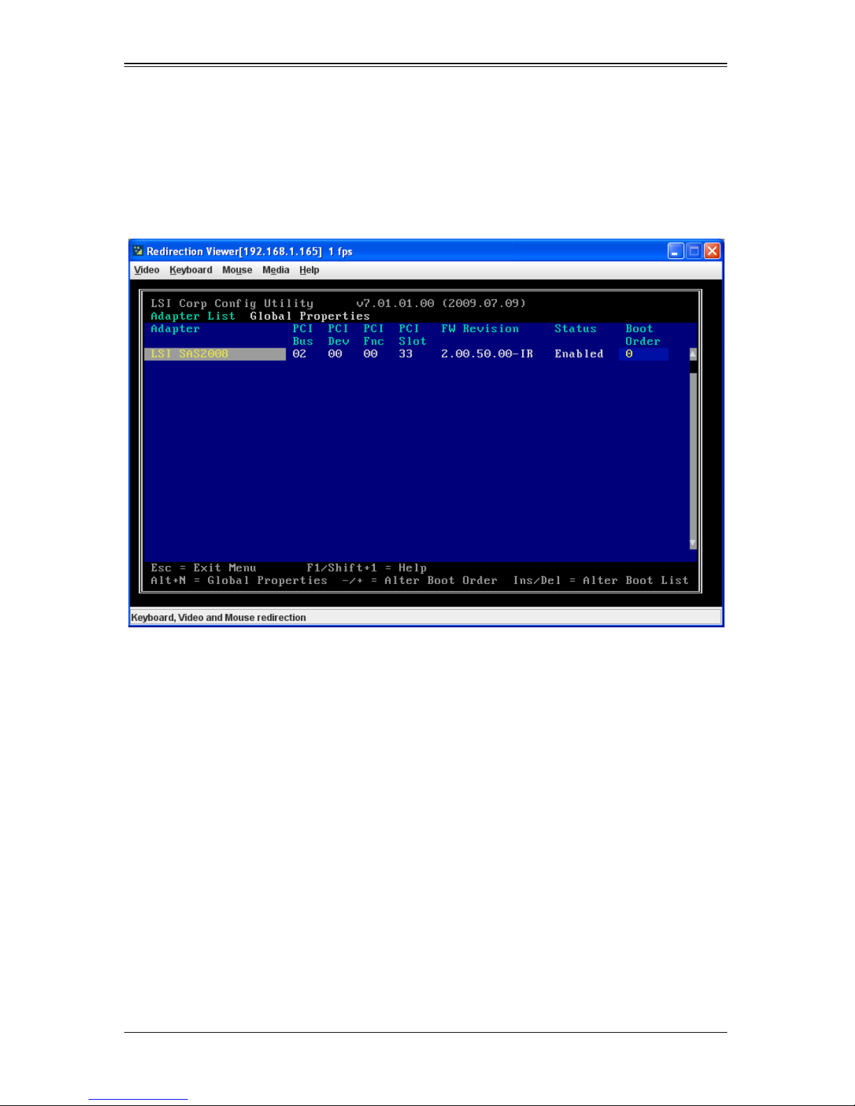
AOC-USAS2-L8i/L8e Add-on Card User’s Manual
LSI Corp Configuration Utility will load following
initialization!
the A
DAPTER LIST screen (Figure 7-1) appears after the system completes its power-on
self test.
Figure 7-1. Adapter List Screen
7-2
Page 65
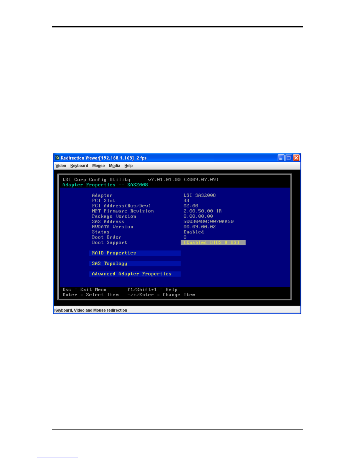
Chapter 7: SAS2 BIOS Configuration Utility
7-2 Creating a RAID 1 Volume
Follow the steps below in order to create a two-disk Integrated Mirroring (RAID 1)
volume with the SAS2 BIOS Configuration Utility. The steps begin with the A
screen that appears when the configuration utility starts.
You can navigate through this screen, and others in the utility, by using the arrow keys
on your keyboard. Use the +/- keys or the Space bar on your keyboard to change
options. To exit a screen, and go back to the previous screen, by using the E
1. In the ADAPTER LIST screen, select a SAS adapter and then press ENTER.
The ADAPTER PROPERTIES screen appears (Figure 7-2).
Figure 7-2. Adapter Properties Screen
DAPTER LIST
SC key.
7-3
Page 66
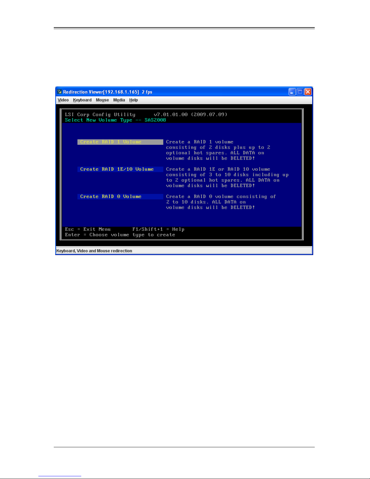
AOC-USAS2-L8i/L8e Add-on Card User’s Manual
2. Use the arrow keys to select RAID PROPERTIES, and then press ENTER.
The SELECT NEW VOLUME TYPE screen appears (Figure 7-3).
Figure 7-3. Select New Volume Type
7-4
Page 67
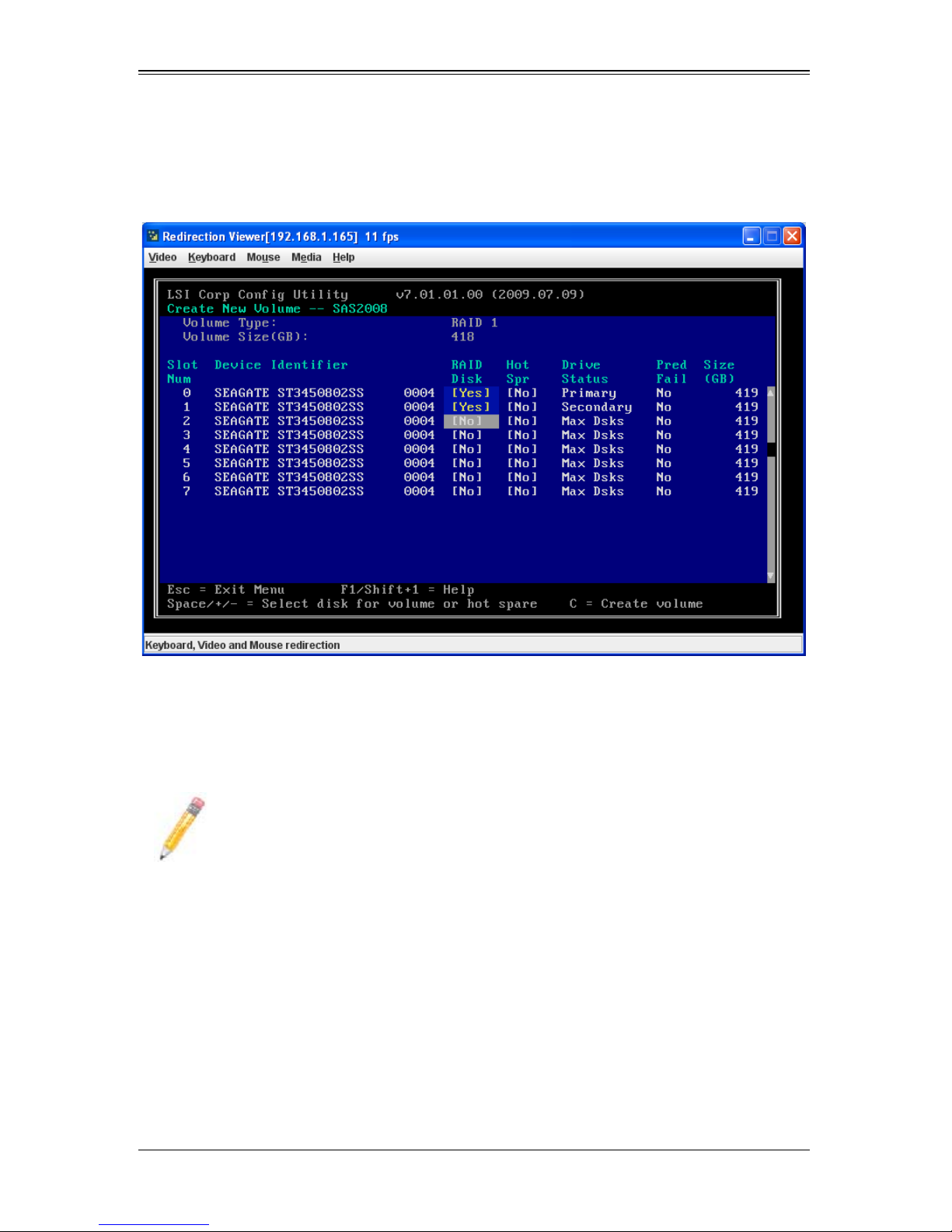
Chapter 7: SAS2 BIOS Configuration Utility
3. Select CREATE RAID 1 VOLUME.
The CREATE NEW VOLUME screen appears (Figure 7-4).
Figure 7-4. Create New Volume Screen – RAID 1
4. Move the cursor to the RAID D
ISK column and select a line that has a No entry in
this column, indicating that the disk is not already part of the volume being created.
To add the disk to the new volume, change the N
O to Yes by pressing the space bar.
This is the Primary disk in the volume.
NOTE: If any of the disks contains dat a that you want to keep, back it up before
you start creating the volume. The utility deletes all data from a disk when you
select it to use in a mirrored volume.
5. Move the cursor to another line and press the space bar to add the second disk to
the volume.
This is the Secondary disk in the volume.
7-5
Page 68
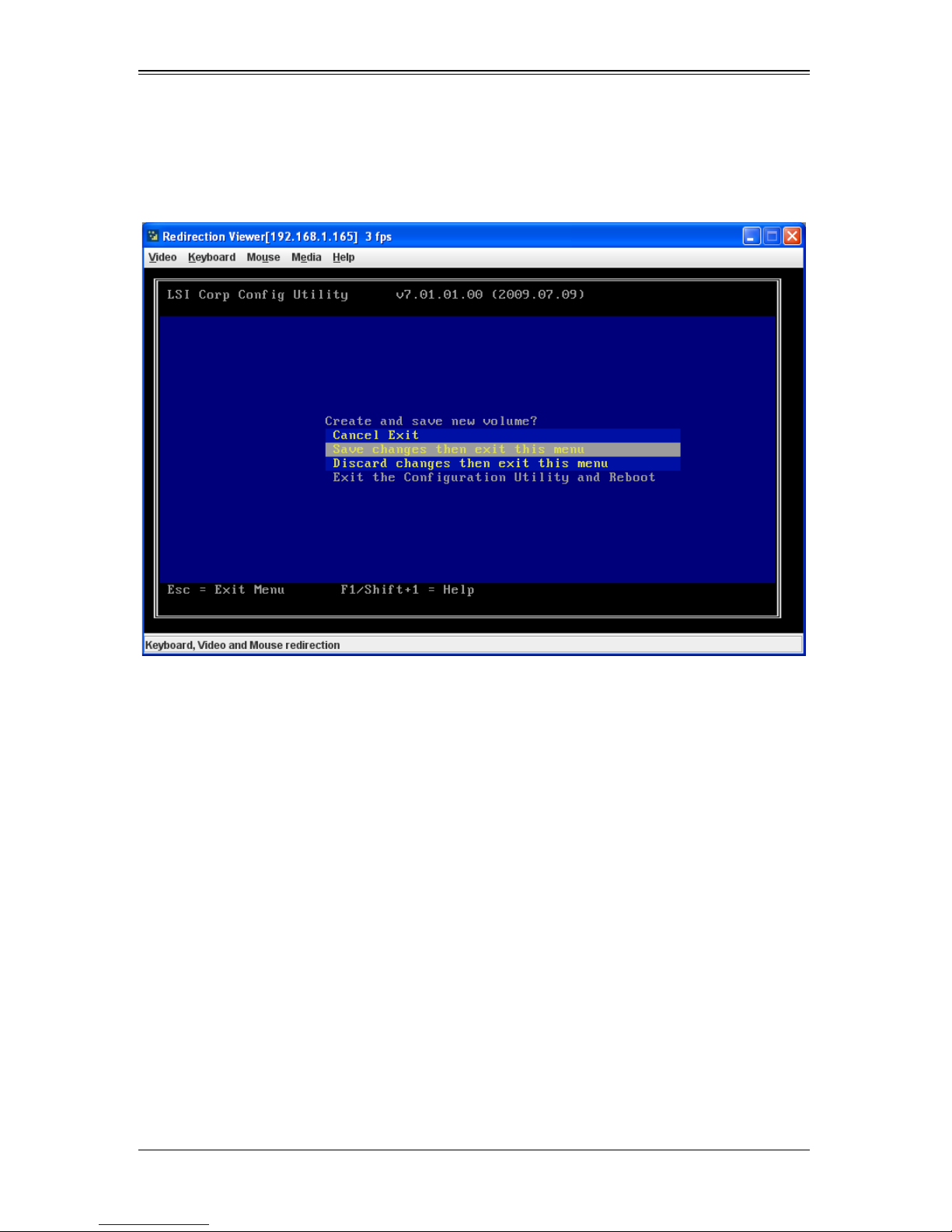
AOC-USAS2-L8i/L8e Add-on Card User’s Manual
6. Press C to create the volume.
A menu screen appears (Figure 7-5).
Figure 7-5. Menu Screen
7. From the menu options, select S
AVE CHANGES then exit this menu.
A Processing message appears briefly, and then the SAS2 BIOS Configuration
Utility returns to the A
DAPTER PROPERTIES screen. Initialization of the new volume
continues in the background.
7-6
Page 69
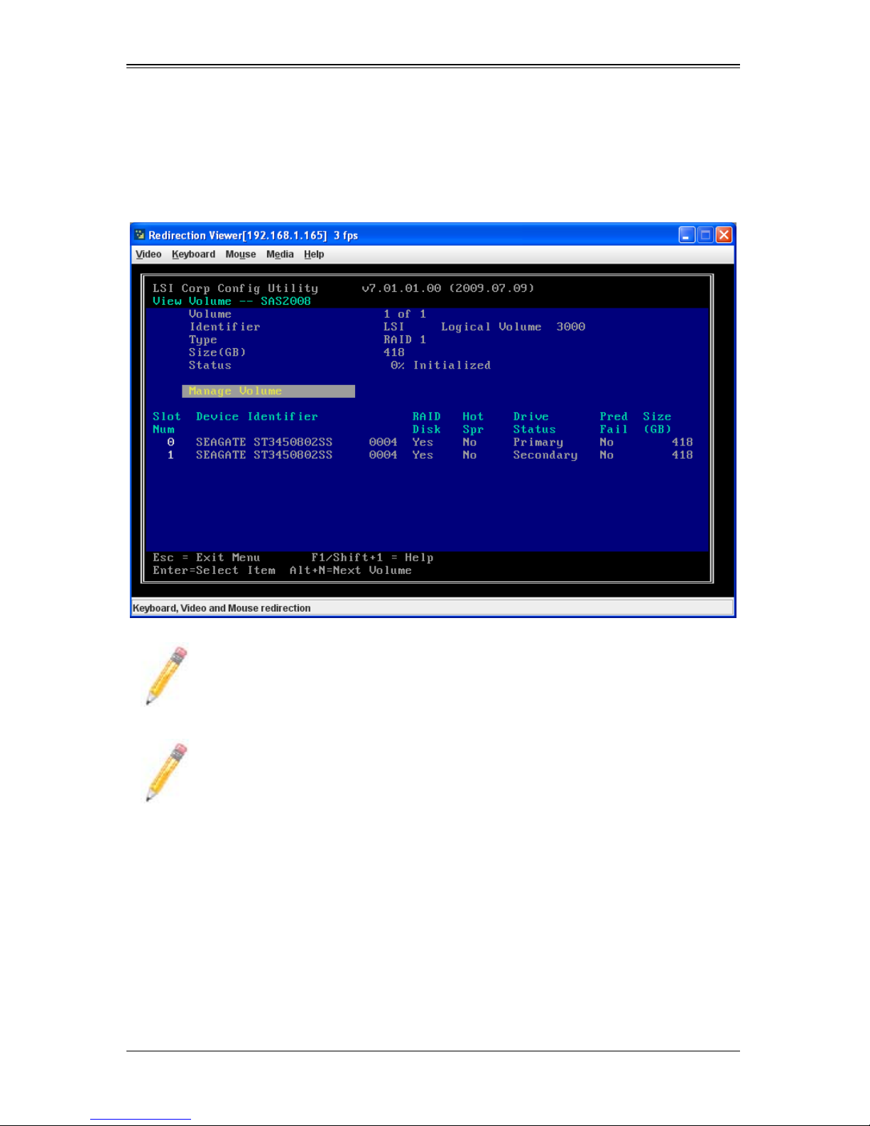
Chapter 7: SAS2 BIOS Configuration Utility
8. From the ADAPTER PROPERTIES screen, select VIEW EXISTING VOLUME.
The VIEW VOLUME screen appears (Figure 7-8). Use this screen to view your volume
details and review it for correctness.
Figure 7-6. View Volume Screen – RAID 10
NOTE: To create a second Integrated Mirroring volume, repeat these
instructions starting with step 2. Alternatively, follow the instructions in the next
section to create an Integrated Mirroring Enhanced or Integrated Mirroring and
Striping volume.
NOTE: See the instructions in Section : "Creating Hot Spare Disks" on
page 7-15, if you want to create one or two global hot spares.
7-7
Page 70
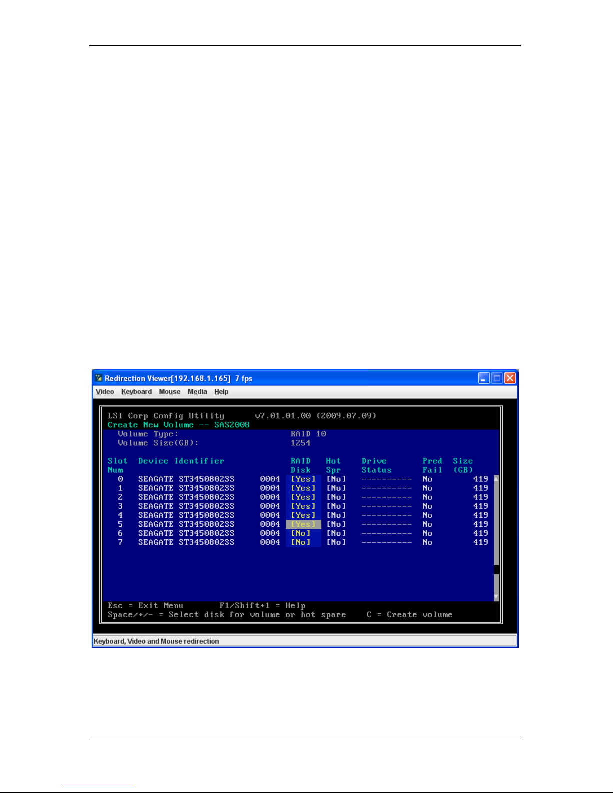
AOC-USAS2-L8i/L8e Add-on Card User’s Manual
7-3 Creating a RAID 1E or RAID 10 Volume
Integrated Mirroring Enhanced volumes can have from three-to-ten physical disks. Data
is written to a disk and mirrored on an adjacent disk. Integrated Mirroring and Striping
volumes can have a minimum of four and a maximum of ten physical disks, in even
numbers. In an Integrated Mirroring Enhanced or Integrated Mirroring and Striping
volume, the data is both mirrored and striped.
Follow these steps to create an Integrated Mirroring Enhanced (RAID 1E) or Integrated
Mirroring and Striping (RAID 10) volume with the SAS2 BIOS Configuration Utility.
1. On the A
press E
The A
DAPTER LIST screen, use the arrow keys to select a SAS adapter and then
NTER.
DAPTER PROPERTIES screen appears (see Figure 7-2).
2. Use the arrow keys to select RAID PROPERTIES, and then press ENTER.
The SELECT NEW VOLUME TYPE screen appears (see Figure 7-3).
3. Select CREATE RAID 1E/10 VOLUME.
The CREATE NEW VOLUME screen appears (Figure 7-7).
Figure 7-7. Create New Volume Screen – RAID 10
4. Move the cursor to the RAID D
this column, indicating that the disk is not already part of the volume being created.
To add the disk to the new volume, change the N
ISK column and select a line that has a No entry in
O to Yes by pressing the space bar.
7-8
Page 71
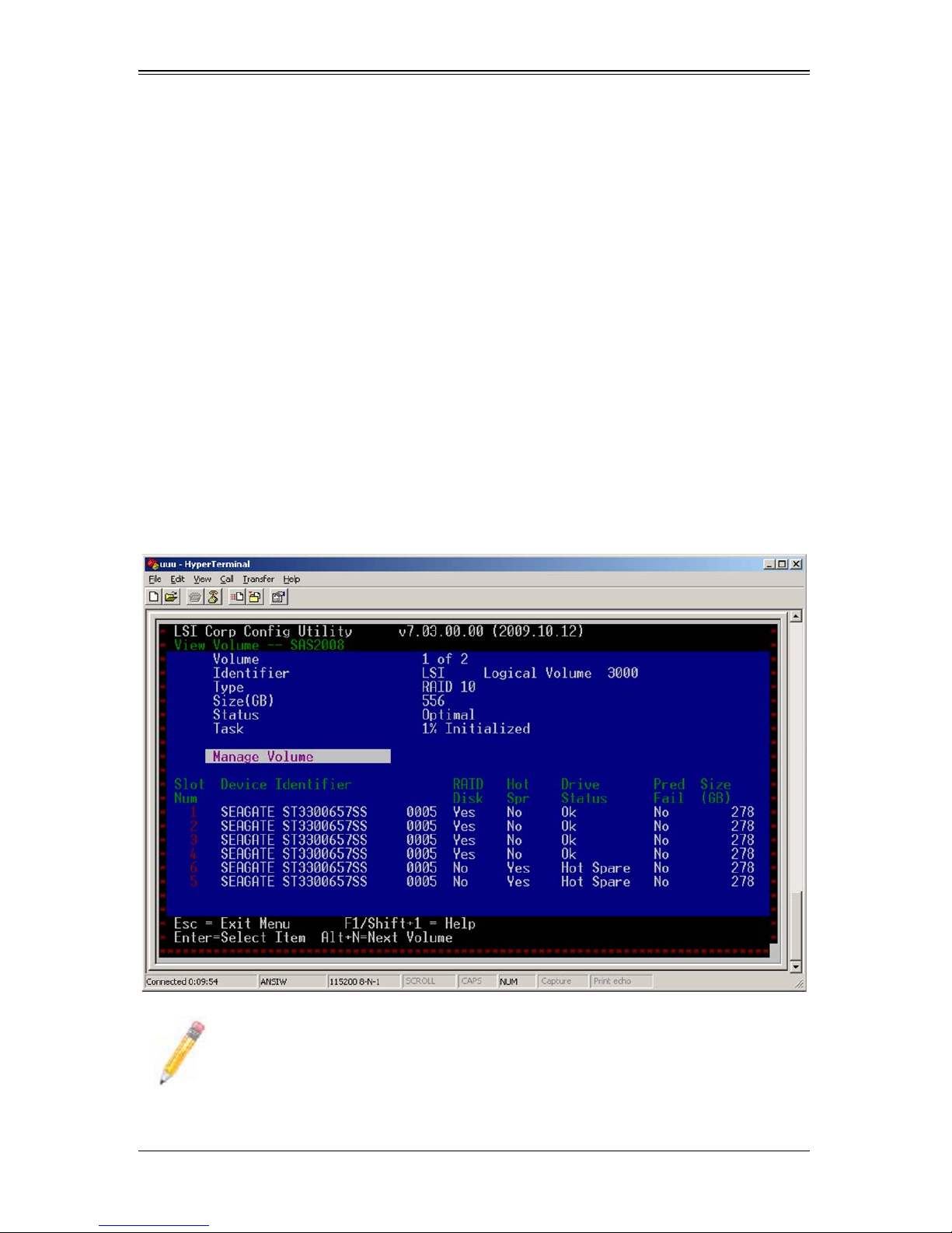
Chapter 7: SAS2 BIOS Configuration Utility
5. Move the cursor to another line and press the space bar to add another disk to the
volume.
If you select an odd number of disks, the SAS2 BIOS Configuration Utility creates
an Integrated Mirroring Enhanced volume. If you select an even number of disks, it
creates an Integrated Mirroring and Striping volume. As you add disks, the V
S
IZE field changes to reflect the size of the new volume.
6. Press C to create the volume.
A menu screen appears (see Figure 7-5).
OLUME
7. From the menu options, select S
AVE CHANGES then exit this menu.
A Processing message appears briefly, and then the SAS2 BIOS Configuration
Utility returns to the A
DAPTER PROPERTIES screen. Initialization of the new volume
continues in the background.
8. From the A
DAPTER PROPERTIES screen, select VIEW EXISTING VOLUME.
The VIEW VOLUME screen appears (Figure 7-8). Use this screen to view your volume
details and review it for correctness.
Figure 7-8. View Volume Screen – RAID 10
NOTE: To create a second Integrated Mirroring Enhanced or Integrated
Mirroring and Striping volume, repeat the instructions above.
7-9
Page 72
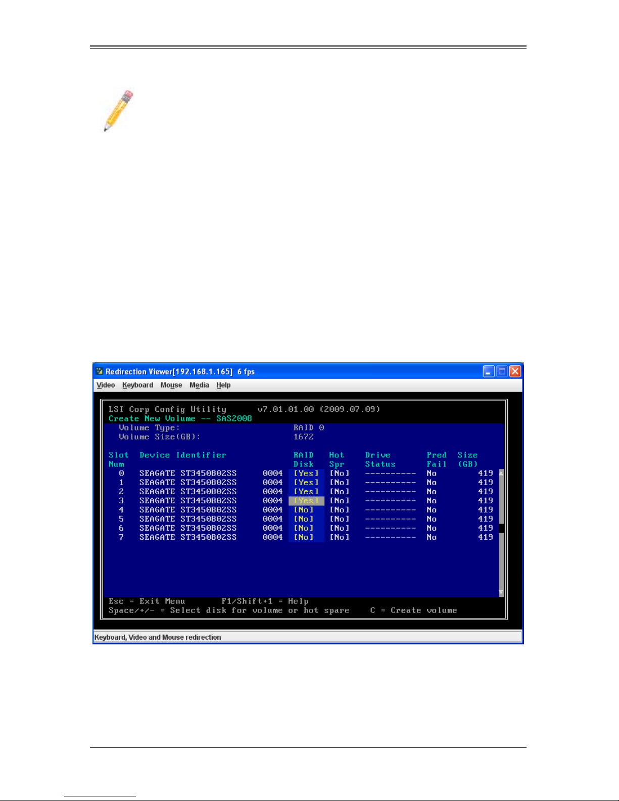
AOC-USAS2-L8i/L8e Add-on Card User’s Manual
NOTE: See the instructions in Section : "Creating Hot Spare Disks" on
page 7-15, if you want to create one or two global hot spares.
7-4 Creating a RAID 0 Volume
Follow these steps to create a RAID 0 volume with the SAS2 BIOS Configuration Utility.
1. On the A
press E
DAPTER LIST screen, use the arrow keys to select a SAS adapter and then
NTER.
The ADAPTER PROPERTIES screen appears (see Figure 7-2).
2. Use the arrow keys to select RAID PROPERTIES, and then press ENTER.
The SELECT NEW VOLUME TYPE screen appears (see Figure 7-3).
3. Select CREATE RAID 0 VOLUME.
The CREATE NEW VOLUME screen appears (Figure 7-7).
Figure 7-9. Create New Volume Screen – RAID 10
4. Move the cursor to the RAID D
this column, indicating that the disk is not already part of the volume being created.
To add the disk to the new volume, change the N
5. Move the cursor to another line and press the space bar to add another disk to the
volume.
ISK column and select a line that has a No entry in
O to Yes by pressing the space bar.
7-10
Page 73
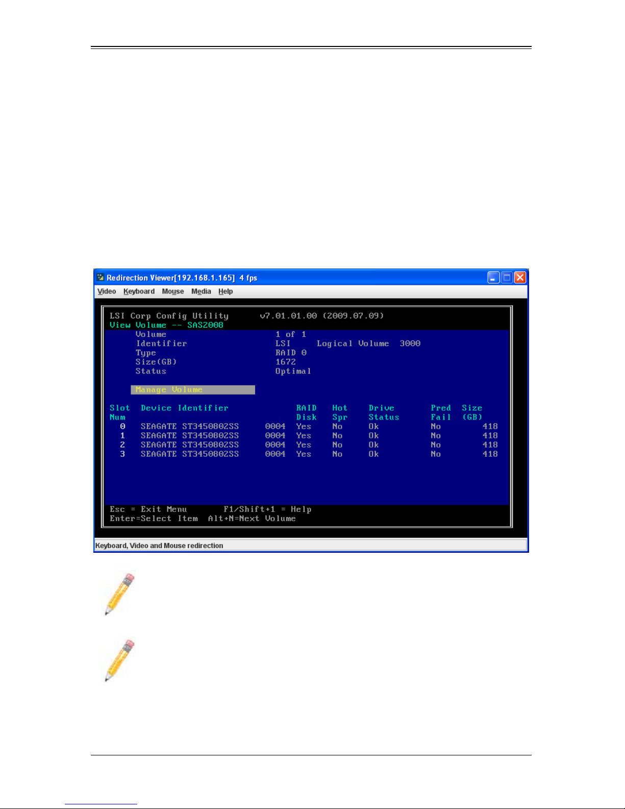
6. Press C to create the volume.
A menu screen appears (see Figure 7-5).
Chapter 7: SAS2 BIOS Configuration Utility
7. From the menu options, select S
AVE CHANGES then exit this menu.
A Processing message appears briefly, and then the SAS2 BIOS Configuration
Utility returns to the A
DAPTER PROPERTIES screen. Initialization of the new volume
continues in the background.
8. From the A
DAPTER PROPERTIES screen, select VIEW EXISTING VOLUME.
The VIEW VOLUME screen appears (Figure 7-8). Use this screen to view your volume
details and review it for correctness.
Figure 7-10. View Volume Screen – RAID 10
NOTE: To create a second RAID 0 volume, repeat the instructions above.
NOTE: Unlike the RAID 1 and RAID 1E/10 volumes, you cannot create a hot
spare for a RAID 0 volume.
7-11
Page 74

AOC-USAS2-L8i/L8e Add-on Card User’s Manual
7-5 Expanding an Integrated Mirroring Volume with
OCE
You can use the online capacity expansion (OCE) feature to expand the capacity of a
two-disk Integrated Mirroring (RAID1) volume by replacing the original disks with two
larger disk drives while the volume remains online. This process maintains data integrity
at all times, even if one of the disks fails during the replacement process. The new disks
must be at least 50 GB larger than the disks they are replacing, and they must use the
same protocol (SAS or SATA) as the disks they are replacing.
Follow these steps to expand an existing RAID1 volume with OCE:
1. Physically replace one of the two volume disk drives with a drive that is at least 50
GB larger.
If necessary , you can identify the disks in the volume by following the instructions in
Locating Disk Drives in a Volume.
2. Wait until synchronization is complete on the new disk and the volume returns to the
optimal state, as indicated in the A
the SAS2 BIOS Configuration Utility.
DAPTER PROPERTIES screen (see Figure 7-2) of
3. Physically replace the other volume disk drive with a drive that is at least 50 GB
larger.
4. Again, wait until synchronization is complete on the new disk and the volume
returns to the optimal state.
5. In the A
keys to select the SAS adapter with the RAID1 volume and then press E
The ADAPTER PROPERTIES screen appears.
DAPTER LIST screen of the SAS2 BIOS Configuration Utility, use the arrow
NTER.
7-12
Page 75
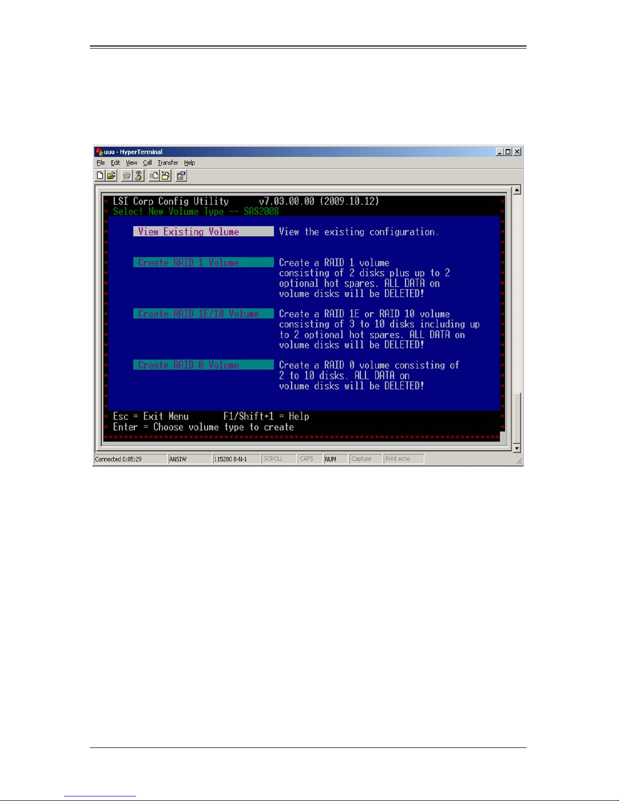
Chapter 7: SAS2 BIOS Configuration Utility
6. Use the arrow keys to select RAID PROPERTIES, and then press ENTER.
The SELECT NEW VOLUME TYPE screen appears (Figure 7-11).
Figure 7-11. Select New Volume Type Screen
7. Select V
IEW EXISTING VOLUME.
The VIEW VOLUME screen appears (Figure 7-4). If necessary , press Alt + N to swi tch
to the RAID1 volume with the new, larger disk drives.
7-13
Page 76
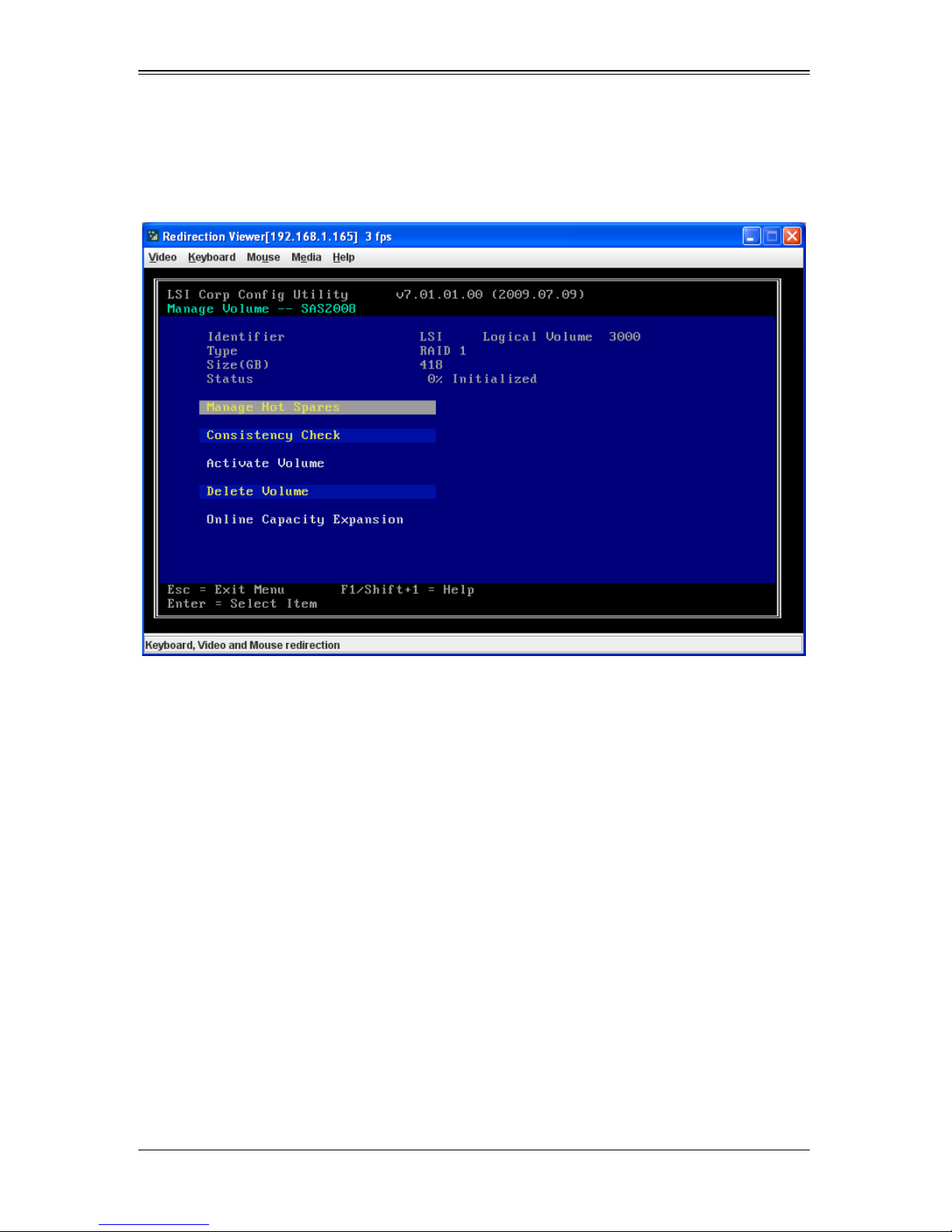
AOC-USAS2-L8i/L8e Add-on Card User’s Manual
8. Select MANAGE VOLUME.
The MANAGE VOLUME screen appears (Figure 7-12).
Figure 7-12. Manage Volume Screen
9. Select O
NLINE CAPACITY EXPANSION.
A menu screen appears with a warning message and with options to start the
expansion process or quit.
10. Press Y to start the expansion.
The RAID P
ROPERTIES screen appears when the expansion process is complete.
This typically occurs in a very short amount of time.
1 1. Run a commercial tool specific to the operating system to move or increase the size
of the partition on the newly-expanded RAID1 volume.
7-14
Page 77

Chapter 7: SAS2 BIOS Configuration Utility
7-6 Hot Sp are Disks
You can create one or two global hot spare disks to protect the data on mirrored
volumes on a SAS2 controller. You can also delete hot spare disks.
Creating Hot Spare Disks
Follow these steps to add global hot spare disks to an existing volume. The steps begin
with the A
1. In the ADAPTER LIST screen, use the arrow keys to select the SAS adapter with the
2. Use the arrow keys to select RAID PROPERTIES, and then press ENTER.
3. Select VIEW EXISTING VOLUME.
DAPTER LIST screen that appears when the configuration utility starts:
volume that needs hot spare disks and then press E
The ADAPTER PROPERTIES screen appears (see Figure 7-2).
The SELECT NEW VOLUME TYPE screen appears (see Figure 7-3).
The VIEW VOLUME screen appears (see Figure 7-6) . If necessary, press Alt + N to
switch to another volume on this adapter.
NTER.
4. Select M
The MANAGE VOLUME screen appears (see Figure 7-12).
ANAGE VOLUME.
7-15
Page 78
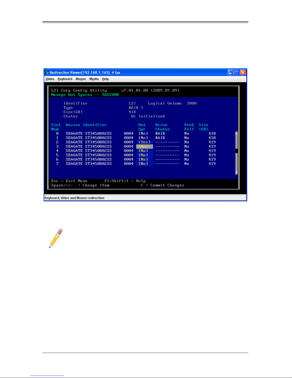
AOC-USAS2-L8i/L8e Add-on Card User’s Manual
5. Select MANAGE HOT SPARES, which is the first option.
The MANAGE HOT SPARES screen appears (Figure 7-13).
Figure 7-13. Manage Hot Spares Screen
6. Identify a disk that is not part of a RAID volume (such as the value in the D
S
TATUS column is not RAID) and that is not already identified as a hot spare disk.
RIVE
NOTE: A global hot spare disk must have 512-byte blocks and nonremovable
media. The disk type must be either SATA with extended command set support
or SAS with SMART support.
7. Move the highlight to the H
OT SPR (HOT SPARE) field for this disk and press the
space bar.
The Hot Spare status changes to Yes.
8. (Optional) Repeat the preceding step to select a second global hot spare disk
9. Press C to create the hot spare disk.
A menu screen appears. An error message appears if the selected disk is not at
least as large as the smallest disk used in the existing volume(s). An error message
also appears if you try to add a SATA disk as a hot spare for volumes that use SAS
disks, or vice versa.
10. Select S
AVE CHANGES then exit this menu to create the hot spare disk(s).
7-16
Page 79

Chapter 7: SAS2 BIOS Configuration Utility
The SAS2 BIOS Configuration Utility pauses while it configures the global hot
spares.
Deleting Hot Spare Disks
Follow these steps to delete a global hot spare disk:
1. Access the Manage Hot Spares screen by following step 1 through step 5 of
"Creating Hot Spare Disks".
2. Select the disk that you no longer wish to use as a hot spare, and press C.
3. Select S
The configuration utility pauses while it removes the global hot spare.
AVE CHANGES then exit this menu to commit the changes.
7-7 Other Configuration Tasks
This section explains how to perform other configuration and maintenance tasks for
mirrored volumes.
Viewing Volume Properties
Follow these steps to view the RAID properties of the mirrored volume(s):
1. In the SAS2 BIOS Configuration Utility, select an SAS2 adapter from the ADAPTER
L
IST screen (see Figure 7-1).
The ADAPTER PROPERTIES screen appears (see Figure 7-2).
2. Select RAID PROPERTIES.
The SELECT NEW VOLUME TYPE screen appears (see Figure 7-3).
3. Select VIEW EXISTING VOLUME.
The VIEW VOLUME screen (see Figure 7-6) appears, showing information about the
volume and each disk in it. The screen includes hot spare information, if you have
created global hot spare disks.
NOTE: If you create one volume using SAS disks, another volume using SATA
disks, and global hot spare disks, the hot spare disks only appear when you
view the mirrored volume that uses the same type of disks as the hot spare
disks.
4. If the currently displayed volume is not the one you want, press Alt+N to view
another volume on the adapter.
Changing Properties
To change volume and device properties, use the Advanced Adapter Properties to
change device and timing properties for your volume and its drives.
7-17
Page 80
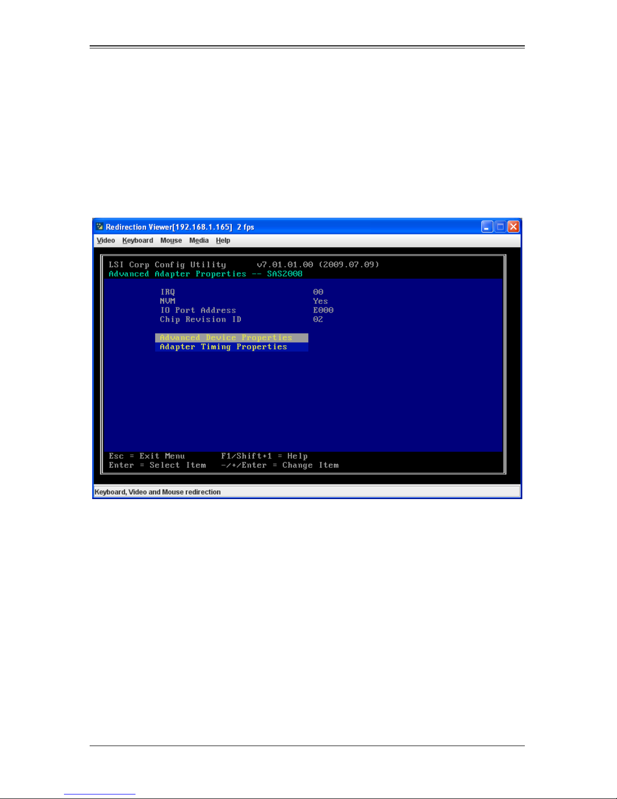
AOC-USAS2-L8i/L8e Add-on Card User’s Manual
Follow these steps to change your device and timing properties:
1. In the SAS2 BIOS Configuration Utility, select an SAS2 adapter from the ADAPTER
L
IST screen (see Figure 7-1).
The ADAPTER PROPERTIES screen appears (see Figure 7-2).
2. Select ADVANCED ADAPTER PROPERTIES.
The ADVANCED ADAPTER PROPERTIES screen appears (see Figure 7-14).
Figure 7-14. Advanced Adapter Properties Screen
3. In the A
P
ROPERTIES or ADAPTER TIMING PROPERTIES .
If you select A
DVANCED ADAPTER PROPERTIES screen choose either ADVANCED DEVICE
DVANCED DEVICE PROPERTIES the ADVANCED DEVICE PROPERTIES
screen appears (Figure 7-15), whereas if you select A
the A
DAPTER TIMING PROPERTIES screen appears (Figure 7-16).
DAPTER TIMING PROPERTIES
7-18
Page 81
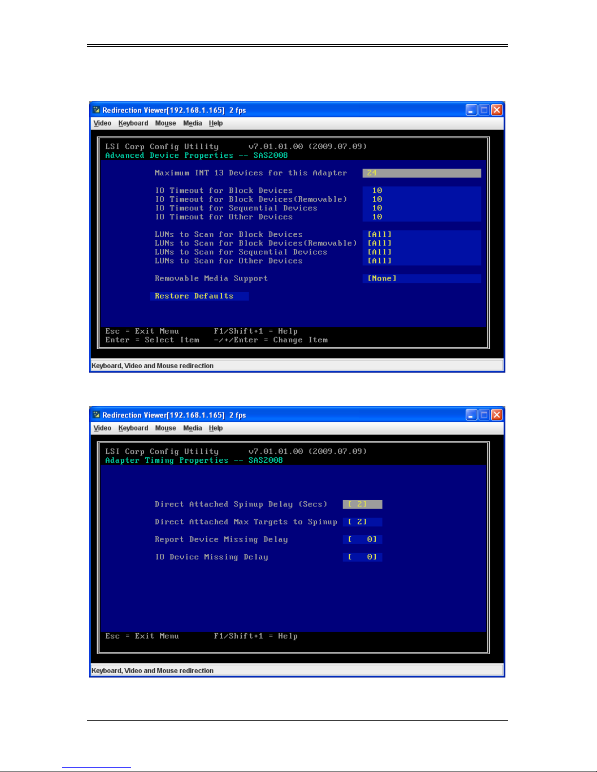
Chapter 7: SAS2 BIOS Configuration Utility
Figure 7-15. Advanced Device Properties Screen
Figure 7-16. Adapter Timing Properties Screen
7-19
Page 82

AOC-USAS2-L8i/L8e Add-on Card User’s Manual
4. In both screens you can change parameters by using the arrow keys to move to a
field and using the +/- keys to change the parameter.
5. When finished, use the E
SC key to exit the menu.
Running a Consistency Check
Use the Consistency Check command to verify that the data is synchronized on the
mirrored disks in the volume.
Follow these steps to run a consistency check on a selected mirrored volume:
1. In the A
adapter.
The A
2. Use the arrow keys to select RAID PROPERTIES, and then press ENTER.
The SELECT NEW VOLUME TYPE screen appears (see Figure 7-3).
3. Select VIEW EXISTING VOLUME.
The VIEW VOLUME screen appears (see Figure 7-8) . If necessary, press Alt + N to
switch to another volume on this adapter.
4. S
ELECT MANAGE VOLUME.
The MANAGE VOLUME screen appears (see Figure 7-12).
DAPTER LIST screen (see Figure 7-1), use the arrow keys to select a SAS
DAPTER PROPERTIES screen appears (see Figure 7-2).
5. Select CONSISTENCY CHECK in the MANAGE VOLUME screen.
A menu screen appears.
6. Press Y to start the consistency check.
The consistency check runs a read-read-compare algorithm in the background. If it
encounters any data miscompares, it stores the information in a bad block table.
Activating a Volume
A volume can become inactive if, for example, you remove it from one controller or
computer and install it on a different one. The Activate Volume option allows you to
reactivate an inactive volume. This option is available only when the selected volume is
currently inactive.
Follow these steps to activate a selected volume:
1. In the A
adapter and press E
The ADAPTER PROPERTIES screen appears (seeFigure 7-2 ).
2. Select RAID PROPERTIES, and then press ENTER.
The SELECT NEW VOLUME TYPE screen appears (see Figure 7-3).
DAPTER LIST screen (see Figure 7-1), use the arrow keys to select a SAS
NTER.
3. Select VIEW EXISTING VOLUME.
7-20
Page 83
Chapter 7: SAS2 BIOS Configuration Utility
The VIEW VOLUME screen appears (see Figure 7-6). If necessary, press Alt + N to
switch to another volume on this adapter.
4. Select M
ANAGE VOLUME.
The MANAGE VOLUME screen appears (see Figure 7-12).
5. Select ACTIVATE VOLUME in the MANAGE VOLUME screen.
A menu screen appears.
6. Press Y to activate the volume.
The volume becomes active after a pause.
Deleting an Volume
WARNING: Before you delete an volume, be sure to back up all data on the
volume that you want to keep.
Follow these steps to delete a selected volume (volume):
1. In the ADAPTER LIST screen (see Figure 7-1), use the arrow keys to select a SAS
adapter.
The A
DAPTER PROPERTIES screen appears (see Figure 7-2).
2. Use the arrow keys to select RAID PROPERTIES, and then press ENTER.
The SELECT NEW VOLUME TYPE screen appears (see Figure 7-3).
3. Select VIEW EXISTING VOLUME.
The VIEW VOLUME screen appears (see Figure 7-6). If necessary, press Alt + N to
switch to another volume on this adapter.
4. Select M
ANAGE VOLUME.
The MANAGE VOLUME screen appears (see Figure 7-12).
5. Select D
ELETE VOLUME.
A menu screen appears.
6. Press Y to delete the volume, or press N to cancel the deletion process.
After a pause, the utility deletes the volume. If there is another remaining volume
and one or two hot spare disks, the BIOS checks the hot spare disks to determine if
they are compatible with the remaining volume. If they are not compatible (too small
or wrong disk type), the BIOS deletes them also.
7-21
Page 84
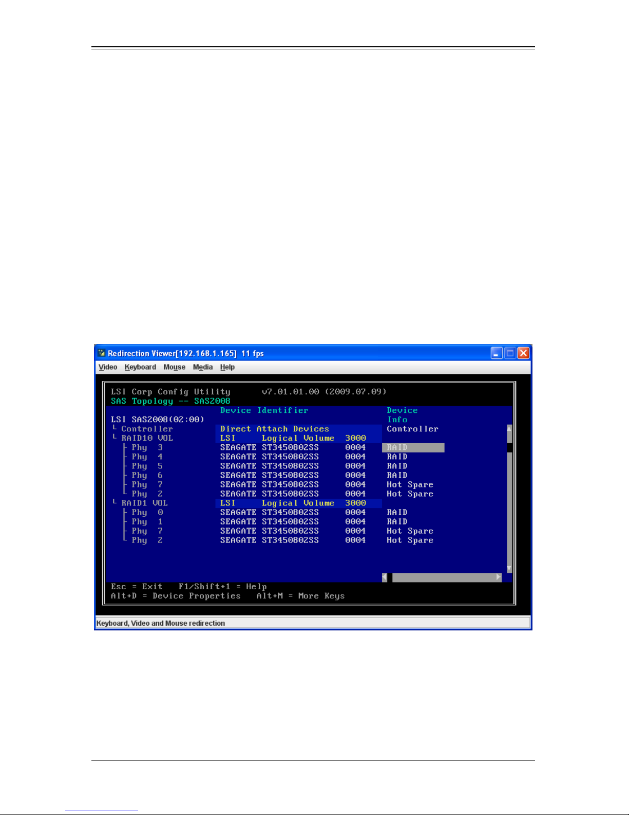
AOC-USAS2-L8i/L8e Add-on Card User’s Manual
Locating Disk Drives in a Volume
You can use the SAS2 BIOS Configuration Utility to locate and identify a specific
physical disk drive in a disk enclosure by flashing the drive’s LED. You can also flash the
LEDs of all the disk drives in a RAID volume, if they are in a disk enclosure.
When you add a disk drive to a new mirrored volume, the LED on the disk drive starts
flashing. The LED stops flashing when you finish creating the volume.
You can locate individual disk drives from the SAS Topology screen by flashing their
LEDs. To do this, follow these steps:
1. Select the desired SAS2 controller on the A
press E
The A
NTER.
DAPTER PROPERTIES screen appears (see Figure 7-2).
2. Highlight SAS TOPOLOGY and press ENTER.
The SAS TOPOLOGY screen appears (Figure 7-17).
Figure 7-17. SAS Topology Screen
DAPTER LIST screen (see Figure 7-1) and
3. Select the disk in the D
The LED on the disk flashes until you press a key to stop it.
4. To identify all the disk drives in a volume, select the volume in the left column of the
SAS T
OPOLOGY screen and press ENTER.
The LEDs flash on all disk drives in the volume until you press a key to stop them.
EVICE IDENTIFIER column and press ENTER.
7-22
Page 85

Chapter 7: SAS2 BIOS Configuration Utility
NOTE: The LEDs on the disk drives will flash as described above if the
firmware is correctly configured and the drives are in a disk enclosure.
Selecting a Boot Disk
You can select a boot disk in the SAS TOPOLOGY screenscreen. The next time you boot
the computer, the firmware moves this disk to scan ID 0, making it the new boot disk.
This makes it easier to set BIOS boot device options and to keep the boot device
constant during device additions and removals. You can also select an alternative boot
device. If the BIOS cannot find the preferred boot device when it loads, it will attempt to
boot from the alternate device.
Follow these steps to select a boot disk:
1. In the SAS2 BIOS Configuration Utility, select an adapter from the A
DAPTER LIST
screen (see Figure 7-1).
2. If a device is currently configured as the boot device, the B
OOT ORDER column on
the screen lists the number 0.
If a device is currently configured as the alternate boot device, the B
OOT ORDER
column shows a succeding number.
3. To change the boot order, use the +/- key to alter the boot order between the
controllers listed.
The Boot order moves to the disk you choose.
4. To change the boot list, use the I
NS/DEL keys instead.
Changing Boot Support
You can change the boot support from the BIOS and the OS from the ADAPTER
P
ROPERTIES screen.
Follow these steps to select the boot support for the volume.
1. Select the desired SAS2 controller on the A
press E
NTER.
DAPTER LIST screen (see Figure 7-1) and
The A
DAPTER PROPERTIES screen appears (see Figure 7-2).
2. In the ADAPTER PROPERTIES screen, scroll to the Boot Support row and use the +/keys to change the entry in the field. You may choose to enable either BIOS, OS or
E
NABLED BIOS & OS for your boot support.
7-23
Page 86

AOC-USAS2-L8i/L8e Add-on Card User’s Manual
Notes
7-24
Page 87

Chapter 8
MegaRAID Overview and Installation
This chapter explains provides and overview of MegaRAID Storage Manager software,
and instructions on how to install (or reinstall) the software on your workstation or server
for the supported operating systems, which include: Microsoft Windows, Red Hat Linux,
and SUSE Linux. 5.3.1 Installing MegaRAID Storage Manager Software on Microsoft
Windows.
8-1 Overview
MegaRAID Storage Manager software enables you to configure, monitor, and maintain
storage configurations created under Embedded MegaRAID Software. The MegaRAID
Storage Manager graphical user interface (GUI) makes it easy for you to create and
manage storage configurations.
NOTE: MegaRAID Storage Manager software can be used to manage a wide
range of MegaRAID controllers. Some MegaRAID Storage Manager software
features are not applicable for Embedded MegaRAID Software.
Creating Storage Configurations
MegaRAID Storage Manager software enables you to easily configure the controllers,
disk drives, and virtual disks on your workstation or server. The Configuration Wizard
greatly simplifies the process of creating arrays and virtual disks.
You can use the Configuration Wizard’s Auto Configuration mode to automatically
create the best possible configuration with the available hardware. You can use the
Guided Configuration mode, which asks you a few brief questions about the
configuration, and then creates it for you. Or you can use the Manual Configuration
mode, which gives you complete control over all aspects of the storage configuration.
Monitoring Storage Devices
MegaRAID Storage Manager software displays the status of virtual disks, physical disks,
and other storage devices on the workstation or server that you are monitoring. System
errors and events are recorded in an event log file and are displayed on the screen.
Special device icons appear on the screen to notify you of disk failures and other events
that require immediate attention.
Maintaining Storage Configurations
You can use MegaRAID Storage Manager software to perform system maintenance
tasks such as running consistency checks on arrays that support redundancy.
8-1
Page 88

AOC-USAS2-L8i/L8e Add-on Card User’s Manual
8-2 Hardware and Software Requirements
The hardware requirements for MegaRAID Storage Manager software are as follows:
• PC-compatible computer with an IA-32 (32-bit) Intel Architecture processor or an
EM64T (64-bit) processor and at least 128 Mbytes of system memory (256 Mbytes
recommended)
• Hard disk drive with at least 50 Mbytes available free space
The supported operating systems for the MegaRAID Storage Manager software are as
follows:
• Microsoft Windows 2000, Microsoft Windows Server 2003, Microsoft Windows XP,
Microsoft Vista and Microsoft Windows Server 2008.
• Red Hat Linux 3.0 or 4.0
• SUSE SLES 9, with latest updates and service packs
Refer to your server documentation and to the operating system documentation for
more information on hardware and operating system requirements.
8-3 Installing for Windows
Follow these steps if you need to install MegaRAID Storage Manager software on a
system running Microsoft Windows 2000, Microsoft Windows Server 2003, or Microsoft
Windows XP:
1. Insert the MegaRAID Storage Manager software installation CD in the CD-ROM
drive.
If necessary , find and double-click the setup.exe file to start the installation program.
2. When the W
If MegaRAID Storage Manager software is already installed on this system, the
P
ROGRAM MAINTENANCE screen appears. Read the screen text and select MODIFY,
R
EPAIR, or REMOVE.
3. When the next screen appears, read and accept the user license, and click NEXT.
USTOMER INFORMATION screen appears.
The C
4. Enter your user name and organization name, and in the bottom part of the screen,
select an installation option:
• If you select A
sion of MegaRAID Storage Manager software to view or change storage configurations.
• If you select O
cuts and associates icon availability to only the user with this screen’s user
name.
ELCOME screen appears, click NEXT.
LL USERS, any user with administrative privileges can use this ver-
NLY FOR CURRENT USER, the MegaRAID Storage Manager short-
Click N
EXT to continue.
8-2
Page 89

Chapter 8: MegaRAID Overview and Installation
5. On the next screen, accept the default destination folder, or click CHANGE to select a
different destination folder.
Click N
EXT to continue.
The SETUP TYPE screen appears.
6. Select one of the Setup options. The options are fully explained in the screen text.
• Select C
OMPLETE if you are installing MegaRAID Storage Manager software on
a server.
• Select C
LIENT if you are installing MegaRAID Storage Manager software on a
PC that is used to view and configure servers over a network.
• Select S
ERVER to install only those components required for remote server man-
agement.
• Select S
TANDALONE if you are using MegaRAID Storage Manager software to
create and manage storage configurations on a standalone workstation.
Click N
EXT to proceed.
7. On the next screen, click INSTALL to install the program.
8. Click FINISH when the final CONFIGURATION WIZARD screen appears.
If you select CLIENT installation for a PC used to monitor servers, and if there are no
available servers with a registered framework on the local subnet (that is, servers with a
complete installation of MegaRAID Storage Manager software), you cannot connect to a
remote server unless you first edit the startupui.bat file. Specifically, you must add the IP
address of the remote server to the end of the startupui.bat file.
For example, to connect to a remote framework on server 192.168.0.10, add the IP
address to the end of startupui.bat as shown in this example:
start JRE\bin\javaw -classpath .;GUI.jar
GUI.VivaldiStartupDialog ajsgyqkj=71244 192.168.0.10
Be sure to include a space in front of the IP address, as shown in the above example.
8-4 Installing for Linux
Follow these steps if you need to install MegaRAID Storage Manager software on a
system running Red Hat Linux or SUSE Linux:
1. Copy the MSM_linux_installer...tar.gz file to a temporary folder.
2. Untar the MSM_linux_installer...tar.gz file using the following command:
tar -zxvf MSM_linux_installer...tar.gz
A new disk directory is created.
3. Go to the new disk directory, and in that directory find and read the readme.txt file.
4. To start the installation, enter the following command :
./install.sh
8-3
Page 90

AOC-USAS2-L8i/L8e Add-on Card User’s Manual
If you select CLIENT installation for a PC used to monitor servers, and if there are no
available servers with a registered framework on the local subnet (that is, servers with a
complete installation of MegaRAID Storage Manager software), you cannot connect to a
remote server unless you first edit the startupui.sh file. Specifically, you must add the IP
address of the remote server to the end of the startupui.sh file.
For example, to connect to a remote framework on server 192.168.0.10, add the IP
address to startupui.sh as shown in this example:
start JRE\bin\javaw -classpath .;GUI.jar
GUI.VivaldiStartupDialog ajsgyqkj=71244 192.168.0.10
Be sure to include a space in front of the IP address, as shown in the above example.
Linux Error Messages
One or more of the following messages may appear while you are installing MegaRAID
Storage Manager software on a Linux system:
• More than one copy of MegaRAID Storage Manager software has
been installed.
This message indicates that the user has installed more than one copy of
MegaRAID Storage Manager software. (This can be done by using the rpm-force
command to install the rpm file directly, which is not recommended, instead of using
the install.sh file.) In such cases, the user must uninstall all the rpm files manually
before installing MegaRAID Storage Manager software with the procedure listed
previously.
• The version is already installed.
This message indicates that the version of MegaRAID Storage Manager software
you are trying to install is already installed on the system.
• The installed version is newer.
This message indicates that a version of MegaRAID Storage Manager software is
already installed on the system, and it is a newer version than the version you are
trying to install.
• Exiting installation.
This is the message that appears when the installation is complete.
• RPM installation failed.
This message indicates that the installation failed for some reason. Additional
message text explains the cause of the failure.
8-4
Page 91

Chapter 9
MegaRAID Window and Menus
The MegaRAID Storage Manager software is a configuration and monitoring utility used
with the Embedded MegaRAID Software. This chapter provides instruction on its use
and features.
9-1 Starting MegaRAID Storage Manager Software
Follow these steps to start MegaRAID Storage Manager software and view the main
window:
1. Start the program using the method required for your operating system
environment:
• To start MegaRAID Storage Manager software on a Microsoft Windows system,
select S
double-click the M
NOTE: If a warning appears stating that Windows Firewall has blocked some
features of the program, click U
software to start.
TART J PROGRAMS J MEGARAID STORAGE MANAGER J STARTUPUI, or
EGARAID STORAGE MANAGER shortcut on the desktop.
NBLOCK to allow MegaRAID Storage Manager
This is because Windows Firewall sometimes blocks the operation of programs
that use Java.
• To start MegaRAID Storage Manager software on a Red Hat Linux system,
select A
S
TARTUPUI.
• To start MegaRAID Storage Manager software on a SUSE SLES 9 system,
select S
When the program starts, the SELECT SERVER window appears.
If the circle in the server icon is yellow instead of green, it means that the server is
running in a degraded state–for example, because a disk drive used in a virtual disk
has failed. If the circle is red, the storage configuration in the server has failed.
NOTE: To access servers on a different subnet, type in the box at the bottom of
the screen the IP address of a server in the desired subnet where MegaRAID
Storage Manager software is running, and click U
Connect to remote Framework box, you can also access a standalone
installation of MegaRAID Storage Manager software, if it has a network
connection.
2. Double-click the icon of the server that you want to access.
PPLICATIONS J SYSTEM TOOLS J MEGARAID STORAGE MANAGER J
TART J SYSTEM J MORE PROGRAMS J MEGARAID STORAGE MANAGER.
PDATE. If you check the
The S
ERVER LOGIN window appears.
3. Select an access mode from the drop-down menu.
9-1
Page 92
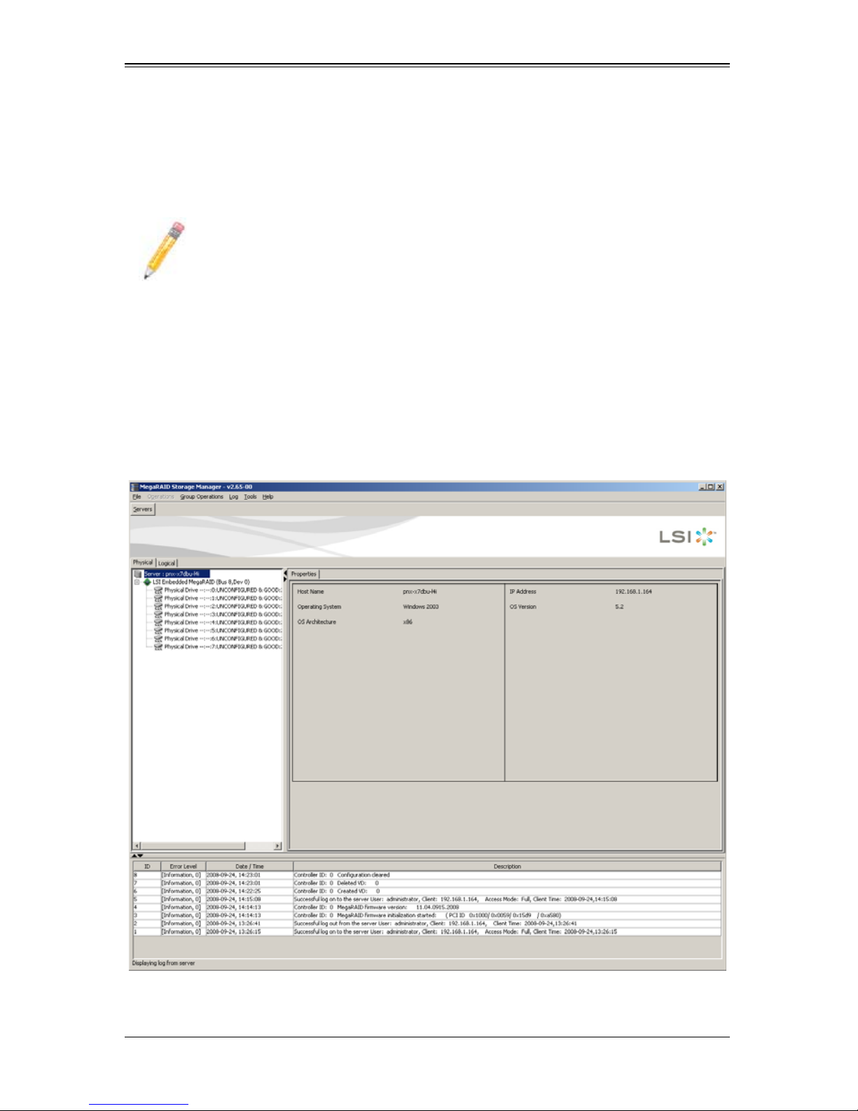
AOC-USAS2-L8i/L8e Add-on Card User’s Manual
• Select FULL ACCESS if you need to both view the current configuration and
change the configuration.
• Select V
IEW ONLY if you need to only view and monitor the configuration.
4. Enter your user name and password, and click LOGIN.
NOTE: If the computer is net worked, this is the login to the computer itself, not
the network login.
You must enter the root/administrator user name and password to use Full Access
mode. If your user name and password are correct for the Login mode you have
chosen, the main M
EGARAID STORAGE MANAGER window appears.
9-2 MegaRAID Storage Manager Window
This section describes the MEGARAID STORAGE MANAGER window (Figure 9-1).
Figure 9-1. Storage Manager Window
The following sections describe the panels and menu options that appear in this window.
9-2
Page 93

Chapter 9: MegaRAID Window and Menus
Physical/Logical View Panel
The left panel of the MEGARAID STORAGE MANAGER window displays either the Physical
view or the Logical view of the system and the devices in it, depending on which tab is
selected.
• The Physical view shows the hierarchy of physical devices in the system. At the top
of the hierarchy is the system itself. One or more controllers are installed in the
system. Each controller has one or more ports. Disk drives and other devices are
attached to the ports.
• The Logical view shows the hierarchy of controllers, virtual disks, and disk groups
that are defined on the system. (Physical drives also appear in the Logical view, so
you can see which physical drives are used by each virtual disk.)
The following icons in the left panel represent the controllers, disk drives, and other
devices:
•System
• Controller
•Port
• Array
• Virtual disk
• Physical drive
A red circle to the right of an icon indicates that the device has failed.
A yellow circle to the right of an icon indicates that a device is running in a degraded
state.
Properties/Operations/Graphical View Panel
The right panel of the MEGARAID STORAGE MANAGER window has either two or three
tabs, depending on what kind of device is selected in the left panel.
• The P
• The O
• The G
ROPERTIES tab displays information about the selected device. For example, if
a controller icon is selected in the left panel, the P
ROPERTIES tab lists information
such as the controller name and the device port count.
PERATIONS tab lists the operations that can be performed on the device that is
selected in the left panel. Some types of devices, such as arrays and ports, do not
have operations associated with them.
RAPHICAL VIEW tab can be selected in the right panel if a physical drive or
virtual disk is selected in the left panel. In graphical view, the device’s storage
capacity is color coded according to the legend shown on the screen. For example,
on a physical drive configured space is blue, available space is white, and reserved
space is red.
9-3
Page 94

AOC-USAS2-L8i/L8e Add-on Card User’s Manual
Event Log Panel
The lower part of the MEGARAID STORAGE MANAGER window displays the system event
log entries. New event log entries appear during the session. Each entry has a
timestamp and date, an error level indicating the severity of the event, and a brief
description of the event.
Menu Bar
This section contains brief descriptions of the main selections from the MEGARAID
S
TORAGE MANAGER menu bar.
File Menu
The FILE menu has an EXIT option for exiting from the MEGARAID STORAGE MANAGER
software. It also has a R
S
TORAGE MANAGER window. (RESCAN is seldom required; the display normally updates
automatically.)
Operations Menu
ESCAN option for updating the display in the MEGARAID
The OPERATIONS menu is available when a controller, physical drive, or logical drive is
selected in the M
include: C
C
ONFIGURATION. These options are also sometimes available if you right-click on an item
in the P
REATE VIRTURAL DRIVE, CONFIGURATION and SCAN FOR FOREIGN
HYSICAL/LOGICAL VIEW panels.
EGARAID STORAGE MANAGER window. Options available in this menu
The CREATE VIRTURAL DRIVE option allows you to create a virtual drive for your
configuration. See Section 9-3: "Creating a New Storage Configuration" on page 9-5 for
more details.
The C
ONFIGURATION option contains a submenu that includes options for Adding, Saving
or Clearing a configuration file of your configuration. See Section 9-6: "Controller
Configuration Files" on page 9-13 for more details.
The S
CAN FOR FOREIGN CONFIGURATION option will scan your system for foreign
configurations you may wish to use.
Group Operations Menu
The GROUP OPERATIONS menu contains the SHOW PROGRESS menu option for displaying
progress on your drive configurations.
Tools Me nu
The TOOLS menu contains the CONFIGURE submenu with the CONFIGURE ALERTS menu
option. See Section 9-8: "Configuring Alerts" on page 9-16 for more details.
Log Menu
The LOG menu includes the following options for the log in the EVENT LOG panel: SAVE
L
OG, SAVE LOG TEST, VIEW SAVED LOG and CLEAR LOG.
9-4
Page 95
Chapter 9: MegaRAID Window and Menus
Help Menu
On the HELP menu you can select HELP J HELP to view the MegaRAID Storage
Manager software online help file. You can select H
ELP J ABOUT to view version
information for the MegaRAID Storage Manager software.
NOTE: When you use the MegaRAID Storage Manager software online help,
you may see a warning message that Internet Explorer has restricted the file
from showing active content. If this warning appears, click on the active content
warning bar and enable the active content.
9-3 Creating a New Storage Configuration
You may use MegaRAID Storage Manager software to also create and modify virtual
drive configurations. The RAID 0, RAID 1 and RAID 10 storage configurations are
supported using this software.
WARNING: It is recommended that you do not use both SAS and SA TA drives in
the same array. Using different drive interfaces in this way could cause
unpredictable behavior, decreased performance, an increased error count, and
decreased MTBF.
NOTE: You cannot create or modify a storage configuration unless you are
logged on with administrator privileges.
To open the MegaRAID Storage Manager Configuration Wizard, select a controller in
the left P
Then select O
HYSICAL/LOGICAL VIEW panel of the MEGARAID STORAGE MANAGER window.
PERATIONS J CREATE VIRTUAL DRIVE.
This brings up the Configuration Wizard’s Create Virtual Drive–Choose Mode
screen (Figure 9-2).
9-5
Page 96
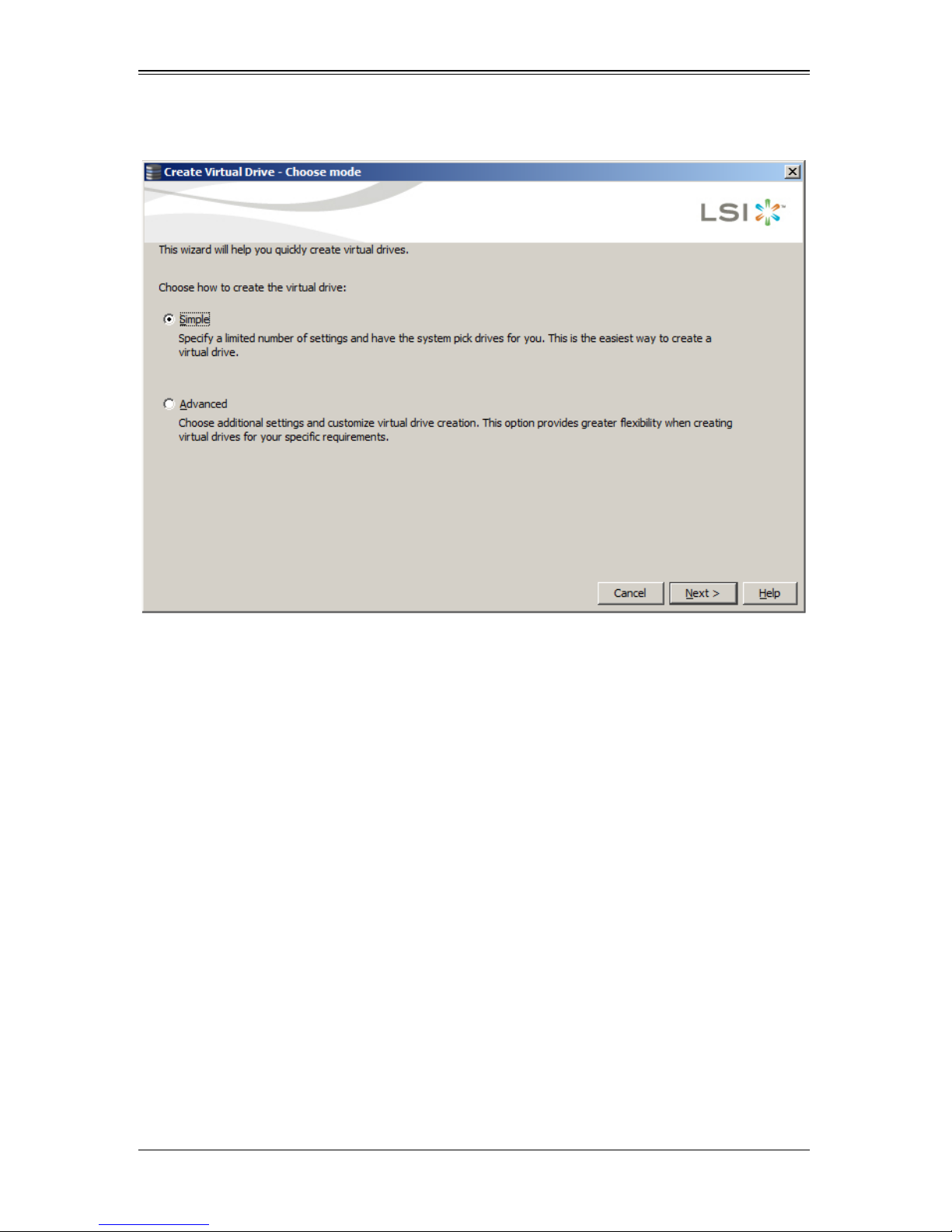
AOC-USAS2-L8i/L8e Add-on Card User’s Manual
Figure 9-2. Create Virtual Drive–Choose Mode Screen
This screen has options for creating a virtual drive using either the Simple method or the
Advanced method. After choosing your method, press the N
EXT button to continue.
9-6
Page 97
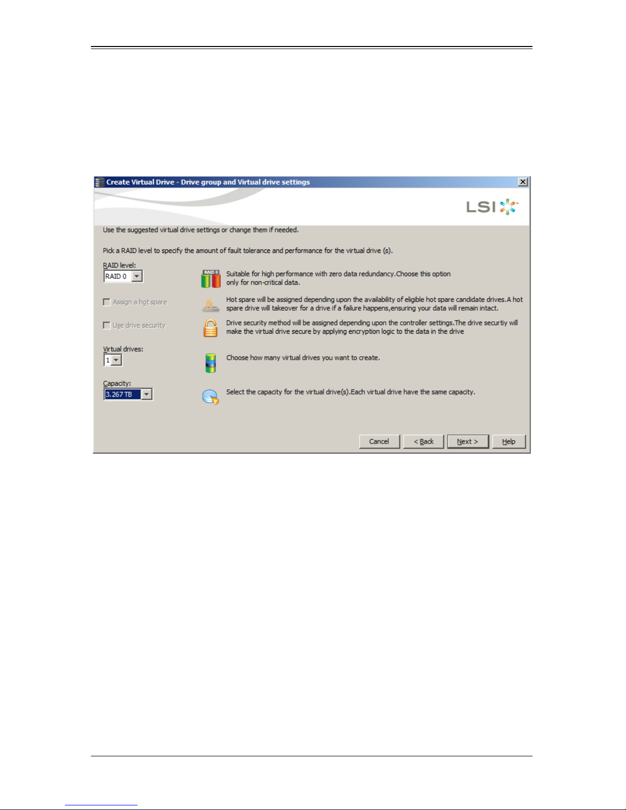
Chapter 9: MegaRAID Window and Menus
Creating a Virtual Drive Using the Simple Method
If you choose the Simple method for creating a virtual drive, then the next screen that
appears is the C
screen (Figure 9-3).
Figure 9-3. Create Virtual Drive–Drive Group and Virtual Drive Settings Screen
REATE VIRTUAL DRIVE–DRIVE GROUP AND VIRTUAL DRIVE SETTINGS
For the rest of the Simple configuration, use the below procedure.
1. In the C
REATE VIRTUAL DRIVE–DRIVE GROUP AND VIRTUAL DRIVE SETTINGS screen
set the following parameters:
• RAID Level: Use this setting to set your RAID level to either RAID level 0, 1 or 10.
• Assign a Hotspare: Check this box in order to specify if you want a hotspare disk
set asside from those available.
• Use Drive Security: Check this box if you wish to assign the drive security method
upon the controller settings.
• Virtual Drives: Use this setting to set the number of virtual drives you wish to create
for your configuration.
• Capacity: Use this setting to set the capacity for your virtual drive(s). Each virtual
drive will have the same capacity.
When you have set your parameters, press the N
EXT button to continue.
9-7
Page 98
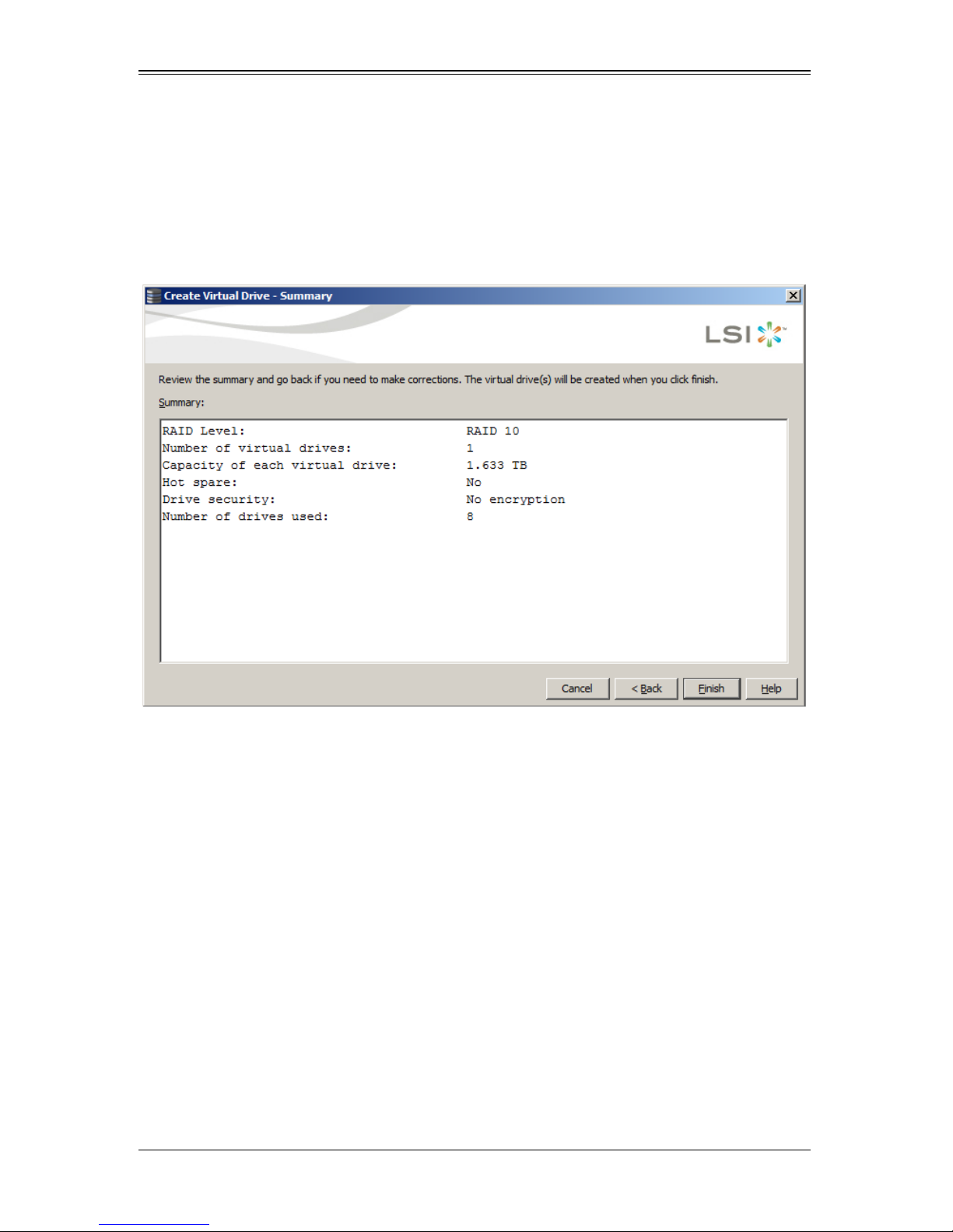
AOC-USAS2-L8i/L8e Add-on Card User’s Manual
2. In the SUMMARY screen (Figure 9-4) that appears review your settings, and when
satisfied, press the F
If you wish to change your settings, press the BACK button to go to the previous
C
REATE VIRTUAL DRIVE–DRIVE GROUP AND VIRTUAL DRIVE SETTINGS screen and
change them.
Figure 9-4. Simple Configuration Summary Screen
INISH button.
9-8
Page 99
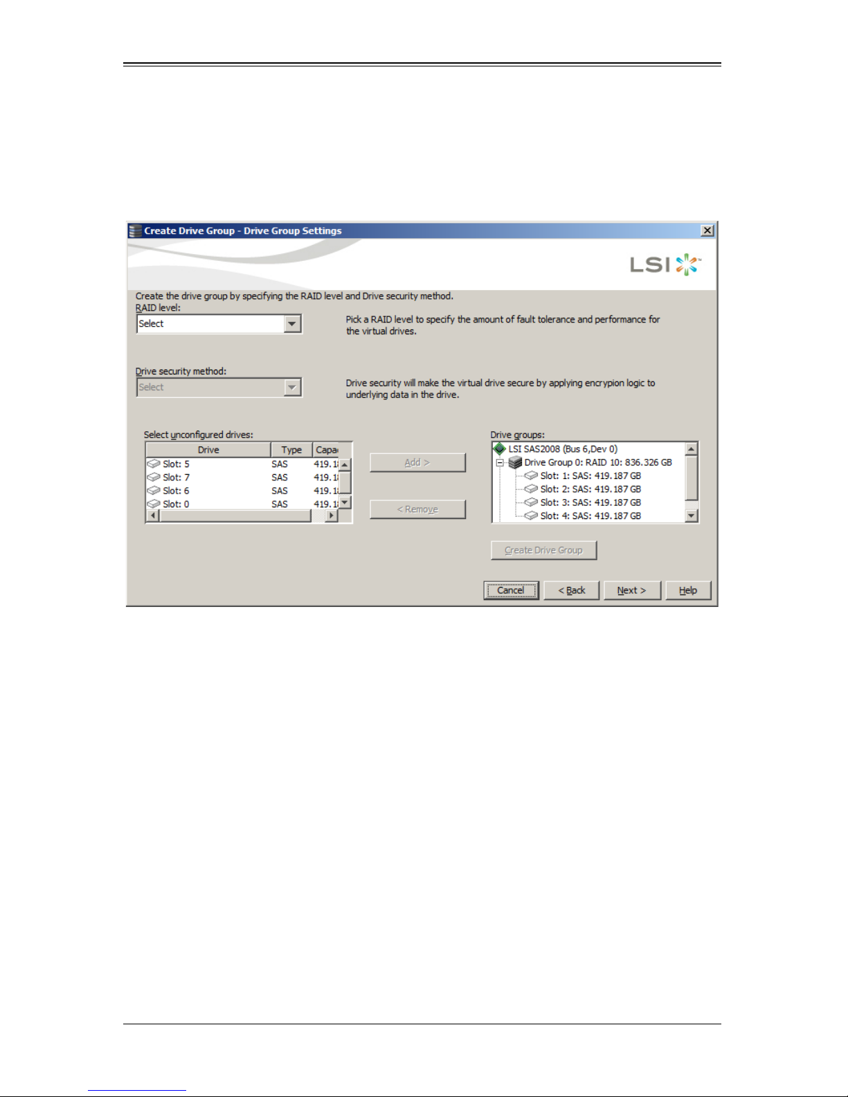
Chapter 9: MegaRAID Window and Menus
Creating a Virtual Drive Using the Advanced Method
If you choose the Advanced method for creating a virtual drive, then the next screen that
appears is the C
Figure 9-5. Create Drive Group–Drive Group Settings Screen
REATE DRIVE GROUP–DRIVE GROUP SETTINGS screen (Figure 9-5)
For the rest of the Advanced configuration, use the below procedure.
1. In the C
REATE DRIVE GROUP–DRIVE GROUP SETTINGS screen set the following
parameters:
• RAID Level: Use this setting to set your RAID level to either RAID level 0, 1 or 10.
• Drive Security Method: Select the drive security method you wish to use in your
configuration.
• Select Unconfigured Drives/Drive Groups Panes: Select the unconfigured drives
you wish to use for your virtual drive con figuration, and use the A
the unconfigured drive(s) to D
button to remove them from the D
drives, press the C
REATE DRIVE GROUP button to create your drive group.
RIVE GROUPS pane. You can also use the REMOVE
RIVE GROUPS pane. When finished selecting your
DD button to move
When you have set your all your parameters in this screen, press the NEXT button to
continue.
9-9
Page 100
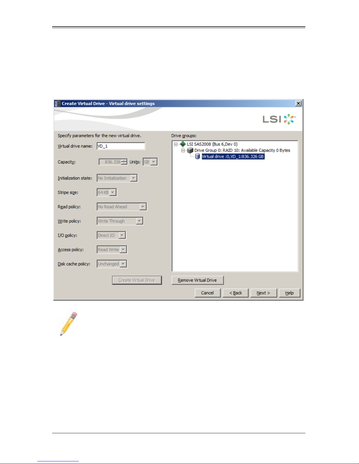
AOC-USAS2-L8i/L8e Add-on Card User’s Manual
2. In the CREATE VIRTUAL DRIVE–VIRTUAL DRIVE SETTINGS screen that appears
(Figure 9-6), set parameters for all active controls.
When finished, press the C
REATE VIRTUAL DRIVE button and then press the NEXT
button to continue.
Figure 9-6. Create Virtual Drive–Virtual Drive Settings Screen
NOTE: Not all controls will be active in this screen.
9-10
 Loading...