

Page 1
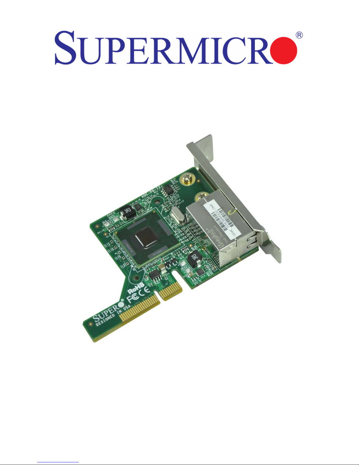
AOC-PG-i2+ Add-on Card
User’s Guide
Revison 1.0a
Page 2

AOC-PG-i2+ Add-on Card User’s Guide
The information in this User’s Manual has been carefully reviewed and i s believed to be accurate. The
vendor assumes no responsibility for any inaccuracies that may be contained in this document, makes no
commitment to update or to keep current the information in this manual, or to not ify any person or
organization of the u pdates. Plea se Note: For the most up-to-date version of this manual, please see
our web site at www.supermicro.com.
Super Micro Computer, Inc. (“Super micro”) reserves the right to make changes to the product described
in this manual at any time and without notice. This product, including software, if any, and documentation
may not, in whole or in part, be copied, photocop ied, re produced, translated or redu ced t o any medi um or
machine without prior written consent.
IN NO EVENT WILL SUPERMICRO BE LIABLE FOR DIRECT, INDIRECT, SPECIAL, INCIDENTAL,
SPECULATIVE OR CONSEQUENTIAL DAMAGES ARISING FROM THE USE OR INABILITY TO USE
THIS PRODUCT OR DOCUMENTATION, EVEN IF ADVISED OF THE POSSIBILITY OF SUCH
DAMAGES. IN PARTICULAR, SUPERMICRO SHALL NOT HAVE LIABILITY FOR ANY HARDWARE,
SOFTWARE, OR DATA STORED OR USED WITH THE PRODUCT, INCLUDING THE COSTS OF
REPAIRING, REPLACING, INTEGRATING, INSTALLING OR RECOVERING SUCH HARDWARE,
SOFTWARE, OR DATA.
Any disputes arising between manufacturer and cu stomer shall be governed by the laws of Santa Clara
County in the State of California, USA. The State of California, Co unty of Santa Clara shall be the
exclusive venue for the resolution of any such disputes. Super Micro's total liabilit y for all claims will not
exceed the price paid for the hardware product.
FCC State ment: This equipment has been tested and found to comply with the limits for a Class A digital
device pursuant to Part 15 of the FCC Rules. These limits are designed to provide reasonable protection
against harmful interference when the equipment is operated in a commercial environment. This
equipment generates, uses, and can radiate radio frequency energy and, if not installed and used in
accordance with the manufacturer’s instruction manual, may cause harmful interference with radio
communications. Operation of this equipment in a residential area is likely to cause harmful interference,
in which case you will be required to correct the interference at your own expense.
California Best Management Practices Regulations for Perchlorate Materials: This Perchlorate warning
applies only to products containing CR (Manganese Dioxide) Lithium coin cells. Perchlorate
Material-special handling may apply. See www.dtsc.ca.gov/hazardouswaste/perchlorate for further
details.
WARNING: HANDLING OF LEAD SOLDER MATERIALS USED IN THIS
PRODUCT MAY EXPOSE YOU TO LEAD, A CHEMICAL KNOWN TO THE
STATE OF CALIFORNIA TO CAUSE BIRTH DEFECTS AND OTHER
REPRODUCTIVE HARM.
Manual Revison 1.0a
Release Date: February 4, 2010
Unless you request and receive written permission from Super Micro Computer, Inc., you may not copy
any part of this document.
Information in this document is subject to change without notice. Other products and companies referred
to herein are trademarks or registered trademarks of their respective companies or mark holders.
Copyright © 2010 by Super Micro Computer, Inc.
All rights reserv ed .
Printed in the United States of America
ii
Page 3

Table of Contents
Chapter 1 Safety Guidelines..........................................................1-1
1-1 ESD Safety Guidelines.....................................................................1-1
1-2 General Safety Guidelines...............................................................1-1
1-3 An Important Note to Users.............................................................1-1
Chapter 2 Card Components.........................................................2-1
2-1 Front Components ............................................................................2-1
2-2 Front Connectors, Jumpers and LEDs..........................................2-2
LAN Ports................................................................................................2-2
LAN Port LEDs........................................................................................2-2
2-3 Riser Card..........................................................................................2-3
2-4 System Installation............................................................................2-4
Chapter 3 Installing the Drivers...................................................3-1
3-1 Installing the Drivers in Microsoft Windows..................................3-1
3-2 Intel PROSet for Windows Device Manager.................................3-1
Installing Intel PROSet for Windows Device Manager..................... ... ... .3-2
Tips for PROSet Users.................................................................. ... ... .3-2
Removing Intel PROSet for Windows Device Manager..........................3-2
Receive Side Scaling............................................................... ... ............3-2
RSS Configuration ...............................................................................3-2
Teaming................................................................................................3-2
3-3 Installing the Base Driver and Intel PROSet via the Command Line
3-3
Installation Methods................................................................................3-3
Base Driver Installation...........................................................................3-3
Command Line Options ......................... ............................................. .3-3
Intel PROSet for Windows Device Manager Installation.........................3-4
Using the DxSetup.exe Utility...............................................................3-5
Command Line Examples............................................ ... .....................3-6
msiexec.exe Command Line Options ..................................................3-6
Command Line Switches ........................................................................3-7
Silent Install/upgrade Command Line Syntax ......................................3-7
Silent Uninstall Command Line Syntax................................................3-7
Command Line Options Supported by PROSETDX.msi ........................3-8
Command Line Install Examples..........................................................3-8
iii
Page 4

AOC-PG-i2+ Add-on Card User’s Guide
Command Line Uninstall Example.......................................................3-9
Command Line Reinstall/Repair ..........................................................3-9
Chapter 4 Linux Base Driver for the
PRO/1000 Family of Adapters.......................................................4-1
4-1 Overview.............................................................................................4-1
4-2 Identifying Your Adapter...................................................................4-1
4-3 Building and Installation ...................................................................4-2
4-4 Command Line Parameters.............................................................4-3
Notes on InterruptThrottleRate ...............................................................4-6
Speed and Duplex Configuration............................................................4-7
4-5 Additional Configurations.................................................................4-9
Configuring the Driver on Different Distributions.....................................4-9
Viewing Link Messages....................... ... ............................................. .4-9
Jumbo Frames.....................................................................................4-9
Ethtool................................................................................................4-11
Enabling Wake on LAN* (W oL)..........................................................4-11
NAPI...................................................................................................4-11
iv
Page 5

Introduction
About this Manual
This manual is written for system integrators, PC technicians and knowledgeable PC
users who intend to integrate SuperMicro's AOC-PG-i2+ add-on card add-on card to
their system.
Product Features
The AOC-PG-i2+ add-on card offers the following features:
• Intel 82576 LAN chip
• PCI-e x8 interface
• Low-profile, half-length PCI-e x8 proprietary form factor card
• Two RJ-45 connectors
• Jumbo frames support up to 9.5-KB packets
• VMDq for virtualized environments
• Next generation VMDq with loopback funtionality
• Support Pre-boot Execution Environment (PXE)
• RoHS 6/6
• Intel PROSet Utility for Windows supported network teaming
• Low latency interrupts
• Direct Cache Access (DCA)
• iSCSI remote boot
• Height of end bracket 8.0 cm (3.15”)
• Dimensions: 9.6 cm (5.78”) x 6.2 cm (2.44”) length/width
• Supports Category-5 cable up to 100 meters
NOTE: The AOC-PG-i2+ add-on card requires the RSC-R1UU-E8PR riser card
for mounting in systems.
NOTE: The AOC-PG-i2+ add-on card is designed for certain Supermicro
motherboards and server systems. Please go to www.supermicro.com for the
latest list of supported platforms.
v
Page 6

AOC-PG-i2+ Add-on Card User’s Guide
Operating Systems Supported
The AOC-PG-i2+ add-on card supports the following Operating Systems (OS):
• Windows 2000/Windows XP/Windows 2003/Windows 2008/Windows Vista
•Linux
•VMWare
An Important Note to Users
All images and layouts shown in this user's guide are based upon the latest revision
available at the time of publishing. The card you have received may or may not look
exactly the same as the graphics shown in this manual.
Returning Merchandise for Service
A receipt or copy of your invoice marked with the date of purchase is required before
any warranty service will be rendered. Y ou can obtain service by calling your vendor for
a Returned Merchandise Authorization (RMA) number. When returning to the
manufacturer, the RMA number should be prominently displayed on the outside of the
shipping carton, and mailed prepaid or hand-carried. Shipping and handling charges will
be applied for all orders that must be mailed when service is complete.
For faster service, RMA authorizations may be requested online at:
http://www.supermicro.com/support/rma/
Whenever possible, repack the add-on card in the original Supermicro box, using the
original packaging materials. If these are no longer available, be sure to pack the add-on
card in an anti-static bag and inside the box. Make sure that there is enough packaging
material surrounding the add-on card so that it does not become damaged during
shipping.
This warranty only covers normal consumer use and does not cover damages incurred
in shipping or from failure due to the alteration, misuse, abuse or improper maintenance
of products.
During the warranty period, contact your distributor first for any product problems.
vi
Page 7

Contacting SuperMicro
Headquarters
Address: Super Micro Computer , Inc.
980 Rock Ave.
San Jose, CA 95131 U.S.A.
Tel: +1 (408) 503-8000
Fax: +1 (408) 503-8008
Email: [email protected] (General Information)
[email protected] (Technical Support)
Web Site: www.supermicro.com
Europe
Address: Super Micro Computer B.V.
Het Sterrenbeeld 28, 5215 ML
‘s-Hertogenbosch, The Netherlands
Tel: +31 (0) 73-6400390
Fax: +31 (0) 73-6416525
Email: [email protected] (General Information)
[email protected] (Technical Support)
[email protected] (Customer Support)
9
Asia-Pacific
Address: Super Micro Computer , Inc.
4F, No. 232-1, Liancheng Rd.
Chung-Ho 235, Taipei County
Taiwan, R.O.C.
Tel: +886-(2) 8226-3990
Fax: +886-(2) 8226-3991
Web Site: www.supermicro.com.tw
Technical Support:
Email: [email protected]
Tel: +886-2-8228-1366, ext. 132 or 139
vii
Page 8

AOC-PG-i2+ Add-on Card User’s Guide
Notes
viii
Page 9

Chapter 1
Safety Guidelines
To avoid personal injury and property damage, carefully follow all the safety steps listed
below when accessing your system or handling the components.
1-1 ESD Safety Guidelines
Electric Static Discharge (ESD) can damage electronic components. T o prevent damage
to your system, it is important to handle it very carefully. The following measures are
generally sufficient to protect your equipment from ESD.
• Use a grounded wrist strap designed to prevent static discharge.
• Touch a grounded metal object before removing a component from the antistatic
bag.
• Handle the add-on card by its edges only; do not touch its components, peripheral
chips, memory modules or gold contacts.
• When handling chips or modules, avoid touching their pins.
• Put the card and peripherals back into their antistatic bags when not in use.
1-2 General Safety Guidelines
• Always disconnect power cables before installing or removing any components from
the computer.
• Disconnect the power cable before installing or removing any cables from the
system.
• Make sure that the add-on card is securely and properly installed on the
motherboard to prevent damage to the system due to power shortage.
1-3 An Important Note to Users
All images and layouts shown in this user's guide are based upon the latest PCB
Revision available at the time of publishing. The card you have received may or may not
look exactly the same as the graphics shown in this manual.
1-1
Page 10

AOC-PG-i2+ Add-on Card User’s Manual
Notes
1-2
Page 11
Chapter 2
Card Components
2-1 Front Components
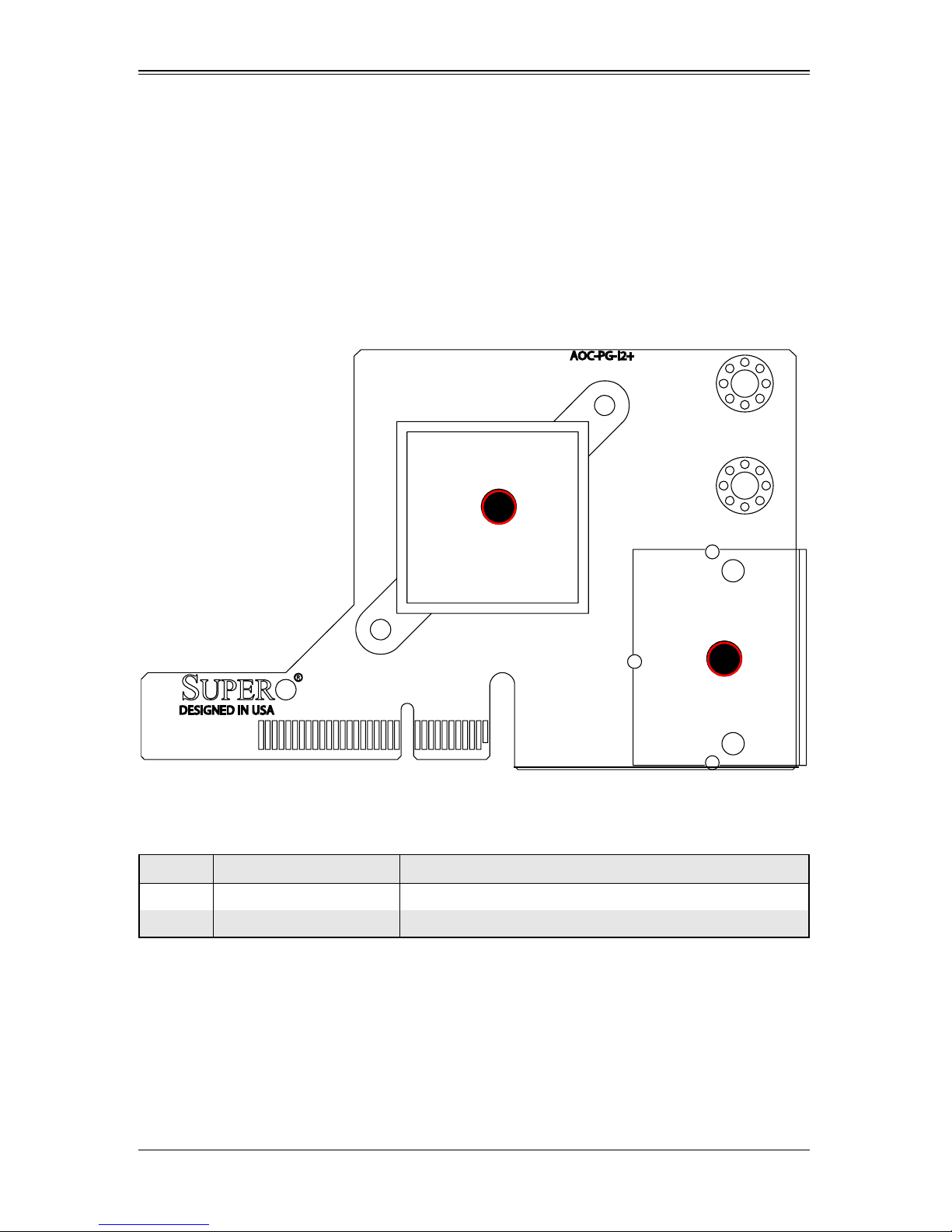
Figure 2-1 shows the front components of the AOC-PG-i2+ add-on card.
Figure 2-1. AOC-PG-i2+ Add-on Card Front Connectors and Jumpers
2
Table 2-1 lists the add-on card’s front components and their description.
Table 2-1. Front Connectors and Pin Definitions
Number Name Description
1 LAN Connector Ports (2) Housing with two RJ-45 connectors.
2 Intel 82576 chip Intel LAN chip
1
2-1
Page 12

AOC-PG-i2+ Add-on Card User’s Manual
2-2 Front Connectors, Jumpers and LEDs
This section describes the front connectors, jumpers and LEDs found on the
AOC-PG-i2+ add-on card.
LAN Ports
LAN ports allow the add-on card to connect to a maximum of two network cables. These
are RJ-45 connectors. Each LAN port provides up to one gigabit per second connection
speed which require CAT6 cables for maximum throughput.
The ports are designated LAN1 and LAN2.
LAN Port LEDs
Each LAN port includes two LEDs. The LEDs indicate connection speed and activity.
See Table 2-2 and Table 2-3 for definitions of these LEDs.
NOTE: Different manufacture of RJ45 Connectors after February 2010 has led
to changes in the type and characteristics of LED’s used for this add-on card.
See the tables below for these differences.
Table 2-2. LAN Port LEDs Before January 2010
LED Color Definition
Activity Amber (blinking) LAN Activity
Orange Link speed in 1000-Mb/s
Link
Green Link speed in 100-Mb/s
Off No connection or link speed at 10-Mb/s
Table 2-3. LAN Port LEDs After February 2010
LED Color Definition
Activity Green (blinking) LAN Activity
Link
Green Link speed in 1000-Mb/s
Off Link speed in 10/100-Mb/s
2-2
Page 13
Chapter 2: Card Components
2-3 Riser Card
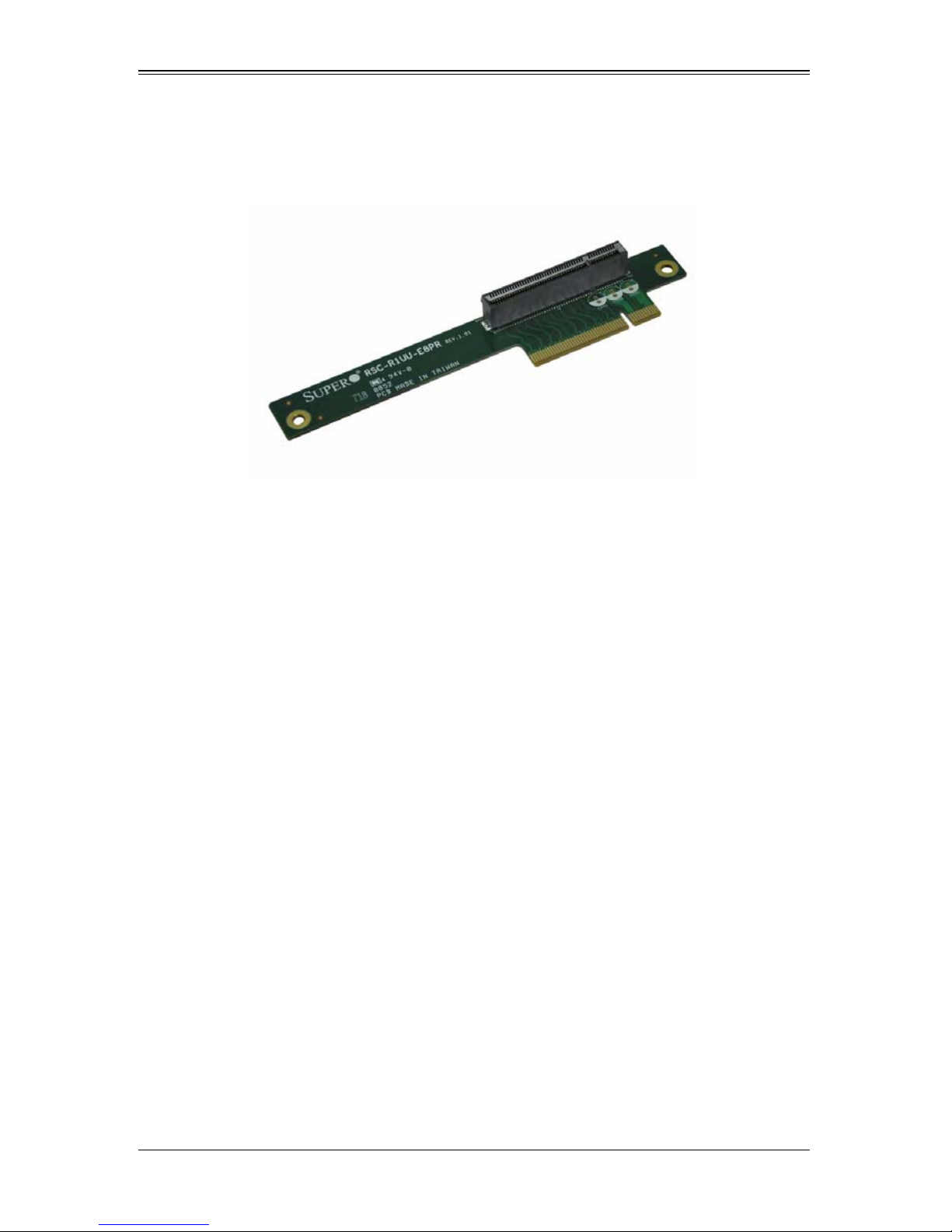
Figure 2-2. RSC-R1UU-E8PR Riser Card
The AOC-PG-i2+ add-on card requires a RSC-R1UU-E8PR riser card for connection to
supported systems (Figure 2-2).
2-3
Page 14
AOC-PG-i2+ Add-on Card User’s Manual
2-4 System Installation
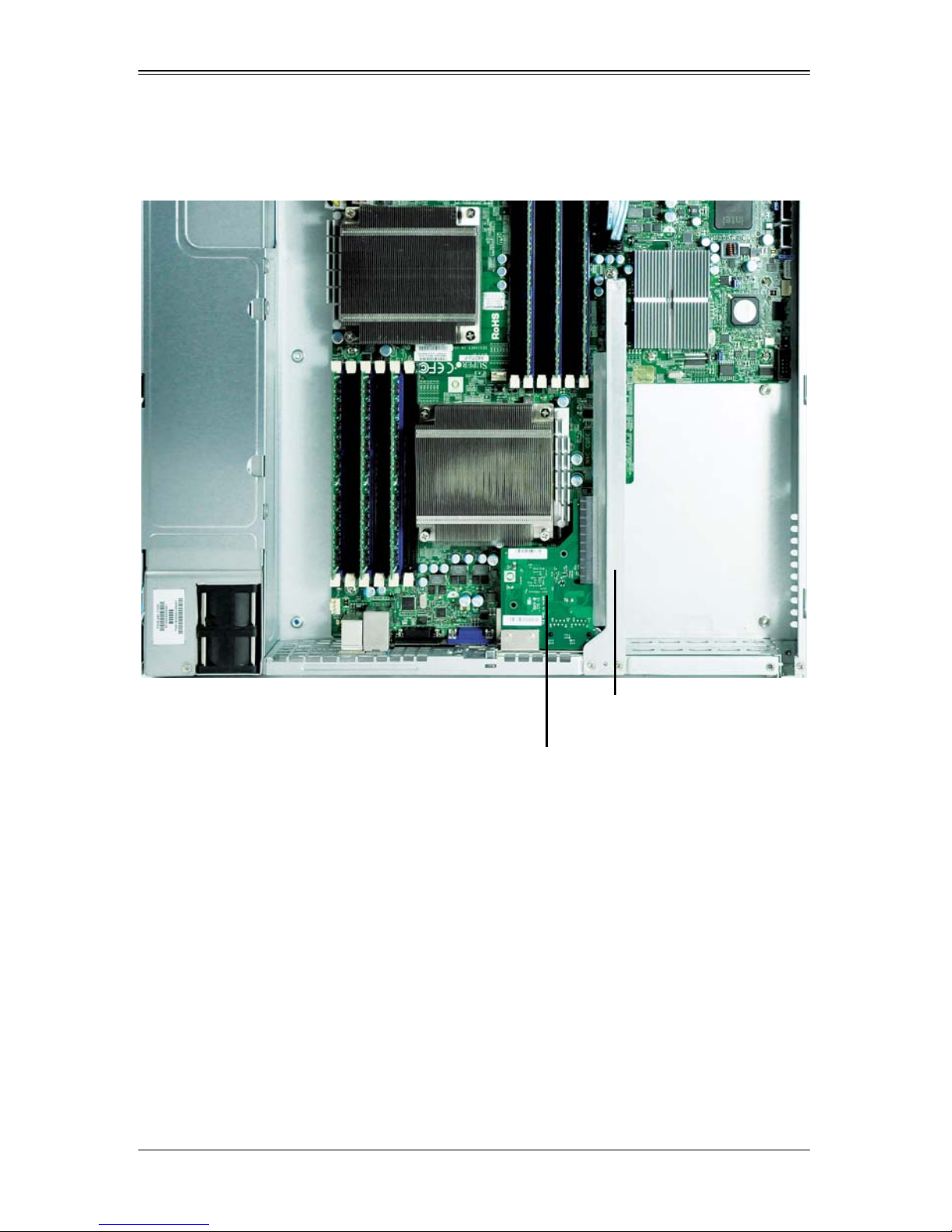
Figure 2-3. Add-on and Riser Cards in System
RSC-R1UU-E8PR
Riser Card
AOC-PG-i2+
Add-on Card
The AOC-PG-i2+ add-on card and RSC-R1UU-E8PR riser card are installed in a PCI-E
slot on the mainboard of the system. Simply connect the AOC-PG-i2+ add-on card to
the RSC-R1UU-E8PR riser card and install the riser card into the PCI-E slot on the
mainboard (Figure 2-3).
Once installed in the PCI-E slot, simply connect your LAN cables to the ports provided
on the side of the chassis (see Figure 2-4).
2-4
Page 15
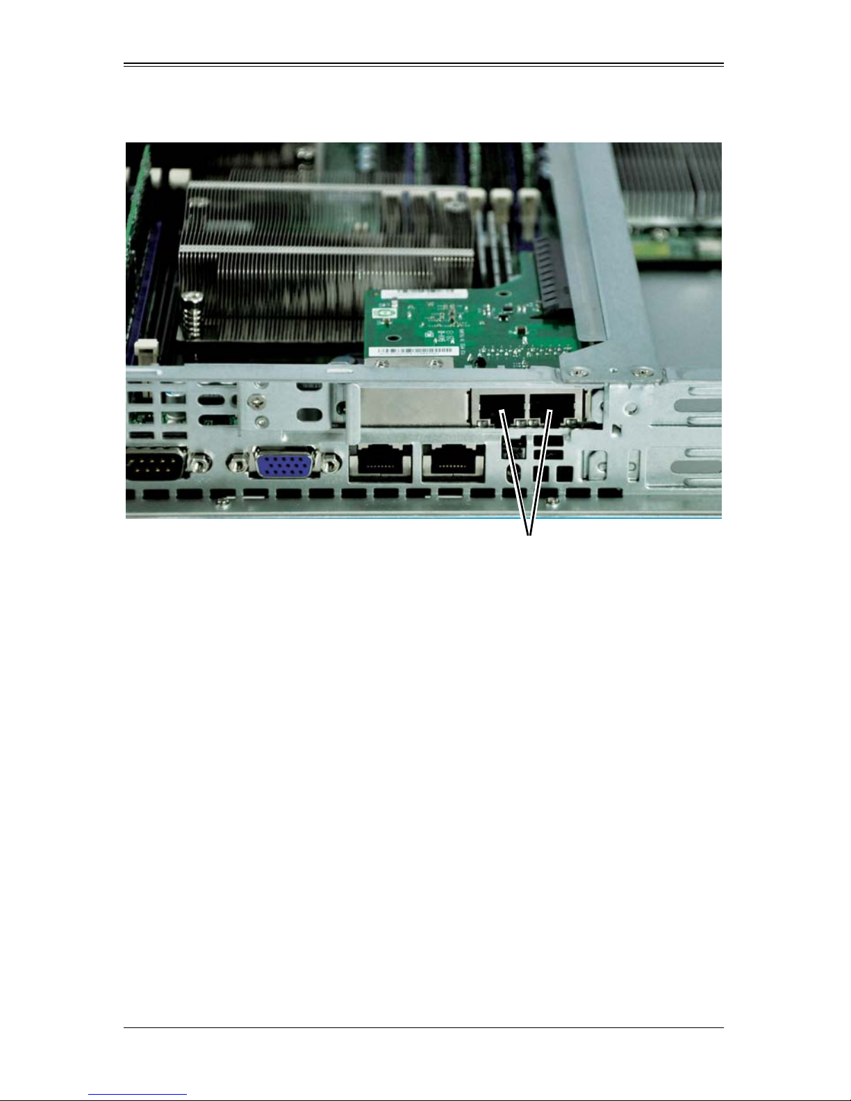
Chapter 2: Card Components
Figure 2-4. Side View of Add-on Card in System
AOC-PG-i2+
Add-on Card
LAN Ports
2-5
Page 16

AOC-PG-i2+ Add-on Card User’s Manual
2-6
Page 17

Chapter 3
Installing the Drivers
3-1 Installing the Drivers in Microsoft Windows
These instructions apply to all versions of Microsoft™ Windows™ 2000, Windows XP
(including Windows XP x64 and Windows XP 64-bit Edition), Windows Vista™
(including Windows Vista x64), and Windows Server™ 2003 (including Windows Server
2003 x64 and Windows Server 2003 64-Bit Edition).
This driver installation updates the drivers for all supported Intel® PRO network
adapters in your system.
Before installing or updating the drivers, insert your adapter(s) in the computer and plug
in the network cable. When Windows discovers the new adapter, it attempts to find an
acceptable Windows driver already installed with the operating system. If found, the
driver is installed without any user intervention. If Windows cannot find the driver, the
Found New Hardware Wizard window is displayed.
Regardless of whether or not Windows finds the driver, it is recommended that you
follow the procedure below to install the driver. The controller comes with driver on the
CD-ROM CDR-NIC.
Installing the Drivers
1. If you are installing drivers from the Product CD, insert the CDR-NIC.
If you do not have the Product CD, download drivers from the support web site and
transfer them to the system.
2. If the F
3. SUPERMICRO window appears on the screen.
Click on the computer button next to AOC-PG-I2+.
4. Click on I
5. Follow the prompts on screen to complete the installation.
OUND NEW HARDWARE WIZARD screen is displayed, click CANCEL.
NSTALL DRIVERS AND SOFTWARE.
3-2 Intel PROSet for Windows Device Manager
Intel® PROSet for Windows™ Device Manager is an extension to the Windows Device
Manager. When you install the Intel PROSet software, additional tabs are automatically
added to Device Manager. You can install Intel PROSet on computers running Microsoft
Windows 2000, Windows XP, Windows Vista, and Windows Server* 2003, including
64-bit and x64 versions.
3-1
Page 18

AOC-PG-i2+ Add-on Card User’s Manual
NOTE: You must have administrator rights to install or use Intel PROSet for
Windows Device Manager.
Installing Intel PROSet for Windows Device Manager
Intel PROSet for Windows Device Manager is installed from the Product CD with the
same process used to install drivers. You can select Intel PROSet for Windows Device
Manager and Advanced Network Services from the Install Options dialog.
Tips for PROSet Users
If you have used prior versions of Intel PROSet, you should be aware of the following
changes with Intel PROSet for Windows Device Manager:
With PR OSet:
• There is no system tray icon.
• The configuration utility is not accessible from the C
menu.
• All Intel PROSet features are now accessed from D
features, simply open the D
would like to configure.
EVICE MANAGER and double-click the Intel adapter you
ONTROL PANEL or the START
EVICE MANAGER. To access
Removing Intel PROSet for Windows Device Manager
Use ADD/REMOVE PROGRAMS from the CONTROL PANEL to uninstall Intel PROSet for
Windows Device Manager.
Receive Side Scaling
RSS must be enabled for Intel® I/O Acceleration Technology to function. You must also
install Microsoft’s Scalable Networking Pack (SNP) for RSS to function. Intel® PROSet
will not display the RSS setting if SNP is not installed.
NOTE: The Scalable Networking Pack is part of Microsoft Windows Server
2003 Service Pack 2. It is not part of Service Pack 1, therefore it requires a
separate download. See http://www.microsoft.com for more information.
RSS Configuration
RSS is enabled on the Advanced tab of the adapter property sheet. If your adapter does
not support RSS, or if the SNP is not installed, the RSS setting will not be displayed.
Teaming
Some RSS teaming considerations are as follows:
3-2
Page 19

Chapter 3: Installing the Drivers
• If RSS is not enabled for all adapters in a team, RSS will be disabled for the team.
• If an adapter that does not support RSS is added to a team, RSS will be disabled for
the team.
• If a non-Intel adapter is added to a team, RSS will be disabled for the team.
• Non-Intel adapters with RSS enabled cannot be added to a team.
3-3 Installing the Base Driver and Intel PROSet via the
Command Line
Installation Methods
The base driver install utility (SetupBD.exe) allows unattended install of base drivers
from a command line.
®
Intel
PROSet for Windows™ Device Manager is supported on Microsoft™ Windows™
2000, Windows XP, Windows Vista, and Microsoft Windows Server* 2003. Use
DxSetup.exe to Install PROSet for Windows Device Manager.
NOTE: Windows XP x64 and Windows Server 2003 x64 do not support
unattended driver installation.
Base Driver Installation
Driver installation is started by running the SetupBD.exe file.
Command Line Options
SetupBD.exe supports the following command line switches and options as shown in
Table 3-1 and Table 3-2.
Table 3-1. SetupBD.exe Switches
Switch Description
/s Silent install with no boot
/r Force reboot (must be used with the /s switch)
/nr
/u Uninstall
No reboot (must be used with the /s switch)
This switch is ignored if it is included with the /r switch
/infdir directory_name Search for INF and driver files only in the specified directory
3-3
Page 20

AOC-PG-i2+ Add-on Card User’s Manual
Table 3-2. SetupBD.exe Options
Option Description
SetupBD Installs and/or updates the driver(s) and displays the GUI.
SetupBD /s Installs and/or updates the driver(s) silently.
SetupBD /s /r Installs and/or updates the driver(s) silently and forces a reboot.
SetupBD /s /r /nr
SetupBD /u Uninstalls all drivers from the system.
SetupBD /infdir x:\infdir
Installs and/or updates the driver(s ) silently and forces a reboot (/nr is
ignored).
Installs and/or updates the driver(s), looks for INF and driver files only in
the specified directory
NOTE: You must include a space between switches.
In addition, the following considerations should be noted when running SetupBD.exe for
the driver installation:
• If you uninstall an adapter’s driver from Windows Device Manager, you must reboot
before using SetupBD.exe to install a new driver.
• If you install drivers on a system based on the Intel® 5000 Series Chipset, the /s
switch (silent install) forces a reboot without the /r switch. If you do not want the
system to reboot, use the /nr switch.
• For Intel® I/O Acceleration Technology to function properly, you must reboot after
driver installation.
• You can use the /r and /nr switches only with a silent install (such as with the “/s”
option).
Intel PROSet for Windows Device Manager Installation
This section describes how to install Intel PROSet for Windows Device Manager from
the command line.
NOTE: Intel PROSet can be installed with DxSetup.exe or msiexec.exe. Intel
recommends using DxSetup.exe. DxSetup.exe detects the system’s language,
searches for the appropriate transform file, and applies it to MSI package. The
transform file translates the installation instructions to the language associated
with your operating system.
3-4
Page 21

Chapter 3: Installing the Drivers
Using the DxSetup.exe Utility
DxSetup.exe is a setup utility used for installing Intel PROSet. It detects the system
language, searches for the appropriate transform file in the same folder, and then
launches PROSETDX.msi in the language specific to the operating system. The
transform file translates the installation instructions to the language associated with your
operating system.
Table 3-3 displays and describes DxSetup.exe switches, while Table 3-4 describes its
public properties.
Table 3-3. DxSetup.exe Switches
Switch Description
Silent install options:
/q[r|n]
/l[i|w|e|a]
• r - Reduced GUI install
• n - Silent install
Log file options:
• i - Log status messages
• w - Log non-fatal warnings
• e - Log error messages
• a - Log the start of all actions
Table 3-4. DxSetup.exe Public Properties
Switch Description
Property settings are:
• 0 - Deselect / do not execute SetupBD
BD
1
ANS
DMIX
1. The ANS property should only be set to ANS=1 if DMIX=1 is set. If DMIX=0 and ANS=1, th e ANS=1 is
ignored and only the base driver will be installed.
DxSetup.exe also takes the install options from the command line and applies them to
the PROSETDX.msi command line installation.
• 1 - Execute SetupBD to install the drivers (default sett ing)
NOTE: BD should only be set to 0 if the Base Drivers have already been
installed prior to running DxSetup.exe.
Property settings are:
• 0 - Deselect / hide ANS
• 1 - Select ANS (default setting)
Property settings are:
• 0 - Deselect / hide Intel PROSet feature
• 1 - Select Intel PROSet feature (default setting)
3-5
Page 22

AOC-PG-i2+ Add-on Card User’s Manual
NOTE: Public properties are case sensitive. All characters are uppercase with
no white space between characters. For example:
DxSetup.exe /qn ANS=1
Any white space in “ANS=1” makes the setting invalid. “ans=1” is not a valid
setting.
Command Line Examples
You can modify the paths for different operating systems and CD layouts and apply the
following command line examples:
Launches a Typical Install Silently:
• DxSetup.exe /qn /liew
• C:\install.log
NOTE: BD, ANS and DMIX are selected by default.
Installing Components but Deselecting ANS, Setting ANS=0:
• DxSetup.exe /qn ANS=0 /liew
• C:\install.log
msiexec.exe Command Line Options
Refer to Microsoft’s web site (http://msdn.microsoft.com/library) for the most current
information on msiexec.exe command line options.
Please note though that:
• Not all command line options Microsoft provides with msiexec.exe have been tested
or are necessarily supported for Intel PROSet installation.
• Msiexec also sets an error level on return that corresponds to system error codes.
For further details, see: http://msdn.microsoft.com/library on the Microsoft web site.
3-6
Page 23

Command Line Switches
Table 3-5. Command Line Switches
Switch Description
/i Install
/x Uninstall
Silent install options:
/q[r|n]
/l[i|w|e|a]
Transforms
• r - Reduced GUI Install
• n - Silent install
Log file options:
• i - Log status messages.
• w - Log non-fatal warnings.
• e - Log error messages.
• a - Log the start of all actions.
A property used to apply transforms (a *.mst file) to an MSI package. The
following example applies a Chinese language transform to MSI package,
so the installer displays Chinese strings during installation:
TRANSFORMS=2052.mst
Chapter 3: Installing the Drivers
This section describes how to install Intel PROSet using PROSETDX.msi and
msiexec.exe from the command line. For more information on msiexec.exe command
line parameters, refer to the msiexec.exe command line options section.
Windows Installer Service is installed by default in Windows 2000, XP32 and XP64.
msiexec.exe is under System32 folder. When System32 is not in the current PATH, the
full path to msiexec.exe should be specified in the command line. For example:
• C:\WINNT\System32\msiexec.exe /i
• PROSETDX.msi /qn /liew
• c:\temp\install.log
Most commonly used msiexec.exe command line options are silent install/upgrade
command line syntax and Silent Uninstall Command Line Syntax.
Silent Install/upgrade Command Line Syntax
The following launches a typical installation of PROSETDX.msi.
<Full path to msiexec.exe> /i <Full path to PROSETDX.msi> /qn
/liew <Full path to install.log>
Silent Uninstall Command Line Syntax
The following uninstalls all the Intel PROSet components. It can be used when the path
to PROSETDX.msi is available.
<path to msiexec.exe> /x <path to PROSETDX.msi> /qn /liew
<path to uninstall.log>
3-7
Page 24

AOC-PG-i2+ Add-on Card User’s Manual
Table 3-6. Property Settings
Property Description
Property settings are:
• 0 - Deselect / do not execute SetupBD.
BD
ANS
The following uninstalls all the Intel PROSet components. It can be used when the path
to PROSETDX.msi is not available but the ProductCode of MSI package is known.
<path to msiexec.exe> /x <ProductCode of PROSETDX.msi> /qn /
liew <path to uninstall.log>
• 1 - Execute SetupBD to install the drivers.
NOTE: In this release, it is set to “1” by default. It is always installed by
default in this release. BD should only be set to 0 if the Base Drivers have
already been installed prior to running PROSETDX.msi.
Property Settings are:
• 0 - Deselect / hide ANS.
• 1 - Select ANS.
NOTE: In this release, it is set to “1” by default. It is always installed by
default in this release.
Command Line Options Supported by PROSETDX.msi
PROSETDX.msi provides public properties that can be used to change Intel PROSet
install selections from the command line.
By setting the properties in the command line, you can disable and hide some features
in PROSETDX.msi, or force some feature to be selected/displayed. This provides the
flexibility to install different components/features in Intel PROSet.
Following is the list of public properties provided by PROSETDX.msi:
• The ANS property should only be set to ANS=1 if DMIX=1 is set. If DMIX=0 and
ANS=1, only the base driver will be installed.
• Public properties are case sensitive. All characters are uppercase with no white
space between characters. For example:
msiexec.exe /i PROSETDX.msi /qn ANS=1
Any white space in “ANS=1” makes the setting invalid. “ans=1” is not a valid setting.
Command Line Install Examples
Assume that C:\WINNT\System32 is in the system32 folder and PROSETDX.msi is
under the D:\Apps\PROSETDX\Win32 folder. You can modify the paths for different
operating systems and CD layouts and apply the command line examples.
Command Line Examples
Installing Intel PROSet Silently on Windows XP:
C:\WINNT\System32\msiexec.exe /i
D:\Apps\PROSETDX\Win32\PROSETDX.msi /qn /liew C:\ install.log
3-8
Page 25

Chapter 3: Installing the Drivers
Installing Intel PROSet Silently on Windows Server 2003 for Itanium®-Based
Systems:
C:\WINNT\System32\msiexec.exe /i
D:\Apps\PROSETDX\Win64\PROSETDX.msi /qn /liew C:\ install.log
Installing Components but Deselecting ANS:
Set the ANS=0 in the command line, for example:
C:\WINNT\System32\msiexec.exe /i
D:\Apps\PROSETDX\Win32\PROSETDX.msi /qn ANS=0 /liew C:\
install.log
Applying a Transform File to MSI Using msiexec.exe:
Set the TRANSFORMS=filename.mst in the command line. For example:
C:\WINNT\System32\msiexec.exe /i
D:\Apps\PROSETDX\Win32\PROSETDX.msi /qn TRANSFORMS=2052.mst /
liew C:\ install.log
NOTE: Intel recommends using DxSetup.exe to install Intel PROSet since it
detects the system’s language, searches for the appropriate transform file, and
applies it to MSI package.
Command Line Uninstall Example
NOTE: Do not use the “ANS” option when uninstalling Intel PROSet from a
command line.
First get the path of PROSETDX.msi in the local system or any other image path when
you installed Intel PROSet, then use msiexec.exe to uninstall Intel PROSet.
For example, assume System folder is C:\Windows\System, and PROSETDX.msi is in
d:\unattend, then the command line will be:
C:\Windows\System\msiexec.exe /x d:\unattend\ PROSETDX.msi /
qn /liew d:\unattend\uninst.log
Command Line Reinstall/Repair
If you need to repair an Intel PROSet installation, uninstall the application and then
reinstall it. See the uninstall and install examples above for more information.
3-9
Page 26

AOC-PG-i2+ Add-on Card User’s Manual
Notes
3-10
Page 27

Chapter 4: Linux Base Driver for the PRO/1000 Family of Adapters
Chapter 4
Linux Base Driver for the
PRO/1000 Family of Adapters
4-1 Overview
This chapter describes the Linux* Base Driver for the Intel® PRO/1000 Family of
Adapters. This driver supports the 2.4.x and 2.6.x kernels. This driver includes support
for Itanium
This driver is only supported as a loadable module. Intel is not supplying patches
against the kernel source to allow for static linking of the driver. For questions related to
hardware requirements, refer to the documentation supplied with your Intel PRO/1000
adapter. All hardware requirements listed apply to use with Linux.
This release includes support for Intel I/O Acceleration Technology, Intel I/OAT. This is
supported on systems using the Intel 5000 Series Chipsets Integrated Device - 1A38.
You can find additional information on Intel I/OAT at:
®
2-based systems.
http://www.intel.com/technology/ioacceleration/index.htm
The following features are now available in supported kernels:
• Native VLANs
• Channel Bonding (teaming)
•SNMP
Channel Bonding documentation can be found in the Linux kernel source:
/documentation/networking/bonding.txt
The driver information previously displayed in the /proc file system is not supported in
this release. Alternatively , you can use ethtool (version 1.6 or later), lspci, and ifconfig to
obtain the same information. Instructions on updating ethtool can be found in the
Section 4-5: "Additional Configurations" on page 4-9.
4-2 Identifying Your Adapter
For more information on how to identify your adapter, go to the Adapter & Driver ID
Guide at:
http://support.intel.com/support/network/adapter/pro100/21397.htm
For the latest Intel network drivers for Linux, refer to the following website. In the search
field, enter your adapter name or type, or use the networking link on the left to search for
your adapter:
http://downloadfinder.intel.com/scripts-df/support_intel.asp
4-1
Page 28

AOC-PG-i2+ Add-on Card User’s Manual
4-3 Building and Installation
To build a binary RPM* package of this driver, run
rpmbuild -tb <filename.tar.gz>
Replace <filename.tar.gz> with the specific file name of the driver.
NOTE: For the build to work properly, the currently running kernel MUST match
the version and configuration of the installed kernel sources. If you have just
recompiled the kernel reboot the system now.
NOTE: PM functionality has only been tested in Red Hat distributions.
Building a Binary RPM Package
1. Move the base driver tar file to the directory of your choice. For example, use
/home/username/e1000 or /usr/local/src/e1000.
2. Untar/unzip the archive, where <x.x.x> is the version number for the driver tar file:
tar zxf e1000-<x.x.x>.tar.gz
3. Change to the driver src directory, where <x.x.x> is the version number for the driver
tar:
cd e1000-<x.x.x>/src/
4. Compile the driver module:
make install
The binary will be installed as:
/lib/modules/<KERNEL VERSION>/kernel/drivers/net/e1000/
e1000.[k]o
The install location listed above is the default location. This may differ for various
Linux distributions. For more information, go to ldistrib.htm.
5. Load the module using either the insmod or modprobe command:
modprobe e1000
insmod e1000
Note that for 2.6 kernels the insmod command can be used if the full path to the
driver module is specified. For example:
insmod /lib/modules/<KERNEL VERSION>/kernel/drivers/net/
e1000/e1000.ko
With 2.6 based kernels also make sure that older e1000 drivers are removed from
the kernel, before loading the new module:
4-2
Page 29

Chapter 4: Linux Base Driver for the PRO/1000 Family of Adapters
rmmod e1000; modprobe e1000
6. Assign an IP address to the interface by entering the following, where <x> is the
interface number:
ifconfi g eth<x> <IP_address>
7. Verify that the interface works. Enter the following, where <IP_address> is the IP
address for another machine on the same subnet as the interface that is being
tested:
ping <IP_address>
4-4 Command Line Parameters
If the driver is built as a module, the following optional parameters are used by entering
them on the command line with the modprobe command using this syntax:
modprobe e1000 [<option>=<VAL1>,<VAL2>,...]
For example, with two PRO/1000 PCI adapters, entering:
modprobe e1000 TxDescriptors=80,128
loads the e1000 driver with 80 TX descriptors for the first adapter and 128 TX
descriptors for the second adapter.
The default value for each parameter is generally the recommended setting, unless
otherwise noted.
NOTE: For more information about the AutoNeg, Duplex, and Speed
parameters, see the Speed and Duplex Configuration section in this document.
For more information about the InterruptThrottleRate, RxIntDelay, TxIntDelay,
RxAbsIntDelay and TxAbsIntDelay parameters, see the application note at:
http://www.intel.com/design/network/applnots/ap450.htm
A descriptor describes a data buffer and attributes related to the data buffer.
This information is accessed by the hardware.
4-3
Page 30

AOC-PG-i2+ Add-on Card User’s Manual
Table 4-1. Command Line Parameter Settings
Parameter
Name
AutoNeg
Duplex
FlowControl
Interrupt ThrottleRate
Valid Range/
Settings
0x01-0x0F,
0x20-0x2F
0-2
(0=auto-negotiate,
1=half, 2=full)
0-3
(0=none, 1=Rx
only, 2=Tx only,
3=Rx&Tx)
(not supported on
Intel(R) 82542,
82543 or
82544-based
adapters)
Valid Range:
0,1,3,100-100000
(0=off,
1=dynamic,
3=dynamic
conservative)
Default Description
This parameter is a bit mask that specifies which
speed and duplex settings the board advertises.
When this parameter is used, the Speed and
Duplex parameters must not be specified.
0x2F
0
Read flow
control
settings from
the EEPROM
3
This parameter is supported only on ada pters using
copper connections.
NOTE: Refer to the Speed and Duplex section of
this readme for more information on the AutoNeg
parameter
Defines the direction in which data is allowed to
flow. Can be either one or two-directional. If both
Duplex and the link partner are set to
auto-negotiate, the board auto-detects the correct
duplex. If the link partner is forced (either full or
half), Duplex defaults to half-duplex.
This parameter is supported only on ada pters using
copper connections.
This parameter controls the automatic
generation(Tx) and response(Rx) to Ethernet
PAUSE frames.
Since 7.3.x, the driver has two adaptive modes
(setting 1 or 3) in w hi c h it dynamically adjusts the
InterruptThrottleRate value base d on the traf fic t hat
it receives. After determining the type of incoming
traffi c in the last timeframe, it will adjust the
InterruptThrottleRate to an appropriat e value for
that traffic.
The algorithm classifies the incoming traffic every
interval into classes. Once the class is det er mined,
the InterruptThrottleRate value is adjusted to suit
that traffic type the best.
There are three classes defined:
• Bulk traffic – for large amounts of packets of
normal size
• Low latency – for small amounts of traffic and/
or a significant percentage of small packets
• Lowest latency – for almost completely small
packets or minimal traffic
In dynamic conservative mode, the
InterruptThrottleRate value is set to 4000 for traffic
that falls in class “Bulk traffic”. If traffic falls in the
“Low latency” or “Lowest latency” class, the
InterruptThrottleRate is increased stepwise to
20000. This default mode is suitable for most
applications.
See the Footnote
information.
.
1
at the end of this table for more
4-4
Page 31

Chapter 4: Linux Base Driver for the PRO/1000 Family of Adapters
Table 4-1. Command Line Parameter Settings (Continued)
Parameter
Name
RxDescriptors
RxIntDelay 0-65535 (0=off) 0
Valid Range/
Settings
80-256 for 82542
and 82543-based
adapters
80-4096 for all
other supported
adapters
Default Description
256
This value specifies the number of receive buffer
descriptors allocated by the driver. Increasing this
value allows the driver to buffer more incoming
packets, at the expense of increased syste m
memory utilization.
Each descriptor is 16 bytes. A receive buffer is also
allocated for each descriptor and can be either
2048, 4096, 8192, or 16384 bytes, depending on
the MTU setting. The maximum MTU size is 16110.
NOTE: MTU designates the frame size, and it only
needs to be set for Jumbo Frames. Depending on
the available system resources, the request for a
higher number of receive descriptors may be
denied. In this case, use a lower number.
This value delays the generation of receive
interrupts in units of 1.024 microseconds. Receive
interrupt reduction can improve CPU efficiency if
properly tuned for specific network traffic.
Increasing this value adds extra latency to frame
reception and can end up decreasing the
throughput of TCP traffic. If the system is reporting
dropped receives, this value may be set too high,
causing the driver to run out of available receive
descriptors.
WARNING: When setting RxIntDelay to a value
other than 0, adapters may hang (stop transmitting)
under certain network conditions. If this occurs a
NETDEV WATCHDOG message is logged in the
system event log. In addition, the controller is
automatically reset, restoring the network
connection. To eliminate the potential for the hang
ensure that RxIntDelay is set to zero.
RxAbsIntDelay 0-65535 (0=off) 128
Speed 0, 10, 100, 1000 0
This value, in units of 1.024 microseconds, limits
the delay in which a receive interrupt is generated.
Useful only if RxIntDelay is non-zero, this value
ensures that an interrupt is generated after the
initial packet is received within the set amount of
time. Proper tuning, along with RxIntDelay, may
improve traffic throughput in specif ic network
conditions.
This parameter is supported only on 82540, 82545
and later adapters.
Speed forces the line speed to the specified value
in megabits per second (Mbps ). I f th is parameter is
not specified or is set to 0 and the link p artner is set
to auto-negotiate, the board will auto-detect the
correct speed. Duplex must also be set when
Speed is set to either 10 or 100.
This parameter is supported only on ada pters using
copper connections.
4-5
Page 32

AOC-PG-i2+ Add-on Card User’s Manual
Table 4-1. Command Line Parameter Settings (Continued)
Parameter
Name
TxDescriptors
TxIntDelay 0-65535 (0=off) 64
TxAbsIntDelay 0-65535 (0=off) 64
Valid Range/
Settings
80-256 for 82542
and 82543-based
adapters
80-4096 for all
other supported
adapters
Default Description
256
This value is the number of transmit descriptors
allocated by the driver. Increasing this value allows
the driver to queue more transmit s. Each descriptor
is 16 bytes.
This value delays the generation of transmit
interrupts in units of 1.024 microseconds. Transmit
interrupt reduction can improve CPU efficiency if
properly tuned for specific network traffic. If the
system is reporting dropped transmits, this value
may be set too high causing the dr iver to run out of
available transmit descriptors.
This value, in units of 1.024 microseconds, limits
the delay in which a transmit interrup t is gen erated.
Useful only if TxIntDelay is non-zero, this value
ensures that an interrupt is generated after th e
initial packet is sent on the wire within the set
amount of time. Proper tuning, along with
TxIntDelay, may improve traffic throughput in
specific network conditions.
This parameter is supported only on 82540, 82545
and later adapters.
A value of ‘1’ indicates that the driver should enable
IP checksum offload for received packets (both
XsumRX 0-1 1
UDP and TCP) to the adapter hardware.
This parameter is not supported on the
82542-based adapter.
1. InterruptThrottleRate takes precedence over the TxAbsIntDelay and RxAbsIntDelay
parameters. In other words, minimizing the receive and/or transmit absolute delays does
not force the controller to generate more interrupts than what the Interrupt Throttle Rate
allows.
Notes on InterruptThrottleRate
Since 7.3.x, the driver has two adaptive modes (setting 1 or 3) in which it dynamically
adjusts the InterruptThrottleRate value based on the traffic that it receives. After
determining the type of incoming traffic in the last time frame, it will adjust the
InterruptThrottleRate to an appropriate value for that traffic.
The algorithm classifies the incoming traffic every interval into classes. Once the class is
determined, the InterruptThrottleRate value is adjusted to suit that traffic type the best.
There are three classes defined: “Bulk traffic”, for large amounts of packets of normal
size; “Low latency”, for small amounts of traffic and/or a significant percentage of small
packets; and “Lowest latency”, for almost completely small packets or minimal traffic.
4-6
Page 33

Chapter 4: Linux Base Driver for the PRO/1000 Family of Adapters
In dynamic conservative mode, the InterruptThrottleRate value is set to 4000 for traffic
that falls in class “Bulk traffic”. If traffic falls in the “Low latency” or “Lowest latency”
class, the InterruptThrottleRate is increased stepwise to 20000. This default mode is
suitable for most applications.
For situations where low latency is vital such as cluster or grid computing, the algorithm
can reduce latency even more when InterruptThrottleRate is set to mode 1. In this
mode, which operates the same as mode 3, the InterruptThrottleRate will be increased
stepwise to 70000 for traffic in class “Lowest latency”.
Setting InterruptThrottleRate to 0 turns off any interrupt moderation and may improve
small packet latency, but is generally not suitable for bulk throughput traffic.
WARNING: If you are using the Intel(R) PRO/1000 CT Network Connection
(controller 82547), setting InterruptThrottleRate to a value greater than 75,000,
may hang (stop transmitting) adapters under certain network conditions. If this
occurs a NETDEV WATCHDOG message is logged in the system event log.
In addition, the controller is automatically reset, restoring the network
connection. To eliminate the potential for the hang, ensure that
InterruptThrottleRate is set no greater than 75,000 and is not set to 0.
NOTE: When e1000 is loaded with default settings and multiple adapters are in
use simultaneously, the CPU utilization may increase non-linearly. In order to
limit the CPU utilization without impacting the overall throughput, we
recommend that you load the driver as follows:
modprobe e1000 InterruptThrottleRate=3000,3000,3000
This sets the InterruptThrottleRate to 3000 interrupts/sec for the first, second,
and third instances of the driver. The range of 2000 to 3000 interrupts per
second works on a majority of systems and is a good starting point, but the
optimal value will be platform-specific. If CPU utilization is not a concern, use
RX_POLLING (NAPI) and default driver settings.
Speed and Duplex Configuration
Three keywords are used to control the speed and duplex configuration. These
keywords are Speed, Duplex, and AutoNeg.
If the board uses a fiber interface, these keywords are ignored, and the fiber interface
board only links at 1000 Mbps full-duplex.
For copper-based boards, the keywords interact as follows:
The default operation is auto-negotiate. The board advertises all supported speed
and duplex combinations, and it links at the highest common speed and duplex
mode IF the link partner is set to auto-negotiate.
If Speed = 1000, limited auto-negotiation is enabled and only 1000 Mbps is
advertised (The 1000BaseT spec requires auto-negotiation.)
4-7
Page 34

AOC-PG-i2+ Add-on Card User’s Manual
If Speed = 10 or 100, then both Speed and Duplex should be set. Auto-negotiation is
disabled, and the AutoNeg parameter is ignored. Partner SHOULD also be forced.
The AutoNeg parameter is used when more control is required over the auto-negotiation
process. It should be used when you wish to control which speed and duplex
combinations are advertised during the auto-negotiation process. The parameter may
be specified as either a decimal or hexadecimal value as determined by Table 4-2
below.
Table 4-2. AutoNeg Parameter Values
Bit Position Decimal Value Hex Value Speed (Mbps) Duplex
7 128 80 N/A –
6 64 40 N/A –
5 32 20 1000 Full
4 16 10 N/A –
3 8 8 100 Full
2 4 4 100 Half
12110Full
0 1 1 10 Half
Some examples of using AutoNeg:
modprobe e1000 AutoNeg=0x01 (Restricts autonegotiation to 10 Half)
modprobe e1000 AutoNeg=1 (Same as above)
modprobe e1000 AutoNeg=0x02 (Restricts autonegotiation to 10 Full)
modprobe e1000 AutoNeg=0x03 (Restricts autonegotiation to 10 Half or 10 Full)
modprobe e1000 AutoNeg=0x04 (Restricts autonegotiation to 100 Half)
modprobe e1000 AutoNeg=0x05 (Restricts autonegotiation to 10 Half or 100 Half)
modprobe e1000 AutoNeg=0x020 (Restricts autonegotiation to 1000 Full)
modprobe e1000 AutoNeg=32 (Same as above)
Note that when this parameter is used, Speed and Duplex must not be specified.
If the link partner is forced to a specific speed and duplex, then this parameter should
not be used. Instead, use the Speed and Duplex parameters previously mentioned to
force the adapter to the same speed and duplex.
4-8
Page 35

Chapter 4: Linux Base Driver for the PRO/1000 Family of Adapters
4-5 Additional Configurations
Configuring the Driver on Different Distributions
Configuring a network driver to load properly when the system is started is distribution
dependent. Typically, the configuration process involves adding an alias line to
/etc/modules.conf or /etc/modprobe.conf as well as editing other system startup scripts
and/or configuration files. Many popular Linux distributions ship with tools to make these
changes for you. To learn the proper way to configure a network device for your system,
refer to your distribution documentation. If during this process you are asked for the
driver or module name, the name for the Linux Base Driver for the Intel® PRO/1000
family of adapters is e1000.
As an example, if you install the e1000 driver for two PRO/1000 adapters (eth0 and
eth1) and set the speed and duplex to 10full and 100half, add the following to
modules.conf or /etc/modprobe.conf:
alias eth0 e1000
alias eth1 e1000
options e1000 Speed=10,100 Duplex=2,1
Viewing Link Messages
Link messages will not be displayed to the console if the distribution is restricting system
messages. In order to see network driver link messages on your console, set dmesg to
eight by entering the following:
dmesg -n 8
NOTE: This setting is not saved across reboots.
Jumbo Frames
Jumbo Frames support is enabled by changing the Maximum Transmission Unit (MTU)
to a value larger than the default value of 1500. Use the ifconfig command to increase
the MTU size. For example:
ifconfig eth<x> mtu 9000 up
This setting is not saved across reboots. The setting change can be made permanent by
adding MTU=9000 to the file: /etc/sysconfig/network-scripts/ifcfg-eth<x> (Red Hat
distributions). Other distributions may store this setting in a different location.
NOTE: To enable Jumbo Frames, increase the MTU size on the interface
beyond 1500.
4-9
Page 36

AOC-PG-i2+ Add-on Card User’s Manual
NOTE: The maximum MTU setting for Jumbo Frames is 16110. This value
coincides with the maximum Jumbo Frames size of 16128.
Some Intel gigabit adapters that support Jumbo Frames have a frame size limit of 9238
bytes, with a corresponding MTU size limit of 9216 bytes. The adapters with this
limitation are based on the Intel® 82571EB, 82572EI, 82573L and 80003ES2LAN
controllers. These correspond to the following product names:
Intel® PRO/1000 PT Server Adapter
Intel® PRO/1000 PT Desktop Adapter
Intel® PRO/1000 PT Network Connection
Intel® PRO/1000 PT Dual Port Server Adapter
Intel® PRO/1000 PT Dual Port Network Connection
Intel® PRO/1000 PF Server Adapter
Intel® PRO/1000 PF Network Connection
Intel® PRO/1000 PF Dual Port Server Adapter
Intel® PRO/1000 PB Server Connection
Intel® PRO/1000 PL Network Connection
Intel® PRO/1000 EB Network Connection with I/O Acceleration
Intel® PRO/1000 EB Backplane Connection with I/O Acceleration
Intel® PRO/1000 PT Quad Port Server Adapter
WARNING: Using Jumbo Frames at 10 or 100 Mbps may result in poor
performance or loss of link.
Adapters based on the Intel® 82542 and 82573V/E controller do not support Jumbo
Frames. These correspond to the following product names:
Intel® PRO/1000 Gigabit Server Adapter
Intel® PRO/1000 PM Network Connection
The following adapters do not support Jumbo Frames:
Intel® 82562V 10/100 Network Connection
Intel® 82566DM Gigabit Network Connection
Intel® 82566DC Gigabit Network Connection
Intel® 82566MM Gigabit Network Connection
Intel® 82566MC Gigabit Network Connection
Intel® 82562GT 10/100 Network Connection
Intel® 82562G 10/100 Network Connection
4-10
Page 37

Chapter 4: Linux Base Driver for the PRO/1000 Family of Adapters
Ethtool
The driver utilizes the Ethtool interface for driver configuration and diagnostics, as well
as displaying statistical information. Ethtool version 1.6 or later is required for this
functionality.
The latest release of Ethtool can be found at: http://sourceforge.net/projects/gkernel.
NOTE: Ethtool 1.6 only supports a limited set of ethtool options. Support for a
more complete Ethtool feature set can be enabled by upgrading Ethtool to
Ethtool-1.8.1.
Enabling Wake on LAN* (WoL)
WoL is configured through the Ethtool utility. Ethtool is included with all versions of Red
Hat after Red Hat 7.2. For other Linux distributions, download and install Ethtool from
the following website: http://sourceforge.net/projects/gkernel.
For instructions on enabling WoL with Ethtool, refer to the website listed above.
WoL will be enabled on the system during the next shut down or reboot. For this driver
version, in order to enable WoL, the e1000 driver must be loaded prior to shutting down
or suspending the system.
NOTE: Wake On LAN is only supported on port A for the following devices:
* Intel® PRO/1000 PT Dual Port Network Connection
* Intel® PRO/1000 PT Dual Port Server Connection
* Intel® PRO/1000 PT Dual Port Server Adapter
* Intel® PRO/1000 PF Dual Port Server Adapter
* Intel® PRO/1000 PT Quad Port Server Adapter
NAPI
NAPI (Rx polling mode) is supported in the e1000 driver. NAPI is enabled or disabled
based on the configuration of the kernel. To override the default, use the following
compile-time flags.
To enable NAPI, compile the driver module, passing in a configuration option:
make CFLAGS_EXTRA=-DE1000_NAPI install
To disable NAPI, compile the driver module, passing in a configuration option:
make CFLAGS_EXTRA=-DE1000_NO_NAPI install
See http://www.cyberus.ca/~hadi/usenix-paper.tgz for more information on NAPI.
4-11
Page 38

AOC-PG-i2+ Add-on Card User’s Manual
Notes
4-12
Page 39

Disclaimer
The products sold by Supermicro are not intended for and will not be used in life support
systems, medical equipment, nuclear facilities or systems, aircraft, aircraft devices,
aircraft/emergency communication devices or other critical systems whose failure to
perform be reasonably expected to result in significant injury or loss of life or
catastrophic property damage. Accordingly, Supermicro disclaims any and all liability,
and should buyer use or sell such products for use in such ultra-hazardous applications,
it does so entirely at its own risk. Furthermore, buyer agrees to fully indemnify, defend
and hold Supermicro harmless for and against any and all claims, demands, actions,
litigation, and proceedings of any kind arising out of or related to such ultra-hazardous
use or sale.
Page 40

AOC-PG-i2+ Add-on Card User’s Manual
Notes
 Loading...