

Supermicro 5130AD-T User Manual
High Performance
Desktop System
5130AD-T
USER'S MANUAL
Revision 1.0

The information in this User’s Manual has been carefully reviewed and is believed to be accurate. The vendor assumes
no responsibility for any inaccuracies that may be contained in this document, and makes no commitment to update
or to keep current the information in this manual, or to notify any person or organization of the updates. Please Note:
For the most up-to-date version of this manual, please see our website at
Super Micro Computer, Inc. ("Supermicro") reserves the right to make changes to the product described in this manual
at any time and without notice. This product, including software and documentation, is the property of Supermicro and/
or its licensors, and is supplied only under a license. Any use or reproduction of this product is not allowed, except
as expressly permitted by the terms of said license.
IN NO EVENT WILL Super Micro Computer, Inc. BE LIABLE FOR DIRECT, INDIRECT, SPECIAL, INCIDENTAL,
SPECULA TIVE OR CONSEQUENTIAL DAMAGES ARISING FROM THE USE OR INABILITY TO USE THIS PRODUCT
OR DOCUMENT ATION, EVEN IF ADVISED OF THE POSSIBILITY OF SUCH DAMAGES. IN PARTICULAR, SUPER
MICRO COMPUTER, INC. SHALL NOT HAVE LIABILITY FOR ANY HARDWARE, SOFTWARE, OR DATA STORED
OR USED WITH THE PRODUCT, INCLUDING THE COSTS OF REPAIRING, REPLACING, INTEGRATING,
INSTALLING OR RECOVERING SUCH HARDWARE, SOFTWARE, OR DATA.
Any disputes arising between manufacturer and customer shall be governed by the laws of Santa Clara County in the
State of California, USA. The State of California, County of Santa Clara shall be the exclusive venue for the resolution
of any such disputes. Supermicro's total liability for all claims will not exceed the price paid for the hardware product.
FCC Statement: This equipment has been tested and found to comply with the limits for a Class B digital device
pursuant to Part 15 of the FCC Rules. These limits are designed to provide reasonable protection against harmful
interference when the equipment is operated in a commercial environment. This equipment generates, uses, and can
radiate radio frequency energy and, if not installed and used in accordance with the manufacturer’s instruction manual,
may cause harmful interference with radio communications. Operation of this equipment in a residential area is likely
to cause harmful interference, in which case you will be required to correct the interference at your own expense.
www.supermicro.com.
California Best Management Practices Regulations for Perchlorate Materials: This Perchlorate warning applies only
to products containing CR (Manganese Dioxide) Lithium coin cells. “Perchlorate Material-special handling may apply.
See
www.dtsc.ca.gov/hazardouswaste/perchlorate”.
WARNING: Handling of lead solder materials used in this product may expose you to lead, a
chemical known to the State of California to cause birth defects and other reproductive harm.
The products sold by Supermicro are not intended for and will not be used in life support systems, medical equipment,
nuclear facilities or systems, aircraft, aircraft devices, aircraft/emergency communication devices or other critical
systems whose failure to perform be reasonably expected to result in signifi cant injury or loss of life or catastrophic
property damage. Accordingly, Supermicro disclaims any and all liability, and should buyer use or sell such products
for use in such ultra-hazardous applications, it does so entirely at its own risk. Furthermore, buyer agrees to fully
indemnify, defend and hold Supermicro harmless for and against any and all claims, demands, actions, litigation, and
proceedings of any kind arising out of or related to such ultra-hazardous use or sale.
Manual Revision 1.0
Release Date: February 08, 2017
Unless you request and receive written permission from Super Micro Computer, Inc., you may not copy any part of this
document. Information in this document is subject to change without notice. Other products and companies referred
to herein are trademarks or registered trademarks of their respective companies or mark holders.
Copyright © 2017 by Super Micro Computer, Inc.
All rights reserved.
Printed in the United States of America
System 5130AD-T User's Manual
Preface
About this Manual
This manual is written for professional system integrators and PC technicians. It provides
information for the installation and use of the SuperServer 5130AD-T. Installation and
maintenance should be performed by experienced technicians only.
Please refer to the 5130AD-T server specifi cations page on our website for updates on
supported memory, processors and operating systems (
Notes
For your system to work properly, please follow the links below to download all necessary
drivers/utilities and the user’s manual for your server.
http://www.supermicro.com).
• Supermicro product manuals: http://www.supermicro.com/support/manuals/
• Product drivers and utilities: ftp://ftp.supermicro.com
• Product safety info: http://www.supermicro.com/about/policies/safety_information.cfm
If you have any questions, please contact our support team at:
support@supermicro.com
T
his manual may be periodically updated without notice. Please check the Supermicro website
for possible updates to the manual revision level.
Warnings
Special attention should be given to the following symbols used in this manual.
Warning! Indicates important information given to prevent equipment/property damage
or personal injury.
Warning! Indicates high voltage may be encountered when performing a procedure.
3

Preface
Contents
Chapter 1 Introduction
1.1 Overview ...............................................................................................................................8
1.2 Unpacking the System .........................................................................................................8
1.3 System Features ..................................................................................................................9
1.4 Server Chassis Features ....................................................................................................10
Control Panel ....................................................................................................................10
Front and Rear Features................................................................................................... 11
1.5 Motherboard Layout ...........................................................................................................12
Quick Reference Table ......................................................................................................13
Chapter 2 Desktop Setup
2.1 Overview .............................................................................................................................15
2.2 Unpacking the System .......................................................................................................15
2.3 Warnings and Precautions! ................................................................................................15
Workstations Precautions ..................................................................................................15
2.4 Accessing the Inside of the System ...................................................................................16
Left Side and Right Side Covers ......................................................................................16
Front Bezel ........................................................................................................................17
Chapter 3 Maintenance and Component Installation
3.1 Removing Power ................................................................................................................18
3.3 Motherboard Components ..................................................................................................18
Processor and Heatsink Installation ..................................................................................18
Installing the LGA1151 Processor ................................................................................19
Installing a Heatsink ......................................................................................................21
Removing the Heatsink .................................................................................................23
Memory Installation ...........................................................................................................24
Memory Support ............................................................................................................24
Removing Memory Modules ..........................................................................................25
Memory Support ................................................................................................................26
Memory Population Guidelines .........................................................................................26
PCI Expansion Card Installation .......................................................................................27
Installing Expansion Cards................................................................................................27
Motherboard Battery .........................................................................................................28
4

System 5130AD-T User's Manual
3.4 Chassis Components .........................................................................................................29
Key Features .....................................................................................................................29
Hard Drives .......................................................................................................................30
System Cooling .................................................................................................................34
Water Cooled Heat Sink ...................................................................................................36
Air Flow .............................................................................................................................37
Dust Filters ........................................................................................................................37
Power Supply ....................................................................................................................38
Chapter 4 Motherboard Connections
4.1 Power Connections ............................................................................................................39
4.2 Headers and Connectors ...................................................................................................40
Front Control Panel .......................................................................................................43
Data Cables ...................................................................................................................45
Power Cables ................................................................................................................45
4.4 Jumpers ..............................................................................................................................48
Explanation of Jumpers .................................................................................................48
4.5 LED Indicators ....................................................................................................................51
Chapter 5 Software
5.1 OS Installation ....................................................................................................................52
Installing the Windows OS for a RAID System ................................................................52
Installing Windows to a Non-RAID System ......................................................................52
5.2 Driver Installation ................................................................................................................53
5.3 SuperDoctor
®
5 ...................................................................................................................54
Chapter 6 BIOS
6.1 Introduction .........................................................................................................................55
Starting BIOS GUI Setup Utility ........................................................................................55
6.2 Main Menu ..........................................................................................................................56
How To Change the Confi guration Data ...........................................................................57
How to Start the Setup Utility............................................................................................57
6.3 System Information ............................................................................................................58
6.4 CPU ....................................................................................................................................59
CPU Confi guration ............................................................................................................60
6.5 Memory ...............................................................................................................................74
6.6 Advanced ............................................................................................................................81
6.7 Thermal & Fan .................................................................................................................109
5

Preface
6.8 Save & Exit .......................................................................................................................111
6.9 BIOS Update ....................................................................................................................113
Appendix A BIOS Error Codes
A-1 BIOS Error Beep (POST) Codes ..................................................................................... 115
A-2 Additional BIOS POST Codes ..........................................................................................116
Appendix B Standardized Warning Statements for AC Systems
B.1 About Standardized Warning Statements ........................................................................117
Appendix C System Specifi cations
Appendix D UEFI BIOS Recovery
D.1 Overview ...........................................................................................................................138
D.2 Recovering the UEFI BIOS Image ...................................................................................138
D.3 Recovering the BIOS Block with a USB Device ..............................................................138
D.4 Dual Boot Block ..............................................................................................................141
BIOS Boot Block .............................................................................................................141
BIOS Boot Block Corruption Occurrence ......................................................................141
D.2 Steps to Reboot the System by switch JBR1 ..................................................................141
6

System 5130AD-T User's Manual
Contacting Supermicro
Headquarters
Address: Super Micro Computer, Inc.
980 Rock Ave.
San Jose, CA 95131 U.S.A.
Tel: +1 (408) 503-8000
Fax: +1 (408) 503-8008
Email: marketing@supermicro.com (General Information)
support@supermicro.com (Technical Support)
Website:
Europe
Address: Super Micro Computer B.V.
Tel: +31 (0) 73-6400390
Fax: +31 (0) 73-6416525
Email: sales@supermicro.nl (General Information)
Website:
Asia-Pacifi c
Address: Super Micro Computer, Inc.
www.supermicro.com
Het Sterrenbeeld 28, 5215 ML
's-Hertogenbosch, The Netherlands
support@supermicro.nl (Technical Support)
rma@supermicro.nl (Customer Support)
www.supermicro.nl
3F, No. 150, Jian 1st Rd.
Tel: +886-(2) 8226-3990
Fax: +886-(2) 8226-3992
Email: support@supermicro.com.tw
Website:
Zhonghe Dist., New Taipei City 235
Taiwan (R.O.C)
www.supermicro.com.tw
7
System 5130AD-T User's Manual
Chapter 1
Introduction
1.1 Overview
This chapter provides a brief outline of the functions and features of the 5130AD-T. The
5130AD-T is based on the C7Z270-PG motherboard and the GS5A-753K chassis.
In addition to the motherboard and chassis, several important parts that are included with
the system are listed below.
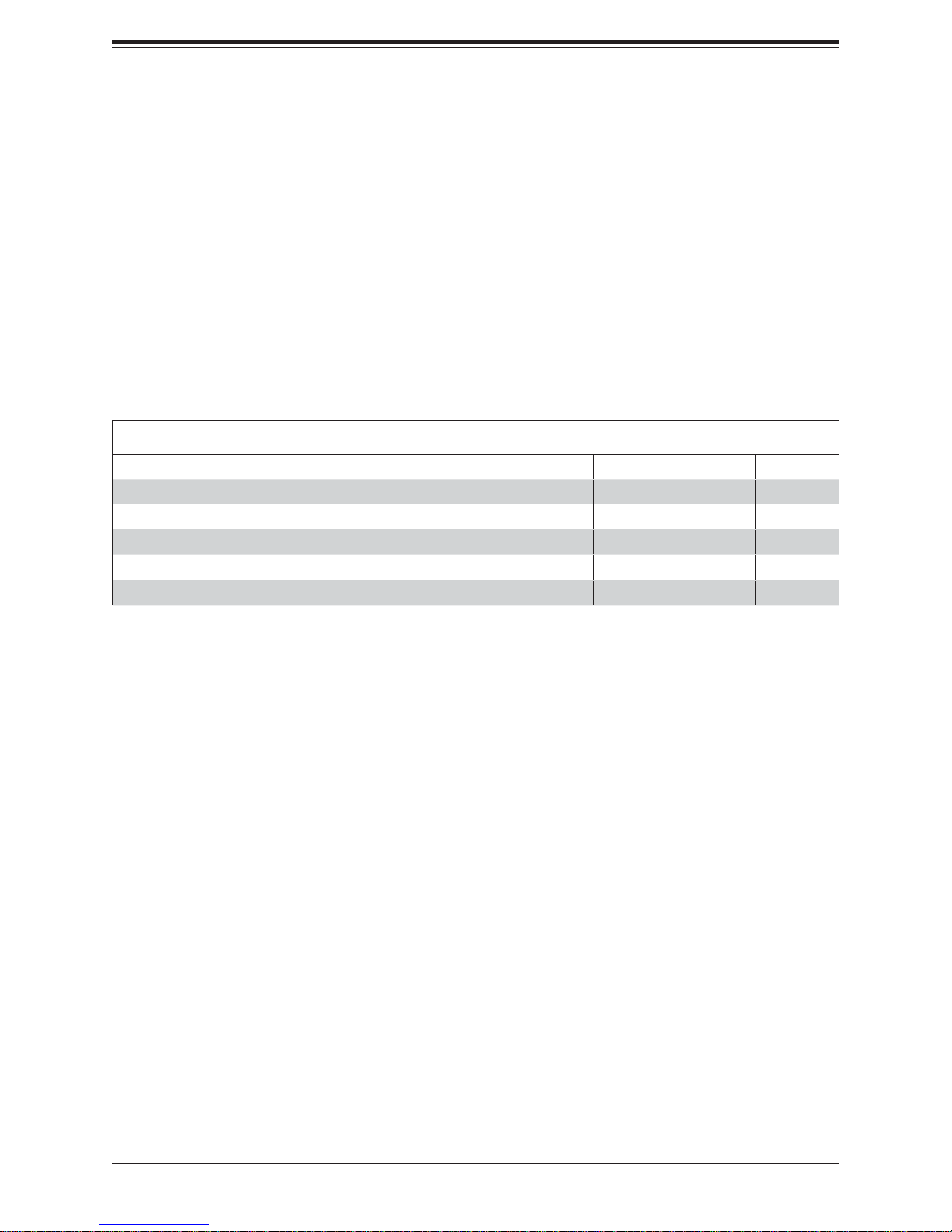
Main Parts List
Description Part Number Quantity
Rear exhaust fan
Front cooling fan
3.5" HDD cage for 3 drives MCP-220-GS504-0N
2.5" HDD cage for 4 drives MCP-220-GS505-0N
Optional active CPU heatsink
NA 1
NA 2
SNK-P0051AP4
2
1
1
1.2 Unpacking the System
Inspect the box the SuperServer 5130AD-T was shipped in and note if it was damaged in
any way. If any equipment appears damaged, please fi le a damage claim with the carrier
who delivered it.
Decide on a suitable location for the rack unit that will hold the server. It should be situated
in a clean, dust-free area that is well ventilated. Avoid areas where heat, electrical noise and
electromagnetic fi elds are generated. It will also require a grounded AC power outlet nearby.
Be sure to read the precautions and considerations noted in Appendix B.
8
Chapter 1: Introduction
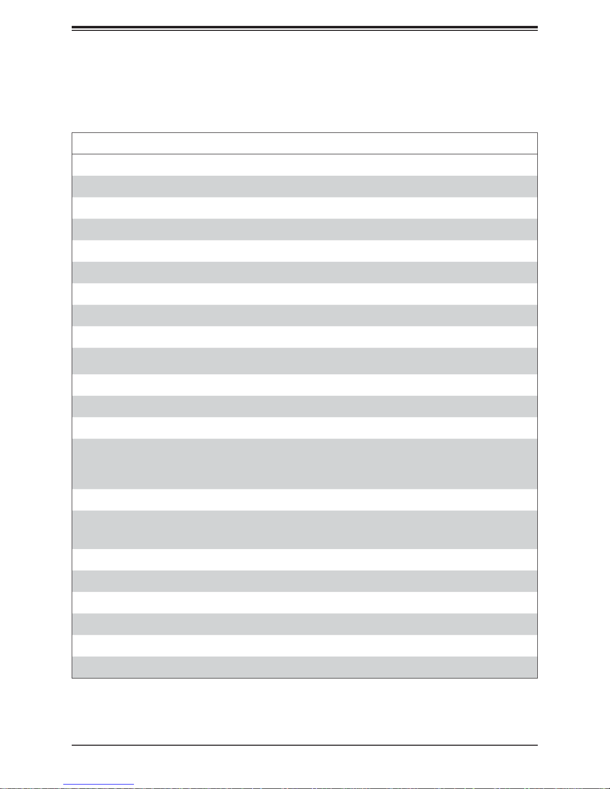
1.3 System Features
The following table provides you with an overview of the main features of the 5130AD-T.
Please refer to Appendix C for additional specifi cations.
System Features
Motherboard
C7Z270-PG
Chassis
GS5A-753K
CPU
Supports Intel® 7th/6th Gen Core i7/i5/i3 series processor
Socket Type
LGA 1151
Memory
Support up to 64 GB of unbuffered, non-ECC, 3600 MHz (OC) DDR4 memory in four (4) slots of
4GB, 8GB and 16GB UDIMM memory
Chipset
Intel Z270 chipset
Expansion Slots
The motherboard contains the following expansion slots:
• Four (4) PCI-E 3.0 X16 slots
• One (1) PCI-E 3.0 X4 (for Thunderbolt AIC support)
• Two (2) M.2 slots
Hard Drive Bays
Supports up to ten 3.5” and 2.5” HDD or SSD drives with tool-less trays. The GS5A-753R chassis standard
confi guration includes two 5.25" drive bays, four 2.5" drive bays, and six combination bays that can house either
3.5" or 2.5" drives.
Power
750 Watt power supply (PWS-753-PQ)
Form Factor
Tower case with ATX form factor (9.6" x 12.0") (243.84 mm x 304.8 mm) motherboard
Dimensions
HxWxD: 18.1" x 7.9" x 19.4" (460mm x 200mm x 493mm)
9
System 5130AD-T User's Manual
1.4 Server Chassis Features
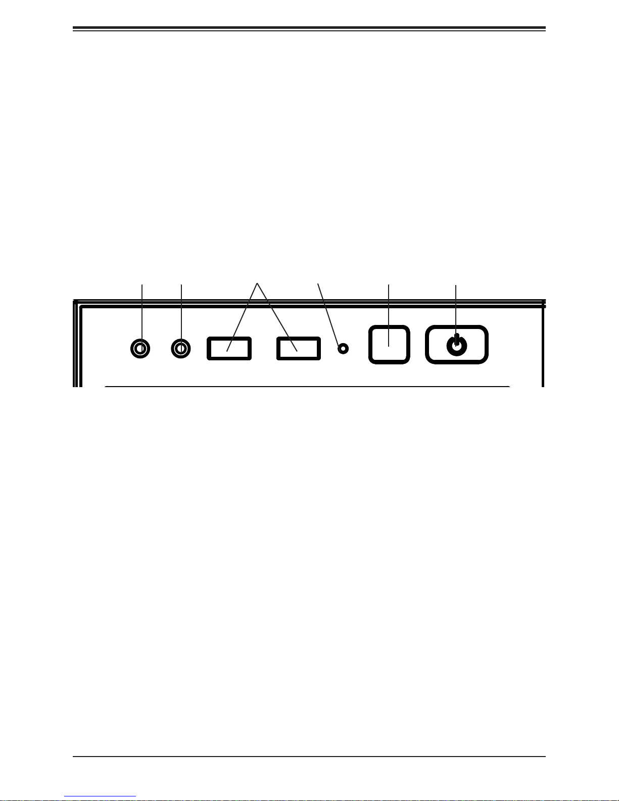
Control Panel
The 5130AD-T features a front panel allowing easy access to the system power and
communication ports. The in addition to the HDD Activity LED, the Power button and the
Reset button, the following ports are available on the front panel:
• Two USB 3.0 ports
• Audio port
• Mic Port
Audio
Port
Mic
Port
USB 3.0
Ports
HDD
Activity
Reset
Button
Figure 1-1. Control Panel View
Power
Button
10
Chapter 1: Introduction
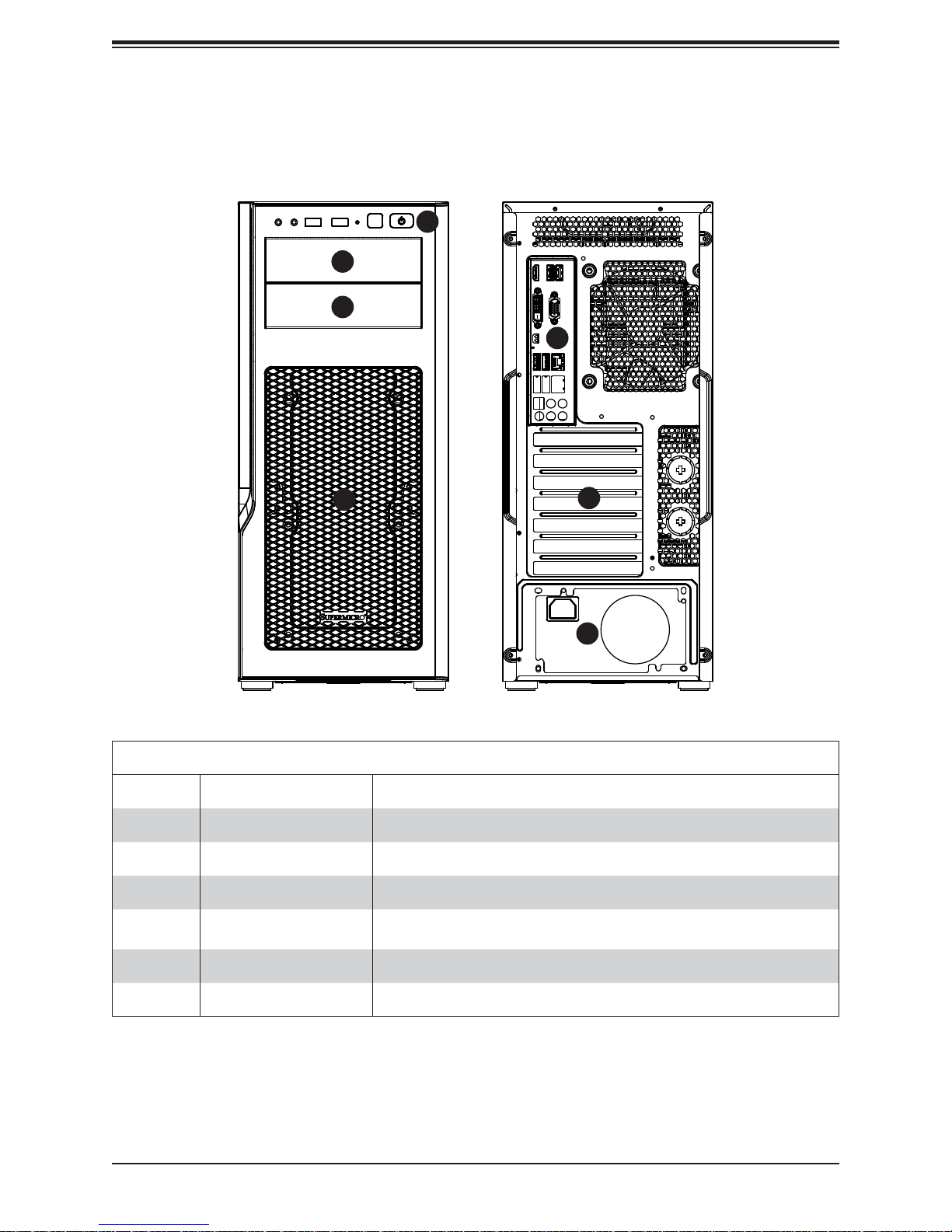
Front and Rear Features
The GS5A-753K is a mid-tower chassis See the illustrations below for the features included
on the front and rear of the chassis.
1
2
2
4
3
5
6
Figure 1-2. Chassis Front View
Front and Rear Chassis Features
Item Feature Description
1 Front Control Panel Front control panel as described in previous "Control Panel" section.
2 Front 5.25" Drive Bays Drive bays for 5.25" drives or optional devices
3 Front Bezel Screen Front grille with one click access to dust fi lter
4 Rear I/O ports
Rear I/O ports for system (shown as an example, your system I/O ports may
look different).
5 Expansion Cards Slots Openings for expansion cards
6 Power Supply The power supply and its power cord slot are accessed here.
11
System 5130AD-T User's Manual
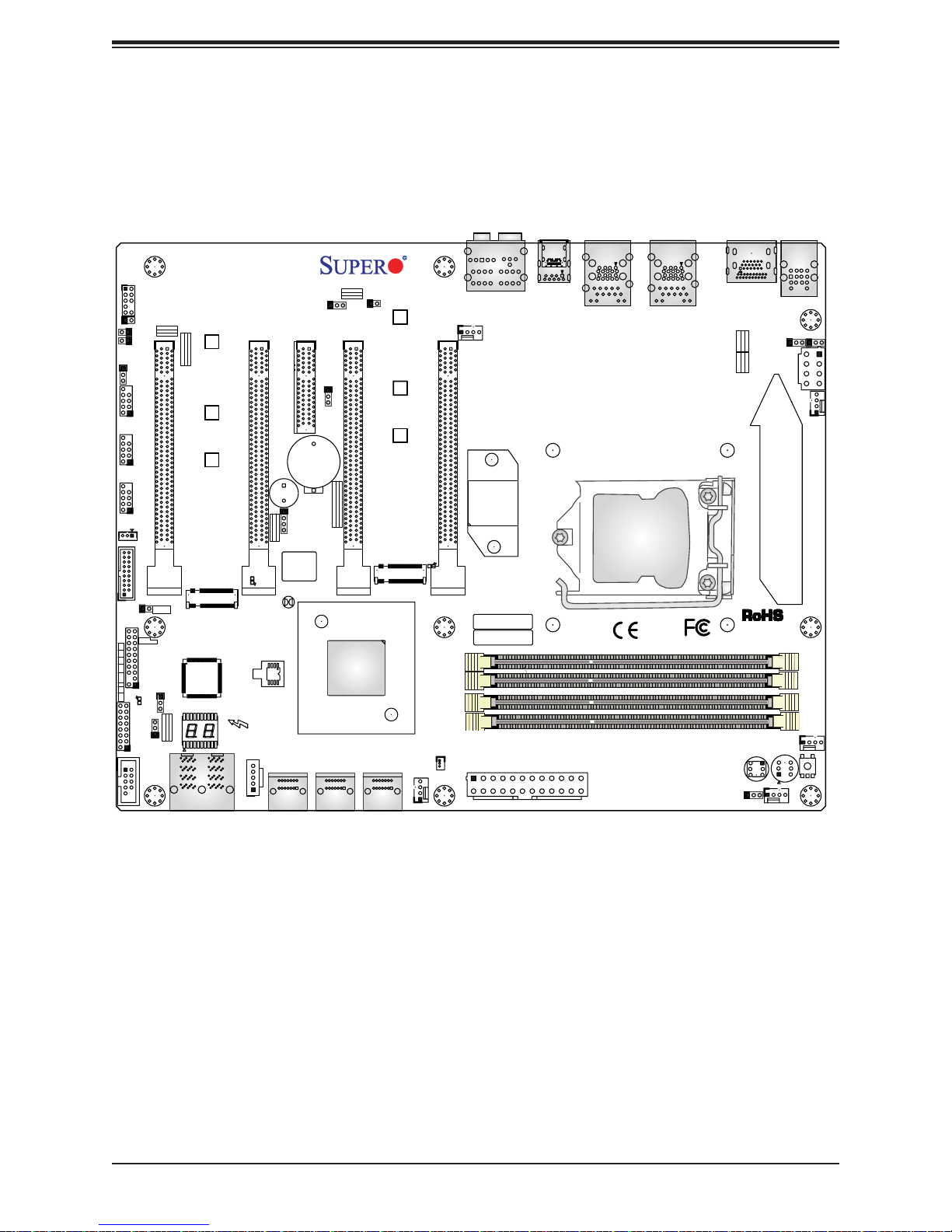
1.5 Motherboard Layout
Below is a layout of the C7Z270-PG with jumper, connector and LED locations shown. See
the table on the following page for descriptions. For detailed descriptions, pinout information
and jumper settings, refer to Chapter 4.
KB/MOUSE USB 0/1
JL1
JTPM1
LED
PWR
HDD
NIC
1LED
NIC
2
XOH/FF
RST
PWR
ON
JI2C2
JI2C1
JBR1
USB2/3
USB4/5
USB6/7
JLED1:
3 PIN POWER LED
JF1
AUDIO FP
JL2
JI2C1/JI2C2
ON :ENABLE
JBR1
ON:BIOS RECOVERY
OFF:NORMAL
OFF:DISABLE
CPU SLOT1 PCI-E 3.0 X8 (IN X16)
JSTBY1
USB 14/15 (3.0)
JL1:
CHASSIS
INTRUSION
PCIE M.2 CONNECTOR 1
JTPM1:
TPM/PORT80
JLED1
LED1
JWD1:
1-2:RST
2-3:NMI
WATCH DOG
JWD1
COM1
MH10
MH11
MH12
LED4
PRESS FIT
C7Z270-PG
PCH SLOT4 PCI-E 3.0 X4
CPU SLOT3 PCI-E 3.0 X16
SP1
BUZZER:3-4
JD1:
SPEAKER:1-4
JD1
BIOS LICENSE
LED3
A
C
JBT1
U6
U.2 CONNECTOR 2
U.2 CONNECTOR 1
I-SATA4
I-SATA5
JTBT
JPAC1
JPME2
B1
J*
I-S ATA2
I-S ATA3
JPAC1:AUDIO
1-2:ENABLE
JSPDIF_OUT
2-3:DISABLE
REV:1.00
DESIGNED IN USA
MH14
CPU SLOT5 PCI-E 3.0 X8 (IN X 16)
JPME2:
2-3:ME MANUFACTURING MODE
1-2:NORMAL
I-SATA0
I-SATA1
MH15
MH13
PCIE M.2 CONNECTOR 2
FAN3
SYS_FAN2
HD AUDIO
FAN5
CPU SLOT7 PCI-E 3.0 X16
SYS_FAN3
LED2
MAC CODE
BAR CODE
DIMMA1
DIMMA2
DIMMB1
DIMMB2
JSD1
JPW1
USB 12/13 (3.1)
USB 10/11(3.1)
LAN2
USB8/9(3.0)
CPU
LAN1
POWER BUTTON
JVR1
HDMI/DP
2-3:DISABLE
1-2:ENABLE
JPL1:LAN1
2-3:DISABLE
1-2:ENABLE
JPL2:LAN2
RESET BUTTON
S12
SYS_FAN1
FAN2
JPL2
JPW2
JPL1
FAN4
CPU_FAN2
CPU_FAN1
FAN1
S8
CLEAR CMOS
Figure 1-4. Motherboard Layout
12
Chapter 1: Introduction
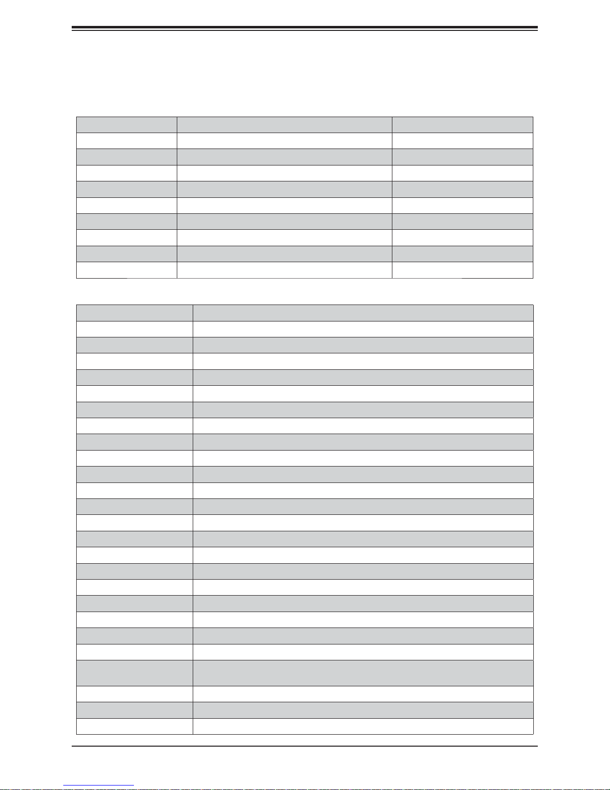
Quick Reference Table
Jumper Description Default Setting
CLEAR CMOS Clear CMOS Switch Push Button Switch
JBR1 BIOS Recovery Switch Pins 1-2 (Disable)
JBT1 Clear CMOS (on board) Short pads to clear CMOS
JI2C1/JI2C2 SMB to PCI Slots Open (Disable)
JPAC1 Audio Enable Pins 1-2 (Enabled)
JPL2 LAN3/LAN4 Enable/Disable Pins 1-2 (Enabled)
JPME2 Intel® Manufacturing Mode Pins 1-2 (Normal)
JWD1 Watch Dog Function Enable Pins 1-2 (RST)
POWER BUTTON Internal Power Button Push Button Switch
RESET BUTTON Onboard System Reset Button Push Button Switch
Connector Description
AUDIO FP Front Panel Audio Header
B1 Onboard Battery
COM1 COM1 Port Header
FANS 1-5 System/CPU Fan Headers (Fan 1, Fan 4: CPU Fans; Fan 2, Fan 3, Fan 5: System Fans)
HD Audio High Defi nition Audio Ports
HDMI/DP High Defi nition Multimedia Interface/Display Port
I-SATA0~5 (Intel® Z270) Serial ATA (SATA 3.0) Ports 0~5 (6Gb/sec)
JD1 Speaker/buzzer (Pins 1~4: External Speaker, Pins 3~4: Buzzer)
JF1 Front Control Panel Header
JL1 Chassis Intrusion Header
JLED1 Power LED Indicator Header
JPW1 24-pin ATX Main Power Connector (Required)
JPW2 +12V 8-pin CPU power Connector (Required)
JSD1 SATA DOM (Disk On Module) Power Connector
JSPDIF_OUT Sony/Philips Digital Interface Format (S/PDIF) Out Header
JSTBY1 Standby Power Header
JTBT Thunderbolt Connector
JTPM1 Trusted Platform Module (TPM) Header
KB/MOUSE PS2 Keyboard/Mouse Connectors
LAN1/LAN2 RJ45 Gigabit LAN Ports
MH 10-12 Mounting holes for PCI-E M.2 Connector 1
MH 13-15 Mounting holes for PCI-E M.2 Connector 2
PCI-E M.2 CONNECTOR 1, 2 PCI-E M.2 Connectors 1 and 2, small form factor devices and other portable devices for
High speed NVMe SSDs
Slot 1/7 CPU PCI-E 3.0 x16 Slots
Slot 3/5 CPU PCI-E 3.0 x8 (IN x16) Slots
Slot 4 PCH PCI-E 3.0 x4
13
System 5130AD-T User's Manual
SP1 Internal Speakers
U.2 CONN ECTOR 1, 2 U.2 Conne ctor 1 an d 2, for 2. 5” SS D Drive s
USB 0/1 Back Panel U SB 2.0 Po rt s
USB 2/ 3, USB 4 /5, USB 6 /7 Front Panel Acc ess ible US B 2.0 He aders
USB 8/9 Back Panel U SB 3.0 Por t s
USB 10/11, USB 12/13 Back Panel U SB 3.1 Ports
USB 14/15 Front Panel Accessible USB 3.0 Header
LED Description Color State Status
LED1 Onboard S tand by PWR LE D Green: Solid on Power On
LED2 M.2 connector 2 SSD ACT LED Green: Solid on M.2 device connected
LED3 M.2 connector 1 SSD ACT LED Green: Solid on M.2 device connected
LED4 Status Code LED* Digital Readout See manual
PCIe x 8 (in x16) SLOT #7
PCIe x 8 (in x16) SLOT #3
PCIe x16 SLOT #5
PCIe x 8 (in x16) SLOT #2
PCIe3.0_x8
8.0GT/s
PCIe3.0_x8
8.0GT/s
PCIe x16 SLOT #1
PCIe x 8 (in x16) SLOT #2
PCIe3.0_x8
8.0GT/s
PCIe3.0_x8
8.0GT/s
PCIe3.0_x8
or
ASMedia Switch
ASM1480
or
ASMedia Switch
ASM1480
1
2
3
4
1
2
3
4
8.0GT/s
PCIe3.0_x8
8.0GT/s
PCIe3.0_x8
8.0GT/s
PCIe3.0_x8
8.0GT/s
2 X USB 3.1 Rear Type-A
PLX8747
HDMI 2.0
Display Port
PCIe x4 SLOT #4
RJ45
GLAN2 I210
U.2 SOCKET SSD
ASM1142 USB3.1
2 X USB 3.0 Header
B
2 X USB 2.0 Rear
6 X USB 2.0 Header
Audio Jack/ Aduio Pin Header
PCIe3.0_x16
8.0GT/s
PS175
DDI2
DDI3
PCIe3.0_x4
8GT/s
PCIe3.0_x1
8GT/s
PCIe3.0_x4
8GT/s
PCIe3.0_x1
8GT/s
USB3.0
5Gbps
USB2.0
480Mbps
USB2.0
480Mbps
Realtek ALC1150
SVID
Intel
PCH-H
Z270
SPI 128Mb
x4 DMI
8GT/s
FLASH
IMVP8
SPI
INTEL LGA1151
DDI1
DDI 1
(Socket-H4)
DDI 2
DDI 3
AZALIA
AMPHead Phone Header
DDR4 (CHA)
2133/1866/1600MHz
DDR4 (CHB)
2133/1866/1600MHz
PCIe3.0_x1
8GT/s
PCIe3.0_x1
8GT/s
(SATA-III)
PCIe3.0_x2
8GT/s
PCIe3.0_x2
8GT/s
PCIe3.0_x4
8GT/s
SATA-III
6Gb/s
LPC
IMVP8
DIMMA0
DIMMA1
DIMMB0
DIMMB1
GLAN1
I219
ASM1142 USB3.1
ASMedia Switch
ASM1480
ASMedia Switch
ASM1480
TPM1.2 Header
NCT6792D-B
LPC I/O
RJ45
SATA-III
PCIe3.0_x2
4 X SATA-III
COM1 Header
PS2 KB/MS
1 X USB Type-A
ASM1543
6Gb/s
8GT/s
2 X SATA-III
1 X USB Type-C
M.2 SOCKET SSD
M.2 SOCKET SSD
U.2 SOCKET SSD
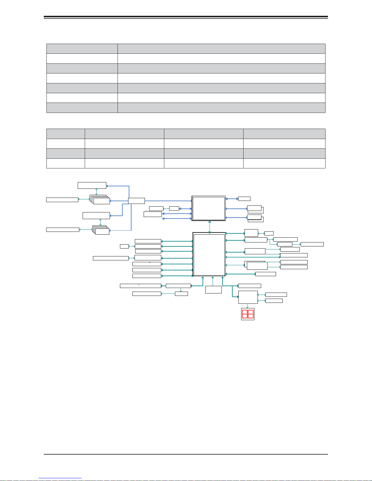
Figure 1-5. Intel Z270 Chipset: System Block Diagram
Note: This is a general block diagram and may not exactly represent the features on your
motherboard. See the System Specifi cations appendix for the actual specifi cations of your
motherboard.
14

Chapter 2: Server Installation
Chapter 2
Desktop Setup
2.1 Overview
This chapter provides a quick setup checklist to get your 5130AD-T up and running. Following
these steps in the order given should enable you to have the system operational within a
minimum amount of time. This quick setup assumes that your system has come to you with
the motherboard preinstalled.
2.2 Unpacking the System
You should inspect the box the system was shipped in and note if it was damaged in any
way. If the system itself shows damage you should fi le a damage claim with the carrier who
delivered it.
Decide on a suitable location for the system. It should be situated in a clean, dust-free area
that is well ventilated. Avoid areas where heat, electrical noise and electromagnetic fi elds are
generated. You will also need it plugged into a grounded power outlet. Be sure to read the
Warnings and Precautions in the next section.
2.3 Warnings and Precautions!
Review the electrical and general safety precautions in Chapter 4.
Use a regulating uninterruptible power supply (UPS) to protect the system from power surges,
voltage spikes and to keep your system operating in case of a power failure.
• Allow the power supply units to cool before touching them.
Workstations Precautions
• Ensure that the caster wheels on the desktop are locked.
• Review the electrical and general safety precautions in Chapter 4.
• Use a regulating uninterruptible power supply (UPS) to protect the desktop from power
surges, voltage spikes and to keep your system operating in case of a power failure.
• Allow the power supply units and hot-swap SATA drives to cool before touching them.
• To maintain proper cooling, always keep all chassis panels closed and all SATA carriers
installed when not being serviced.
15
System 5130AD-T User's Manual
2.4 Accessing the Inside of the System
Y ou may need to access the system periodically to perform maintenance or install components
such as hard drives. The system features two removable side covers, allowing easy access
to the system interior.
Caution: Except for short periods of time, do not operate the system without the cover in
place. The chassis cover must be in place to allow proper airfl ow.
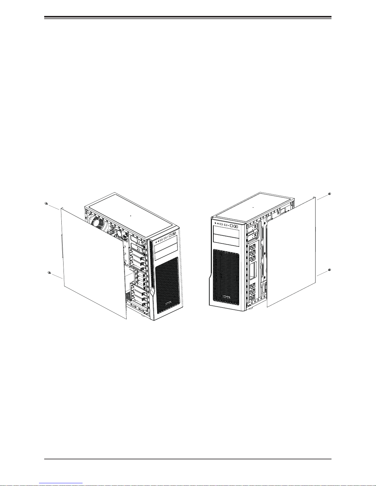
Left Side and Right Side Covers
Removing a Side Chassis Cover
1. Power down the system.
2. Remove the two thumb screws on the rear of the chassis.
3. Slide the cover back toward the rear of the chassis.
Figure 2-1. Removing the Chassis Side Covers
16
Chapter 2: Server Installation
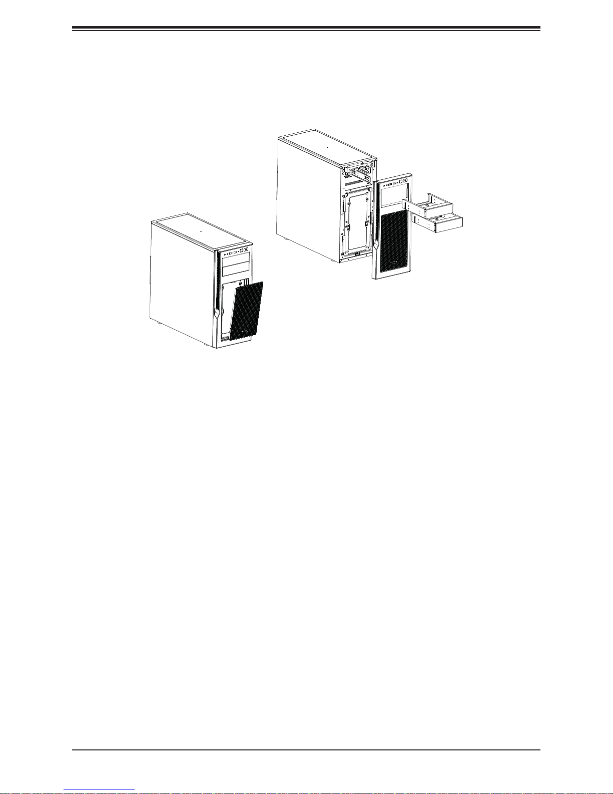
Front Bezel
Remove the front bezel by pulling it off from the bottom of the bezel. This should only be
necessary when replacing the front fans.
Figure 2-2. Removing the Front Bezel
17

System 5130AD-T User's Manual
Chapter 3
Maintenance and Component Installation
This chapter provides instructions on installing and replacing main system components. To
prevent compatibility issues, only use components that match the specifi cations and/or part
numbers given.
Installation or replacement of most components require that power fi rst be removed from the
system. Please follow the procedures given in each section.
3.1 Removing Power
Use the following procedure to ensure that power has been removed from the system. This
step is necessary when removing or installing non hot-swap components or when replacing
a non-redundant power supply.
1. Use the operating system to power down the system.
2. After the system has completely shut-down, disconnect the AC power cord(s) from the
power strip or outlet. (If your system has more than one power supply, remove the AC
power cords from all power supply modules.)
3. Disconnect the power cord(s) from the power supply module(s).
3.3 Motherboard Components
Processor and Heatsink Installation
Follow the procedures in this section to install a processor (CPU) and heatsink to the
motherboard.
Notes:
• The motherboard should be installed into the chassis fi rst and the processor should be
installed into the CPU socket before you install a CPU heatsink.
• If you bought a CPU separately, make sure that you use an Intel-certifi ed multi-directional
heatsink only.
• When receiving a motherboard without a processor pre-installed, make sure that the plastic
CPU socket cap is in place and none of the socket pins are bent; otherwise, contact your
retailer immediately.
• Refer to the Supermicro website for updates on CPU support.
18
Chapter 3: Maintenance and Component Installation
Installing the LGA1151 Processor
Begin by removing power from the system as described in Section 3.1.
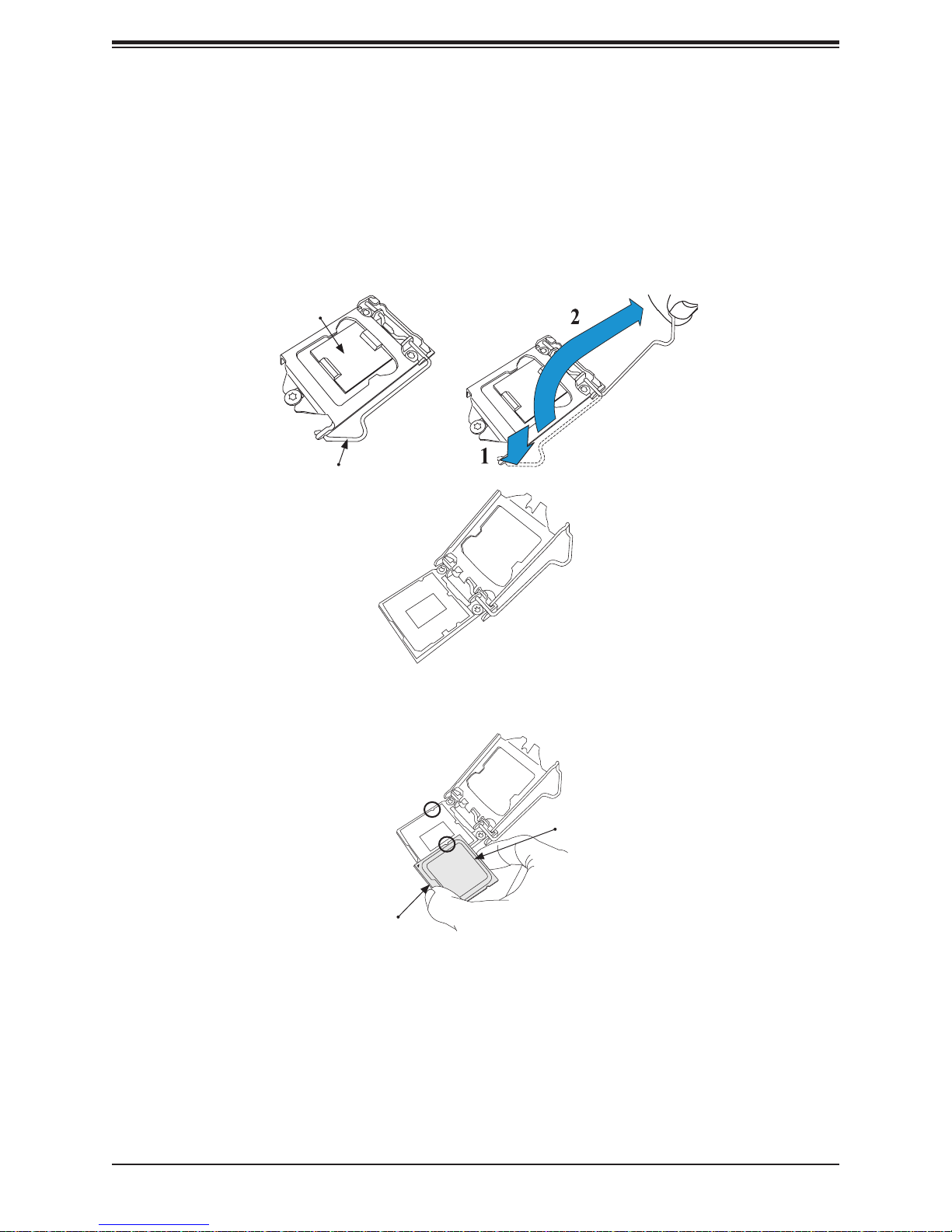
Installing a Processor
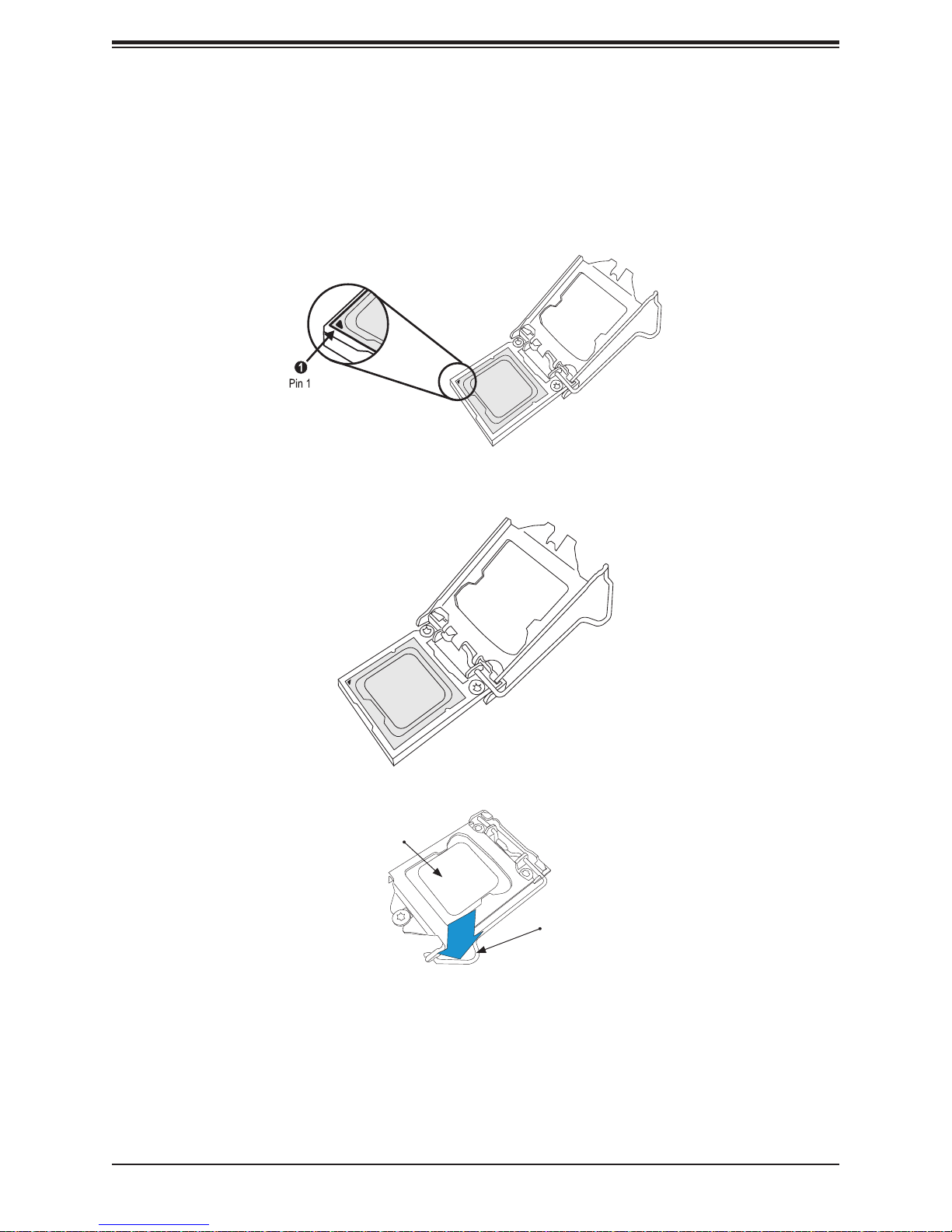
1. Press the load lever to release the load plate, which covers the CPU socket, from its
locking position.
2. Gently lift the load lever to open the load plate. Remove the plastic cap.
Load Plate
Load Lever
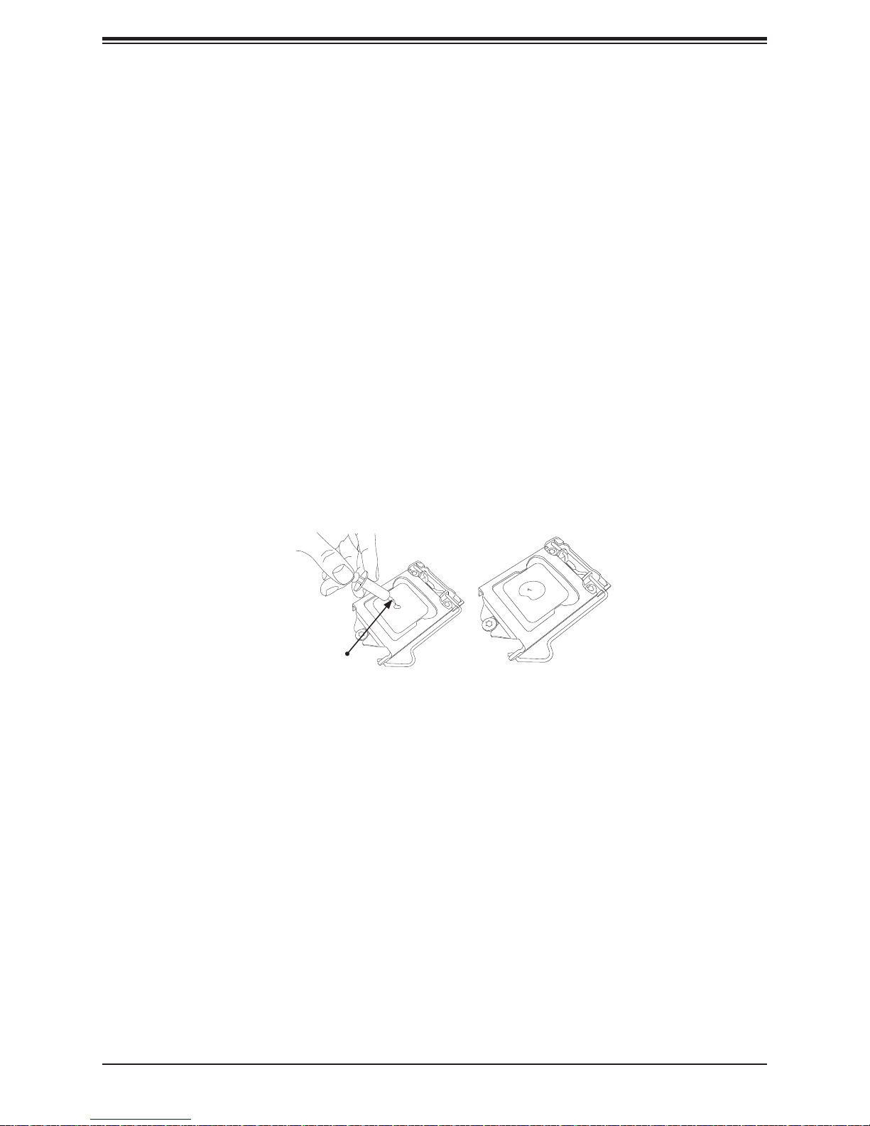
3. Use your thumb and your index fi nger to hold the CPU at the North center edge and the
South center edge of the CPU.
North Center Edge
South Center Edge
19
System 5130AD-T User's Manual
4. Align the CPU key that is the semi-circle cutouts against the socket keys. Once it is
aligned, carefully lower the CPU straight down into the socket.
Warning: Do not drop the CPU on the socket. Do not move the CPU horizontally or vertically.
Do not rub the CPU against the surface or against any pins of the socket in order to avoid
damaging the CPU or the socket.
5. With the CPU inside the socket, inspect the four corners of the CPU to make sure that
the CPU is properly installed.
6. Use your thumb to gently push the load lever down to the lever lock.
Attention! You can only install the CPU inside the socket only in one direction. Make sure
that it is properly inserted into the CPU socket before closing the load plate. If it doesn't close
properly, do not force it as it may damage your CPU. Instead, open the load plate again and
double-check that the CPU is aligned properly.
CPU properly
installed
Load lever locked
into place
20
Chapter 3: Maintenance and Component Installation
Installing a Heatsink
The use of active type heatsinks are recommended (except in 1U systems). To install a thirdparty heatsink, please follow the installation instructions included with the heatsink package.
Installing an Active CPU Heatsink with Fan
1. Locate the CPU Fan power connector on the motherboard. (Refer to the layout on the
right for the CPU Fan location.)
2. Position the heatsink so that the heatsink fan wires are closest to the CPU fan power
connector and are not interfered with other components.
3. Inspect the CPU Fan wires to make sure that the wires are routed through the bottom of
the heatsink.
4. Remove the thin layer of the protective fi lm from the heatsink.
Attention! CPU overheating may occur if the protective fi lm is not removed from the heatsink.
5. Apply the proper amount of thermal grease on the CPU.
Note: If your heatsink came with a thermal pad, please ignore this step.
Thermal Grease
6. If necessary, rearrange the wires to make sure that the wires are not pinched between
the heatsink and the CPU. Also make sure to keep clearance between the fan wires and
the fi ns of the heatsink.
21
System 5130AD-T User's Manual
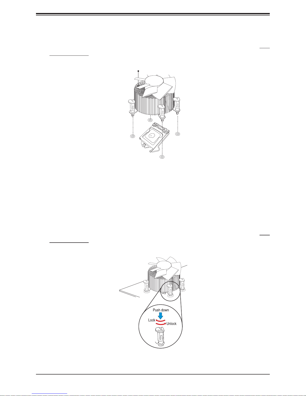
7. Align the four heatsink fasteners with the mounting holes on the motherboard. Gently
push the pairs of diagonal fasteners (#1 & #2, and #3 & #4) into the mounting holes until
you hear a click. Also, make sure to orient each fastener so that the narrow end of the
groove is pointing outward.
Heatsink Fins
8. Repeat Step 7 to insert all four heatsink fasteners into the mounting holes.
9. Once all four fasteners are securely inserted into the mounting holes, and the heatsink
is properly installed on the motherboard, connect the heatsink fan wires to the CPU Fan
connector.
Note: It is recommended that you use the Supermicro SNK-P0046A4 active heatsink for this
system.
10. Align the four heatsink fasteners with the mounting holes on the motherboard. Gently
push the pairs of diagonal fasteners (#1 & #2, and #3 & #4) into the mounting holes until
you hear a click. Also, make sure to orient each fastener so that the narrow end of the
groove is pointing outward.
11. Repeat Step 7 to insert all four heatsink fasteners into the mounting holes.
22
Chapter 3: Maintenance and Component Installation
12. Once all four fasteners are securely inserted into the mounting holes, and the heatsink
is properly installed on the motherboard, connect the heatsink fan wires to the CPU Fan
connector.
Removing the Heatsink
We do not recommend that the CPU or the heatsink be removed. However, if you do need
to remove the heatsink, please follow the instructions below to remove the heatsink and to
prevent damage done to the CPU or other components.
Active Heatsink Removal
1. Unplug the power cord from the power supply.
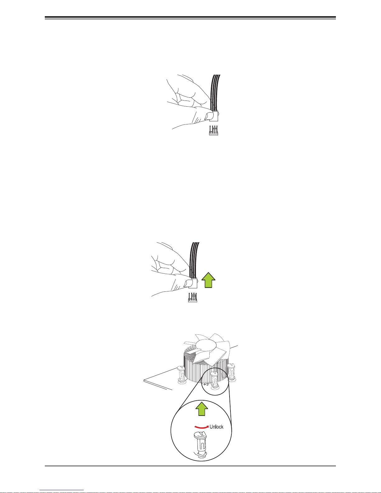
2. Disconnect the heatsink fan wires from the CPU fan header.
Unplug the
PWR cord
3. Use your fi nger tips to gently press on the fastener cap and turn it counterclockwise to
make a 1/4 (90
0
) turn, and pull the fastener upward to loosen it.
Pull Up
23
System 5130AD-T User's Manual
4. Repeat Step 3 to loosen all fasteners from the mounting holes.
5. With all fasteners loosened, remove the heatsink from the CPU.
Memory Installation
Memory Support
The C7Z270-PG supports up to 64 GB of unbuffered, non-ECC, 3600 MHz (OC) DDR4
memory in four (4) memory slots. Populating two adjacent slots at a time with memory
modules of the same size and type will result in interleaved (128-bit) memory, which is faster
than non-interleaved (64-bit) memory.
Check the Supermicro website for possible updates to memory support.
Installing Memory
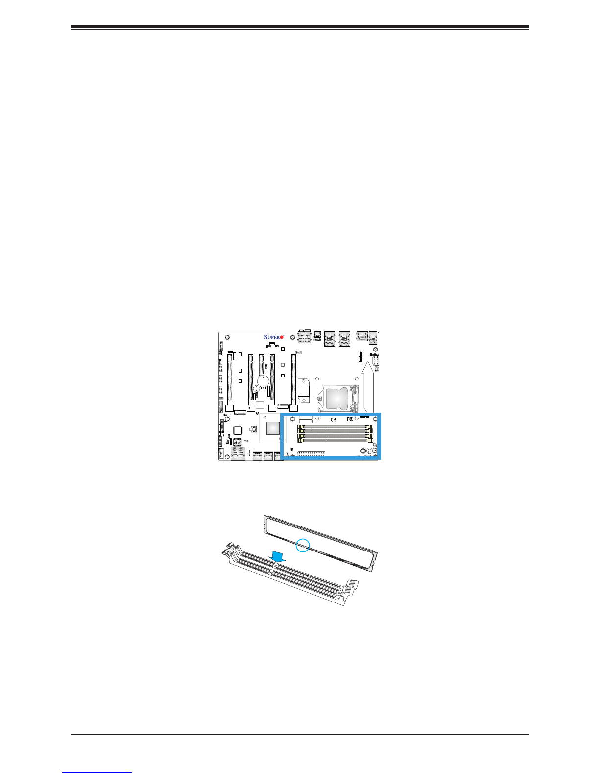
1. Insert the desired number of DIMMs into the memory slots, starting with DIMMA1 (see
the next page for the location). For the system to work properly, please use the memory
modules of the same type and speed in the same motherboard.
JVR1
HDMI/DP
2-3:DISABLE
1-2:ENABLE
JPL1:LAN1
2-3:DISABLE
1-2:ENABLE
JPL2:LAN2
RESET BUTTON
SYS_FAN1
KB/MOUSE USB 0/1
JPL2
JPL1
JPW2
FAN4
CPU_FAN2
CPU_FAN1
FAN1
S12
S8
CLEAR CMOS
FAN2
JL2
JI2C2
JI2C1
JBR1
USB2/3
USB4/5
USB6/7
JL1
JTPM1
LED
PWR
HDD
NIC
1LED
NIC
2
XOH/FF
RST
JLED1:
PWR
3 PIN POWER LED
ON
LED1
JF1
AUDIO FP
JI2C1/JI2C2
ON :ENABLE
OFF:DISABLE
CPU SLOT1 PCI-E 3.0 X8 (IN X16)
JSTBY1
USB 14/15 (3.0)
JL1:
CHASSIS
INTRUSION
JTPM1:
TPM/PORT80
JLED1
JWD1:
1-2:RST
2-3:NMI
WATCH DOG
JWD1
COM1
MH10
JBR1
ON:BIOS RECOVERY
OFF:NORMAL
MH11
MH12
PCIE M.2 CONNECTOR 1
LED4
PRESS FIT
C7Z270-PG
CPU SLOT3 PCI-E 3.0 X16
SP1
BUZZER:3-4
JD1:
SPEAKER:1-4
JD1
LED3
A
C
JBT1
U6
U.2 CONNECTOR 2
U.2 CONNECTOR 1
I-SATA4
I-SATA5
JTBT
JPAC1
DESIGNED IN USA
PCH SLOT4 PCI-E 3.0 X4
JPME2
2-3:ME MANUFACTURING MODE
B1
BIOS LICENSE
J*
I-SATA2
I-SATA3
JPAC1:AUDIO
1-2:ENABLE
JSPDIF_OUT
2-3:DISABLE
REV:1.00
CPU SLOT5 PCI-E 3.0 X8 (IN X 16)
JPME2:
1-2:NORMAL
I-SATA0
I-SATA1
MH14
MH15
PCIE M.2 CONNECTOR 2
SYS_FAN2
MH13
FAN3
HD AUDIO
FAN5
CPU SLOT7 PCI-E 3.0 X16
LED2
DIMMA1
DIMMA2
DIMMB1
DIMMB2
JSD1
JPW1
SYS_FAN3
MAC CODE
BAR CODE
USB 12/13 (3.1)
USB 10/11(3.1)
USB8/9(3.0)
LAN1
LAN2
CPU
POWER BUTTON
2. Push the release tabs outwards on both ends of the DIMM slot to unlock it.
3. Align the key of the DIMM module with the receptive point on the memory slot.
24
Chapter 3: Maintenance and Component Installation
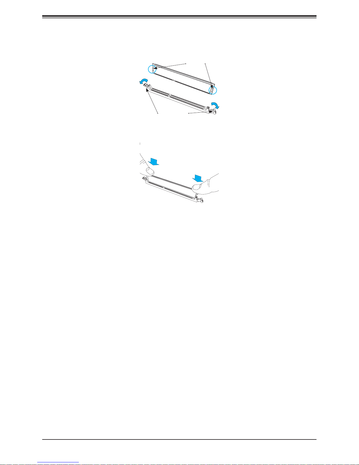
4. Align the notches on both ends of the module against the receptive points on the ends
of the slot.
Notches
Release Tabs
5. Use two thumbs together to press the notches on both ends of the module straight down
into the slot until the module snaps into place.
Press both notches
straight down into
the memory slot.
6. Press the release tabs to the lock positions to secure the DIMM module into the slot.
Removing Memory Modules
Reverse the steps above to remove the DIMM modules from the motherboard.
Caution: Exercise extreme caution when installing or removing memory modules to prevent
any possible damage to the DIMMs or slots.
Warning: In dual-CPU confi gurations, memory must be installed in the DIMM slots associated
with the installed CPUs.
Note: Visit the product page on the Supermicro website for possible updates to memory
support (
www.supermicro.com).
25
System 5130AD-T User's Manual
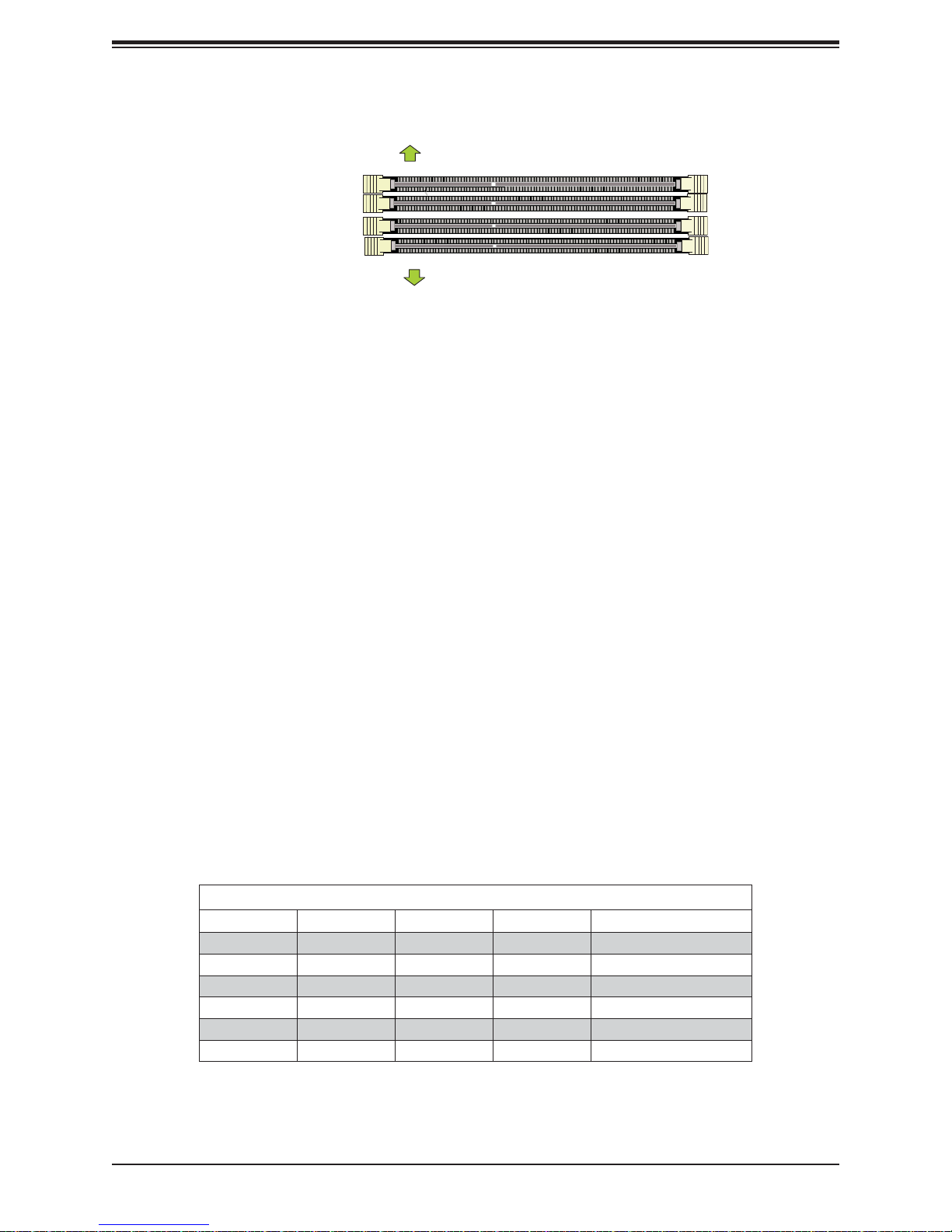
Memory Support
Towards the CPU
DIMMA1 (Black Slot)
DIMMA2 (Gray Slot)
DIMMB1 (Black Slot)
DIMMB2 (Gray Slot)
Towards the edge of the motherboard
The C7Z270-PG supports up to 64 GB of Unbuffered (UDIMM) non-ECC DDR4 memory, up
to 3600 MHz (OC) in four 288-pin memor y slots. Populating these DIMM modules with a pair
of memory modules of the same type and same size will result in interleaved memory, which
will improve memory performanc e.
Notes:
Be sure to use memory modules of the same type, same speed, same frequency on the
same motherboard. Mixing of memory modules of different types and speeds is not allowed.
Due to memory allocation to system devices, the amount of memory that remains available
for operational use will be reduced when 4 GB of RAM is used. The reduction in memory
availability is disproportional. See the following table for details.
For Microsoft Windows users: Microsoft implemented a design change in the Windows XP with
Service Pack 2 (SP2) and Windows Vista. This change is specifi c to the behavior of Physical
Address Extension (PAE) mode which improves driver compatibility. For more information,
please read the following article at
Microsoft’s Knowledge Base website at:
http://support.microsoft.com/kb/888137.
Memory Population Guidelines
When installing memory modules, the DIMM slots should be populated in the following order:
DIMMA1, DIMMB1, then DIMMA2, DIMMB2. Always use DDR4 DIMM modules of the same
size, type and speed. Mixed DIMM speeds can be installed. However, all DIMMs will run at
the speed of the slowest DIMM.
Recommended Population (Balanced)
DIMMA1 DIMMB1 DIMMA2 DIMMB2 Total System Memory
4GB 4GB 8GB
4GB 4GB 4GB 4GB 16GB
8GB 8GB 16GB
8GB 8GB 8GB 8GB 32GB
16GB 16GB 32GB
16GB 16GB 16GB 16GB 64GB
26

Chapter 3: Maintenance and Component Installation
PCI Expansion Card Installation
Installing Expansion Cards
Installing an Expansion Card
1. Power down the system as described in section 6-2 and open the left side chassis
cover.
2. Remove the blank PCI shield from the rear of the chassis by removing the thumb screw.
3. Insert the expansion card into the motherboard expansion slot while aligning the
expansion card bracket with the opening in the rear of the chassis.
4. Secure the expansion card bracket to the rear of the chassis with the thumb screw.
5. Replace the chassis side cover and power up the system.
27
System 5130AD-T User's Manual
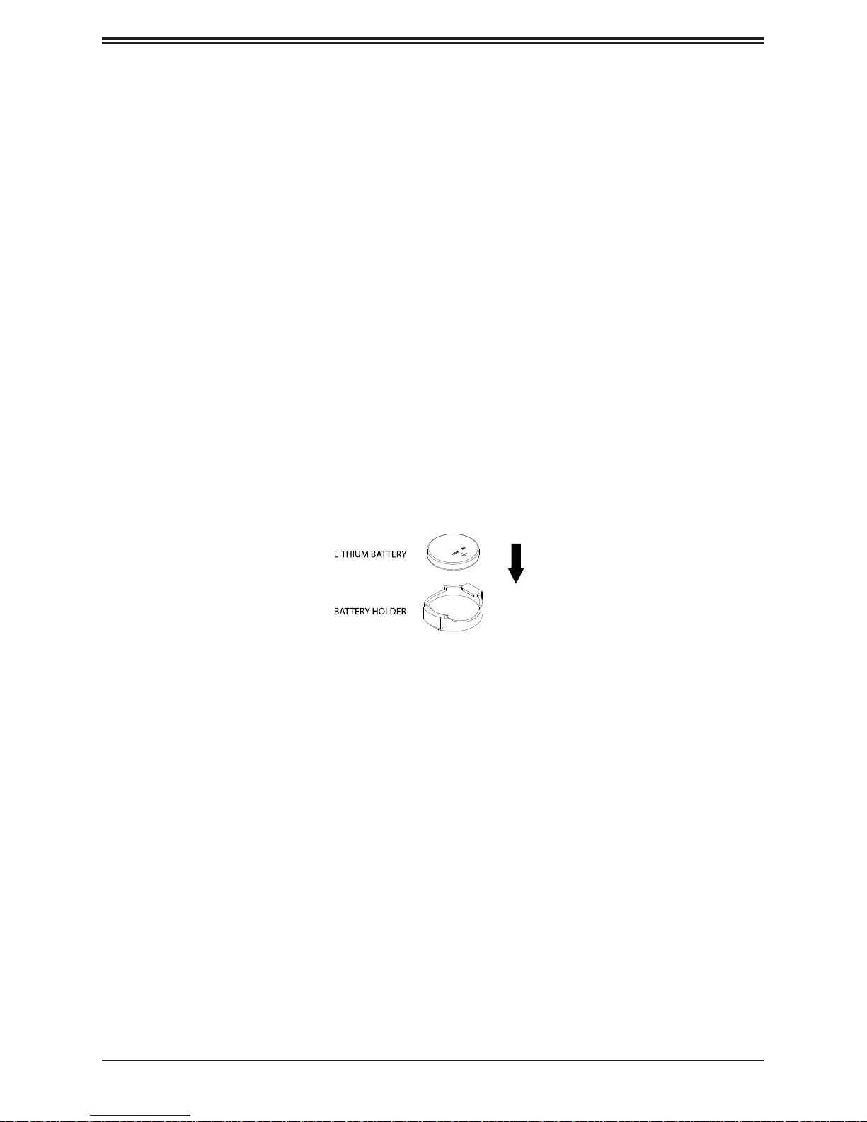
Motherboard Battery
The motherboard uses non-volatile memory to retain system information when system power
is removed. This memory is powered by a lithium battery residing on the motherboard.
Replacing the Battery
Begin by removing power from the system as described in section 3.1.
1. Push aside the small clamp that covers the edge of the battery. When the battery is
released, lift it out of the holder.
2. To insert a new battery, slide one edge under the lip of the holder with the positive (+)
side facing up. Then push the other side down until the clamp snaps over it.
Note: Handle used batteries carefully. Do not damage the battery in any way; a damaged
battery may release hazardous materials into the environment. Do not discard a used battery
in the garbage or a public landfi ll. Please comply with the regulations set up by your local
hazardous waste management agency to dispose of your used battery properly.
Warning: There is a danger of explosion if the onboard battery is installed upside down (which
reverses its polarities). This battery must be replaced only with the same or an equivalent type
recommended by the manufacturer (CR2032).
Figure 3-1. Installing the Onboard Battery
28

Chapter 3: Maintenance and Component Installation
3.4 Chassis Components
Supermicro S5 SI Edition Titanium Black chassis (GS5A-753K) blends elegance and fl exibility
into a refi ned home for your high-performance hardware.
Key Features
• Black anodized brushed aluminum fascia front panel with two USB 3.0 ports
• Removable 3.5” and 2.5” HDD/SSD cages with tool-less trays for up to 10 drives
• Tool-less 5.25” device installation with trays to support 3.5” and 2.5” drives additionally
• Cable management holes with rubber grommets for clean builds
• Removable magnetic dust fi lters
• One click front grille access
• Large motherboard tray cut-out for better CPU cooling
29
System 5130AD-T User's Manual
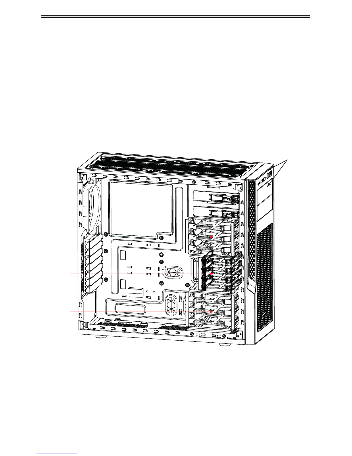
Hard Drives
The standard confi guration includes two 5.25" drive bays, four 2.5" drive bays, and six
combination bays that can house either 3.5" or 2.5" drives.
• Each 5.25" bay can be confi gured to accept a removable media drive, such as DVD, or a
storage device, such as a 3.5" HDD, 2.5" HDD, or solid state drive.
• The four 2.5" bays are housed in a removable cage.
• Two additional removable cages can each accommodate three 2.5" or 3.5" drives.
The SAS/SATA drives are mounted in drive carriers to simplify their installation and removal
from the chassis. (Both procedures may be done without removing power from the system.)
5.25' Bays
Combo Cage
for Three
Drives
Cage for
Four 2.5"
Drives
Combo Cage
for Three
Drives
Figure 3-2. Drive Bays
30
 Loading...