

Supermicro 5038K-i User Manual
5038K-i
User's Manual
Revision 1.0

The information in this User’s Manual has been carefully reviewed and is believed to be accurate.
The vendor assumes no responsibility for any inaccuracies that may be contained in this document,
makes no commitment to update or to keep current the information in this manual, or to notify any
person or organization of the updates. Please Note: For the most up-to-date version of this
manual, please see our web site at
www.supermicro.com.
Super Micro Computer, Inc. ("Supermicro") reserves the right to make changes to the product
described in this manual at any time and without notice. This product, including software and
documentation, is the property of Supermicro and/or its licensors, and is supplied only under a
license. Any use or reproduction of this product is not allowed, except as expressly permitted by
the terms of said license.
IN NO EVENT WILL SUPERMICRO BE LIABLE FOR DIRECT, INDIRECT, SPECIAL, INCIDENTAL,
SPECULATIVE OR CONSEQUENTIAL DAMAGES ARISING FROM THE USE OR INABILITY TO
USE THIS PRODUCT OR DOCUMENTATION, EVEN IF ADVISED OF THE POSSIBILITY OF
SUCH DAMAGES. IN PARTICULAR, SUPERMICRO SHALL NOT HAVE LIABILITY FOR ANY
HARDWARE, SOFTW ARE, OR DA TA STORED OR USED WITH THE PRODUCT, INCLUDING THE
COSTS OF REPAIRING, REPLACING, INTEGRATING, INSTALLING OR RECOVERING SUCH
HARDWARE, SOFTWARE, OR DATA.
Any disputes arising between manufacturer and customer shall be governed by the laws of Santa
Clara County in the State of California, USA. The State of California, County of Santa Clara shall
be the exclusive venue for the resolution of any such disputes. Super Micro's total liability for all
claims will not exceed the price paid for the hardware product.
FCC Statement: This equipment has been tested and found to comply with the limits for a class B
digital device, pursuant to Part 15 of the FCC Rules. These limits are designed to provide reasonable
protection against harmful interference in a residential installation. This equipment generates,
uses, and can radiate radio frequency energy and, if not installed and used in accordance with
the instructions, may cause harmful interference to radio communications. However, there is no
guarantee that interference will not occur in a particular installation. If this equipment does cause
harmful interference to radio or television reception, which can be determined by turning the
equipment off and on, the user is encouraged to try to correct the interference by one or more of
the following measures:
• Reorient or relocate the receiving antenna.
• Increase the separation between the equipment and receiver.
• Connect the equipment to an outlet on a circuit different from that to which the receiver
is connected.
• Consult the authorized dealer or an experienced radio/TV technician for help.
California Best Management Practices Regulations for Perchlorate Materials: This Perchlorate
warning applies only to products containing CR (Manganese Dioxide) Lithium coin cells. “Perchlorate
Material-special handling may apply. See
www.dtsc.ca.gov/hazardouswaste/perchlorate”
WARNING: Handling of lead solder materials used in this
product may expose you to lead, a chemical known to
the State of California to cause birth defects and other
reproductive harm.
Manual Revision 1.0
Release Date: June 03, 2016
Unless you request and receive written permission from Super Micro Computer, Inc., you may not
copy any part of this document.
Information in this document is subject to change without notice. Other products and companies
referred to herein are trademarks or registered trademarks of their respective companies or mark
holders.
Copyright © 2016 by Super Micro Computer, Inc.
All rights reserved.
Printed in the United States of America

iii
Preface
Preface
About This Manual
This manual is written for professional system integrators and PC technicians. It
provides information for the installation and use of the 5038K-i. Installation and
maintenance should be performed by experienced technicians only.
The 5038K-i is a high-end system based on the GS5A-753B mid-tower chassis and
the K1SPE motherboard.
Manual Organization
Chapter 1: Introduction
The fi rst chapter provides a checklist of the main components included with the
system and describes the main features of the K1SPE motherboard and the
GS5A-753B chassis.
Chapter 2: System Installation
This chapter describes the steps necessary to setup the 5038K-i and check out the
system confi guration prior to powering up the system.
Chapter 3: System Interface
Refer here for details on the system interface, which includes the functions and
information provided by the control panel on the chassis as well as other LEDs
located throughout the system.
Chapter 4: System Safety
Y ou should thoroughly familiarize yourself with this chapter for a general overview of
safety precautions that should be followed when installing and servicing the 5038K-i.
Chapter 5: Advanced Motherboard Setup
Chapter 5 provides detailed information on the K1SPE motherboard, including the
locations and functions of connections, headers and jumpers. Refer to this chapter
when adding or removing main memory and when reconfi guring the motherboard.
Chapter 6: Advanced Chassis Setup
Refer to Chapter 6 for detailed information on the GS5A-753B chassis. You should
follow the procedures given in this chapter when installing, removing or reconfi guring
SATA or peripheral drives.

5038K-i User's Manual
iv
Chapter 7: BIOS
The BIOS chapter includes an introduction to BIOS and provides detailed information
on running the CMOS Setup Utility.
Appendix A: BIOS Error Beep Codes
Appendix B: System Specifi cations

v
Preface
Notes

vi
5038K-i User's Manual
Table of Contents
Chapter 1 Introduction
1-1 Overview .........................................................................................................1-1
1-2 Motherboard Features .....................................................................................1-2
Processors ......................................................................................................1-2
Memory ...........................................................................................................1-2
SATA ..............................................................................................................1-2
PCI Expansion Slots ....................................................................................... 1-3
Onboard Controllers/Ports ..............................................................................1-3
Other Features ................................................................................................ 1-3
Recovery from AC Power Loss ....................................................................... 1-4
PC Health Monitoring ......................................................................................1-4
Fan Status Monitor with Firmware Control ...............................................1-4
Environmental Temperature Control ...........................................................1-4
System Resource Alert ............................................................................... 1-5
ACPI Features ................................................................................................. 1-5
Slow Blinking LED for Suspend-State Indicator ............................................. 1-5
Power Supply .................................................................................................. 1-5
Super I/O .........................................................................................................1-6
1-3 Chassis Features ............................................................................................1-6
Key Features ...................................................................................................1-6
System Power ................................................................................................. 1-6
Hard Drives .....................................................................................................1-7
Front Control Panel .........................................................................................1-7
Fans and Cooling ............................................................................................1-7
1-4 Contacting Supermicro ....................................................................................1-9
Chapter 2 Installation
2-1 Overview .........................................................................................................2-1
2-2 Unpacking the System .................................................................................... 2-1
2-3 Warnings and Precautions! ............................................................................. 2-1
2-3 Accessing the Inside of the System................................................................2-2
Left Side and Right Side Covers .................................................................... 2-2
Front Bezel ......................................................................................................2-3

vii
Table of Contents
Chapter 3 System Interface
3-1 Overview .........................................................................................................3-1
3-2 Control Panel Button .......................................................................................3-1
Power ..............................................................................................................3-1
Reset ...............................................................................................................3-1
3-3 Front Panel Components ................................................................................3-2
Chapter 4 Standardized Warning Statements for AC Systems
4-1 About Standardized Warning Statements .......................................................4-1
Warning Defi nition ...........................................................................................4-1
Installation Instructions .................................................................................... 4-4
Circuit Breaker ................................................................................................ 4-5
Power Disconnection Warning ........................................................................ 4-6
Equipment Installation .....................................................................................4-8
Restricted Area ................................................................................................4-9
Battery Handling ............................................................................................ 4-10
Redundant Power Supplies ..........................................................................4-12
Backplane Voltage ........................................................................................ 4-13
Comply with Local and National Electrical Codes ........................................ 4-14
Product Disposal ........................................................................................... 4-15
Hot Swap Fan Warning ................................................................................. 4-16
Power Cable and AC Adapter ......................................................................4-18
Chapter 5 Advanced Motherboard Setup
5-1 Handling the Motherboard ..............................................................................5-1
Precautions .....................................................................................................5-1
5-2 Connecting Cables .......................................................................................... 5-2
Connecting Data Cables ................................................................................. 5-2
Connecting Power Cables ..............................................................................5-2
Connecting the Control Panel ......................................................................... 5-2
5-3 I/O Ports ..........................................................................................................5-3
5-4 Installing Memory Modules ............................................................................. 5-4
DIMM Installation ............................................................................................ 5-4
Removing Memory Modules ........................................................................... 5-5
Memory Support .............................................................................................. 5-5
5-5 Motherboard Details ........................................................................................ 5-6
5-6 Connector Defi nitions ......................................................................................5-9
5-7 Jumper Settings ............................................................................................5-16
5-8 Onboard Indicators ........................................................................................5-19
5-9 SATA 3.0 Connections .................................................................................. 5-21

viii
5038K-i User's Manual
5-10 Installing Drivers ............................................................................................5-22
SuperDoctor 5 ............................................................................................... 5-23
5-11 Motherboard Battery .....................................................................................5-24
Chapter 6 Advanced Chassis Setup
6-1 Static-Sensitive Devices ..................................................................................6-1
Precautions .....................................................................................................6-1
6-2 Removing Power from the System .................................................................6-2
6-3 Accessing the Inside of the System................................................................6-2
Left Side and Right Side Covers .................................................................... 6-3
Front Bezel ......................................................................................................6-3
6-4 Installing Drives ............................................................................................... 6-4
6-5 Fans and Cooling ............................................................................................6-8
Water Cooled Heat Sink ................................................................................. 6-9
Air Flow .........................................................................................................6-10
Dust Filters .................................................................................................... 6-10
6-7 Installing Expansion Cards ............................................................................6-11
6-8 Power Supply .................................................................................................6-11
Chapter 7 BIOS
7-1 Introduction ...................................................................................................... 7-1
Starting BIOS Setup Utility .............................................................................. 7-1
How To Change the Confi guration Data .........................................................7-1
How to Start the Setup Utility .........................................................................7-2
7-2 Main Setup ...................................................................................................... 7-2
7-3 Advanced Setup Confi gurations......................................................................7-4
7-4 Event Logs ....................................................................................................7-46
7-5 IPMI ............................................................................................................... 7-48
7-6 Security Settings ...........................................................................................7-50
7-7 Boot Settings ................................................................................................. 7-53
Use this feature to confi gure Boot Settings: ............................................................ 7-53
7-8 Save & Exit ................................................................................................... 7-55
Appendix A BIOS Error Beep Codes
Appendix B System Specifi cations
C-1 Overview to UEFI BIOS ..................................................................................C-1
C-2 Recovering the UEFI BIOS Image (Main BIOS Block) ................................... C-1
C-3 Recovering the UEFI BIOS with a USB Device ............................................. C-1

Chapter 1
Introduction
1-1 Overview
The 5038K-i is a high-end workstation comprised of two main subsystems: the
GS5A-753B mid-tower chassis and the K1SPE single Intel® processor motherboard.
Please refer to our web site for information on operating systems that have been
certifi ed for use with the 5038K-i (www.supermicro.com).
These units are sold as complete systems with the motherboard, processor, and
heat sink assembly factory installed. These components are not user serviceable,
and the user should not attempt to remove or modify these components other than
adjustments specifi cally outlined in this manual. Making other adjustments to these
components risks damaging the system and voiding the system warranty.
If you believe there is a hardware problem with one of these components, please
contact Supermicro’s technical support team or your service contact if you have
purchased a service package for this system.
In addition to the motherboard and chassis, various hardware components have
been included with the 5038K-i, as listed below:
• One (1) rear exhaust fan, two (2) front cooling fans, two (2) top exhaust fans at
the top under the radiator for the liquid cooling unit
• Two (2) chassis 3.5" HDD cages (MCP-220-GS504-0N)
• One (1) chassis 2.5" HDD cage (MCP-220-GS505-0N)
Note: For your system to work properly, please follow the links below to download
all necessary drivers/utilities and the user’s manual for your system.
• Supermicro product manuals: http://www.supermicro.com/support/manuals/
• Product drivers and utilities: ftp://ftp.supermicro.com
• Product safety information:
http://www.supermicro.com/about/policies/safety_information.cfm
• If you have any questions, please contact our support team at:
support@supermicro.com
Chapter 1: Introduction
1-1

5038K-i User's Manual
1-2
1-2 Motherboard Features
At the heart of the 5038K-i lies the K1SPE, a single processor motherboard based
on the Intel® PCH C612 chipset. Below are the main features of the K1SPE. (See
Figure 1-1 for a block diagram of the chipset).
Processors
The K1SPE motherboard supports a single non-fabric Intel® Xeon Phi™ x200
processor in an Intel® LGA 3647 (P0) socket. With the Intel® C612 chipset, the
K1SPE. motherboard offers substantial system performance and storage capability.
Please refer to our website (http://www.supermicro.com/products/) for processor and
memory support updates.”
Other chipset features include:
• Direct Media Interface (up 10 Gb/s transfer, Full Duplex)
• Intel® Matrix Storage Technology and Intel Rapid Storage Technology
• Dual NAND Interface
• Intel I/O Virtualization (VT-d) Support
• Intel Trusted Execution Technology Support
• PCI Express 3.0 Interface (up to 8 GT/s)
• SATA Controller (up to 6Gb/sec)
• Advanced Host Controller Interface (AHCI)
Memory
The K1SPE has six (6) DIMM slots that can support 384 GB of Registered RDIMM
up to 64 GB size and DDR4 2400 MHz speed, 1.20V SDRAM. See Chapter 5 for
details.
SATA
A SATA controller is integrated into the chipset to provide a SATA3 subsystem
that supports seven (7) SATA 3.0 connections (I-SATA connectors 1-3, S-SATA
connectors 1-4). This system supports RAID 0, 1 and 10 (from the Intel PCH).
Additionally, two SATA DOM (Device-On-Module) power connectors (JSD1/2) are
provided.

1-3
Chapter 1: Introduction
PCI Expansion Slots
The K1SPE has the following available expansion ports on the motherboard:
• Two (2) PCI Express 3.0 x16 slots (CPU Slot4/Slot6)
• One (1) PCI Express 2.0 x4 (in x8) slot (PCH Slot2)
Onboard Controllers/Ports
Both the motherboard and chassis include the following I/O ports:
• Four (4) USB 3.0/2.0 ports on the rear I/O panel (USB 2.0 0/1, USB 2.0 5/6 or
USB 3.0 2/3, USB 3.0 7/8)
• One (1) Onboard USB header with two USB 3.0 connections (USB 3.0 8/9) for
front control panel
• One Intel i350 Gigabit (10/100/1000 Mb/s) Ethernet controller for a Gigabit
(GbE) LAN port
• One (1) Serial port on the IO back panel (COM1)
• One (1) Fast UART 16550 connection header (COM2)
• VGA port on the IO back panel
• One (1) TPM header
Other Features
Other onboard features of the motherboard include:
• BIOS features such as DMI 2.3, PCI 3.0, ACPI 3.0/4.0, USB Keyboard, Plug
& Play (PnP), BIOS Rescue hot-key, Real Time Clock (RTC), UEFI 2.3.1, and
SMBIOS 2.7 or later,
• CPU 6-Phase switching voltage regulator
• CPU/System overheat LED and control
• CPU Thermal Trip support
• Thermal Monitor 2 (TM2) support
• PECI (Platform Environment Confi guration Interface) 2.0 support
• Fan status monitoring with fi rmware 4-pin fan speed control
• Low noise fan speed control
• ACPI Power Management
• Power-on mode for AC power recovery
• Intel
®
Intelligent Power Node Manager (available when the NMView utility is
installed)
• Management Engine
• Riser card auto-detection

5038K-i User's Manual
1-4
• LED Indicators for: CPU/system overheat LED, Power/suspend state indicator,
Fan failure LED, LAN activity LED, BMC (BaseBoard Management) LED and
UID/Remote UID LED
• System resource alert via SuperDoctor® 5
• SuperDoctor® 5, Watch Dog, NMI, SPM, SUM-InBand, SUM-OOB
Recovery from AC Power Loss
Basic I/O System (BIOS) provides a setting for you to determine how the system will
respond when AC power is lost and then restored to the system. You can choose
for the system to remain powered off, (in which case you must press the power
switch to turn it back on), or for it to automatically return to a power-on state. See
the Advanced BIOS Setup section to change this setting. The default setting is
Last State.
PC Health Monitoring
This section describes the PC health monitoring features of the board. All have an
onboard System Hardware Monitoring chip that supports PC health monitoring. An
onboard voltage monitor will scan these onboard voltages continuously: CPU core,
+12V , +3.3V , 3.3V Standby , +5V , 5V Standby ,, VBA T, HT , Memory PCH T emperature,
System Temperature, and CPU Temperature. Once a voltage becomes unstable,
a warning is given, or an error message is sent to the screen. The user can adjust
the voltage thresholds to defi ne the sensitivity of the voltage monitor.
Fan Status Monitor with Firmware Control
PC health monitoring in the BIOS can check the RPM status of the cooling fans.
The onboard CPU and chassis fans are controlled by Thermal Management via SIO.
Environmental Temperature Control
The thermal control sensor monitors the CPU temperature in real time and will turn
on the thermal control fan whenever the CPU temperature exceeds a user-defi ned
threshold. The overheat circuitry runs independently from the CPU. Once the
thermal sensor detects that the CPU temperature is too high, it will automatically
turn on the thermal fans to prevent the CPU from overheating. The onboard chassis
thermal circuitry can monitor the overall system temperature and alert the user when
the chassis temperature is too high.
Note: To avoid possible system overheating, please be sure to provide adequate
airfl ow to your system.

1-5
Chapter 1: Introduction
System Resource Alert
This feature is available when the system is used with SuperDoctor 5 in the Windows
OS environment. SuperDoctor is used to notify the user of certain system events.
For example, you can also confi gure SuperDoctor to provide you with warnings
when the system temperature, CPU temperatures, voltages and fan speeds go
beyond predefi ned thresholds.
ACPI Features
ACPI stands for Advanced Configuration and Power Interface. The ACPI
specifi cation defi nes a fl exible and abstract hardware interface that provides a
standard way to integrate power management features throughout a PC system,
including its hardware, operating system and application software. This enables
the system to automatically turn on and off peripherals such as CD-ROMs, network
cards, hard disk drives and printers.
In addition to enabling operating system-directed power management, ACPI also
provides a generic system event mechanism for Plug and Play, and an operating
system-independent interface for confi guration control. ACPI leverages the Plug and
Play BIOS data structures, while providing a processor architecture-independent
implementation.
Slow Blinking LED for Suspend-State Indicator
When the CPU goes into a suspend state, the chassis power LED will start to blink
to indicate that the CPU is in suspend mode. When the user presses any key, the
CPU will "wake up", and the LED will automatically stop blinking and remain on.
Power Supply
As with all computer products, a stable power source is necessary for proper and
reliable operation. It is even more important for processors that have high CPU
clock rates.
This motherboard accommodates 24-pin ATX power supplies. Although most
power supplies generally meet the specifi cations required by the CPU, some are
inadequate. In addition, the 12V 8-pin power connector located at JPW2 is also
required to ensure adequate power supply to the system. Also your power supply
must supply 1.5A for the Ethernet ports.

5038K-i User's Manual
1-6
Super I/O
ASpeed 2400 baseboard management controller (BMC) Super I/O supports two
high-speed, 16550 compatible serial communication ports (UARTs). Each UART
includes a 16-byte send/receive FIFO, a programmable baud rate generator,
complete modem control capability and a processor interrupt system. Both UARTs
provide legacy speed with baud rate of up to 115.2 Kbps as well as an advanced
speed with baud rates of 250 K, 500 K, or 1 Mb/s, which support higher speed
modems.
The ASpeed 2400 provides functions that comply with ACPI (Advanced
Confi guration and Power Interface), which includes support of legacy and ACPI
power management through an SMI or SCI function pin. It also features auto power
management to reduce power consumption.
1-3 Chassis Features
Supermicro's GS5A chassis (GS5A-753B) of fers a versatile confi guration in a sleek,
attractive form. For this system, the chassis includes the K1SPE ATX form factor
motherboard.
Key Features
• Black anodized brushed aluminum fascia front panel with two front USB 3.0 ports
• Removable 3.5” and 2.5” HDD/SSD cages with tool-less trays for up to 10 drives
• Tool-less 5.25” device installation with trays to support 3.5" and 2.5" drives
additionally
• Cable management holes with rubber grommets for clean builds
• Removable magnetic dust fi lters
• One click front grille access
• Large motherboard tray cut-out for CPU cooler back-plates
System Power
The 5038K-i features a single 750 Watt power supply. This power supply unit has
been designed to operate at a low noise level to make it ideal for use in a noise
sensitive environment.

1-7
Chapter 1: Introduction
Hard Drives
The 5038K-i standard confi guration includes two 5.25" drive bays, four 2.5" drive
bays, and six combination bays that can house either 3.5" or 2.5" drives.
• Each 5.25" bay can be confi gured to accept a 3.5"drive, or one or two 2.5" drives
(with optional bracket (MCP-220-00044-ON)).
• The four 2.5" bays are housed in a removable cage.
• Two additional removable cages can each accomodate three 2.5" or 3.5" drives.
Front Control Panel
The front control panel on the 5038K-i includes system monitoring LEDs, the main
power button, and a reset button and two USB 3.0 ports.
Fans and Cooling
The system includes two 120 mm PWM fans in the front of the chassis for intake,
one 120 mm PWM fan in the rear of the chassis for exhaust and two top fans at
the top of the chassis for exhaust of the liquid cooling unit.
5038K-i User's Manual
1-8
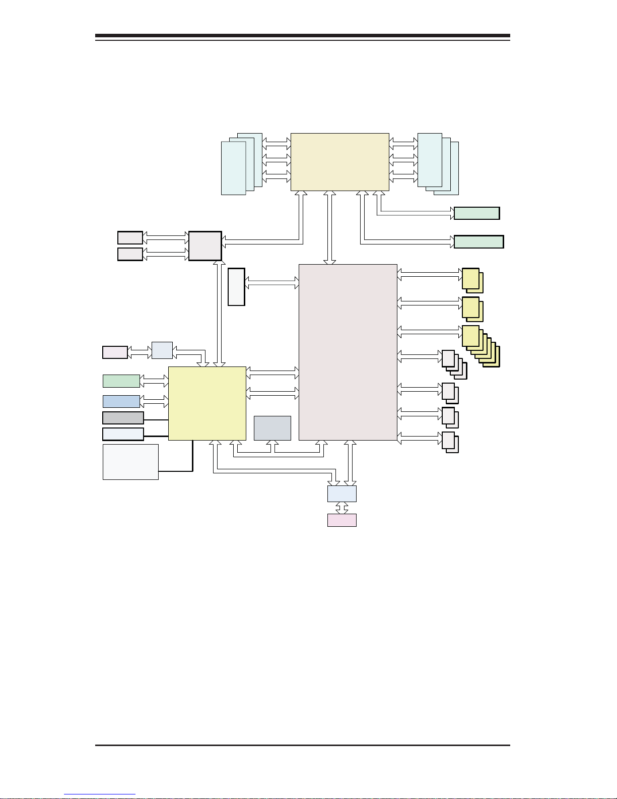
Figure 1-1. Intel PCH C612 Chipset:
System Block Diagram
Note: This is a general block diagram. Please see Chapter 5 for details.
SLOT 4
DDR4
3
2
1
SLOT 6
Processor
PCIe X16 G3
DMI2
4GB/s
PCI-E X16
PCI-E X4 G2
DMI2
PCI-E X16
#1 #2
Port 80
PCI-E X1 G2
USB 2.0
PCH
TPM
HEADER
USB 3.0
USB
BIOS
SPI
#3
PCIe X16 G3
SPI
LAN3
PHY
RGRMII
RJ45
* Temp. Sensor
* Voltage Sensor
* FAN PWM
BMC
AST2400
COM1
Header
VGA
CONN
BMC Boot
Flash
DDR3
LPC
SATA
DDR4
4
5
6
MUX
SPI
SLOT 2
6.0 Gb/S
S-SATA
port<2:3>
SATA DOM
PCIe X4 G2
PCI-E X8
USB 3.0
USB
Rear IO
Header
NC_SI
RJ45
RJ45
LAN2 MDI
LAN1 MDI
LPC SPI
MDI
H/W Monitoring
USB 2.0
Rear IO
LAN
i350/X540
6.0 Gb/S
S-SATA
port<0:1>
SATA
USB
6.0 Gb/S
I-SATA
port<0:5>
USB 2.0
Header
USB
SATA

1-9
Chapter 1: Introduction
1-4 Contacting Supermicro
Headquarters
Address: Super Micro Computer, Inc.
980 Rock Ave.
San Jose, CA 95131 U.S.A.
Tel: +1 (408) 503-8000
Fax: +1 (408) 503-8008
Email: marketing@supermicro.com (General Information)
support@supermicro.com (Technical Support)
Website:
www.supermicro.com
Europe
Address: Super Micro Computer B.V.
Het Sterrenbeeld 28, 5215 ML
's-Hertogenbosch, The Netherlands
Tel: +31 (0) 73-6400390
Fax: +31 (0) 73-6416525
Email: sales@supermicro.nl (General Information)
support@supermicro.nl (Technical Support)
rma@supermicro.nl (Customer Support)
Website:
www.supermicro.nl
Asia-Pacifi c
Address: Super Micro Computer, Inc.
3F, No. 150, Jian 1st Rd.
Zhonghe Dist., New Taipei City 235
Taiwan (R.O.C)
Tel: +886-(2) 8226-3990
Fax: +886-(2) 8226-3992
Email: support@supermicro.com.tw
Website:
www.supermicro.com.tw

5038K-i User's Manual
1-10
Notes

Chapter 2: Installation
2-1
Chapter 2
Installation
2-1 Overview
This chapter provides a quick setup checklist to get your 5038K-i up and running.
Following these steps in the order given should enable you to have the system
operational within a minimum amount of time. This quick setup assumes that
your system has come to you with the motherboard pre-installed.
2-2 Unpacking the System
You should inspect the box the system was shipped in and note if it was damaged
in any way. If the system itself shows damage you should fi le a damage claim with
the carrier who delivered it.
Decide on a suitable location for the system. It should be situated in a clean,
dust-free area that is well ventilated. Avoid areas where heat, electrical noise and
electromagnetic fi elds are generated. You will also need it plugged into a grounded
power outlet. Be sure to read the Warnings and Precautions in the next section.
2-3 Warnings and Precautions!
• Review the electrical and general safety precautions in Chapter 4.
• Use a regulating uninterruptible power supply (UPS) to protect the system from
power surges, voltage spikes and to keep your system operating in case of a
power failure.
• Allow the power supply units to cool before touching them.
2-2
5038K-i User's Manual
2-3 Accessing the Inside of the System
You may need to access the system periodically to perform maintenance or install
components such as hard drives. The system features two removable side covers,
allowing easy access to the system interior.
Caution: Except for short periods of time, do not operate the system without the
cover in place. The chassis cover must be in place to allow proper airfl ow .
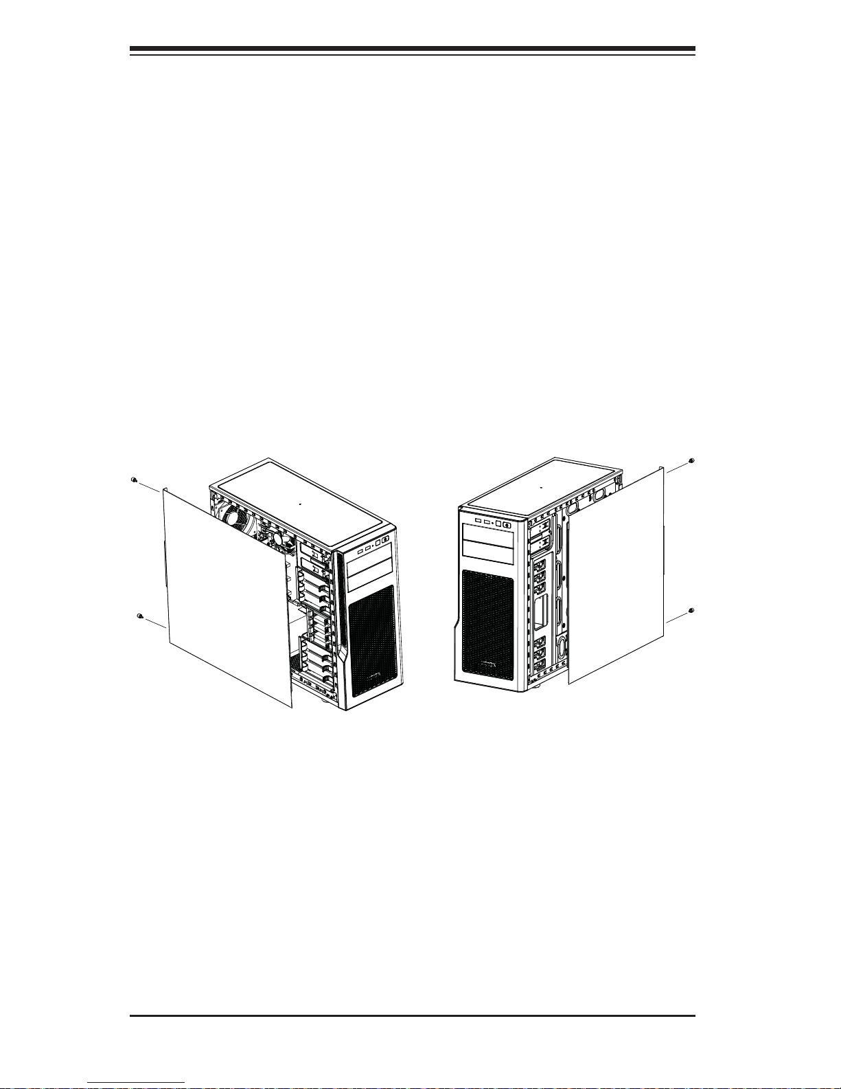
Left Side and Right Side Covers
Removing a Side Chassis Cover
1. Power down the system.
2. Remove the two thumb screws on the rear of the chassis.
3. Slide the cover back toward the rear of the chassis.
Figure 2-1. Removing the Chassis Side Covers
Chapter 2: Installation
2-3
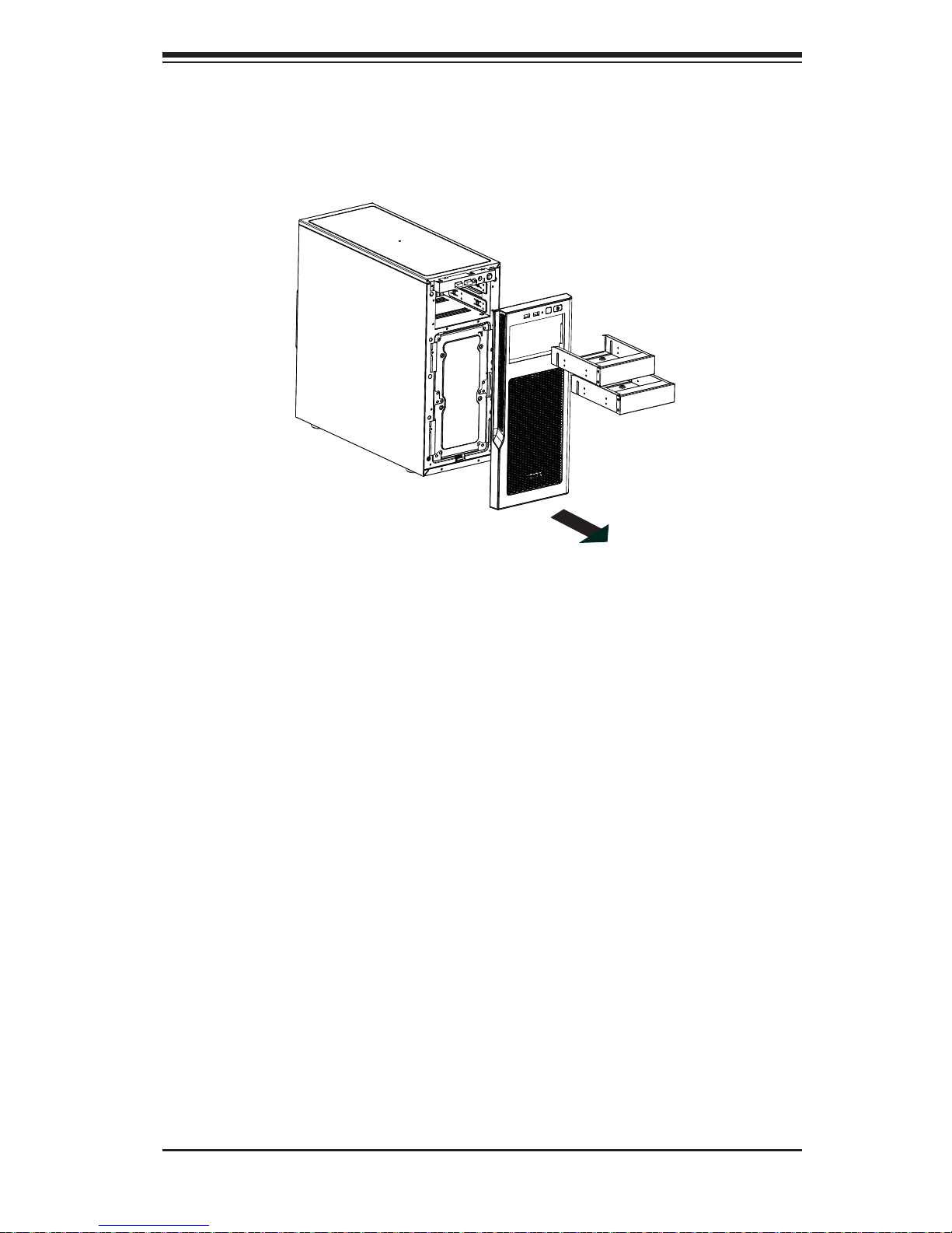
Front Bezel
Remove the front bezel by pulling it off from the bottom of the bezel.
Figure 2-2. Removing the Front Bezel

2-4
5038K-i User's Manual
Notes

Chapter 3: System Interface
3-1
Chapter 3
System Interface
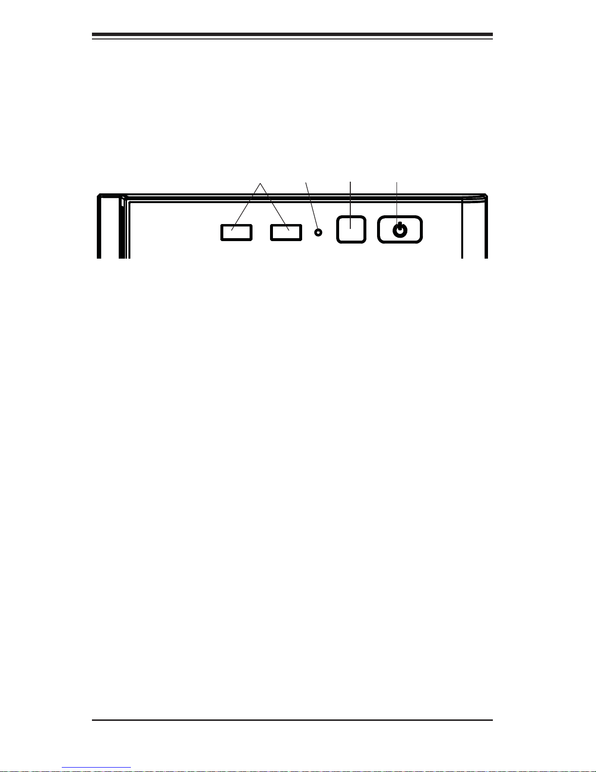
3-1 Overview
The control panel on the 5038K-i has one LED, a power button and a reset button.
This LED keeps you constantly informed of hard drive status and activity.
3-2 Control Panel Button
A single push-button is located on the front of the chassis.
Power
This is the main power button, which is used to apply or turn off the main system
power. T urning off system power with this button removes the main power but keeps
standby power supplied to the system.
Reset
Use the reset button to reboot the system.
3-2
5038K-i User's Manual
3-3 Front Panel Components
The 5038K-i features a front panel allowing easy access to the chassis power and
communication ports. In addition to the Power and Reset buttons, two USB 3.0
ports are also provided on the Front Panel. An LED indicates activity for the HHD.
Power
Button
Reset
Button
USB 3.0
Ports
Figure 3-1. Front Panel Components
HDD
Activity
4-1
Chapter 4: Warning Statements for AC Systems
Chapter 4
Standardized Warning Statements for AC Systems
4-1 About Standardized Warning Statements
The following statements are industry standard warnings, provided to warn the user
of situations which have the potential for bodily injury. Should you have questions
or experience difficulty, contact Supermicro's Technical Support department
for assistance. Only certifi ed technicians should attempt to install or confi gure
components.
Read this appendix in its entirety before installing or confi guring components in the
Supermicro chassis.
These warnings may also be found on our web site at http://www.supermicro.com/
about/policies/safety_information.cfm.
Warning Defi nition
Warning!
This warning symbol means danger. You are in a situation that could cause bodily
injury. Before you work on any equipment, be aware of the hazards involved with
electrical circuitry and be familiar with standard practices for preventing accidents.
警告の定義
この警告サインは危険を意味します。
人身事故につながる可能性がありますので、いずれの機器でも動作させる前に、
電気回路に含まれる危険性に注意して、標準的な事故防止策に精通して下さい。
此警告符号代表危险。
您正处于可能受到严重伤害的工作环境中。在您使用设备开始工作之前,必须充分
意识到触电的危险,并熟练掌握防止事故发生的标准工作程序。请根据每项警告结
尾的声明号码找到此设备的安全性警告说明的翻译文本。
此警告符號代表危險。
您正處於可能身體可能會受損傷的工作環境中。在您使用任何設備之前,請注意觸
電的危險,並且要熟悉預防事故發生的標準工作程序。請依照每一注意事項後的號
碼找到相關的翻譯說明內容。

4-2
5038K-i User's Manual
Warnung
WICHTIGE SICHERHEITSHINWEISE
Dieses Warnsymbol bedeutet Gefahr. Sie befi nden sich in einer Situation, die zu
Verletzungen führen kann. Machen Sie sich vor der Arbeit mit Geräten mit den
Gefahren elektrischer Schaltungen und den üblichen Verfahren zur Vorbeugung
vor Unfällen vertraut. Suchen Sie mit der am Ende jeder Warnung angegebenen
Anweisungsnummer nach der jeweiligen Übersetzung in den übersetzten
Sicherheitshinweisen, die zusammen mit diesem Gerät ausgeliefert wurden.
BEWAHREN SIE DIESE HINWEISE GUT AUF.
INSTRUCCIONES IMPORTANTES DE SEGURIDAD
Este símbolo de aviso indica peligro. Existe riesgo para su integridad física. Antes
de manipular cualquier equipo, considere los riesgos de la corriente eléctrica y
familiarícese con los procedimientos estándar de prevención de accidentes. Al
fi nal de cada advertencia encontrará el número que le ayudará a encontrar el texto
traducido en el apartado de traducciones que acompaña a este dispositivo.
GUARDE ESTAS INSTRUCCIONES.
IMPORTANTES INFORMATIONS DE SÉCURITÉ
Ce symbole d'avertissement indique un danger. Vous vous trouvez dans une
situation pouvant entraîner des blessures ou des dommages corporels. Avant
de travailler sur un équipement, soyez conscient des dangers liés aux circuits
électriques et familiarisez-vous avec les procédures couramment utilisées pour
éviter les accidents. Pour prendre connaissance des traductions des avertissements
fi gurant dans les consignes de sécurité traduites qui accompagnent cet appareil,
référez-vous au numéro de l'instruction situé à la fi n de chaque avertissement.
CONSERVEZ CES INFORMATIONS.
ןונקת תורהצהאהרהז
ןה תואבה תורהצהא ינפמ שמתשמה תא ריהזהל תנמ לע ,היישעתה ינקת יפ לע תורהז הלבח
ה וא תולאש שיו הדימב .תירשפא תיזיפי ,יהשלכ היעבב תולקתרוציל שי הכימת תקלחמ םע רשק
רידגהל וא ןיקתהל םיאשר דבלב םיכמסומ םיאנכט .ורקימרפוס לש תינכט תאה .םיביכר
אורקל שי .ורקימרפוס יזראמב םיביכרה
תרדגה וא תנקתה ינפל ואולמב חפסנה תא

4-3
Warning Statements for AC Systems
안전을 위한 주의사항
경고!
이 경고 기호는 위험이 있음을 알려 줍니다. 작업자의 신체에 부상을 야기 할 수
있는 상태에 있게 됩니다. 모든 장비에 대한 작업을 수행하기 전에 전기회로와
관련된 위험요소들을 확인하시고 사전에 사고를 방지할 수 있도록 표준 작업절차를
준수해 주시기 바랍니다.
해당 번역문을 찾기 위해 각 경고의 마지막 부분에 제공된 경고문 번호를
참조하십시오
BELANGRIJKE VEILIGHEIDSINSTRUCTIES
Dit waarschuwings symbool betekent gevaar. U verkeert in een situatie die
lichamelijk letsel kan veroorzaken. Voordat u aan enige apparatuur gaat werken,
dient u zich bewust te zijn van de bij een elektrische installatie betrokken risico's
en dient u op de hoogte te zijn van de standaard procedures om ongelukken te
voorkomen. Gebruik de nummers aan het eind van elke waarschuwing om deze te
herleiden naar de desbetreffende locatie.
BEWAAR DEZE INSTRUCTIES
. ﻲﻓ ﻚﻧا نأ ﻦﻜﻤﯾ ﺔﻟﺎﺣ ﻲﻓ ﺐﺒﺴﺘﺗ ﺔﺑﺎﺻا ﺔﯾﺪﺴﺟ ﺰﻣﺮﻟا اﺬھ ﻲﻨﻌﯾ ﺮﻄﺧ !ﺮﯾﺬﺤﺗ
نأ ﻞﺒﻗ يأ ﻰﻠﻋ ﻞﻤﻌﺗ تاﺪﻌﻣ،ﻛﻢﻠﻋ ﻰﻠﻋ ﻦ ﻦﻋ ﺔﻤﺟﺎﻨﻟا ﺮطﺎﺨﻤﻟﺎﺑ ﺮﺋاوﺪﻟا
ﺔﯿﺋﺎﺑﺮﮭﻜﻟا
ﻛوﺔﯾارد ﻰﻠﻋ ﻦ رﺎﻤﻤﻟﺎﺑتﺎﺳ ﺔﯿﺋﺎﻗﻮﻟا ﻟ ﻊﻨﻤعﻮﻗو يأثداﻮﺣ
ﻢﻗر مﺪﺨﺘﺳا نﺎﯿﺒﻟا صﻮﺼﻨﻤﻟا ﺔﯾﺎﮭﻧ ﻲﻓ ﺮﯾﺬﺤﺗ ﻞﻛ رﻮﺜﻌﻠﻟ ﺎﮭﺘﻤﺟﺮﺗ

4-4
5038K-i User's Manual
Installation Instructions
Warning!
Read the installation instructions before connecting the system to the power source.
設置手順書
システムを電源に接続する前に、設置手順書をお読み下さい。
警告
将此系统连接电源前,请先阅读安装说明。
警告
將系統與電源連接前,請先閱讀安裝說明。
Warnung
Vor dem Anschließen des Systems an die Stromquelle die Installationsanweisungen
lesen.
¡Advertencia!
Lea las instrucciones de instalación antes de conectar el sistema a la red de
alimentación.
Attention
Avant de brancher le système sur la source d'alimentation, consulter les directives
d'installation.
ﻟا تادﺎﺷرإ ﺮﻗاﺐﯿﻛﺮﺘ ﻞﯿﺻﻮﺗ ﻞﺒﻗ ﻰﻟإ مﺎﻈﻨﻟا ﺔﻗﺎﻄﻠﻟ رﺪﺼﻣ
אורקל שי רוקמל תכרעמה רוביח ינפל הנקתה תוארוה תאחתמ.
시스템을 전원에 연결하기 전에 설치 안내를 읽어주십시오.
Waarschuwing
Raadpleeg de installatie-instructies voordat u het systeem op de voedingsbron
aansluit.

4-5
Chapter 4: Warning Statements for AC Systems
Circuit Breaker
Warning!
This product relies on the building's installation for short-circuit (overcurrent)
protection. Ensure that the protective device is rated not greater than: 250 V, 20 A.
サーキット・ブレーカー
この製 品 は、短絡(過電流)保護装置がある建物での設置を前提としています。
保護装置の定格が250V、20Aを超えないことを確認下さい。
警告
此产品的短路(过载电流)保护由建筑物的供电系统提供,确保短路保护设备的额定电
流不大于250V,20A。
警告
此產品的短路(過載電流)保護由建築物的供電系統提供,確保短路保護設備的額定電
流不大於250V,20A。
Warnung
Dieses Produkt ist darauf angewiesen, dass im Gebäude ein Kurzschluss-
bzw. Überstromschutz installiert ist. Stellen Sie sicher, dass der Nennwert der
Schutzvorrichtung nicht mehr als: 250 V, 20 A beträgt.
¡Advertencia!
Este equipo utiliza el sistema de protección contra cortocircuitos (o sobrecorrientes)
del edifi cio. Asegúrese de que el dispositivo de protección no sea superior a: 250
V, 20 A.
Attention
Pour ce qui est de la protection contre les courts-circuits (surtension), ce produit
dépend de l'installation électrique du local. Vérifi ez que le courant nominal du
dispositif de protection n'est pas supérieur à :250 V, 20 A.
לע ךמתסמ הז רצומנגהה תעינמל םינבמב תנקתומה יכ אדוול שי .ילמשח רצק
רצקה ינפמ ןגמה רישכמה ילמשחהמ רתוי אל אוה-
250 V, 20 A
4-6
5038K-i User's Manual
Power Disconnection Warning
Warning!
The system must be disconnected from all sources of power and the power cord
removed from the power supply module(s) before accessing the chassis interior to
install or remove system components.
電源切断の警告
システムコンポーネントの取り付けまたは取り外しのために、シャーシー内部にアクセス
するには、
システムの電源はすべてのソースから切断され、電源コードは電源モジュールから取り
外す必要があります。
警告
在你打开机箱并安装或移除内部器件前,必须将系统完全断电,并移除电源线。
警告
在您打開機殼安裝或移除內部元件前,必須將系統完全斷電,並移除電源線。
경고!
이 제품은 전원의 단락(과전류)방지에 대해서 전적으로 건물의 관련 설비에
의존합니다. 보호장치의 정격이 반드시 250V(볼트), 20A(암페어)를 초과하지
않도록 해야 합니다.
Waarschuwing
Dit product is afhankelijk van de kortsluitbeveiliging (overspanning) van uw electrische
installatie. Controleer of het beveiligde aparaat niet groter gedimensioneerd is dan
220V, 20A.
ﺞﺘﻨﻤﻟا اﺬھ ﻰﻠﻋ ﺪﻤﺘﻌﯾ تاﺪﻌﻣ ﺔﯾﺎﻤﺤﻟا ةﺮﯿﺼﻘﻟاﺮﺋاوﺪﻟا ﻦﻣ ﺎﮭﺘﯿﺒﺜﺗ ﻢﺗ ﻲﺘﻟا ﻲﻓ
ﻰﻨﺒﻤﻟا
20A, 250V : ﻦﻣ ﺪﻛﺄﺗ نأ ﻢﯿﯿﻘﺗ زﺎﮭﺠﻟا ﻟاﻲﺋﺎﻗﻮ ﺲﯿﻟ ﻦﻣ ﺮﺜﻛأ
 Loading...