

Supermicro 5018A-MLTN4, Supero SuperServer 5018A-MLTN4 User Manual
SUPER
®
SUPERSERVER
5018A-MLTN4
®
Revision 1.0a

The information in this User’s Manual has been carefully reviewed and is believed to be accurate.
The vendor assumes no responsibility for any inaccuracies that may be contained in this document,
makes no commitment to update or to keep current the information in this manual, or to notify any
person or organization of the updates. Please Note: For the most up-to-date version of this
manual, please see our web site at www.supermicro.com.
Super Micro Computer, Inc. ("Supermicro") reserves the right to make changes to the product
described in this manual at any time and without notice. This product, including software and documentation, is the property of Supermicro and/or its licensors, and is supplied only under a license.
Any use or reproduction of this product is not allowed, except as expressly permitted by the terms
of said license.
IN NO EVENT WILL SUPERMICRO BE LIABLE FOR DIRECT, INDIRECT, SPECIAL, INCIDENTAL,
SPECULATIVE OR CONSEQUENTIAL DAMAGES ARISING FROM THE USE OR INABILITY TO
USE THIS PRODUCT OR DOCUMENTATION, EVEN IF ADVISED OF THE POSSIBILITY OF
SUCH DAMAGES. IN PARTICULAR, SUPERMICRO SHALL NOT HAVE LIABILITY FOR ANY
HARDWARE, SOFTW ARE, OR DA TA STORED OR USED WITH THE PRODUCT, INCLUDING THE
COSTS OF REPAIRING, REPLACING, INTEGRATING, INSTALLING OR RECOVERING SUCH
HARDWARE, SOFTWARE, OR DATA.
Any disputes arising between manufacturer and customer shall be governed by the laws of Santa
Clara County in the State of California, USA. The State of California, County of Santa Clara shall
be the exclusive venue for the resolution of any such disputes. Super Micro's total liability for all
claims will not exceed the price paid for the hardware product.
FCC Statement: This equipment has been tested and found to comply with the limits for a Class A
digital device pursuant to Part 15 of the FCC Rules. These limits are designed to provide reasonable
protection against harmful interference when the equipment is operated in a commercial environment. This equipment generates, uses, and can radiate radio frequency energy and, if not installed
and used in accordance with the manufacturer’s instruction manual, may cause harmful interference
with radio communications. Operation of this equipment in a residential area is likely to cause harmful
interference, in which case you will be required to correct the interference at your own expense.
California Best Management Practices Regulations for Perchlorate Materials: This Perchlorate warning applies only to products containing CR (Manganese Dioxide) Lithium coin cells. “Perchlorate
Material-special handling may apply. See www.dtsc.ca.gov/hazardouswaste/perchlorate”
WARNING: Handling of lead solder materials used in this
product may expose you to lead, a chemical known to the
State of California to cause birth defects and other reproductive harm.
Manual Revision 1.0a
Release Date: April 23, 2014
Unless you request and receive written permission from Super Micro Computer, Inc., you may not
copy any part of this document.
Information in this document is subject to change without notice. Other products and companies
referred to herein are trademarks or registered trademarks of their respective companies or mark
holders.
Copyright © 2014 by Super Micro Computer, Inc.
All rights reserved.
Printed in the United States of America

Preface
About This Manual
This manual is written for professional system integrators and PC technicians. It
provides information for the installation and use of the SuperServer 5018A-MLTN4.
Installation and maintenance should be performed by experienced technicians only .
The SuperServer 5018A-MLTN4 is a 1U rackmount server based on the SC512L200B server chassis and the Super A1SAM-2550F motherboard. Please refer to
our web site for updates on supported processors.
Manual Organization
Preface
Chapter 1: Introduction
The fi rst chapter provides a checklist of the main components included with the
server system and describes the main features of the A1SAM-2550F motherboard
and the SC512L-200B chassis.
Chapter 2: Server Installation
This chapter describes the steps necessary to install the SuperServer 5018A-ML TN4
into a rack and check out the server confi guration prior to powering up the system.
If your server was ordered without the processor and memory components, this
chapter will refer you to the appropriate sections of the manual for their installation.
Chapter 3: System Interface
Refer to this chapter for details on the system interface, which includes the functions
and information provided by the control panel on the chassis as well as other LEDs
located throughout the system.
Chapter 4: Standardized Warning Statements
You should thoroughly familiarize yourself with this chapter for a general overview
of safety precautions that should be followed when installing and servicing the
SuperServer 5018A-MLTN4.
iii

SUPERSERVER 5018A-MLTN4 User's Manual
Chapter 5: Advanced Motherboard Setup
Chapter 5 provides detailed information on the A1SAM-2550F motherboard, including the locations and functions of connectors, headers and jumpers. Refer to
this chapter when adding or removing main memory and when reconfi guring the
motherboard.
Chapter 6: Advanced Chassis Setup
Refer to Chapter 6 for detailed information on the SC512L-200B chassis. Y ou should
follow the procedures given in this chapter when installing, removing or reconfi gur-
ing Serial ATA or peripheral drives and when replacing system power supply units
and cooling fans.
Chapter 7: BIOS
The BIOS chapter includes an introduction to BIOS and provides detailed information on running the CMOS Setup Utility.
Appendix A: BIOS POST Error Codes
Appendix B: System Specifi cations
iv

Notes
Preface
v

SUPERSERVER 5018A-MLTN4 User's Manual
Table of Contents
Chapter 1 Introduction
1-1 Overview .........................................................................................................1-1
1-2 Motherboard Features .....................................................................................1-2
Processors ......................................................................................................1-2
Memory ...........................................................................................................1-2
SATA ..............................................................................................................1-2
PCI Expansion Slots ....................................................................................... 1-2
I/O Ports .......................................................................................................... 1-2
1-3 Server Chassis Features ................................................................................ 1-3
System Power ................................................................................................. 1-3
SATA Subsystem ............................................................................................. 1-3
Control Panel .................................................................................................. 1-3
Cooling System ............................................................................................... 1-3
1-4 Contacting Supermicro ....................................................................................1-5
Chapter 2 Server Installation
2-1 Overview .........................................................................................................2-1
2-2 Unpacking the System .................................................................................... 2-1
2-3 Preparing for Setup .........................................................................................2-1
Choosing a Setup Location .............................................................................2-1
2-4 Warnings and Precautions .............................................................................. 2-2
Rack Precautions ............................................................................................ 2-2
Server Precautions ..........................................................................................2-2
Rack Mounting Considerations ....................................................................... 2-3
Ambient Operating Temperature ................................................................ 2-3
Reduced Airfl ow .........................................................................................2-3
Mechanical Loading ................................................................................... 2-3
Circuit Overloading .....................................................................................2-3
Reliable Ground ......................................................................................... 2-3
2-5 Installing the System into a Rack ...................................................................2-4
Identifying the Sections of the Rack Rails ...................................................... 2-4
Installing the Inner Rail Extension .................................................................. 2-5
Installing the Outer Rails to the Rack ............................................................. 2-6
Installing the Chassis into a Rack...................................................................2-8
Mid-Mount Telco Rack..................................................................................... 2-9
Installing the Chassis into a Rack in Mid-Mount Position .............................. 2-9
vi

Table of Contents
Chapter 3 System Interface
3-1 Overview .........................................................................................................3-1
3-2 Control Panel Buttons ..................................................................................... 3-1
Reset ...............................................................................................................3-1
Power ..............................................................................................................3-1
3-3 Control Panel LEDs ........................................................................................ 3-2
Overheat/Fan Fail LED ................................................................................... 3-2
NIC2 ................................................................................................................3-2
NIC1 ................................................................................................................3-2
HDD .................................................................................................................3-3
Power ..............................................................................................................3-3
3-4 SATA Drive Carrier LEDs ................................................................................ 3-3
Chapter 4 Standardized Warning Statements for AC Systems
4-1 About Standardized Warning Statements .......................................................4-1
Warning Defi nition ........................................................................................... 4-1
Installation Instructions ....................................................................................4-4
Circuit Breaker ................................................................................................ 4-5
Power Disconnection Warning ........................................................................ 4-6
Equipment Installation ..................................................................................... 4-8
Restricted Area ................................................................................................ 4-9
Battery Handling ............................................................................................4-10
Redundant Power Supplies .......................................................................... 4-12
Backplane Voltage ........................................................................................ 4-13
Comply with Local and National Electrical Codes ........................................ 4-14
Product Disposal ........................................................................................... 4-15
Hot Swap Fan Warning ................................................................................. 4-16
Power Cable and AC Adapter ...................................................................... 4-18
Chapter 5 Advanced Motherboard Setup
5-1 Handling the Motherboard .............................................................................. 5-1
Precautions .....................................................................................................5-1
Unpacking .......................................................................................................5-2
5-2 Motherboard Installation ..................................................................................5-2
5-3 Connecting Cables .......................................................................................... 5-3
Connecting Data Cables ................................................................................. 5-3
Connecting Power Cables .............................................................................. 5-3
Connecting the Control Panel ......................................................................... 5-3
5-4 Rear I/O Ports ................................................................................................. 5-4
5-5 Onboard Processor and Heatsink ................................................................... 5-5
5-6 Installing Memory Modules ............................................................................. 5-5
vii

SUPERSERVER 5018A-MLTN4 User's Manual
Installing & Removing DIMMs ......................................................................... 5-5
Memory Support ......................................................................................... 5-6
Memory Population Guidelines ....................................................................... 5-6
5-7 Adding PCI Cards ........................................................................................... 5-7
5-8 Motherboard Details ........................................................................................ 5-8
Motherboard Layout ........................................................................................ 5-8
A1SAM-2550F Quick Reference Table ........................................................... 5-8
5-9 Connector Defi nitions ................................................................................... 5-10
ATX Power Connector .............................................................................. 5-10
Power Button ...........................................................................................5-10
Reset Button .............................................................................................5-10
Power Fail LED ........................................................................................ 5-10
Overheat (OH)/Fan Fail/PWR Fail/UID LED .............................................5-11
NIC2 (LAN2) LED ......................................................................................5-11
HDD LED ...................................................................................................5-11
Power On LED ..........................................................................................5-11
NMI Button ............................................................................................... 5-12
Fan Headers .............................................................................................5-12
Chassis Intrusion ...................................................................................... 5-12
Universal Serial Bus (USB) ...................................................................... 5-12
Serial Ports ............................................................................................... 5-13
Power SMB (I
2
C) Connector .................................................................... 5-13
Onboard Speaker (SP1) ........................................................................... 5-13
Power LED/Speaker .................................................................................5-13
DOM Power Connector ............................................................................ 5-14
TPM/Port 80 Header ................................................................................ 5-14
Overheat LED/Fan Fail ............................................................................ 5-14
LAN3/LAN4 LED Indication Header ......................................................... 5-14
LAN (Ethernet) Ports ................................................................................ 5-15
Unit Identifi er Switch/UID LED Indicators ................................................ 5-15
System Management Bus Header ........................................................... 5-16
Standby Power ......................................................................................... 5-16
Overheat LED Header .............................................................................. 5-16
5-10 Jumper Settings ............................................................................................5-17
Explanation of Jumpers ................................................................................ 5-17
CMOS Clear ............................................................................................. 5-17
LAN1/LAN2 Enable/Disable ..................................................................... 5-17
VGA Enable/Disable ................................................................................. 5-18
Watch Dog ................................................................................................5-18
viii

Table of Contents
BMC Enable ............................................................................................ 5-18
PCI-E Slot SMB Enable ........................................................................... 5-18
BIOS Recovery Enable ............................................................................ 5-19
USB Wake-Up Enable .............................................................................. 5-19
5-11 Onboard Indicators ........................................................................................5-19
LAN Port LEDs ......................................................................................... 5-19
IPMI Dedicated LAN LEDs ....................................................................... 5-19
Onboard Power LED ............................................................................... 5-20
Overheat/PWR Fail/Fan Fail LED ............................................................ 5-20
Unit Identifi cation LED .............................................................................. 5-20
5-12 SATA Ports .................................................................................................... 5-21
SATA Ports ............................................................................................... 5-21
5-13 Installing Software .........................................................................................5-22
SuperDoctor® 5 ............................................................................................ 5-23
5-14 Onboard Battery ............................................................................................ 5-24
Chapter 6 Advanced Chassis Setup
6-1 Static-Sensitive Devices ..................................................................................6-1
Precautions .....................................................................................................6-1
Unpacking .......................................................................................................6-1
6-2 Control Panel ..................................................................................................6-2
6-3 Removing the Chassis Cover .........................................................................6-2
6-4 System Fan .....................................................................................................6-3
6-5 Installing Hard Drives ...................................................................................... 6-5
6-6 Installing a DVD or CD-ROM Drive ................................................................ 6-7
6-7 PCI Slot Setup ................................................................................................ 6-8
6-8 Power Supply ..................................................................................................6-9
Power Supply Failure ......................................................................................6-9
Chapter 7 BIOS
7-1 Introduction ......................................................................................................7-1
Starting BIOS Setup Utility .............................................................................. 7-1
How To Change the Confi guration Data .........................................................7-1
How to Start the Setup Utility ......................................................................... 7-2
7-2 Main Setup ...................................................................................................... 7-2
7-3 Advanced Setup Confi gurations......................................................................7-4
7-4 IPMI Confi guration ........................................................................................7-20
7-4 Event Logs .................................................................................................... 7-22
7-5 Security Settings ........................................................................................... 7-24
7-6 Boot Settings ................................................................................................. 7-27
7-7 Save & Exit ................................................................................................... 7-29
ix

SUPERSERVER 5018A-MLTN4 User's Manual
Appendix A BIOS Post Error Codes
Appendix B System Specifi cations
x

Chapter 1: Introduction
Chapter 1
Introduction
1-1 Overview
The SuperServer 5018A-ML TN4 is comprised of two main subsystems: the SC512L200B 1U chassis and the A1SAM-2550F motherboard. Please refer to our web
site for information on operating systems that have been certifi ed for use with the
SuperServer 5018A-MLTN4 (www.supermicro.com).
In addition to the motherboard and chassis, various hardware components have
been included with the system, as listed below:
• One 10-cm PWM blower fan (FAN-0038L4)
Note: For your system to work properly, please follow the links below to download
all necessary drivers/utilities and the user’s manual for your server.
• Supermicro product manuals: http://www.supermicro.com/support/manuals/
• Product drivers and utilities: ftp://ftp.supermicro.com
• Product safety info: http://super-dev/about/policies/safety_information.cfm
• If you have any questions, please contact our support team at:
support@supermicro.com
1-1

SUPERSERVER 5018A-MLTN4 User's Manual
1-2 Motherboard Features
At the heart of the SuperServer 5018A-MLTN4 lies the A1SAM-2550F, an embedded processor motherboard. Below are the main features of the A1SAM-2550F. See
Figure 1-1 for a block diagram of the motherboard.
Processors
The A1SAM-2550F supports a single Intel® C2000 T ri-Gate 22nm SoC (System-ona Chip) Series 4-core processor in an FCBGA 1283 package (embedded processor).
Memory
The A1SAM-2550F has four DIMM slots that can support up to 64GB of DDR31600/1333 Unbuffered (UDIMM) ECC/Non-ECC memory. DIMMs of the same size
and speed should be used. See Chapter 5 for details.
SATA
A SATA controller is integrated into the chipset to provide a six-port Serial ATA subsystem (4x SATA 2.0 and 2x SATA 3.0 ports). The SATA drives are hot-swappable
units.
PCI Expansion Slots
The motherboard includes one PCI-Express 2.0 x8 and one PCI-Express 2.0 x4
slot. The system supports one PCI-Express 3.0 x8 card with the use of an optional
installed riser card.
I/O Ports
The I/O ports include a COM port, a VGA port, four USB 2.0 ports, four Gb LAN
(NIC) ports and a dedicated IPMI LAN port.
1-2

Chapter 1: Introduction
1-3 Server Chassis Features
The following is a general outline of the main features of the SC512L-200B chassis.
System Power
The SC512L-20 0B chassis includes a single 200W power supply.
SATA Subsystem
The SC512L-20 0B c hassis was d esigne d to suppor t t wo interna l 3.5" SATA har d
drives.
Control Panel
The SC512L-200B's control panel provides important system monitoring and control
information. LEDs indicate power on, network activity, hard disk drive activity and
system overheat conditions. The control panel also includes a main power button
and a system reset button.
Cooling System
The SC512L-200B chassis features one 10-cm PWM blower fan, which connects to
a chassis fan header on the motherboard. Fan speed is controlled by IPMI.
1-3
SUPERSERVER 5018A-MLTN4 User's Manual
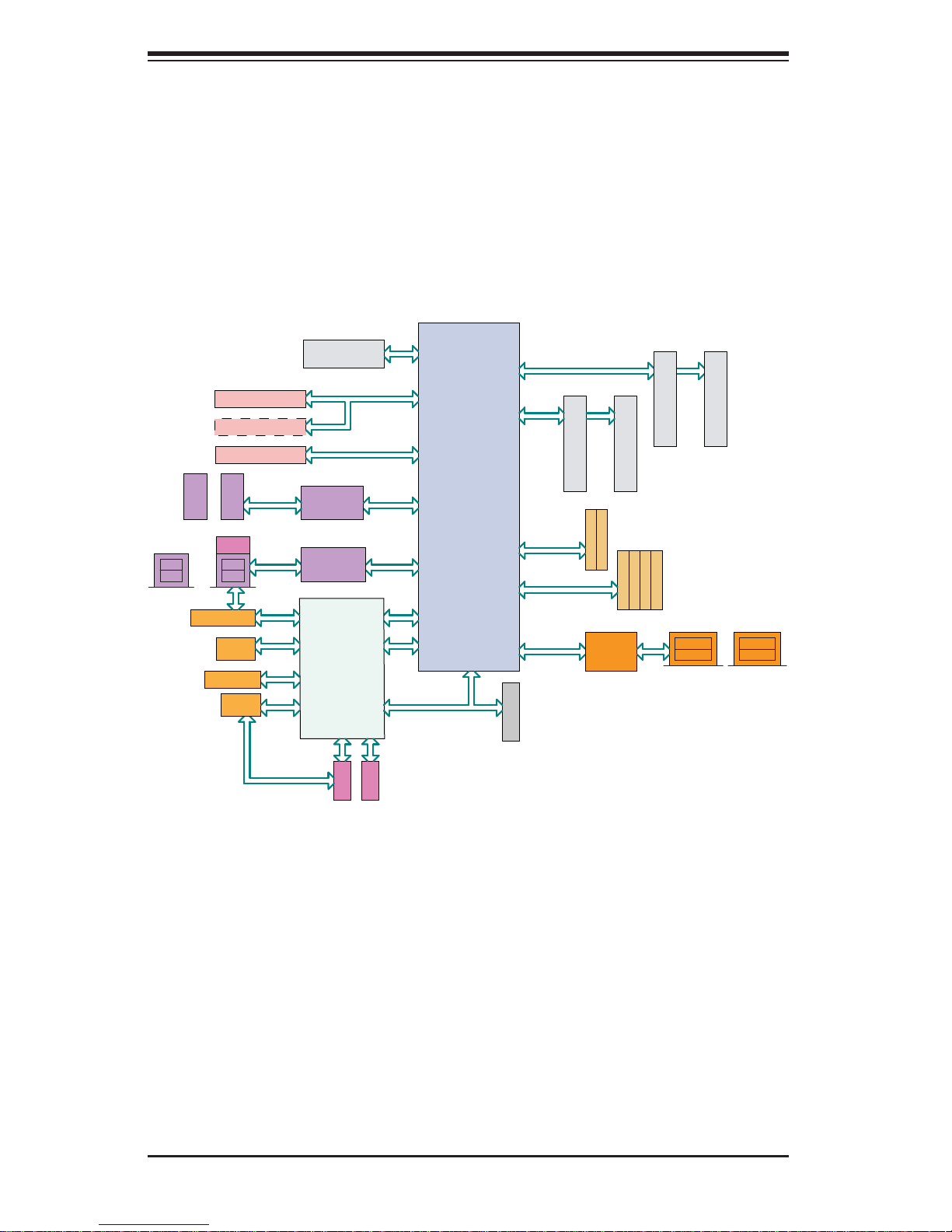
Figure 1-1. A1SAM-2550F Motherboard:
System Block Diagram
Note: This is a general block diagram. Please see Chapter 5 for details.
REAR
JPCIE1
JPCIE2
(Optional)
JPCIE3
HEADER
USB
+
GbE LAN
RTL8211E
PCIE 2.0 x 8 SLOT
PCIE 2.0 x 4 SLOT
PCIE 2.0 x 4 SLOT
TYPE-A
+
USB 2.0
REAR
RJ45
USB 2.0
VGA
REAR
FAN x 3
0Ohm
NI
FLASH 128Mb
PCIE x 8
PCIE x 4
USB Hub
PD720114
USB Hub
PD720114
AST2400
TX/RX
(debug)
UART1 UART2
COM1
USB 2.0
USB 2.0
PCIE x 1
LPC
COM2
SPI
Rangeley
AVOTON SOC
PEG [8..15]
PEG [4..7]
USB 1
USB 0
PEG [0]
USB [2:3]
LPC
CHB CHB
SATA GEN3
SATA GEN2
SGMII x 4
TPM HDR
A2
CHA CHA
DIMMB2
SATA 3.0
SATA 3.0
10BASE-T/100BASE-T/1000BASE-T
88E1543
B1B2
DIMMB1
SATA 2.0
SATA 2.0
SATA 2.0
DIMMA2
SATA 2.0
A1
DIMMA1
LAN3
LAN1
REAR REAR
LAN4
+
LAN2
REAR
1-4

1-4 Contacting Supermicro
Headquarters
Address: Super Micro Computer, Inc.
980 Rock Ave.
San Jose, CA 95131 U.S.A.
Tel: +1 (408) 503-8000
Fax: +1 (408) 503-8008
Email: marketing@supermicro.com (General Information)
support@supermicro.com (Technical Support)
Chapter 1: Introduction
Web Site:
Europe
Address: Super Micro Computer B.V.
Tel: +31 (0) 73-6400390
Fax: +31 (0) 73-6416525
Email: sales@supermicro.nl (General Information)
Web Site:
Asia-Pacifi c
Address: Super Micro Computer, Inc.
www.supermicro.com
Het Sterrenbeeld 28, 5215 ML
's-Hertogenbosch, The Netherlands
support@supermicro.nl (Technical Support)
rma@supermicro.nl (Customer Support)
www.supermicro.com
3F, No. 150, Jian 1st Rd.
Zhonghe Dist., New Taipei City 235
Tel: +886-(2) 8226-3990
Fax: +886-(2) 8226-3992
Email: support@supermicro.com.tw
Web Site:
Taiwan (R.O.C)
www.supermicro.com.tw
1-5

SUPERSERVER 5018A-MLTN4 User's Manual
Notes
1-6

Chapter 2: Server Installation
Chapter 2
Server Installation
2-1 Overview
This chapter provides a quick setup checklist to get your SuperServer 5018A-ML TN4
up and running. Following the steps in the order given should enable you to have
the system operational within a minimal amount of time. This quick setup assumes
that your system has come to you with the processor and memory preinstalled. If
your system is not already fully integrated with a motherboard, processor, system
memory etc., please turn to the chapter or section noted in each step for details on
installing specifi c components.
2-2 Unpacking the System
You should inspect the box the server was shipped in and note if it was damaged
in any way. If the server itself shows damage, you should fi le a damage claim with
the carrier who delivered it.
Decide on a suitable location for the rack unit that will hold the server. It should
be situated in a clean, dust-free area that is well ventilated. Avoid areas where
heat, electrical noise and electromagnetic fi elds are generated. You will also need
it placed near a grounded power outlet. Read the Rack and Server Precautions in
the next section.
2-3 Preparing for Setup
The box the SuperServer 5018A-MLTN4 was shipped in should include two sets of
rail assemblies, six rail mounting brackets and the mounting screws you will need to
install the system into the rack. Follow the steps in the order given to complete the
installation process in a minimal amount of time. Please read this section in its entirety before you begin the installation procedure outlined in the sections that follow.
Choosing a Setup Location
• Leave enough clearance in front of the rack to enable you to open the front door
completely (~25 inches) and approximately 30 inches of clearance in the back
of the rack to allow for suffi cient airfl ow and ease in servicing.This product is for
installation only in a Restricted Access Location (dedicated equipment rooms,
service closets and the like).
2-1

SUPERSERVER 5018A-MLTN4 User's Manual
• This product is not suitable for use with visual display work place devices
acccording to §2 of the the German Ordinance for Work with Visual Display
Units.
2-4 Warnings and Precautions
Rack Precautions
• Ensure that the leveling jacks on the bottom of the rack are fully extended to
the fl oor with the full weight of the rack resting on them.
• In single rack installation, stabilizers should be attached to the rack. In multiple
rack installations, the racks should be coupled together.
• Always make sure the rack is stable before extending a component from the
rack.
• You should extend only one component at a time - extending two or more si-
multaneously may cause the rack to become unstable.
Server Precautions
• Review the electrical and general safety precautions in Chapter 4.
• Determine the placement of each component in the rack before you install the
rails.
• Install the heaviest server components on the bottom of the rack fi rst, and then
work up.
• Use a regulating uninterruptible power supply (UPS) to protect the server from
power surges, voltage spikes and to keep your system operating in case of a
power failure.
• Allow the hot plug SATA drives and power supply modules to cool before touch-
ing them.
• Always keep the rack's front door and all panels and components on the servers
closed when not servicing to maintain proper cooling.
2-2
Chapter 2: Server Installation
Rack Mounting Considerations
Ambient Operating Temperature
If installed in a closed or multi-unit rack assembly, the ambient operating temperature of the rack environment may be greater than the ambient temperature of the
room. Therefore, consideration should be given to installing the equipment in an
environment compatible with the manufacturer’s maximum rated ambient temperature (Tmra).
Reduced Airfl ow
Equipment should be mounted into a rack so that the amount of airfl ow required
for safe operation is not compromised.
Mechanical Loading
Equipment should be mounted into a rack so that a hazardous condition does not
arise due to uneven mechanical loading.
Circuit Overloading
Consideration should be given to the connection of the equipment to the power
supply circuitry and the effect that any possible overloading of circuits might have
on overcurrent protection and power supply wiring. Appropriate consideration of
equipment nameplate ratings should be used when addressing this concern.
Reliable Ground
A reliable ground must be maintained at all times. To ensure this, the rack itself
should be grounded. Particular attention should be given to power supply connections other than the direct connections to the branch circuit (i.e. the use of power
strips, etc.).
Warning! To prevent bodily injury when mounting or servicing this unit in a
rack, you must take special precautions to ensure that the system remains
stable. The following guidelines are provided to ensure your safety:
• This unit should be mounted at the bottom of the rack if it is the only unit in
the rack.
• When mounting this unit in a partially fi lled rack, load the rack from the bottom
to the top with the heaviest component at the bottom of the rack.
• If the rack is provided with stabilizing devices, install the stabilizers before
mounting or servicing the unit in the rack.
2-3
SUPERSERVER 5018A-MLTN4 User's Manual
2-5 Installing the System into a Rack
This section provides information on installing the SuperServer 5018A-MLTN4 into
a rack unit with the rack rails provided.
There are a variety of rack units on the market, which may mean the assembly
procedure will differ slightly. You should also refer to the installation instructions that
came with the rack unit you are using.
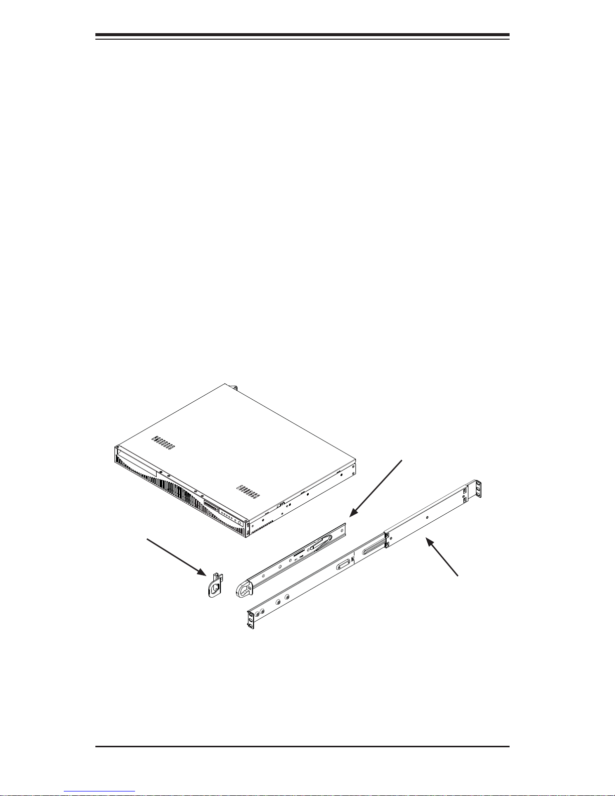
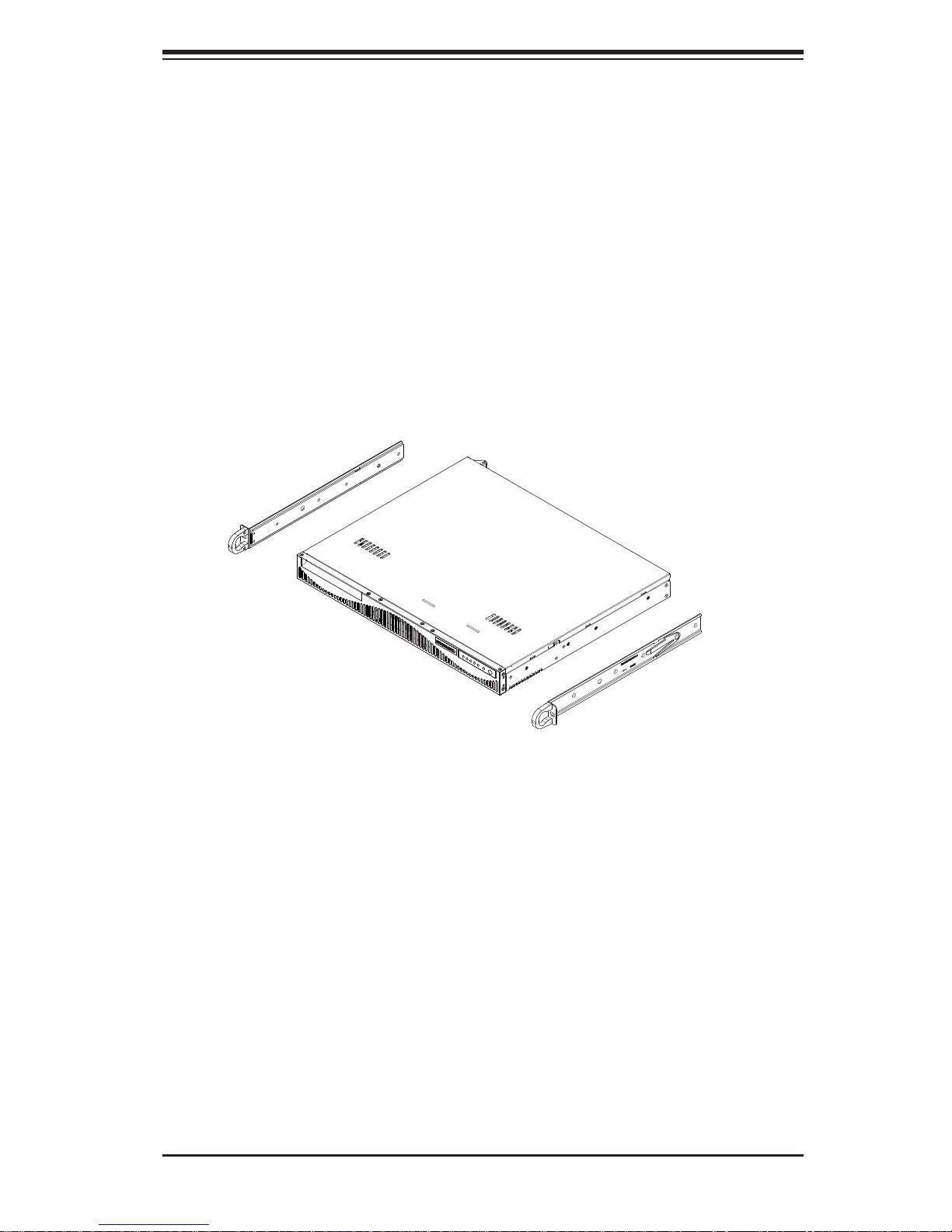
Identifying the Sections of the Rack Rails
The chassis package includes two rack rail assemblies in the rack mounting kit. Each
assembly consists of two sections: an inner fi xed chassis rail that secures directly to
the server chassis, and an outer fi xed rack rail that secures directly to the rack itself.
The SC512F comes with "chassis ears" that allow the chassis to use generic rails.
Chassis Ears
Figure 2-1. Identifying the Sections of the Rack Rails
(Right side rail shown)
Inner Rails
Outer Rails
2-4
Chapter 2: Server Installation
Installing the Inner Rail Extension
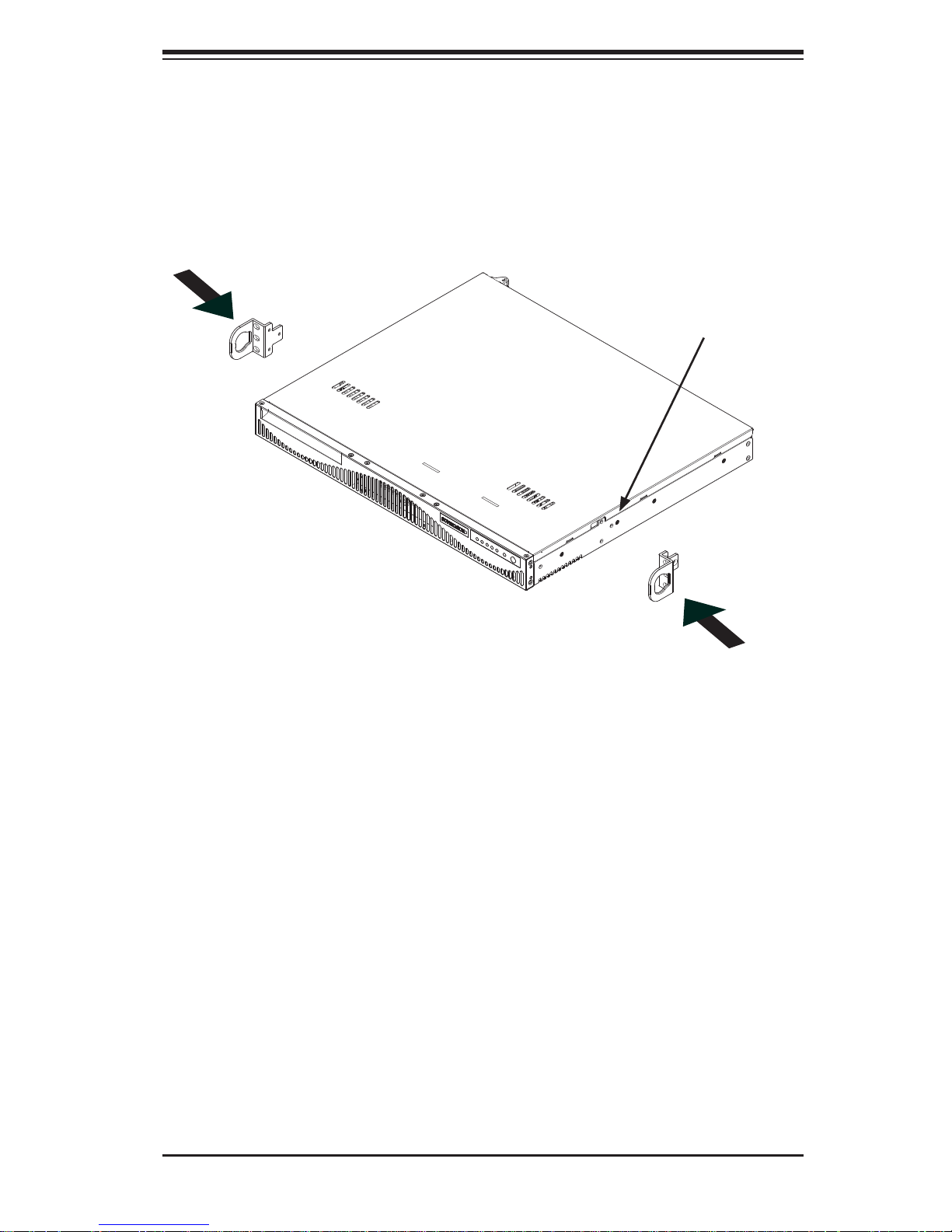
The SC512F includes chassis ears that you must remove before installing the rails.
Removing the Chassis Ears
1. Locate and remove the three screws holding the chassis ear in place.
2. Repeat step on with the other chassis ear.
Figure 2-2. Installing Rear Inner Chassis Rails
Installing the Inner Rails
1. Place the inner rail on the side of the chassis aligning the hooks of the chassis with the rail holes.
2. Slide the rail toward the front of the chassis to secure the rail in place.
3. Secure the chassis with four screws.
4. Repeat steps 1-3 for the other inner rail extension.
2-5
SUPERSERVER 5018A-MLTN4 User's Manual
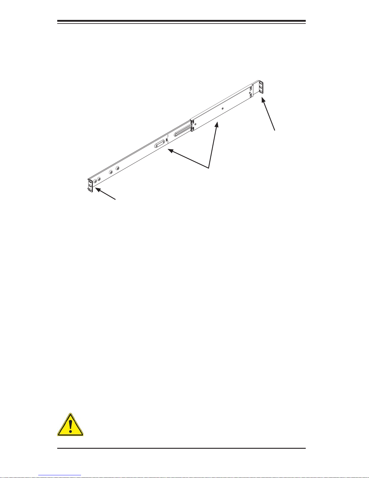
Attach Outer Rack Rails
Secure to the
Rear of the Rack
Together
Secure to the
Front of the Rack
Figure 2-3. Assembling the Outer Rails
Installing the Outer Rails to the Rack
Installing the Outer Rails
1. Attach the short bracket to the outside of the long bracket. You must align the
pins with the slides. Also, both bracket ends must face the same direction.
2. Adjust both the short and long brackets to the proper distance so that the rail
fi ts snugly into the rack.
3. Secure the long bracket to the front side of the outer rail with two M5 screws
and the short bracket to the rear side of the outer rail with three M5 screws.
Use a washer with each screw.
4. Repeat steps 1-4 for the left outer rail.
Warning: do not pick up the server with the front handles. They are designed to pull the system from a rack only.
2-6
Chapter 2: Server Installation
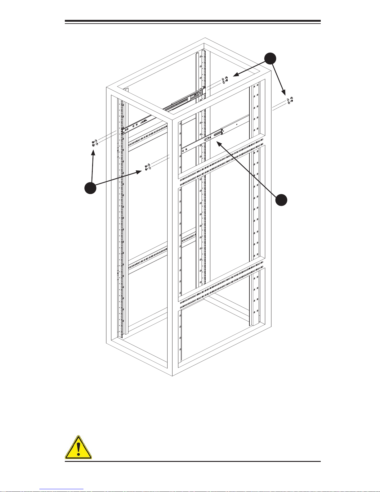
1
3
1
3
1
2
Figure 2-4. Installing the Outer Rails to the Server Rack
Note: this fi gure is for illustrative purposes only. Always install servers to the bot-
tom of a rack fi rst.
Stability hazard. The rack stabilizing mechanism must be in place, or the
rack must be bolted to the fl oor before you slide the unit out for servicing.
Failure to stabilize the rack can cause the rack to tip over.
2-7
SUPERSERVER 5018A-MLTN4 User's Manual
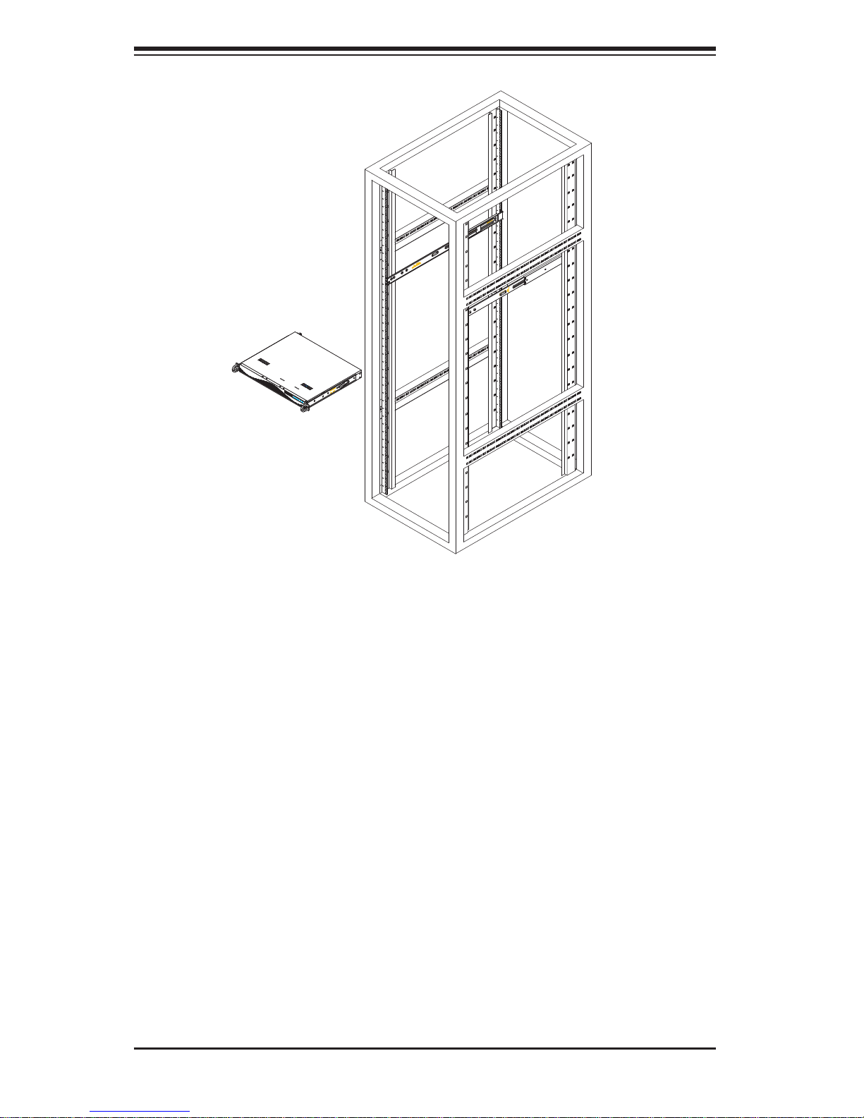
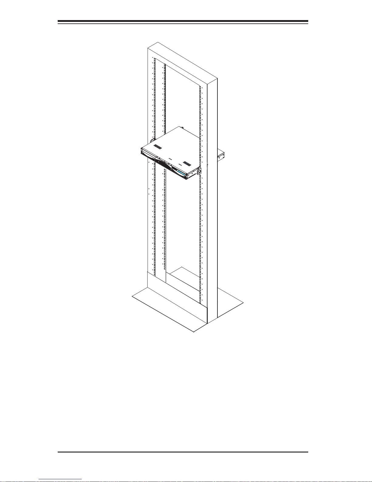
Figure 2-5. Installing the Chassis into a Rack
Installing the Chassis into a Rack
Installing the Chassis
1. Confi rm that the inner rails are attached to the chassis. Also, confi rm that the
outer rails are installed on the rack.
2. Align chassis rails with the front of the rack rails.
3. Slide the chassis rails into the rack rails, keeping the pressure even on both
sides (It may be necessary to depress the locking tabs when inserting). When
the server has been pushed completely into the rack, you should hear the
locking tabs "click" into the locked position.
4. (Optional) Insert and tightening the thumbscrews that hold the front of the
server to the rack.
Note: this fi gure is for illustrative purposes only. Always install servers to the bot-
tom of a rack fi rst.
2-8
Chapter 2: Server Installation
Mid-Mount Telco Rack
The SC512.supports Telco rack installation. The SC512 chassis compact design
allows the chassis to be installed into a Telco rack without the use of rails.
Place Chassis Ears
Here
Figure 2-6. Placing the Chassis Ears for Telco Rack Installation
Installing the Chassis into a Rack in Mid-Mount Position
Instaling into a Mid-Mount Position Rack
1. If it is necessary to install the chassis in a mid-mount Telco rack, remove the
chassis rails and the chassis ears (if the ears are installed at the front of the
chassis).
2. Locate the three screw holes in the middle of the chassis and secure the ears
to the chassis with three fl at head screws. Make sure the screws are secure,
but do not over tighten the screws.
2-9
SUPERSERVER 5018A-MLTN4 User's Manual
Figure 2-7. Installing the Server into a Telco Rack
1. Hold the chassis in the telco rack and screw the chassis to the rack using the
three screw holes located in the chassis ears.
2. The chassis is held in place by the chassis ears and does not slide in and out
of place.
Note: this fi gure is for illustrative purposes only. Always install servers to the bot-
tom of a rack fi rst.
2-10
Chapter 3: System Interface
Chapter 3
System Interface
3-1 Overview
There are several LEDs on the control panel as well as others on the SATA drive
carriers to keep you constantly informed of the overall status of the system as well
as the activity and health of specifi c components. There are also two buttons on
the chassis control panel and an on/off switch on the power supply. This chapter
explains the meanings of all LED indicators and the appropriate response you may
need to take.
3-2 Control Panel Buttons
There are two push-buttons located on the front of the chassis: a reset button and
a power on/off button.
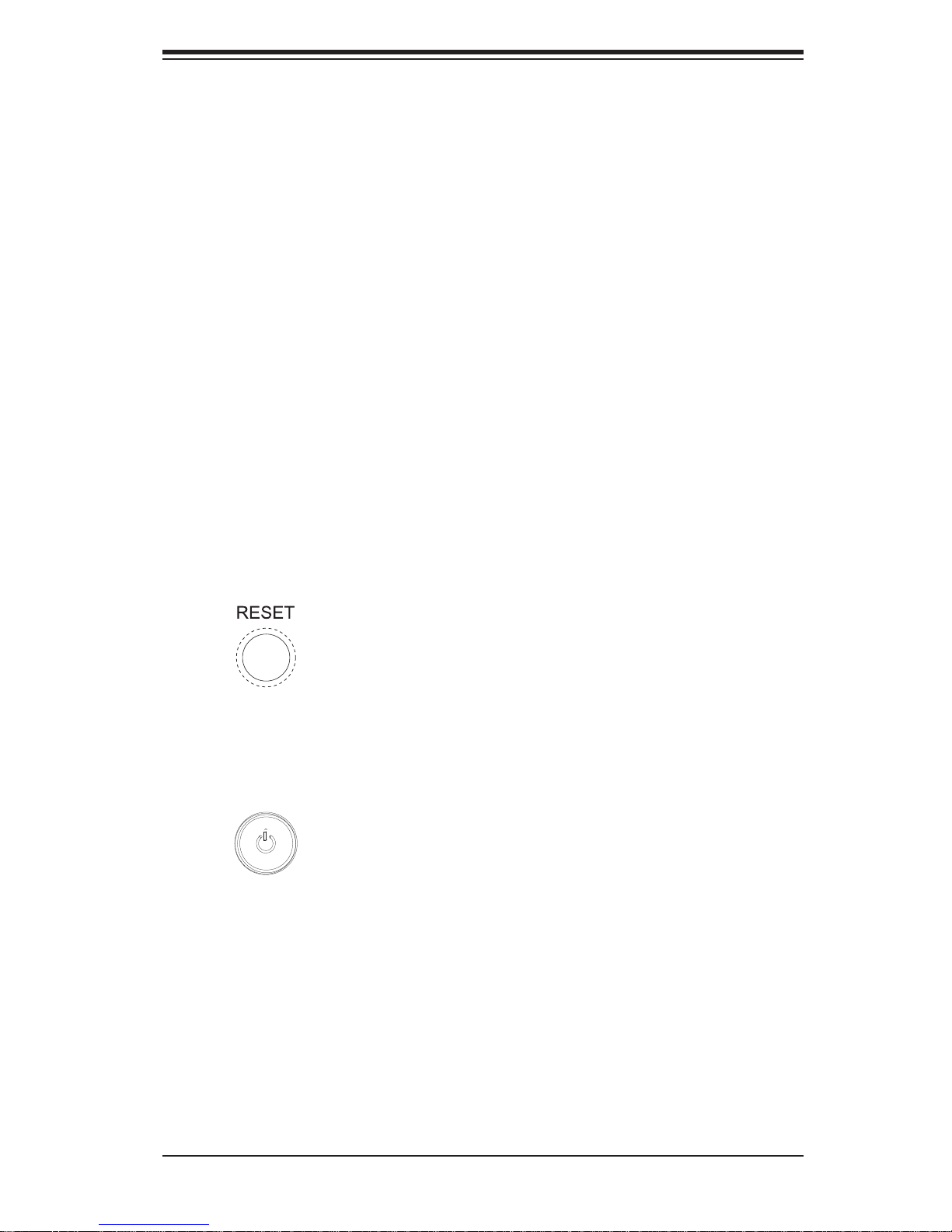
Reset
The reset button reboots the system.
Power
This is the main power button, which is used to apply or turn off the main system
power. T urning off system power with this button removes the main power but keeps
standby power supplied to the system.
3-1
SUPERSERVER 5018A-MLTN4 User's Manual
3-3 Control Panel LEDs
The control panel located on the front of the SC512L-200B chassis has fi ve LEDs.
These LEDs provide you with critical information related to different parts of the
system. This section explains what each LED indicates when illuminated and any
corrective action you may need to take.
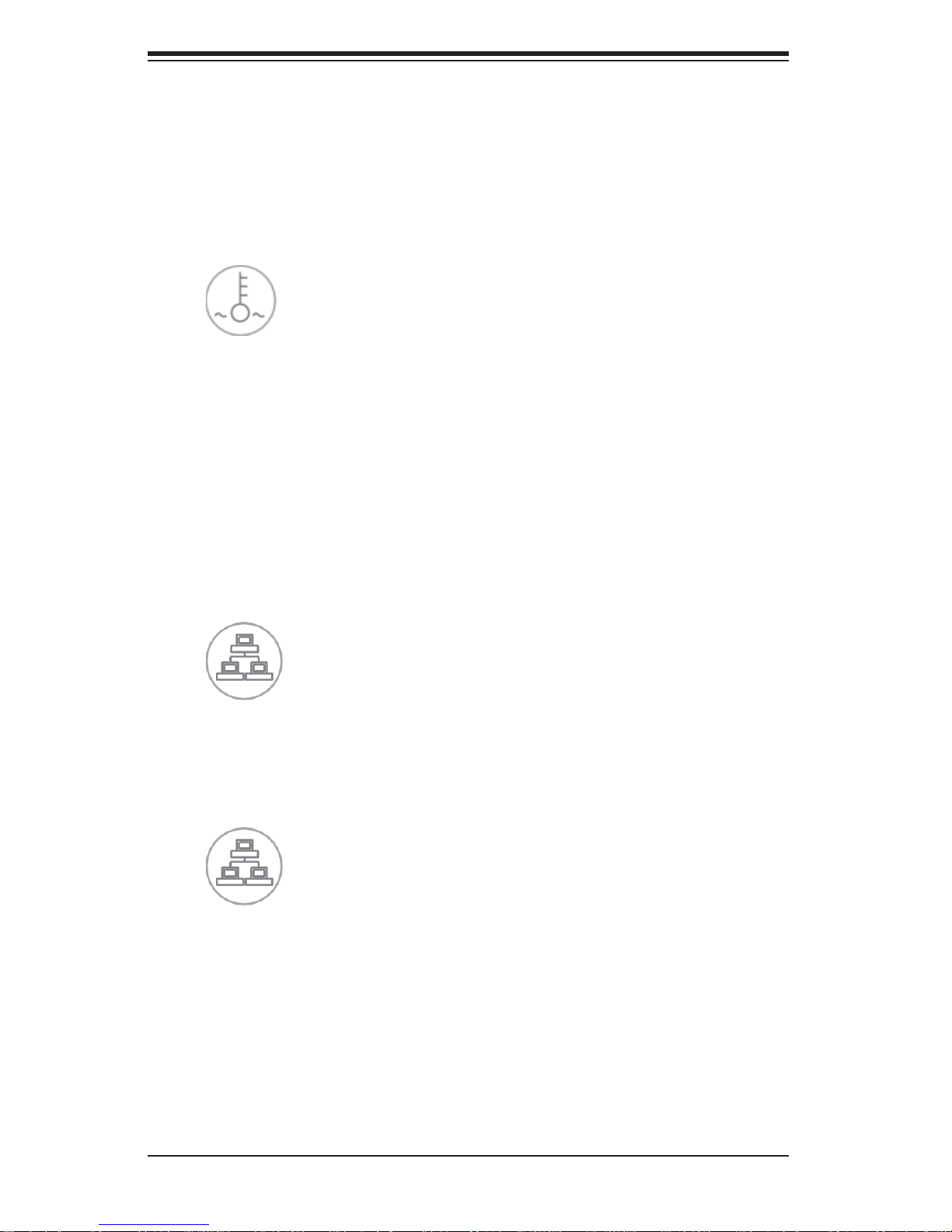
Overheat/Fan Fail LED
When this L ED fl ashes it indicates a fan failure. When continuously on (not fl ashing)
it indicates an overheat condition, which may be caused by cables obstructing the
airfl ow in the system or t he ambi ent room te mperat ure bein g too war m.
Check t he r ou ti ng o f th e c a bl es a nd m ake sur e al l fa ns a re p re se nt an d op e rat in g
normally. Y ou should also check to make sure that the chassis covers are installed.
Finally, verify that the heatsinks are installed properly. This LED will remain fl ashing
or on as long as the overheat condition exists.
2
NIC2
Indicates network activity on LAN2 when fl ashing.
1
NIC1
Indicates network activity on LAN1 when fl ashing.
3-2
Chapter 3: System Interface
HDD
Channel activity for all HDDs. This light indicates SATA drive activity on the 5018AMLTN4 when fl ashing.
Power
Indicates power is being supplied to the system's power supply units. This LED
should normally be illuminated when the system is operating.
3-4 SATA Drive Carrier LEDs
Each drive carrier has two LEDs.
• Green: When ill uminated, the green LED on the dri ve carrier i ndicates dri ve
activ ity. A connecti on to the backp lane enables t his LED to blink on an d off
when that particular drive is being accessed.
• Red: The red LED to indicate a drive failure. If one of the drives fails, you should
be notifi ed by your system management software. Please refer to Chapter 6 for
instructions on replacing failed drives.
3-3

SUPERSERVER 5018A-MLTN4 User's Manual
Notes
3-4
 Loading...