

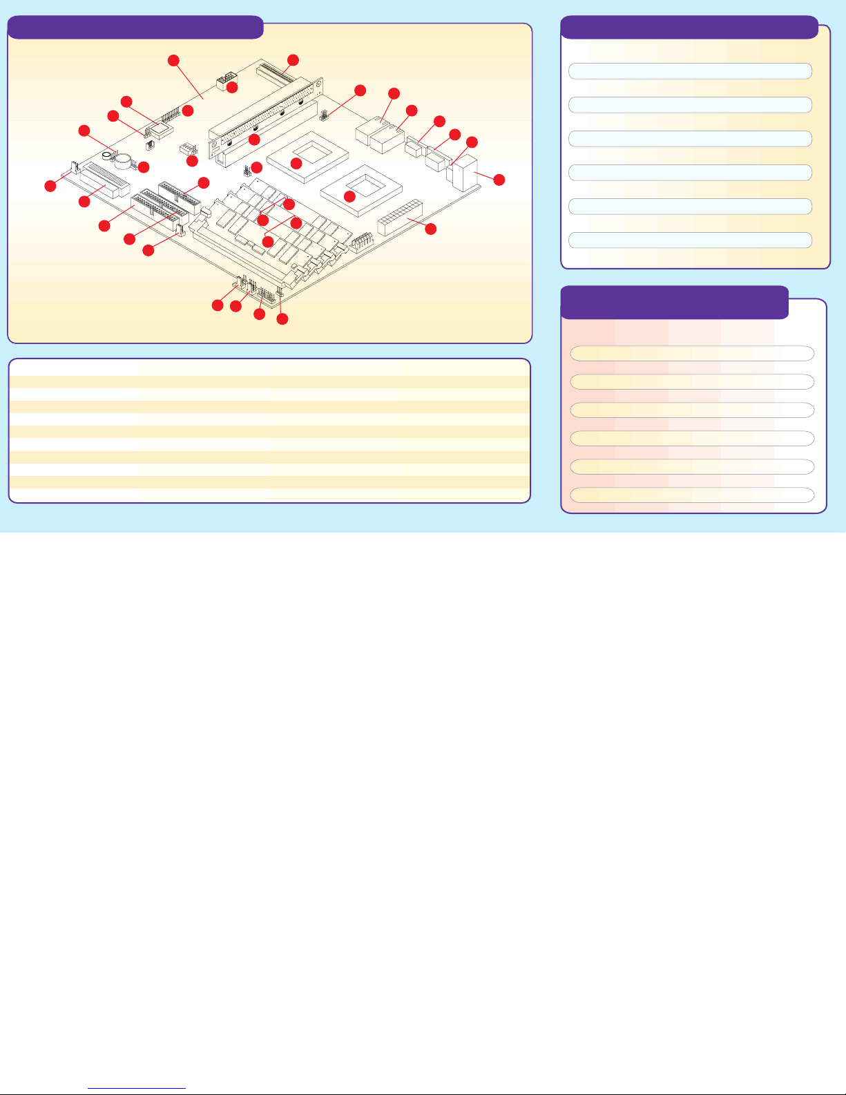
Motherboard Components
370DER+ Quick Reference
1
2
4
5
6
7
8
9
10
11
12
1 System Board
2 COM2 Header
3 SCSI Termination
4 BIOS Chip
5 JP57
6 JP56 on Board Speaker Disable/Enable
7 JBT1
8 Overheat Fan Header
9 Ultra160 LVD SCSI Ch A
10 IDE #1 connector
11 IDE #2 connector
Note: Interleaved ECC registered memory type must be installed in pairs: 17,18 and 19 , 20 especially.
*
3
31
32
13
14
12 Chassis Fan
13 Chassis Fan
14 OH Fan
15 JF1 Control Panel Header
16 Power LED Header
17,18 * Bank 0 Memory Modules
19,20 * Bank 1 Memory Modules
21 Primary Power Connector
22 Mouse and Keyboard connectors
23 2 USB ports
24 COM1 header
29
28
30
34
33
17
18
19
20
15
16
35
25 VGA header
26 LAN1
27 LAN2
28 Onbard VGA (Disable/Enable) JP60,61
29 Ultra160 LVD SCSI Ch B
30 PCI Riser Card
31 SW1
32 Floppy connector
33 JP1, JP3 header
34 CPU#2 Socket
35 CPU#1 Socket
Jumpers Description Default Setting
JA2 LVD SCSI Ch A Term. Open (Enabled)
27
26
25
24
23
JA4 LVD SCSI Ch B Term. Open (Enabled)
JBT1 CMOS Clear Pin 1-2 (Normal)
JP1 FSB Speed Setting Open (133 MHz)
JP56 Speaker Enble/Disble On (Enabled)
JP57 BIOS Select Pin 1-2 (BIOS1)
22
JP58 LAN1 Enable/Disable Off (Enabled)
JP60 VGA Enable/Disable Pin 2-3 (Enabled)
JP61 VGA Interrupt Enable Pin 2-3 (Enabled)
21
JP62 LAN2 Enable/Disable Off (Enabled)
JP63 Chipset Speed Setting Off (133 MHz)
JP64 SCSI Enable/Disable Pin 1-2 (Enabled)
CPU Core/Bus Ratio Selection
(DIP Switch 1)
CPU Core/
Bus Ratio
4.0
4.5
5.0
5.5
6.0
6.5
7.0
7.5
8.0
8.5
9.0
SW1
#4
ON
ON
ON
ON
OFF
OFF
OFF
OFF
OFF
OFF
OFF
SW1
OFF
OFF
OFF
OFF
OFF
OFF
OFF
#3
ON
ON
ON
ON
SW1
#2
ON
ON
OFF
OFF
ON
ON
OFF
OFF
ON
ON
OFF
SW1
#1
ON
OFF
ON
OFF
ON
OFF
ON
OFF
ON
OFF
ON
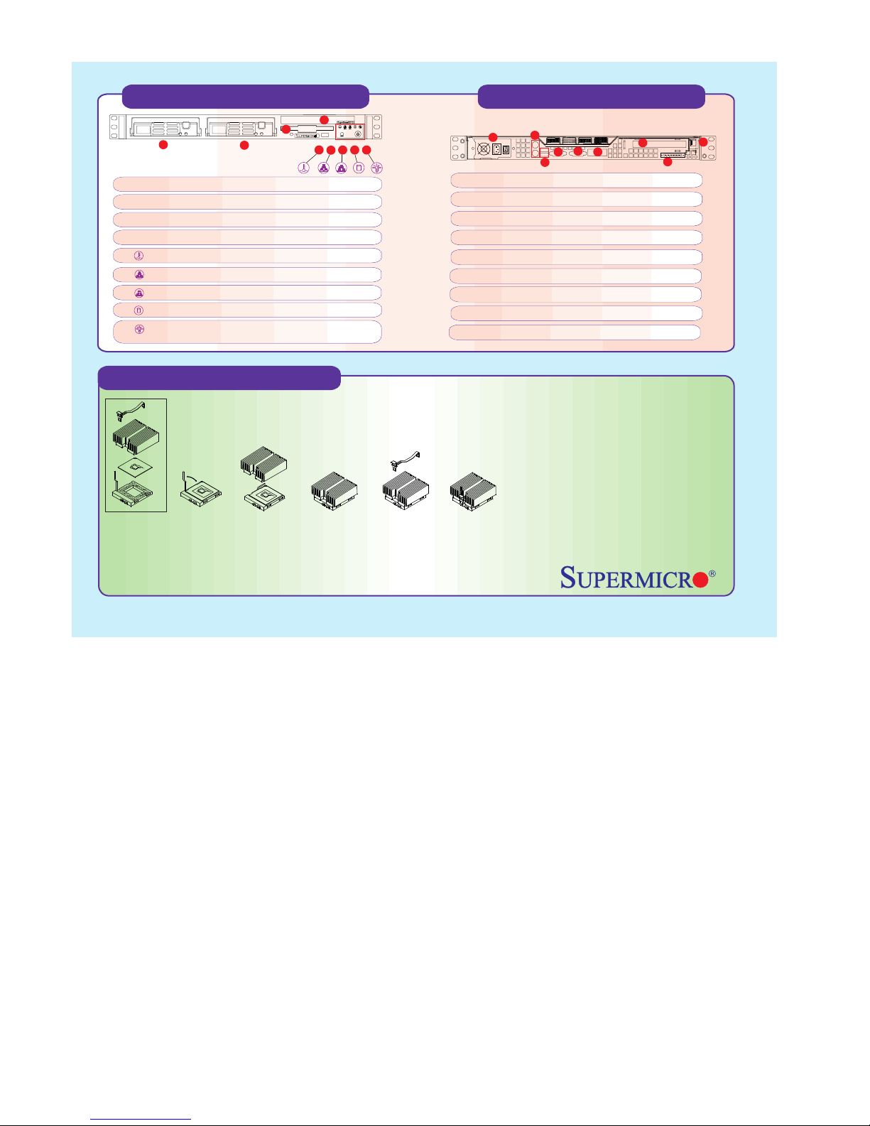
Front Panel Functions
3
4
1
1. Hot-plug SCSI hard drive, SCSI ID 0
2. Hot-plug SCSI hard drive, SCSI ID 1
3. CD-ROM/disketle drive assembly
4. Floopy Drive
5. Overheat: Indicates an overheat condition in the system
6. NIC2: Indicates network activity on LAN2 when flashing
7. NIC1: Indicates network activity on LAN1 when flashing
8. HDD: Indicates IDE channel activity.
9. Power: Indicates power is being supplied to the system's
power supply units
2
5
789
6
Rear Panel Functions
1
1. AC Power connector
2. PS/2 mouse and Keyboard port
3. 2 USB ports
4. 2 COM ports ( 1 internal)
5. 1 VGA port
6. 2 x Intel 82559 LAN port
7. 64/32-bit Expansion slot
8. External Ultra160 SCSI Connector
9. PCI Card Release Latch
Cooling Fan Installation
= >
1 2 3 4 5
1) Only those CPU heat sinks that are provided by Supermicro should be used.
2) Apply proper amount of silicon compound on the CPU's die.
3) Place the CPU heat sink on top of the CPU.
4) Place the heat sink spring on top of the CPU heat sink and lock the backside of the spring into its notch.
5) Lock the front side of the heat sink spring into its notch.
2
5
4
3
6
7
9
8
Warning !
CPU Heat Sink Installation Procedures
(For Supermicro SuperServer 1U Systems)
Due to the fact that adequate air flow and
proper thermal control are very critical in
maintaining 1U system's stability and
performance, it is imperative that the proper
installation procedures listed below be
followed in order to maximize system
performance. This is especially critical for 1U
Dual Processor Servers with speeds of 1
GHz and above.
To protect the system and components, it is essential that you reinstall the top panel after you have finished working on the system.
 Loading...