

Page 1

®
SUPERSERVER
1027R-73DAF
SUPER
USER’S MANUAL
1.0
Page 2

The information in this User’s Manual has been carefully reviewed and is believed to be accurate.
The vendor assumes no responsibility for any inaccuracies that may be contained in this document,
makes no commitment to update or to keep current the information in this manual, or to notify any
person or organization of the updates. Please Note: For the most up-to-date version of this
manual, please see our web site at
www.supermicro.com.
Super Micro Computer, Inc. ("Supermicro") reserves the right to make changes to the product
described in this manual at any time and without notice. This product, including software and documentation, is the property of Supermicro and/or its licensors, and is supplied only under a license.
Any use or reproduction of this product is not allowed, except as expressly permitted by the terms
of said license.
IN NO EVENT WILL SUPERMICRO BE LIABLE FOR DIRECT, INDIRECT, SPECIAL, INCIDENTAL,
SPECULATIVE OR CONSEQUENTIAL DAMAGES ARISING FROM THE USE OR INABILITY TO
USE THIS PRODUCT OR DOCUMENTATION, EVEN IF ADVISED OF THE POSSIBILITY OF
SUCH DAMAGES. IN PARTICULAR, SUPERMICRO SHALL NOT HAVE LIABILITY FOR ANY
HARDWARE, SOFTW ARE, OR DA TA STORED OR USED WITH THE PRODUCT, INCLUDING THE
COSTS OF REPAIRING, REPLACING, INTEGRATING, INSTALLING OR RECOVERING SUCH
HARDWARE, SOFTWARE, OR DATA.
Any disputes arising between manufacturer and customer shall be governed by the laws of Santa
Clara County in the State of California, USA. The State of California, County of Santa Clara shall
be the exclusive venue for the resolution of any such disputes. Super Micro's total liability for all
claims will not exceed the price paid for the hardware product.
FCC Statement: This equipment has been tested and found to comply with the limits for a Class A
digital device pursuant to Part 15 of the FCC Rules. These limits are designed to provide reasonable
protection against harmful interference when the equipment is operated in a commercial environment. This equipment generates, uses, and can radiate radio frequency energy and, if not installed
and used in accordance with the manufacturer’s instruction manual, may cause harmful interference
with radio communications. Operation of this equipment in a residential area is likely to cause harmful
interference, in which case you will be required to correct the interference at your own expense.
California Best Management Practices Regulations for Perchlorate Materials: This Perchlorate warning applies only to products containing CR (Manganese Dioxide) Lithium coin cells. “Perchlorate
Material-special handling may apply. See
www.dtsc.ca.gov/hazardouswaste/perchlorate”
WARNING: Handling of lead solder materials used in this
product may expose you to lead, a chemical known to the
State of California to cause birth defects and other reproductive harm.
Manual Revision 1.0
Release Date: December 18, 2012
Unless you request and receive written permission from Super Micro Computer, Inc., you may not
copy any part of this document.
Information in this document is subject to change without notice. Other products and companies
referred to herein are trademarks or registered trademarks of their respective companies or mark
holders.
Copyright © 2012 by Super Micro Computer, Inc.
All rights reserved.
Printed in the United States of America
Page 3

iii
Preface
Preface
About This Manual
This manual is written for professional system integrators and PC technicians. It
provides information for the installation and use of the SuperServer 1027R-73DAF.
Installation and maintainance should be performed by experienced technicians only .
The SuperServer 1027R-73DAF is a high-end server based on the SC1 13TQ-563CB
1U rackmountable chassis and the X9DRD-7LN4F dual processor serverboard.
Manual Organization
Chapter 1: Introduction
The fi rst chapter provides a checklist of the main components included with the
server system and describes the main features of the X9DRD-7LN4F serverboard
and the SC113TQ-563CB chassis.
Chapter 2: Server Installation
This chapter describes the steps necessary to install the SuperServer 1027R-73DAF
into a rack and check out the server confi guration prior to powering up the system.
If your server was ordered without processor and memory components, this chapter
will refer you to the appropriate sections of the manual for their installation.
Chapter 3: System Interface
Refer here for details on the system interface, which includes the functions and
information provided by the control panel on the chassis as well as other LEDs
located throughout the system.
Chapter 4: System Safety
You should thoroughly familiarize yourself with this chapter for a general overview
of safety precautions that should be followed when installing and servicing the
SuperServer 1027R-73DAF.
Page 4

SUPERSERVER 1027R-73DAF User's Manual
iv
Chapter 5: Advanced Serverboard Setup
Chapter 5 provides detailed information on the X9DRD-7LN4F serverboard, including the locations and functions of connections, headers and jumpers. Refer
to this chapter when adding or removing processors or main memory and when
reconfi guring the serverboard.
Chapter 6: Advanced Chassis Setup
Refer to Chapter 6 for detailed information on the SC113TQ-563CB server chassis.
You should follow the procedures given in this chapter when installing, removing
or reconfi guring SAS/SATA or peripheral drives and when replacing system power
supply units and cooling fans.
Chapter 7: BIOS
The BIOS chapter includes an introduction to BIOS and provides detailed information on running the CMOS Setup Utility.
Appendix A: BIOS Error Beep Codes
Appendix B: System Specifi cations
Page 5

Notes
Preface
v
Page 6

vi
Table of Contents
Chapter 1 Introduction
1-1 Overview .........................................................................................................1-1
1-2 Serverboard Features .....................................................................................1-2
Processors ......................................................................................................1-2
Memory ...........................................................................................................1-2
SAS .................................................................................................................1-2
Serial ATA ........................................................................................................1-2
PCI Expansion Slots ....................................................................................... 1-2
Rear I/O Ports ................................................................................................. 1-3
1-3 Server Chassis Features ................................................................................1-3
System Power ................................................................................................. 1-3
Control Panel .................................................................................................. 1-3
Cooling System ............................................................................................... 1-3
1-4 Contacting Supermicro ....................................................................................1-5
Chapter 2 Server Installation
2-1 Overview .........................................................................................................2-1
2-2 Unpacking the System .................................................................................... 2-1
2-3 Preparing for Setup .........................................................................................2-1
Choosing a Setup Location .............................................................................2-1
2-4 Warnings and Precautions .............................................................................. 2-2
Rack Precautions ............................................................................................ 2-2
Server Precautions ..........................................................................................2-2
Rack Mounting Considerations .......................................................................2-3
Ambient Operating Temperature ................................................................ 2-3
Reduced Airfl ow .........................................................................................2-3
Mechanical Loading ................................................................................... 2-3
Circuit Overloading .....................................................................................2-3
Reliable Ground ......................................................................................... 2-3
2-5 Installing the System into a Rack ................................................................... 2-4
Identifying the Sections of the Rack Rails ...................................................... 2-4
Inner Rails ....................................................................................................... 2-5
Outer Rails ......................................................................................................2-6
Installing the Server into a Telco Rack ........................................................... 2-9
Chapter 3 System Interface
3-1 Overview .........................................................................................................3-1
3-2 Control Panel Buttons ..................................................................................... 3-1
Reset ...............................................................................................................3-1
SUPERSERVER 1027R-73DAF User's Manual
Page 7

vii
Power ..............................................................................................................3-1
UID ..................................................................................................................3-1
3-3 Control Panel LEDs ........................................................................................3-2
Information LED ..............................................................................................3-2
NIC1 ................................................................................................................3-3
NIC2 ................................................................................................................3-3
HDD .................................................................................................................3-3
Power ..............................................................................................................3-3
3-4 Hard Drive Carrier LEDs ................................................................................. 3-4
Chapter 4 Standardized Warning Statements for AC Systems
4-1 About Standardized Warning Statements .......................................................4-1
Warning Defi nition ...........................................................................................4-1
Installation Instructions ....................................................................................4-4
Circuit Breaker ................................................................................................ 4-5
Power Disconnection Warning ........................................................................ 4-6
Equipment Installation ..................................................................................... 4-8
Restricted Area ................................................................................................ 4-9
Battery Handling ............................................................................................4-10
Redundant Power Supplies ..........................................................................4-12
Backplane Voltage ........................................................................................ 4-13
Comply with Local and National Electrical Codes ........................................ 4-14
Product Disposal ........................................................................................... 4-15
Hot Swap Fan Warning ................................................................................. 4-16
Power Cable and AC Adapter ...................................................................... 4-18
Chapter 5 Advanced Serverboard Setup
5-1 Handling the Serverboard ............................................................................... 5-1
Precautions .....................................................................................................5-1
Unpacking .......................................................................................................5-1
5-2 Connecting Cables .......................................................................................... 5-2
Connecting Data Cables ................................................................................. 5-2
Connecting Power Cables ..............................................................................5-2
Connecting the Control Panel ......................................................................... 5-2
5-3 Rear I/O Ports ................................................................................................. 5-3
5-4 Installing the Processor and Heatsink ............................................................ 5-4
Installing an LGA 2011 Processor ................................................................... 5-4
Installing a Passive CPU Heatsink ................................................................. 5-7
Removing the Heatsink ................................................................................... 5-7
5-5 Installing Memory ............................................................................................5-8
Table of Contents
Page 8

viii
SUPERSERVER 1027R-73DAF User's Manual
Memory Support .............................................................................................. 5-8
DIMM Installation ............................................................................................ 5-8
5-6 Adding PCI Add-On Cards ............................................................................ 5-12
5-7 Serverboard Details ...................................................................................... 5-13
X9DRD-7LN4F Quick Reference ..................................................................5-14
5-8 Connector Defi nitions ................................................................................... 5-16
5-9 Jumper Settings ............................................................................................ 5-23
5-10 Onboard Indicators ........................................................................................5-25
5-11 SATA and SAS Ports .....................................................................................5-26
5-12 Installing Software ......................................................................................... 5-27
SuperDoctor III .............................................................................................. 5-28
5-13 Onboard Battery ............................................................................................ 5-30
Chapter 6 Advanced Chassis Setup
6-1 Static-Sensitive Devices ..................................................................................6-1
Precautions .....................................................................................................6-1
6-2 Control Panel ..................................................................................................6-2
6-3 System Cooling ...............................................................................................6-2
System Fan Failure .........................................................................................6-2
6-4 Drive Bay Installation/Removal .......................................................................6-4
Accessing the Drive Bays ...............................................................................6-4
Hard Drive Installation ..................................................................................... 6-4
DVD Drive Installation ..................................................................................... 6-6
6-5 Power Supply ..................................................................................................6-8
Chapter 7 BIOS
7-1 Introduction ......................................................................................................7-1
Starting BIOS Setup Utility .............................................................................. 7-1
How To Change the Confi guration Data .........................................................7-2
Starting the Setup Utility ................................................................................. 7-2
7-2 Main Setup ...................................................................................................... 7-2
7-3 Advanced Setup Confi gurations......................................................................7-4
7-4 Event Logs .................................................................................................... 7-25
7-5 IPMI ............................................................................................................... 7-27
7-6 Boot ............................................................................................................... 7-29
7-7 Secur ity .........................................................................................................7-30
7-8 Save & Exit ................................................................................................... 7-31
Appendix A BIOS Error Beep Codes
Appendix B System Specifi cations
Page 9

Chapter 1
Introduction
1-1 Overview
The SuperServer 1027R-73DAF is a high-end server comprised of two main subsystems: the SC113TQ-563CB 1U server chassis and the X9DRD-7LN4F dual
processor serverboard. Please refer to our web site for information on operating
systems that have been certifi ed for use with the system (www.supermicro.com).
In addition to the serverboard and chassis, various hardware components have
been included with the 1027R-73DAF, as listed below:
• Six 4-cm counter-rotating fans (FAN-0086L4)
• Two passive CPU heatsinks (SNK-P0047PS)
• One air shroud (MCP-310-19010-0N)
• One riser card (RSC-RR1U-E8)
• SATA Accessories
One SATA backplane (BPN-SAS-113TQ)
Eight drive carriers (MCP-220-00047-0B)
• One rackmount kit (MCP-290-00043-0N)
Note: a complete list of safety warnings is provided on the Supermicro web site at
http://www.supermicro.com/about/policies/safety_information.cfm
Chapter 1: Introduction
1-1
Page 10

1-2
SUPERSERVER 1027R-73DAF User's Manual
1-2 Serverboard Features
At the heart of the SuperServer 1027R-73DAF lies the X9DRD-7LN4F, a dual
processor serverboard based on the Intel C602J chipset and designed to provide
maximum performance. Below are the main features of the X9DRD-7LN4F. (See
Figure 1-1 for a block diagram of the chipset).
Processors
The X9DRD-7LN4F supports single or dual Intel® Xeon E5-2600 Series processors
in LGA 2011 sockets (Socket R). Please refer to the serverboard description pages
on our web site for a complete listing of supported processors (www.supermicro.
com).
Memory
The X9DRD-7LN4F has 16 DIMM slots that can support up to 512 GB of RDIMM,
ECC LRDIMM or ECC/non-ECC UDIMM DDR3-1600/1333/1066/800 type memory.
See Chapter 5 for details.
SAS
A total of eight SAS 2.0 ports are provided with an LSI 2308 SAS controller. RAID
levels 0, 1, and 10 are supported.
Note: The operati ng system yo u use must h ave R AID su ppor t to e nable t he hotswap capability and RAI D function of the SAS drives.
Serial ATA
A SATA controller is also integrated into the chipset to provide two SATA 3.0 (6/
Gbps) and four SATA 2.0 (3 Gbps) ports, which are RAID 0, 1, 5 and 10 supported.
The SATA drives are hot-swappable units.
Note: The operati ng system yo u use must h ave R AID su ppor t to e nable t he hotswap capability and RAI D function of the SATA drives.
PCI Expansion Slots
The X9DR D-7LN4F has six PCI-E 3.0 x8 slots. One PCI slot may be used with the
riser card provided with the system. PCI slots are controlled by CPUs: both CPUs
must be installed to utilize all slots. See Chapter 5 for details.
Page 11

1-3
Chapter 1: Introduction
Rear I/O Ports
The color-coded I/O ports include one COM port, a VGA port, four USB 2.0 ports
(additional USB headers are included on the serverboard) and four 1 Gb Ethernet
ports. A dedicated IPMI LAN port is also included.
1-3 Server Chassis Features
The 1027R-73DAF features eight 2.5" hard drive bays and a redundant, higheffi ciency power supply. Details on the chassis and on servicing procedures can
be found in Chapter 6. The following is a general outline of the main features of
the chassis.
System Power
The 1027R-73DAF features one 560W power supply. The system needs to be shut
down when removing or replacing the power supply module.
Control Panel
The control panel provides important system monitoring and control information.
LEDs indicate power on, network activity, hard disk drive activity and a UID (Universal Information) LED. Also present are a main power button, a system reset
button and a UID button.
Cooling System
The 1027R-73DAF chassis' revolutionary cooling design has been optimized to
provide suffi cient cooling for dual CPU confi gurations. The chassis includes an
air shroud and six 4-cm counter-rotating fans located in the middle of the chassis.
System fan speed is based on temperature and controlled by IPMI.
Page 12
1-4
SUPERSERVER 1027R-73DAF User's Manual
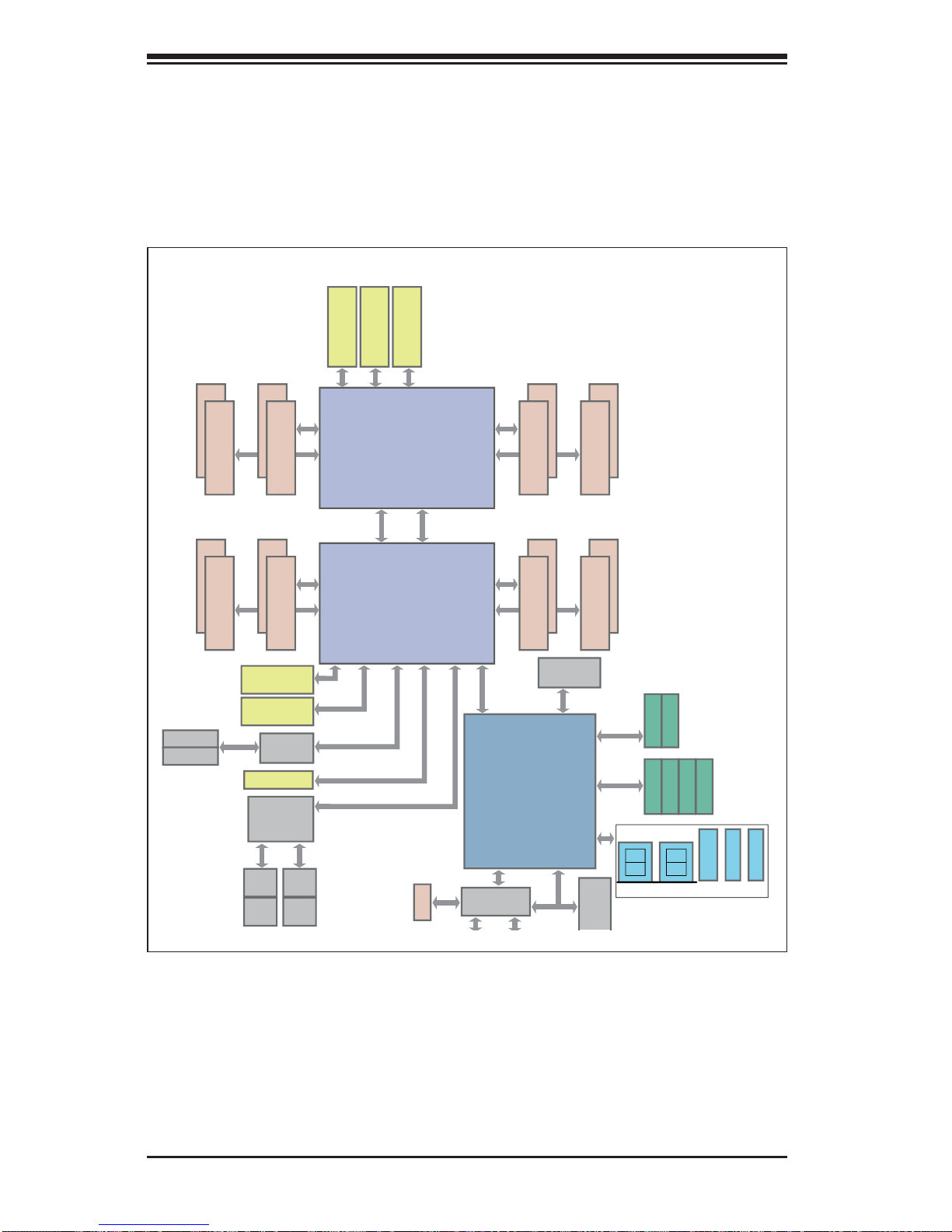
Figure 1-1. Intel C602J Chipset:
System Block Diagram
Note: This is a general block diagram. Please see Chapter 5 for details.
J23 SLOT#3
PCIE 3.0 x8
J24 SLOT#4
PCIE 3.0 x8
J25 SLOT#5
PCIE 3.0 x8
P0 P1
PE2
(AB)
PE2
(CD)
PE1
(AB)
DMI
DDR3 DIMM
CPU REAR
PROCESSOR
SANDYBRIDGE
PROCESSOR
SANDYBRIDGE
F
E
Socket 01
#2
#1
DDR3 DIMM
#2
#1
PE3
J22 SLOT#2
PCIE 3.0 x8
PCIE 3.0 x8
PCIE 3.0 x8
PCIE 3.0 x4
SAS
LSI
LAN1
LAN2
RJ45 RJ45
LAN3 LAN4
RJ45 RJ45
SAS2308
Powerville
I350-AM4
Quad GLAN
J26 SLOT#6
L-SAS0~3
L-SAS4~7
J21 SLOT#1
PCIE 3.0 x8
DDR3 DIMM
H
G
#2
#1
DDR3 DIMM
#2
#1
P1 P0
PE2
(AB)
PE2
(CD) (AB) (CD)
PE1
(AB)
PE3
DMI
PCH C602J
BIOS
SATA
SPI
SATA Gen3
6Gbps
SATA Gen3
6Gbps
SATA
SATA [0..1]
SCU0
USB
LPCPCI 32
SPI FLASH
DDR3 DIMM
CPU FRONT
D
C
Socket 00
#2
#1
#2
#1
PE3
DDR3 DIMM
B
A
#2
#1
DDR3 DIMM
QPI
QPI
#2
#1
I-SATA0
I-SATA1
S-SATA0
S-SATA1
S-SATA2
S-SATA3
REAR
HDR 2X5
0,1
TYPE-A
REAR
2,3
4,5 6 8,9
HDR 2X5
TPM HD
R
Port 80
HERMON
WPCM450]
DDR3
DDR3 DIMM
Page 13

1-5
Chapter 1: Introduction
1-4 Contacting Supermicro
Headquarters
Address: Super Micro Computer, Inc.
980 Rock Ave.
San Jose, CA 95131 U.S.A.
Tel: +1 (408) 503-8000
Fax: +1 (408) 503-8008
Email: marketing@supermicro.com (General Information)
support@supermicro.com (Technical Support)
Web Site:
www.supermicro.com
Europe
Address: Super Micro Computer B.V.
Het Sterrenbeeld 28, 5215 ML
's-Hertogenbosch, The Netherlands
Tel: +31 (0) 73-6400390
Fax: +31 (0) 73-6416525
Email: sales@supermicro.nl (General Information)
support@supermicro.nl (Technical Support)
rma@supermicro.nl (Customer Support)
Asia-Pacifi c
Address: Super Micro Computer, Inc.
4F, No. 232-1, Liancheng Rd
Chung-Ho Dist., New Taipei City 235
Taiwan
Tel: +886-(2) 8226-3990
Fax: +886-(2) 8226-3991
Web Site:
www.supermicro.com.tw
Technical Support:
Email: support@supermicro.com.tw
Tel: +886-(2)-8226-3990
Page 14

1-6
SUPERSERVER 1027R-73DAF User's Manual
Notes
Page 15
Chapter 2: Server Installation
2-1
Chapter 2
Server Installation
2-1 Overview
This chapter provides a quick setup checklist to get your SuperServer 1027R-73DAF
up and running. Following these steps in the order given should enable you to have
the system operational within a minimum amount of time. This quick setup assumes
that server system has come to you with the processors and memory preinstalled.
If your system is not already fully integrated with a serverboard, processors, system
memory etc., please turn to the chapter or section noted in each step for details on
installing specifi c components.
2-2 Unpacking the System
Y ou should inspect the box the SuperServer 1027R-73DAF was shipped in and note
if it was damaged in any way. If the server itself shows damage you should fi le a
damage claim with the carrier who delivered it.
Decide on a suitable location for the rack unit that will hold the server. It should
be situated in a clean, dust-free area that is well ventilated. Avoid areas where
heat, electrical noise and electromagnetic fi elds are generated. You will also need
it placed near a grounded power outlet. Read the Rack and Server Precautions in
the next section.
2-3 Preparing for Setup
The box the SuperServer 1027R-73DAF was shipped in should include two sets of
rail assemblies, two rail mounting brackets and the mounting screws you will need to
install the system into the rack. Follow the steps in the order given to complete the
installation process in a minimum amount of time. Please read this section in its entirety before you begin the installation procedure outlined in the sections that follow.
Choosing a Setup Location
• Leave enough clearance in front of the rack to enable you to open the front door
completely (~25 inches) and approximately 30 inches of clearance in the back
of the rack to allow for suffi cient airfl ow and ease in servicing.This product is for
installation only in a Restricted Access Location (dedicated equipment rooms,
service closets and the like).
Page 16

2-2
SUPERSERVER 1027R-73DAF User's Manual
2-4 Warnings and Precautions
• This product is not suitable for use with visual display work place devices
acccording to §2 of the the German Ordinance for Work with Visual Display
Units.
Rack Precautions
• Ensure that the leveling jacks on the bottom of the rack are fully extended to
the fl oor with the full weight of the rack resting on them.
• In single rack installation, stabilizers should be attached to the rack. In multiple
rack installations, the racks should be coupled together.
• Always make sure the rack is stable before extending a component from the
rack.
• You should extend only one component at a time - extending two or more si-
multaneously may cause the rack to become unstable.
Server Precautions
• Review the electrical and general safety precautions in Chapter 4.
• Determine the placement of each component in the rack before you install the
rails.
• Install the heaviest server components on the bottom of the rack fi rst, and then
work up.
• Use a regulating uninterruptible power supply (UPS) to protect the server from
power surges, voltage spikes and to keep your system operating in case of a
power failure.
• Allow the hot plug drives and power supply modules to cool before touching
them.
• Always keep the rack's front door and all panels and components on the servers
closed when not servicing to maintain proper cooling.
Page 17
Chapter 2: Server Installation
2-3
Rack Mounting Considerations
Ambient Operating Temperature
If installed in a closed or multi-unit rack assembly, the ambient operating temperature of the rack environment may be greater than the ambient temperature of the
room. Therefore, consideration should be given to installing the equipment in an
environment compatible with the manufacturer’s maximum rated ambient temperature (Tmra).
Reduced Airfl ow
Equipment should be mounted into a rack so that the amount of airfl ow required
for safe operation is not compromised.
Mechanical Loading
Equipment should be mounted into a rack so that a hazardous condition does not
arise due to uneven mechanical loading.
Circuit Overloading
Consideration should be given to the connection of the equipment to the power
supply circuitry and the effect that any possible overloading of circuits might have
on overcurrent protection and power supply wiring. Appropriate consideration of
equipment nameplate ratings should be used when addressing this concern.
Reliable Ground
A reliable ground must be maintained at all times. To ensure this, the rack itself
should be grounded. Particular attention should be given to power supply connections other than the direct connections to the branch circuit (i.e. the use of power
strips, etc.).
Warning! To prevent bodily injury when mounting or servicing this unit in a
rack, you must take special precautions to ensure that the system remains
stable. The following guidelines are provided to ensure your safety:
• This unit should be mounted at the bottom of the rack if it is the only unit in
the rack.
• When mounting this unit in a partially fi lled rack, load the rack from the bottom
to the top with the heaviest component at the bottom of the rack.
• If the rack is provided with stabilizing devices, install the stabilizers before
mounting or servicing the unit in the rack.
Page 18

2-4
SUPERSERVER 1027R-73DAF User's Manual
2-5 Installing the System into a Rack
This section provides information on installing the SuperServer 1027R-73DAF into
a rack. If the system has already been mounted into a rack, you can skip ahead
to Sections 2-5 and 2-6. Note: This rail will fi t a rack between 26" and 33.5" deep.
There are a variety of rack units on the market, which may mean the assembly
procedure will differ slightly. The following is a guideline for installing the 1027R73DAF into a rack with the rack rails provided. You should also refer to the installation instructions that came with the rack unit you are using.
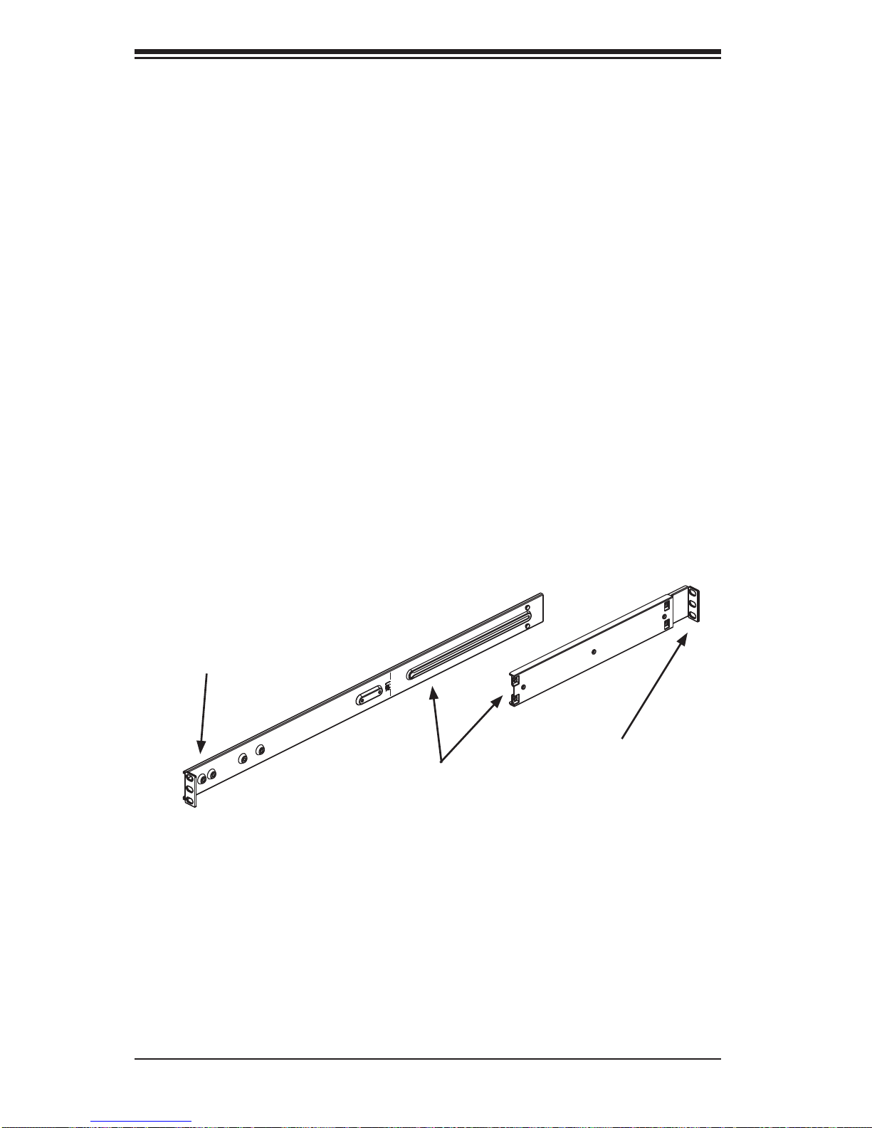
Identifying the Sections of the Rack Rails
Each assembly consists of two sections: an inner fi xed chassis rail that secures
directly to the server chassis and an outer fi xed rack rail that secures directly to
the rack itself.
Figure 2-1. Identifying the Sections of the Rack Rails
Rail Extension
(Inner rail is pre-installed)
Outer Rails
Page 19
Chapter 2: Server Installation
2-5
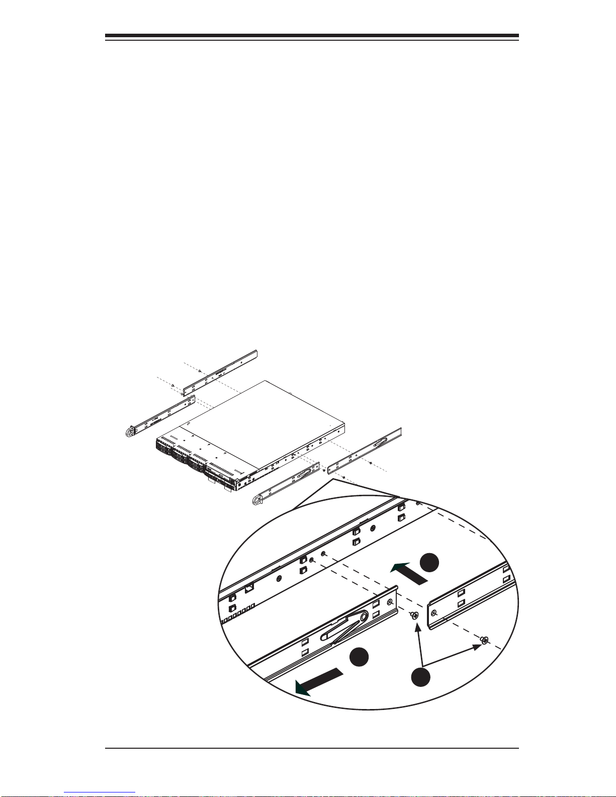
Figure 2-2. Installing Chassis Rails
Inner Rails
The SC1 13 chassis includes a set of inner rails in two sections: inner rails and inner
rail extensions. The inner rails are pre-attached and do not interfere with normal use
of the chassis if you decide not to use a server rack. Attach the inner rail extension
to stabilize the chassis within the rack.
Installing the Inner Rails (Figure 2-2)
1. Place the inner rack extensions on the side of the chassis aligning the hooks
of the chassis with the rail extension holes. Make sure the extension faces
"outward" just like the pre-attached inner rail.
2. Slide the extension toward the front of the chassis.
3. Secure the chassis with two screws as illustrated.
4. Repeat steps 1-3 for the other inner rail extension.
1
1
1
2
1
3
Page 20
2-6
SUPERSERVER 1027R-73DAF User's Manual
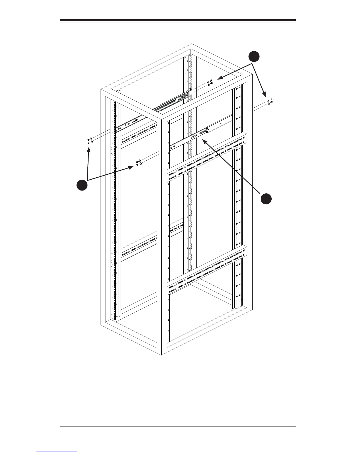
Outer Rails
Installing the Outer Rails to the Rack (Figures 2-3 and 2-4)
1. Attach the short bracket to the outside of the long bracket. You must align the
pins with the slides. Also, both bracket ends must face the same direction.
2. Adjust both the short and long brackets to the proper distance so that the rail
fi ts snugly into the rack.
3. Secure the long bracket to the front side of the outer rail with two M5 screws
and the short bracket to the rear side of the outer rail with three M5 screws.
4. Repeat steps 1-4 for the left outer rail.
Secure to the
Front of the Rack
Secure to the
Rear of the Rack
Figure 2-3. Assembling the Outer Rails
Attach Outer Racks
Together
Page 21
Chapter 2: Server Installation
2-7
Figure 2-4. Installing the Outer Rails to the Rack
1
2
1
3
1
3
Page 22
2-8
SUPERSERVER 1027R-73DAF User's Manual
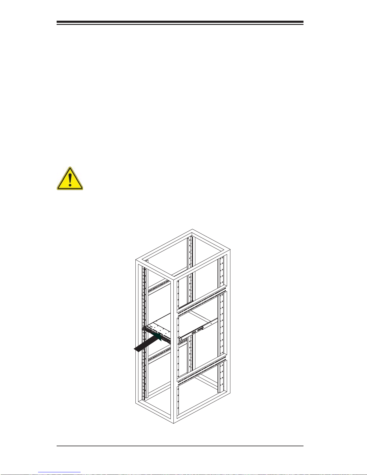
Figure 2-5. Installing the Server into a Rack
Installing the Chassis into a Rack (Figure 2-5)
1. Confi rm that chassis includes the inner rails and rail extensions . Also, confi rm
that the outer rails are installed on the rack.
2. Line chassis rails with the front of the rack rails.
3. Slide the chassis rails into the rack rails, keeping the pressure even on both
sides (you may have to depress the locking tabs when inserting). When the
server has been pushed completely into the rack, you should hear the locking
tabs "click".
4. (Optional) Insert and tightening the thumbscrews that hold the front of the
server to the rack.
Stability hazard. The rack stabilizing mechanism must be in place, or the
rack must be bolted to the fl oor before you slide the unit out for servicing.
Failure to stabilize the rack can cause the rack to tip over.
Note: fi gures are for illustrative purposes only. Always install servers into racks
from the bottom up.
Page 23
Chapter 2: Server Installation
2-9
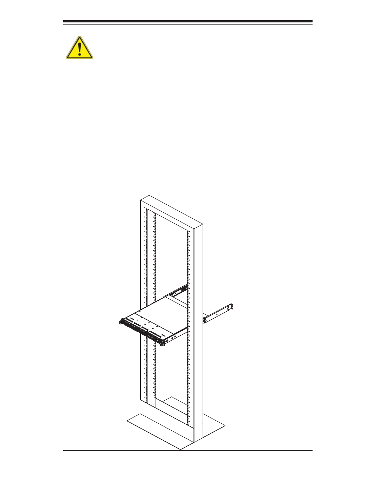
Warning: do not pick up the server with the front handles. They are designed
to pull the system from a rack only.
Installing the Server into a Telco Rack
To install the SuperServer 1027R-73DAF into a Telco type rack, use two L-shaped
brackets on either side of the chassis (four total). First, determine how far follow the
server will extend out the front of the rack. Larger chassis should be positioned to
balance the weight between front and back. If a bezel is included on your server,
remove it. Then attach the two front brackets to each side of the chassis, then the
two rear brackets positioned with just enough space to accommodate the width of
the telco rack. Finish by sliding the chassis into the rack and tightening the brackets
to the rack.
Note: these fi gures are for illustration puposes only. Always install servers to the
bottom of a rack fi rst.
Figure 2-6. Installing the Server into a Telco Rack
Page 24

2-10
SUPERSERVER 1027R-73DAF User's Manual
Notes
Page 25
Chapter 3: System Interface
3-1
Chapter 3
System Interface
3-1 Overview
There are several LEDs on the control panel to keep you constantly informed of the
overall status of the system as well as the three buttons described below.
3-2 Control Panel Buttons
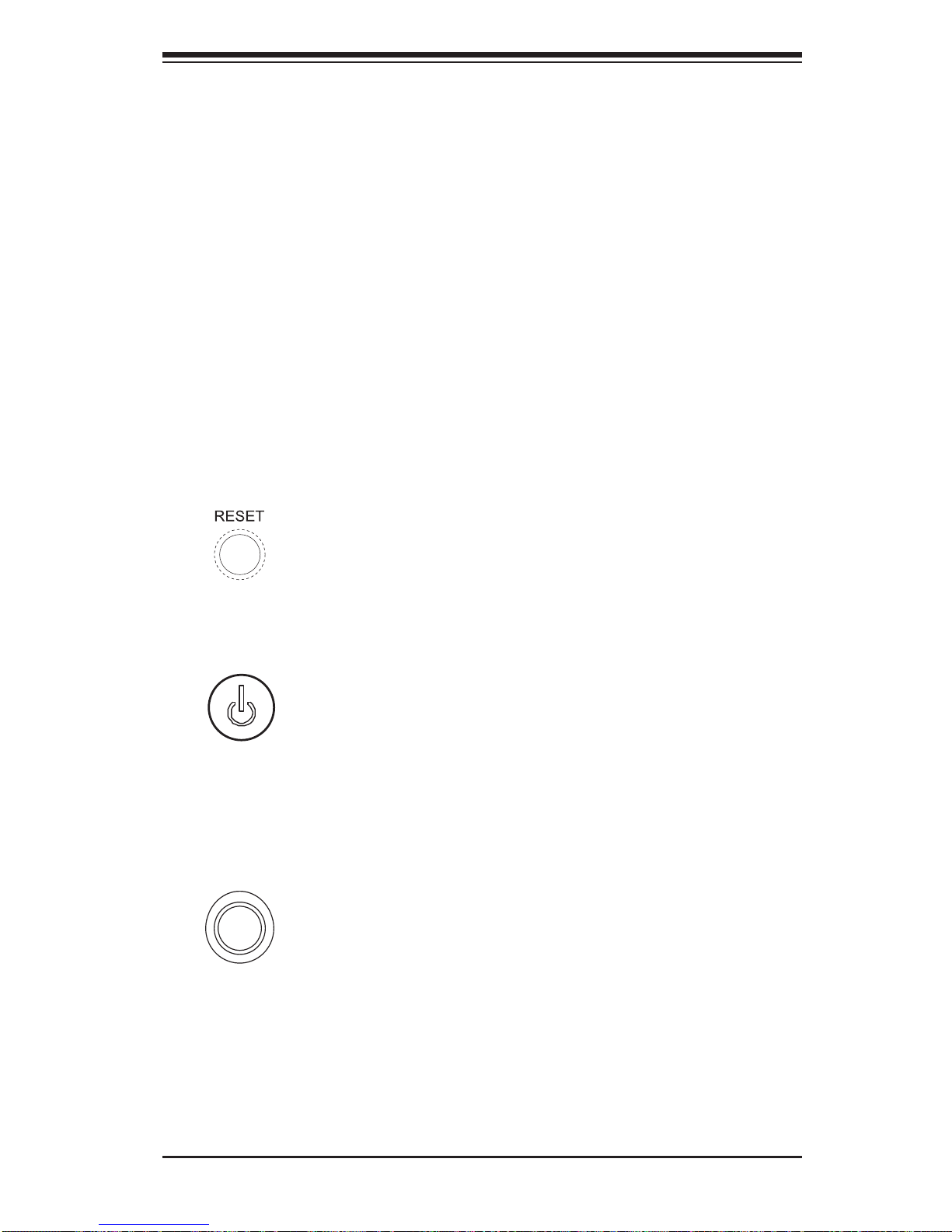
There are three buttons located on the front of the chassis: a reset button, a power
on/off button and a UID button.
Reset
Use the reset button to reboot the system.
Power
This is the main power button, which is used to apply or turn off the main system
power. T urning off system power with this button removes the main power but keeps
standby power supplied to the system.
UID
Depressing the UID (unit identifi er) button illuminates an LED on both the front
and rear of the chassis for easy system location in large stack confi gurations. The
LED will remain on until the button is pushed a second time. Another UID button
on the rear of the chassis serves the same function. See the table in Figure 3-1 for
descriptions of UID LED states.
Page 26
3-2
SUPERSERVER 1027R-73DAF User's Manual
3-3 Control Panel LEDs
The control panel located on the front of the SC1 13TQ chassis has fi ve LEDs. These
LEDs provide you with critical information related to different parts of the system.
This section explains what each LED indicates when illuminated and any corrective
action you may need to take.
Note: deactivating the UID LED must be performed in the same way it was activated.
(If the UID LED was activated via IPMI, you can only turn the LED off via IPMI and
not with the UID button.)
Information LED
This LED will be solid blue when the UID function has been activated. When this
LED fl ashes red, it indicates a fan failure. When red continuously it indicates an
overheat condition, which may be caused by cables obstructing the airfl ow in the
system or the ambient room temperature being too warm. Check the routing of
the cables and make sure all fans are present and operating normally. You should
also check to make sure that the chassis covers are installed. Finally, verify that
the heatsinks are installed properly (see Chapter 5). This LED will remain fl ashing
or on as long as the indicated condition exists.
Information LED States
State Indication
Continuously On (Red) An overheat condition has occured.
Fast Blinking Red (1 Hz) Fan Failure
Slow Blinking Red (.25 Hz) Power Fail
Solid Blue Local UID button has been activated.
Blinking Blue IPM/Remote UID has been activated
Page 27
Chapter 3: System Interface
3-3
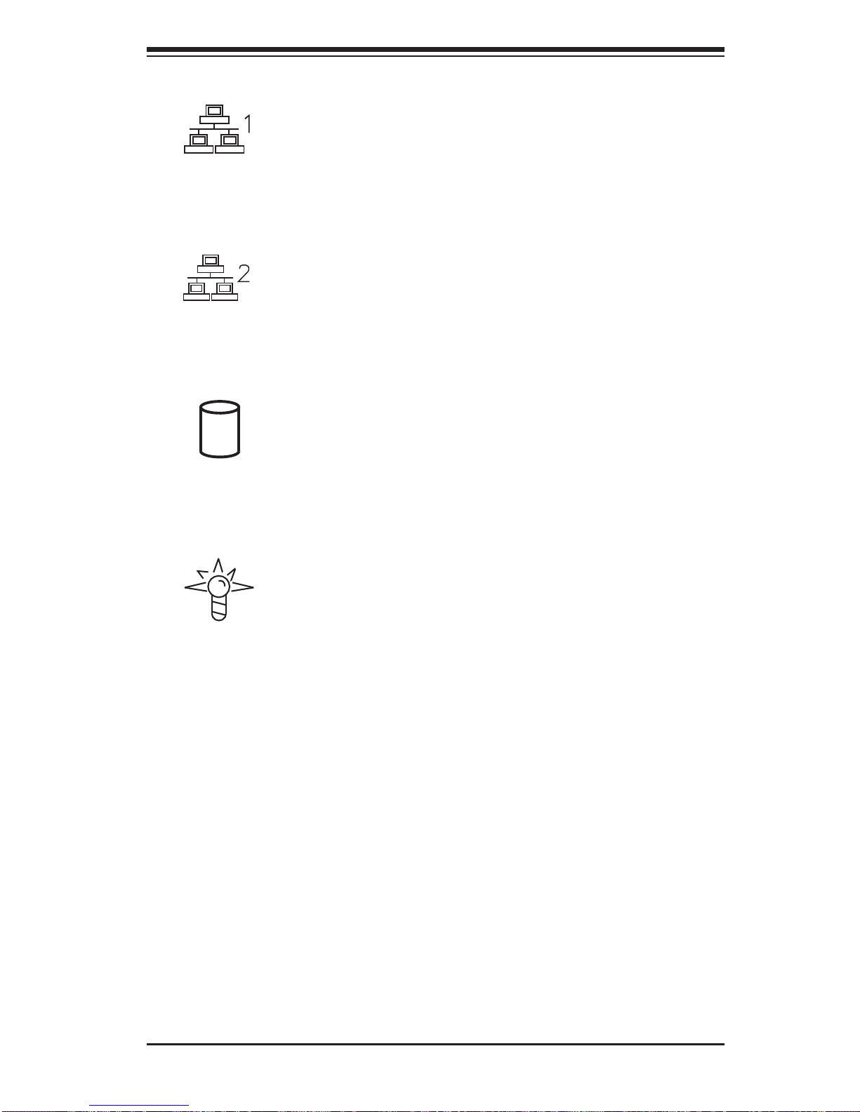
NIC1
Indicates network activity on LAN2 when fl ashing.
NIC2
Indicates network activity on LAN1 when fl ashing.
HDD
Indicates DVD-ROM/hard drive activity when fl ashing.
Power
Indicates power is being supplied to the system's power supply units. This LED
should normally be illuminated when the system is operating.
Page 28

3-4
SUPERSERVER 1027R-73DAF User's Manual
3-4 Hard Drive Carrier LEDs
Each hard drive carrier has two LEDs.
• Green: When illuminated, the green LED on the front of the drive carrier in-
dicates drive activity. A connection to the SATA backplane enables this LED to
blink on and off when that particular drive is being accessed.
• Red: The red LED indicates two states. When blinking, it indicates the drive
is rebuilding. When solid, it indicates a drive failure. If a drive fails, you should
be notifi ed by your system management software. Please refer to Chapter 6 for
instructions on replacing failed drives.
Page 29
4-1
Chapter 4: Warning Statements for AC Systems
Chapter 4
Standardized Warning Statements for AC Systems
4-1 About Standardized Warning Statements
The following statements are industry standard warnings, provided to warn the user
of situations which have the potential for bodily injury. Should you have questions
or experience difficulty, contact Supermicro's Technical Support department
for assistance. Only certifi ed technicians should attempt to install or confi gure
components.
Read this appendix in its entirety before installing or confi guring components in the
Supermicro chassis.
These warnings may also be found on our web site at http://www.supermicro.com/
about/policies/safety_information.cfm.
Warning!
This warning symbol means danger. You are in a situation that could cause bodily
injury. Before you work on any equipment, be aware of the hazards involved with
electrical circuitry and be familiar with standard practices for preventing accidents.
Warning Defi nition
警告の定義
この警告サインは危険を意味します。
人身事故につながる可能性がありますので、いずれの機器でも動作させる前に、
電気回路に含まれる危険性に注意して、標準的な事故防止策に精通して下さい。
此警告符号代表危险。
您正处于可能受到严重伤害的工作环境中。在您使用设备开始工作之前,必须充分
意识到触电的危险,并熟练掌握防止事故发生的标准工作程序。请根据每项警告结
尾的声明号码找到此设备的安全性警告说明的翻译文本。
此警告符號代表危險。
您正處於可能身體可能會受損傷的工作環境中。在您使用任何設備之前,請注意觸
電的危險,並且要熟悉預防事故發生的標準工作程序。請依照每一注意事項後的號
碼找到相關的翻譯說明內容。
Page 30

4-2
SUPERSERVER 1027R-73DAF User's Manual
Warnung
WICHTIGE SICHERHEITSHINWEISE
Dieses Warnsymbol bedeutet Gefahr. Sie befi nden sich in einer Situation, die zu
Verletzungen führen kann. Machen Sie sich vor der Arbeit mit Geräten mit den
Gefahren elektrischer Schaltungen und den üblichen Verfahren zur Vorbeugung
vor Unfällen vertraut. Suchen Sie mit der am Ende jeder Warnung angegebenen
Anweisungsnummer nach der jeweiligen Übersetzung in den übersetzten
Sicherheitshinweisen, die zusammen mit diesem Gerät ausgeliefert wurden.
BEWAHREN SIE DIESE HINWEISE GUT AUF.
INSTRUCCIONES IMPORTANTES DE SEGURIDAD
Este símbolo de aviso indica peligro. Existe riesgo para su integridad física. Antes
de manipular cualquier equipo, considere los riesgos de la corriente eléctrica y
familiarícese con los procedimientos estándar de prevención de accidentes. Al
fi nal de cada advertencia encontrará el número que le ayudará a encontrar el texto
traducido en el apartado de traducciones que acompaña a este dispositivo.
GUARDE ESTAS INSTRUCCIONES.
IMPORTANTES INFORMATIONS DE SÉCURITÉ
Ce symbole d'avertissement indique un danger. Vous vous trouvez dans une
situation pouvant entraîner des blessures ou des dommages corporels. Avant
de travailler sur un équipement, soyez conscient des dangers liés aux circuits
électriques et familiarisez-vous avec les procédures couramment utilisées pour
éviter les accidents. Pour prendre connaissance des traductions des avertissements
fi gurant dans les consignes de sécurité traduites qui accompagnent cet appareil,
référez-vous au numéro de l'instruction situé à la fi n de chaque avertissement.
CONSERVEZ CES INFORMATIONS.
ןונקת תורהצהאהרהז
ןה תואבה תורהצהא ינפמ שמתשמה תא ריהזהל תנמ לע ,היישעתה ינקת יפ לע תורהז הלבח
ה וא תולאש שיו הדימב .תירשפא תיזיפי ,יהשלכ היעבב תולקתרוציל שי הכימת תקלחמ םע רשק
רידגהל וא ןיקתהל םיאשר דבלב םיכמסומ םיאנכט .ורקימרפוס לש תינכט תאה .םיביכר
אורקל שי .ורקימרפוס יזראמב םיביכרה
תרדגה וא תנקתה ינפל ואולמב חפסנה תא
Page 31

4-3
Warning Statements for AC Systems
안전을 위한 주의사항
경고!
이 경고 기호는 위험이 있음을 알려 줍니다. 작업자의 신체에 부상을 야기 할 수
있는 상태에 있게 됩니다. 모든 장비에 대한 작업을 수행하기 전에 전기회로와
관련된 위험요소들을 확인하시고 사전에 사고를 방지할 수 있도록 표준
작업절차를 준수해 주시기 바랍니다.
해당 번역문을 찾기 위해 각 경고의 마지막 부분에 제공된 경고문 번호를
참조하십시오
BELANGRIJKE VEILIGHEIDSINSTRUCTIES
Dit waarschuwings symbool betekent gevaar. U verkeert in een situatie die
lichamelijk letsel kan veroorzaken. Voordat u aan enige apparatuur gaat werken,
dient u zich bewust te zijn van de bij een elektrische installatie betrokken risico's
en dient u op de hoogte te zijn van de standaard procedures om ongelukken te
voorkomen. Gebruik de nummers aan het eind van elke waarschuwing om deze te
herleiden naar de desbetreffende locatie.
BEWAAR DEZE INSTRUCTIES
. ﻲﻓ ﻚﻧﺍ ﻥﺃ ﻦﻜﻤﻳ ﺔﻟﺎﺣ ﻲﻓ ﺐﺒﺴﺘﺗ ﺔﺑﺎﺻﺍ ﺔﻳﺪﺴﺟ ﺰﻣﺮﻟﺍ ﺍﺬﻫ ﻲﻨﻌﻳ ﺮﻄﺧ !ﺮﻳﺬﺤﺗ
ﻥﺃ ﻞﺒﻗ ﻱﺃ ﻰﻠﻋ ﻞﻤﻌﺗ ﺕﺍﺪﻌﻣ،ﻛﻢﻠﻋ ﻰﻠﻋ ﻦ ﻦﻋ ﺔﻤﺟﺎﻨﻟﺍ ﺮﻁﺎﺨﻤﻟﺎﺑ ﺮﺋﺍﻭﺪﻟﺍ
ﺔﻴﺋﺎﺑﺮﻬﻜﻟﺍ
ﻛﻭﺔﻳﺍﺭﺩ ﻰﻠﻋ ﻦ ﺭﺎﻤﻤﻟﺎﺑﺕﺎﺳ ﺔﻴﺋﺎﻗﻮﻟﺍ ﻟ ﻊﻨﻤﻉﻮﻗﻭ ﻱﺃﺙﺩﺍﻮﺣ
ﻢﻗﺭ ﻡﺪﺨﺘﺳﺍ ﻥﺎﻴﺒﻟﺍ ﺹﻮﺼﻨﻤﻟﺍ ﺔﻳﺎﻬﻧ ﻲﻓ ﺮﻳﺬﺤﺗ ﻞﻛ ﺭﻮﺜﻌﻠﻟ ﺎﻬﺘﻤﺟﺮﺗ
Page 32

4-4
SUPERSERVER 1027R-73DAF User's Manual
Installation Instructions
Warning!
Read the installation instructions before connecting the system to the power source.
Warnung
Vor dem Anschließen des Systems an die Stromquelle die Installationsanweisungen
lesen.
¡Advertencia!
Lea las instrucciones de instalación antes de conectar el sistema a la red de
alimentación.
Attention
Avant de brancher le système sur la source d'alimentation, consulter les directives
d'installation.
設置手順書
システムを電源に接続する前に、設置手順書をお読み下さい。
ﻟﺍ ﺕﺍﺩﺎﺷﺭﺇ ﺮﻗﺍﺐﻴﻛﺮﺘ ﻞﻴﺻﻮﺗ ﻞﺒﻗ ﻰﻟﺇ ﻡﺎﻈﻨﻟﺍ ﺔﻗﺎﻄﻠﻟ ﺭﺪﺼﻣ
אורקל שי רוקמל תכרעמה רוביח ינפל הנקתה תוארוה תאחתמ.
시스템을 전원에 연결하기 전에 설치 안내를 읽어주십시오.
Waarschuwing
Raadpleeg de installatie-instructies voordat u het systeem op de voedingsbron
aansluit.
警告
将此系统连接电源前,请先阅读安装说明。
警告
將系統與電源連接前,請先閱讀安裝說明。
Page 33

4-5
Chapter 4: Warning Statements for AC Systems
Circuit Breaker
Warning!
This product relies on the building's installation for short-circuit (overcurrent)
protection. Ensure that the protective device is rated not greater than: 250 V, 20 A.
サーキット・ブレーカー
この製 品 は、短絡(過電流)保護装置がある建物での設置を前提としています。
保護装置の定格が250V、20Aを超えないことを確認下さい。
Warnung
Dieses Produkt ist darauf angewiesen, dass im Gebäude ein Kurzschluss-
bzw. Überstromschutz installiert ist. Stellen Sie sicher, dass der Nennwert der
Schutzvorrichtung nicht mehr als: 250 V, 20 A beträgt.
¡Advertencia!
Este equipo utiliza el sistema de protección contra cortocircuitos (o sobrecorrientes)
del edifi cio. Asegúrese de que el dispositivo de protección no sea superior a: 250
V, 20 A.
Attention
Pour ce qui est de la protection contre les courts-circuits (surtension), ce produit
dépend de l'installation électrique du local. Vérifi ez que le courant nominal du
dispositif de protection n'est pas supérieur à :250 V, 20 A.
לע ךמתסמ הז רצומנגהה תעינמל םינבמב תנקתומה יכ אדוול שי .ילמשח רצק
רצקה ינפמ ןגמה רישכמה ילמשחהמ רתוי אל אוה-250 V, 20 A
ﺞﺘﻨﻤﻟﺍ ﺍﺬﻫ ﻰﻠﻋ ﺪﻤﺘﻌﻳ ﺕﺍﺪﻌﻣ ﺔﻳﺎﻤﺤﻟﺍ ﺓﺮﻴﺼﻘﻟﺍﺮﺋﺍﻭﺪﻟﺍ ﻦﻣ ﺎﻬﺘﻴﺒﺜﺗ ﻢﺗ ﻲﺘﻟﺍ ﻲﻓ
ﻰﻨﺒﻤﻟﺍ
20A, 250V : ﻦﻣ ﺪﻛﺄﺗ ﻥﺃ ﻢﻴﻴﻘﺗ ﺯﺎﻬﺠﻟﺍ ﻟﺍﻲﺋﺎﻗﻮ ﺲﻴﻟ ﻦﻣ ﺮﺜﻛﺃ
警告
此产品的短路(过载电流)保护由建筑物的供电系统提供,确保短路保护设备的额定电
流不大于250V,20A。
警告
此產品的短路(過載電流)保護由建築物的供電系統提供,確保短路保護設備的額定電
流不大於250V,20A。
Page 34

4-6
SUPERSERVER 1027R-73DAF User's Manual
Power Disconnection Warning
電源切断の警告
システムコンポーネントの取り付けまたは取り外しのために、シャーシー内部にアクセス
するには、
システムの電源はすべてのソースから切断され、電源コードは電源モジュールから取り
外す必要があります。
警告
在你打开机箱并安装或移除内部器件前,必须将系统完全断电,并移除电源线。
警告
在您打開機殼安裝或移除內部元件前,必須將系統完全斷電,並移除電源線。
Warnung
Das System muss von allen Quellen der Energie und vom Netzanschlusskabel
getrennt sein, das von den Spg.Versorgungsteilmodulen entfernt wird, bevor es
auf den Chassisinnenraum zurückgreift, um Systemsbestandteile anzubringen oder
zu entfernen.
Warning!
The system must be disconnected from all sources of power and the power cord
removed from the power supply module(s) before accessing the chassis interior to
install or remove system components.
경고!
이 제품은 전원의 단락(과전류)방지에 대해서 전적으로 건물의 관련 설비에
의존합니다. 보호장치의 정격이 반드시 250V(볼트), 20A(암페어)를 초과하지
않도록 해야 합니다.
Waarschuwing
Dit product is afhankelijk van de kortsluitbeveiliging (overspanning) van
uw electrische installatie. Controleer of het beveiligde aparaat niet groter
gedimensioneerd is dan 220V, 20A.
Page 35

4-7
Chapter 4: Warning Statements for AC Systems
¡Advertencia!
El sistema debe ser disconnected de todas las fuentes de energía y del cable
eléctrico quitado de los módulos de fuente de alimentación antes de tener acceso
el interior del chasis para instalar o para quitar componentes de sistema.
Attention
Le système doit être débranché de toutes les sources de puissance ainsi que de
son cordon d'alimentation secteur avant d'accéder à l'intérieur du chassis pour
installer ou enlever des composants de systéme.
ילמשח קותינ ינפמ הרהזא
!הרהזא
למשחה תורוקמ לכמ תכרעמה תא קתנל שי ריסהל שיו קפסהמ ילמשחה לבכ תא
נקתה ךרוצל זראמה לש ימינפה קלחל השיג ינפלת רסה ואת .םיביכר
ﻞﺼﻓ ﺐﺠﻳ ﻡﺎﻈﻨﻟﺍ ﻊﻴﻤﺟ ﻦﻣﺭﺩﺎﺼﻣ ﺔﻗﺎﻄﻟﺍ ﺔﻟﺍﺯﺇﻭ ءﺎﺑﺮﻬﻜﻟﺍ ﻚﻠﺳ ﻦﻣ ﺓﺪﺣﻭ ﺩﺍﺪﻣﺍ
ﺔﻗﺎﻄﻟﺍ ﻞﺒﻗ
ﻰﻟﺇ ﻝﻮﺻﻮﻟﺍ ﺔﻴﻠﺧﺍﺪﻟﺍ ﻖﻁﺎﻨﻤﻟﺍ ﻟﻞﻜﻴﻬﻠ ﺔﻟﺍﺯﺇ ﻭﺃ ﺖﻴﺒﺜﺘﻟ ﺕﺎﻧﻮﻜﻣ
ﺯﺎﻬﺠﻟﺍ
경고!
시스템에 부품들을 장착하거나 제거하기 위해서는 섀시 내부에 접근하기 전에
반드시 전원 공급장치로부터 연결되어있는 모든 전원과 전기코드를 분리해주어야
합니다.
Waarschuwing
Voordat u toegang neemt tot het binnenwerk van de behuizing voor het installeren
of verwijderen van systeem onderdelen, dient u alle spanningsbronnen en alle
stroomkabels aangesloten op de voeding(en) van de behuizing te verwijderen
Page 36

4-8
SUPERSERVER 1027R-73DAF User's Manual
Equipment Installation
機器の設置
トレーニングを受け認定された人だけがこの装置の設置、交換、またはサービスを許可
されています。
Warning!
Only trained and qualifi ed personnel should be allowed to install, replace, or service
this equipment.
Warnung
Das Installieren, Ersetzen oder Bedienen dieser Ausrüstung sollte nur geschultem,
qualifi ziertem Personal gestattet werden.
¡Advertencia!
Solamente el personal califi cado debe instalar, reemplazar o utilizar este equipo.
Attention
Il est vivement recommandé de confier l'installation, le remplacement et la
maintenance de ces équipements à des personnels qualifi és et expérimentés.
!הרהזא
שר דבלב ךמסומ תווצתא ףילחהל ,ןיקתהל יא .דויצה רובע תוריש תתל וא דויצה
ﻦﻴﺑﺭﺪﻤﻟﺍﻭ ﻭ ﺐﻴﻛﺮﺘﻟﻝﺍﺪﺒﺘﺳﺍ ﻭﺃ ﺔﻣﺪﺧ ﺯﺎﻬﺠﻟﺍ ﺍﺬﻫ ﺢﻤﺴﻳ ﻥﺃ ﺐﺠﻳ ﻂﻘﻓ ﻦﻴﻠﻫﺆﻤﻟﺍ ﻦﻴﻔﻅﻮﻤﻠﻟ
경고!
훈련을 받고 공인된 기술자만이 이 장비의 설치, 교체 또는 서비스를 수행할 수
있습니다.
警告
只有经过培训且具有资格的人员才能进行此设备的安装、更换和维修。
警告
只有經過受訓且具資格人員才可安裝、更換與維修此設備。
Page 37

4-9
Chapter 4: Warning Statements for AC Systems
アクセス制限区域
このユ ニットは 、アクセス制限区域に設置されることを想定しています。
アクセス制限区域は、特別なツール、鍵と錠 前、その他のセキュリティの手段を用いての
み出入りが可能です。
Warning!
This unit is intended for installation in restricted access areas. A restricted access
area can be accessed only through the use of a special tool, lock and key, or other
means of security. (This warning does not apply to workstations).
Restricted Area
Waarschuwing
Deze apparatuur mag alleen worden geïnstalleerd, vervangen of hersteld door
geschoold en gekwalifi ceerd personeel.
Warnung
Diese Einheit ist zur Installation in Bereichen mit beschränktem Zutritt vorgesehen.
Der Zutritt zu derartigen Bereichen ist nur mit einem Spezialwerkzeug, Schloss und
Schlüssel oder einer sonstigen Sicherheitsvorkehrung möglich.
¡Advertencia!
Esta unidad ha sido diseñada para instalación en áreas de acceso restringido.
Sólo puede obtenerse acceso a una de estas áreas mediante la utilización de una
herramienta especial, cerradura con llave u otro medio de seguridad.
Attention
Cet appareil doit être installée dans des zones d'accès réservés. L'accès à une
zone d'accès réservé n'est possible qu'en utilisant un outil spécial, un mécanisme
de verrouillage et une clé, ou tout autre moyen de sécurité.
警告
此部件应安装在限制进出的场所,限制进出的场所指只能通过使用特殊工具、锁和
钥匙或其它安全手段进出的场所。
警告
此裝置僅限安裝於進出管制區域,進出管制區域係指僅能以特殊工具、鎖頭及鑰匙
或其他安全方式才能進入的區域。
Page 38

4-10
SUPERSERVER 1027R-73DAF User's Manual
Battery Handling
Warning!
There is the danger of explosion if the battery is replaced incorrectly. Replace the
battery only with the same or equivalent type recommended by the manufacturer.
Dispose of used batteries according to the manufacturer's instructions
תלבגומ השיג םע רוזא
!הרהזא
תרזעב תנתינ השיגה .השיג תלבגה םהב שיש םירוזאב הדיחיה תא ןיקתהל שי
.('דכו לוענמ ,חתפמ) דבלב החטבא ילכ
. ﺺﻴﺼﺨﺗ ﺓﺪﺣﻮﻟﺍ ﻩﺬﻫ ﻲﻓ ﺎﻬﺒﻴﻛﺮﺘﻟ ﻖﻁﺎﻨﻣ ﺓﺭﻮﻈﺤﻣ ﻢﺗ
ﺻﻮﻟﺍ ﻦﻜﻤﻳﻰﻟﺇ ﻝﻮ ﺔﻘﻄﻨﻣ ﺓﺭﻮﻈﺤﻣ ﻂﻘﻓ ﻡﺍﺪﺨﺘﺳﺍ ﻝﻼﺧ ﻦﻣ ،ﺔﺻﺎﺧ ﺓﺍﺩﺃ
ﻭﺃ ﻱﺃ ﻼﻟ ﻯﺮﺧﺃ ﺔﻠﻴﺳﻭﻥﺎﻣﻷ ﺡﺎﺘﻔﻣﻭ ﻞﻔﻗ
경고!
이 장치는 접근이 제한된 구역에 설치하도록 되어있습니다. 특수도구, 잠금 장치 및
키, 또는 기타 보안 수단을 통해서만 접근 제한 구역에 들어갈 수 있습니다.
Waarschuwing
Dit apparaat is bedoeld voor installatie in gebieden met een beperkte toegang.
Toegang tot dergelijke gebieden kunnen alleen verkregen worden door gebruik te
maken van speciaal gereedschap, slot en sleutel of andere veiligheidsmaatregelen.
電池の取り扱い
電池交換が正しく行われなかった場合、破裂の危険性があります。交換する電池はメー
カーが推奨する型、または同 等のものを使用下さい。使用済電池は製造元の指示に従
って処 分して 下さい。
警告
电池更换不当会有爆炸危险。请只使用同类电池或制造商推荐的功能相当的电池更
换原有电池。请按制造商的说明处理废旧电池。
警告
電池更換不當會有爆炸危險。請使用製造商建議之相同或功能相當的電池更換原有
電池。請按照製造商的說明指示處理廢棄舊電池。
Page 39

4-11
Chapter 4: Warning Statements for AC Systems
Warnung
Bei Einsetzen einer falschen Batterie besteht Explosionsgefahr. Ersetzen Sie die
Batterie nur durch den gleichen oder vom Hersteller empfohlenen Batterietyp.
Entsorgen Sie die benutzten Batterien nach den Anweisungen des Herstellers.
Attention
Danger d'explosion si la pile n'est pas remplacée correctement. Ne la remplacer
que par une pile de type semblable ou équivalent, recommandée par le fabricant.
Jeter les piles usagées conformément aux instructions du fabricant.
¡Advertencia!
Existe peligro de explosión si la batería se reemplaza de manera incorrecta.
Reemplazar la batería exclusivamente con el mismo tipo o el equivalente
recomendado por el fabricante. Desechar las baterías gastadas según las
instrucciones del fabricante.
!הרהזא
תנכס תמייקץוציפ .הניקת אל ךרדב הפלחוהו הדימב הללוסה לש ףילחהל שי
גוסב הללוסה תא מ םאותה תרבחלמומ ןרציתצ.
תוללוסה קוליס תושמושמה עצבל שי .ןרציה תוארוה יפל
ﺮﻄﺧ ﻙﺎﻨﻫ ﻦﻣ ﻝﺍﺪﺒﺘﺳﺍ ﺔﻟﺎﺣ ﻲﻓ ﺭﺎﺠﻔﻧﺍ ﺔﻳﺭﺎﻄﺒﻟﺍ ﺔﺤﻴﺤﺻ ﺮﻴﻏ ﺔﻘﻳﺮﻄﺑ ﻚﻴﻠﻌﻓ
ﺔﻳﺭﺎﻄﺒﻟﺍ ﻝﺍﺪﺒﺘﺳﺍ
ﻂﻘﻓ ﻉﻮﻨﻟﺍ ﺲﻔﻨﺑ ﺎﻬﻟﺩﺎﻌﻳ ﺎﻣ ﻭﺃ ﺎﻤﻛﺖﺻﻭﺃ ﺔﻌﻨﺼﻤﻟﺍ ﺔﻛﺮﺸﻟﺍ ﻪﺑ
ﺕﺎﻳﺭﺎﻄﺒﻟﺍ ﻦﻣ ﺺﻠﺨﺗ ﻟ ﺎﻘﻓﻭ ﺔﻠﻤﻌﺘﺴﻤﻟﺍﺔﻌﻧﺎﺼﻟﺍ ﺔﻛﺮﺸﻟﺍ ﺕﺎﻤﻴﻠﻌﺘ
경고!
배터리가 올바르게 교체되지 않으면 폭발의 위험이 있습니다. 기존 배터리와
동일하거나 제조사에서 권장하는 동등한 종류의 배터리로만 교체해야 합니다.
제조사의 안내에 따라 사용된 배터리를 처리하여 주십시오.
Waarschuwing
Er is ontploffi ngsgevaar indien de batterij verkeerd vervangen wordt. Vervang de
batterij slechts met hetzelfde of een equivalent type die door de fabrikant aanbevolen
wordt. Gebruikte batterijen dienen overeenkomstig fabrieksvoorschriften afgevoerd
te worden.
Page 40

4-12
SUPERSERVER 1027R-73DAF User's Manual
Warnung
Dieses Gerät kann mehr als eine Stromzufuhr haben. Um sicherzustellen, dass
der Einheit kein trom zugeführt wird, müssen alle Verbindungen entfernt werden.
¡Advertencia!
Puede que esta unidad tenga más de una conexión para fuentes de alimentación.
Para cortar por completo el suministro de energía, deben desconectarse todas las
conexiones.
Attention
Cette unité peut avoir plus d'une connexion d'alimentation. Pour supprimer toute
tension et tout courant électrique de l'unité, toutes les connexions d'alimentation
doivent être débranchées.
Redundant Power Supplies
Warning!
This unit might have more than one power supply connection. All connections must
be removed to de-energize the unit.
冗長電源装置
このユニットは複数の電源装置が接続されている場合があります。
ユニットの電源を切るためには、すべての接続を取り外さなければなりません。
דחא קפסמ רתוי םייק םא
!הרהזא
.קפס לש דחא רוביחמ רתוי שי הדחיל תא ריסהל שיןקורל תנמ לע םירוביחה לכ
חיה תאי.הד
警告
此部件连接的电源可能不止一个,必须将所有电源断开才能停止给该部件供电。
警告
此裝置連接的電源可能不只一個,必須切斷所有電源才能停止對該裝置的供電。
Page 41

4-13
Chapter 4: Warning Statements for AC Systems
Backplane Voltage
バックプレーンの電圧
システムの稼働中は危険な電圧または電力が、バックプレーン上にかかっています。
修理する際には注意ください。
警告
当系统正在进行时,背板上有很危险的电压或能量,进行维修时务必小心。
警告
當系統正在進行時,背板上有危險的電壓或能量,進行維修時務必小心。
Warnung
Wenn das System in Betrieb ist, treten auf der Rückwandplatine gefährliche
Spannungen oder Energien auf. Vorsicht bei der Wartung.
¡Advertencia!
Cuando el sistema está en funcionamiento, el voltaje del plano trasero es peligroso.
Tenga cuidado cuando lo revise.
Attention
Lorsque le système est en fonctionnement, des tensions électriques circulent sur
le fond de panier. Prendre des précautions lors de la maintenance.
Warning!
Hazardous voltage or energy is present on the backplane when the system is
operating. Use caution when servicing.
. ﺪﻗ ﺍﺬﻬﻟ ﻥﻮﻜﻳ ﻟﺍﺯﺎﻬﺠ ﺕﻻﺎﺼﺗﺍ ﺓﺪﻋ ﺕﺍﺪﺣﻮﺑ ﺔﻗﺎﻄﻟﺍ ﺩﺍﺪﻣﺍ
ﺔﻟﺍﺯﺇ ﺐﺠﻳ ﺕﻻﺎﺼﺗﻻﺍ ﺔﻓﺎﻛ ﻝﺰﻌﻟ ﻟﺍﺓﺪﺣﻮ ﻦﻋ ءﺎﺑﺮﻬﻜﻟﺍ
경고!
이 장치에는 한 개 이상의 전원 공급 단자가 연결되어 있을 수 있습니다. 이 장치에
전원을 차단하기 위해서는 모든 연결 단자를 제거해야만 합니다.
Waarschuwing
Deze eenheid kan meer dan één stroomtoevoeraansluiting bevatten. Alle
aansluitingen dienen verwijderd te worden om het apparaat stroomloos te maken.
Page 42

4-14
SUPERSERVER 1027R-73DAF User's Manual
Comply with Local and National Electrical Codes
Warning!
Installation of the equipment must comply with local and national electrical codes.
地方および国の電気規格に準拠
機器の取り付けはその地方および国の電気規格に準拠する必要があります。
Warnung
Die Installation der Geräte muss den Sicherheitsstandards entsprechen.
¡Advertencia!
La instalacion del equipo debe cumplir con las normas de electricidad locales y
nacionales.
ﻙﺎﻨﻫ ﺮﻄﺧ ﻦﻣ ﻲﺋﺎﺑﺮﻬﻜﻟﺍ ﺭﺎﻴﺘﻟﺍ ﻰﻠﻋ ﺓﺩﻮﺟﻮﻤﻟﺍ ﺔﻗﺎﻄﻟﺍﻭﺃ ﺔﺣﻮﻠﻟﺍ
ﻥﻮﻜﻳ ﺎﻣﺪﻨﻋﻡﺎﻈﻨﻟﺍ ﻞﻤﻌﻳ ﺪﻨﻋ ﺍﺭﺬﺣ ﻦﻛ ﺔﻣﺪﺧ ﺯﺎﻬﺠﻟﺍ ﺍﺬﻫ
경고!
시스템이 동작 중일 때 후면판 (Backplane)에는 위험한 전압이나 에너지가 발생
합니다. 서비스 작업 시 주의하십시오.
Waarschuwing
Een gevaarlijke spanning of energie is aanwezig op de backplane wanneer het
systeem in gebruik is. Voorzichtigheid is geboden tijdens het onderhoud.
ירוחאה לנפב חתמ
זא!הרה
ךלהמב רהזיהל שי .תכרעמה לועפת ןמזב ירוחאה לנפב חתמ תנכס תמייק
.הדובעה
警告
设备安装必须符合本地与本国电气法规。
警告
設備安裝必須符合本地與本國電氣法規。
Page 43

4-15
Chapter 4: Warning Statements for AC Systems
Product Disposal
Warning!
Ultimate disposal of this product should be handled according to all national laws
and regulations.
יצראה למשחה יקוח םואית
!הרהזא
תנקתה םייצראהו םיימוקמה למשחה יקוחל תמאות תויהל תבייח דויצה.
ﺕﺍﺪﻌﻤﻟﺍ ﺐﻴﻛﺮﺗ ﺔﻴﺋﺎﺑﺮﻬﻜﻟﺍ ﻠﻟ ﻞﺜﺘﻤﻳ ﻥﺃ ﺐﺠﻳ ﻦﻴﻧﺍﻮﻘﺔﻴﻨﻁﻮﻟﺍﻭ ﺔﻴﻠﺤﻤﻟﺍ ﺔﻘﻠﻌﺘﻤﻟﺍ
ءﺎﺑﺮﻬﻜﻟﺎﺑ
Attention
L'équipement doit être installé conformément aux normes électriques nationales
et locales.
경고!
현 지역 및 국가의 전기 규정에 따라 장비를 설치해야 합니다.
Waarschuwing
Bij installatie van de apparatuur moet worden voldaan aan de lokale en nationale
elektriciteitsvoorschriften.
製品の廃棄
この製品を廃棄処分する場合、国の関係する全ての法律・条例に従い処理する必要が
あります。
警告
本产品的废弃处理应根据所有国家的法律和规章进行。
警告
本產品的廢棄處理應根據所有國家的法律和規章進行。
Warnung
Die Entsorgung dieses Produkts sollte gemäß allen Bestimmungen und Gesetzen
des Landes erfolgen.
Page 44

4-16
SUPERSERVER 1027R-73DAF User's Manual
Waarschuwing
De uiteindelijke verwijdering van dit product dient te geschieden in overeenstemming
met alle nationale wetten en reglementen.
¡Advertencia!
Al deshacerse por completo de este producto debe seguir todas las leyes y
reglamentos nacionales.
Attention
La mise au rebut ou le recyclage de ce produit sont généralement soumis à des
lois et/ou directives de respect de l'environnement. Renseignez-vous auprès de
l'organisme compétent.
Warning!
The fans might still be turning when you remove the fan assembly from the chassis.
Keep fi ngers, screwdrivers, and other objects away from the openings in the fan
assembly's housing.
Hot Swap Fan Warning
רצומה קוליס
!הרהזא
ו תויחנהל םאתהב תויהל בייח הז רצומ לש יפוס קוליס.הנידמה יקוח
ﻲﺋﺎﻬﻨﻟﺍ ﺺﻠﺨﺘﻟﺍ ﻦﻣ ﺞﺘﻨﻤﻟﺍ ﺍﺬﻫ ﻪﻌﻣ ﻞﻣﺎﻌﺘﻟﺍ ﻲﻐﺒﻨﻳ ﻟ ﺎﻘﻓﻭ ﻊﻴﻤﺠﺔﻴﻨﻁﻮﻟﺍ ﺢﺋﺍﻮﻠﻟﺍﻭ ﻦﻴﻧﺍﻮﻘﻟﺍ ﺪﻨﻋ
ファン・ホットスワップの警告
シャーシから冷却ファン装置を取り外した際、ファンがまだ回転している可能性がありま
す。ファンの開口部に、指、ドライバ ー、およびその他のものを近づけないで下さい。
警告
当您从机架移除风扇装置,风扇可能仍在转动。小心不要将手指、螺丝起子和其他
物品太靠近风扇
경고!
이 제품은 해당 국가의 관련 법규 및 규정에 따라 폐기되어야 합니다.
Page 45

4-17
Chapter 4: Warning Statements for AC Systems
Warnung
Die Lüfter drehen sich u. U. noch, wenn die Lüfterbaugruppe aus dem Chassis
genommen wird. Halten Sie Finger, Schraubendreher und andere Gegenstände
von den Öffnungen des Lüftergehäuses entfernt.
¡Advertencia!
Los ventiladores podran dar vuelta cuando usted quite ell montaje del ventilador
del chasis. Mandtenga los dedos, los destornilladores y todos los objetos lejos de
las aberturas del ventilador
Attention
Il est possible que les ventilateurs soient toujours en rotation lorsque vous retirerez
le bloc ventilateur du châssis. Prenez garde à ce que doigts, tournevis et autres
objets soient éloignés du logement du bloc ventilateur.
!הרהזא
יקלח תא םיריסמ רשאכ שי .םידבוע ןיידע םיררוואמהו ןכתי ,זראמהמ ררוואמה
קיחרהללררוואמה ךותב םיחתפהמ םינוש הדובע ילכו תועבצאה תא חוטב קחרמ
ﻦﻜﻤﻤﻟﺍ ﻦﻣ ﺡﻭﺍﺮﻤﻟﺍ ﻥﺃ ﻝﺍﺰﺗ ﻻ ﺔﻟﺍﺯﺇ ﺪﻨﻋﺭﻭﺪﺗ ﺔﻠﺘﻛ ﺔﺣﻭﺮﻤﻟﺍ ﻞﻜﻴﻬﻟﺍ ﻦﻣ ﺐﺠﻳ ءﺎﻘﺑﺇ
ﻊﺑﺎﺻﻷﺍ ﻭﻲﻏﺍﺮﺒﻟﺍ ﺕﺎﻜﻔﻣ
. ءﺎﻴﺷﻷﺍ ﻦﻣ ﺎﻫﺮﻴﻏﻭ ﺍﺪﻴﻌﺑ ﻦﻋ ﺕﺎﺤﺘﻔﻟﺍ ﻲﻓ ﺔﻠﺘﻛ ﺔﺣﻭﺮﻤﻟﺍ
경고!
섀시로부터 팬 조립품을 제거할 때 팬은 여전히 회전하고 있을 수 있습니다. 팬
조림품 외관의 열려있는 부분들로부터 손가락 및 스크류드라이버, 다른 물체들이
가까이 하지 않도록 배치해 주십시오.
Waarschuwing
Het is mogelijk dat de ventilator nog draait tijdens het verwijderen van het
ventilatorsamenstel uit het chassis. Houd uw vingers, schroevendraaiers
en eventuele andere voorwerpen uit de buurt van de openingen in de
ventilatorbehuizing.
警告
當您從機架移除風扇裝置,風扇可能仍在轉動。小心不要將手指、螺絲起子和其他
物品太靠近風扇。
Page 46

4-18
SUPERSERVER 1027R-73DAF User's Manual
Warning!
When installing the product, use the provided or designated connection cables,
power cables and AC adaptors. Using any other cables and adaptors could cause
a malfunction or a fi re. Electrical Appliance and Material Safety Law prohibits the
use of UL or CSA -certifi ed cables (that have UL/CSA shown on the code) for any
other electrical devices than products designated by Supermicro only.
Power Cable and AC Adapter
Warnung
Bei der Installation des Produkts, die zur Verfügung gestellten oder benannt
Anschlusskabel, Stromkabel und Netzteile. Verwendung anderer Kabel und Adapter
kann zu einer Fehlfunktion oder ein Brand entstehen. Elektrische Geräte und
Material Safety Law verbietet die Verwendung von UL-oder CSA-zertifi zierte Kabel,
UL oder CSA auf der Code für alle anderen elektrischen Geräte als Produkte von
Supermicro nur bezeichnet gezeigt haben.
¡Advertencia!
Al instalar el producto, utilice los cables de conexión previstos o designados, los
cables y adaptadores de CA. La utilización de otros cables y adaptadores podría
ocasionar un mal funcionamiento o un incendio. Aparatos Eléctricos y la Ley de
Seguridad del Material prohíbe el uso de UL o CSA cables certifi cados que tienen
UL o CSA se muestra en el código de otros dispositivos eléctricos que los productos
designados por Supermicro solamente.
電源コードとACアダプター
製品を設置する場合、提供または指定された接続ケーブル、電源コードとACアダプター
を使用下さい。他のケーブルやアダプタを使用すると故障や火災の原因になることがあ
ります。電気用品安全法は、ULまたはCSA認定のケーブル(UL/CSEマークがコードに表
記)をSupermicroが指定する製品以外に使用することを禁止しています。
警告
安装此产品时,请使用本身提供的或指定的连接线,电源线和电源适配器.使用其它线
材或适配器可能会引起故障或火灾。除了Supermicro所指定的产品,电气用品和材
料安全法律规定禁止使用未经UL或CSA认证的线材。(线材上会显示UL/CSA符号)。
警告
安裝此產品時,請使用本身提供的或指定的連接線,電源線和電源適配器.使用其它線
材或適配器可能會引起故障或火災。除了Supermicro所指定的產品,電氣用品和材
料安全法律規定禁止使用未經UL或CSA認證的線材。(線材上會顯示UL/CSA符號)。
Page 47

4-19
Chapter 4: Warning Statements for AC Systems
Attention
Lors de l'installation du produit, utilisez les bables de connection fournis ou désigné.
L'utilisation d'autres cables et adaptateurs peut provoquer un dysfonctionnement
ou un incendie. Appareils électroménagers et de loi sur la sécurité Matériel interdit
l'utilisation de UL ou CSA câbles certifi és qui ont UL ou CSA indiqué sur le code
pour tous les autres appareils électriques que les produits désignés par Supermicro
seulement.
אתמו םיילמשחמ י
AC
!הרהזא
םימאתמו םיקפס ,םילבכב שמתשהל שי ,רצומה תא םיניקתמ רשאכAC רשא
וא הלקתל םורגל לוכי רחא םאתמ וא לבכ לכב שומיש .ךכ םשל וקפוסו ודעונ
טב יקוחו למשח ירישכמב שומיש יקוח יפ לע .ילמשח רצק רוסיא םייק ,תוחי
ב םיכמסומה םילבכב שמתשהל-
UL ב וא- CSA לש דוק םהילע עיפומ ראשכ)
UL/CSA( רחא ילמשח רצומ לכ רובע.דבלב ורקימקרפוס ידי לע ןיוצ אלש
ﺐﻴﻛﺮﺗ ﺪﻨﻋ ﻡﺍﺪﺨﺘﺳﺍ ﺐﺠﻳ ﺯﺎﻬﺠﻟﺍ ﻭ،ﻞﻴﺻﻮﺘﻟﺍ ﺕﻼﺑﺎﻛ ﺔﻴﺋﺎﺑﺮﻬﻜﻟﺍ ﺕﻼﺑﺎﻜﻟﺍ
ﺕﻻﻮﺤﻣﻭ ﺩﺩﺮﺘﻤﻟﺍ ﺭﺎﻴﺘﻟﺍ
. ﻥﺃ ﻱﺃ ﻡﺍﺪﺨﺘﺳﺍ ﺕﻼﺑﺎﻛ ﺕﻻﻮﺤﻣﻭ ﻯﺮﺧﺃ ﺐﺒﺴﺘﻳ ﻲﻓ ﻞﻄﻋ ﺙﻭﺪﺣ ﻖﻳﺮﺣ ﻭﺃ . ﻲﺘﻟﺍ
ﻚﻟ ﺎﻫﺮﻴﻓﻮﺗ ﻢﺗ ﺞﺘﻨﻤﻟﺍ ﻊﻣ
UL ﻭﺃ CSA ﺔﻴﺋﺎﺑﺮﻬﻜﻟﺍ ﺓﺰﻬﺟﻷﺍ ﺩﺍﻮﻣﻭ ﻥﻮﻧﺎﻗ ﺔﻣﻼﺴﻟﺍ ﻡﺍﺪﺨﺘﺳﺍ ﺮﻈﺤﻳ ﺕﻼﺑﺎﻜﻟﺍ
ﻞﺒﻗ ﻦﻣ ﺓﺪﻤﺘﻌﻣ
Supermicro ﺓﺰﻬﺟﺃ ﻯﺮﺧﺃ ﺔﻴﺋﺎﺑﺮﻬﻛ ﺮﻴﻏ ﺕﺎﺠﺘﻨﻤﻟﺍ ﺔﻨﻴﻌﻤﻟﺍ ﻞﺒﻗ ﻦﻣ ﻱﻷ
(UL/CSA ﻞﻤﺤﺗ ﻲﺘﻟﺍﺔﻣﻼﻋ )
경고!
제품을 설치할 때에는 제공되거나 지정된 연결케이블과 전원케이블, AC어댑터를
사용해야 합니다. 그 밖의 다른 케이블들이나 어댑터들은 고장 또는 화재의 원인이
될 수 있습니다. 전기용품안전법 (Electrical Appliance and Material Safety
Law)은 슈퍼마이크로에서 지정한 제품들 외에는 그 밖의 다른 전기 장치들을
위한 UL또는 CSA에서 인증한 케이블(전선 위에 UL/CSA가 표시)들의 사용을
금지합니다.
Waarschuwing
Bij het installeren van het product, gebruik de meegeleverde of aangewezen kabels,
stroomkabels en adapters. Het gebruik van andere kabels en adapters kan leiden
tot een storing of een brand. Elektrisch apparaat en veiligheidsinformatiebladen wet
verbiedt het gebruik van UL of CSA gecertifi ceerde kabels die UL of CSA die op
de code voor andere elektrische apparaten dan de producten die door Supermicro
alleen.
Page 48

4-20
SUPERSERVER 1027R-73DAF User's Manual
Notes
Page 49

Chapter 5: Advanced Serverboard Setup
5-1
Chapter 5
Advanced Serverboard Setup
This chapter covers the steps required to connect the data and power cables and
install add-on cards. All serverboard jumpers and connections are also described.
A layout and quick reference chart are included in this chapter for your reference.
Remember to completely close the chassis when you have fi nished working with
the serverboard to better cool and protect the system.
5-1 Handling the Serverboard
Electrostatic Discharge (ESD) can damage electronic com ponents. To prevent damage to any printed circuit boards (PCBs), it is important to handle them very carefully
(see previous chapter). To prevent the serverboard from bending, keep one hand
under the center of the board to support it when handling. The following measures
are generally suffi cient to protect your equipment from electric static discharge.
Precautions
• Use a grounded wrist strap designed to prevent ESD.
• Touch a grounded metal object before removing boards from antistatic bags.
• Handle a board by its edges only; do not touch its components, peripheral chips,
memory modules or gold contacts.
• When handling chips or modules, avoid touching their pins.
• Put the serverboard, add-on cards and peripherals back into their antistatic
bags when not in use.
• For grounding purposes, make sure your computer chassis provides excellent
conductivity between the power supply, the case, the mounting fasteners and
the serverboard.
Unpacking
The serverboard is shipped in antistatic packaging to avoid electrical static discharge. When unpacking the board, make sure the person handling it is static
protected.
Page 50

5-2
SUPERSERVER 1027R-73DAF User's Manual
5-2 Connecting Cables
Now that the serverboard is installed, the next step is to connect the cables to the
board. These include the data cables for the peripherals and control panel and the
power cables.
Connecting Data Cables
The cables used to transfer data from the peripheral devices have been carefully
routed to prevent them from blocking the fl ow of cooling air that moves through
the system from front to back. If you need to disconnect any of these cables, you
should take care to keep them routed as they were originally after reconnecting
them (make sure the red wires connect to the pin 1 locations). The following data
cables (with their locations noted) should be connected. (See the layout on page
5-10 for connector locations.)
• SATA and SAS drive data cables (SAS0 ~ SAS7)
• Control Panel cable (JF1)
Important! Make sure the the cables do not come into contact with the fans.
Connecting Power Cables
The X9DRD-7LN4F has a 24-pin primary power supply connector (JPW1) for connection to the ATX power supply. In addition, there are two 8-pin 12V processor
power connectors (JPW2 and JPW3) that must be connected to your power supply.
See Section 5-9 for power connector pin defi nitions.
Connecting the Control Panel
JF1 contains header pins for various front control panel connectors. See Figure 5-1
for the pin locations of the various front control panel buttons and LED indicators.
All JF1 wires have been bundled into a single cable to simplify this connection. Make
sure the red wire plugs into pin 1 as marked on the board. The other end connects
to the Control Panel PCB board, located just behind the system status LEDs on
the chassis. See Chapter 5 for details and pin descriptions.
Page 51

Chapter 5: Advanced Serverboard Setup
5-3
Figure 5-1. Control Panel Header Pins
5-3 Rear I/O Ports
The I/O ports are color coded in conformance with the PC 99 specifi cation. See
Figure 5-2 below for the colors and locations of the various I/O ports.
Figure 5-2. Rear I/O Ports
Rear I/O Ports
1 COM Port 1 7 Gb LAN Port 1
2 USB Port 0 8 Gb LAN Port 3
3 USB Port 1 9 Gb LAN Port 2
4 Dedicated IPMI LAN 10 Gb LAN Port 4
5 USB Port 2 11 VGA Port
6 USB Port 3 12 UID Button
1
1
1
9
1
7
1
8
1
5
1
3
1
4
1
2
1
11
1
12
1
10
1
6
Power Button
Blue+ (OH/Fan Fail/
PWR FaiL/UID LED)
1
NIC1 Link LED
Reset B utton
2
Power Fail LED
HDD LED
FP PWRLED
Reset
PWR
3.3 V
ID_UID_SW/3/3V Stby
Red+ (Blue LED Cathode)
Ground
Ground
1920
3.3V
X
Ground
NMI
X
NIC2 Link LED
NIC2 Activity LED
NIC1 Activity LED
Page 52

5-4
SUPERSERVER 1027R-73DAF User's Manual
1. There are two levers on the
LGA2011 socket. First press and
release the load lever labeled
'Open 1st'.
2. Press the second load lever
labeled 'Close 1st' to release the
load plate from its locked position.
Installing an LGA 2011 Processor
5-4 Installing the Processor and Heatsink
Caution: When handling the processor package, avoid placing direct pressure on
the label area of the fan.
Notes:
• Always connect the power cord last and always remove it before adding, re-
moving or changing any hardware components. Make sure that you install the
processor into the CPU socket before you install the CPU heatsink.
• If you buy a CPU separately, make sure that you use an Intel-certifi ed multi-
directional heatsink only.
• Make sure to install the serverboard into the chassis before you install the CPU
heatsinks.
• When receiving a serverboard without a processor pre-installed, make sure that
the plastic CPU socket cap is in place and none of the socket pins are bent;
otherwise, contact your retailer immediately.
• Refer to the Sup ermi cro web s ite for upd ates on CPU su ppor t.
OPEN 1st
OPEN
1s
t
WARNING!
WARNING!
OPEN 1st
OPEN 1st
WARNING!
WARNING!
Press down on
the lever labeled
'Close 1st'
Pull lever away
from the socket
Page 53

Chapter 5: Advanced Serverboard Setup
5-5
Gently push
down to pop
the load plate
open.
3. With the lever labeled 'Close 1st'
fully retracted, gently push down
on the ' Open 1st ' lever to o pen th e
load plate. Lift the load plate to
open it completely.
4. Using your t humb an d the ind ex
fi nger, remove the ' WAR NIN G'
plastic c ap fr om the so cket.
5. Use your thumb and index fi nger
to hold the CPU by its edges. Align
the CPU keys, which are semicircle cutouts, against the socket
keys.
6. Once they are aligned, carefully
lower the CPU straight down into
the socket. (Do not drop the CPU
on the socket. Do not move the
CPU horizontally or vertically and
do not rub the CPU against any
pins of the socket, which may
damage the CPU or the socket.)
WARNING!
WARNING!
OPEN 1st
OPEN 1s
t
WARNING!
WARNING!
Socket Keys
CPU Keys
Page 54

5-6
SUPERSERVER 1027R-73DAF User's Manual
Caution: You can only install the CPU to the socket in one direction. Make sure
that the CPU is properly inserted into the socket before closing the load plate. If it
doesn't close properly, do not force it as it may damage your CPU. Instead, open
the load plate again and double-check that the CPU is aligned properly.
7. With the CPU in the socket, inspect the four corners of the CPU
to make sure that they are fl ush
with the socket.
8. Close the load plate. Lock the
lever labeled 'Close 1st', then lock
the lever labeled 'Open 1st'. Use
your thumb to gently push the
load levers down until the lever
locks.
9. Repeat steps to install to the
remaining CPU socket.
OPEN 1st
OPEN
1st
OPEN 1st
OPEN
1st
Lever Lock
Push down
and lock the
lever labeled
'Open 1st'.
Push down and lock the
level labeled 'Close 1st'.
Gently close
the load plate.
Page 55

Chapter 5: Advanced Serverboard Setup
5-7
Installing a Passive CPU Heatsink
1. Do not apply any thermal grease to the heatsink or the CPU die -- the required amount has already been applied.
2. Place the heatsink on top of the CPU so that the four mounting holes are
aligned with those on the serverboard and the heatsink bracket underneath.
3. Screw in two diagonal screws (i.e., the #1 and the #2 screws) until just snug
(do not over-tighten the screws to avoid possible damage to the CPU.)
4. Add the two remaining screws then fully tighten all four screws.
Removing the Heatsink
Caution: We do not recommend removing the CPU or the heatsink. However, if
you do need to remove the heatsink, please follow the instructions below to prevent
damage to the CPU or other components.
1. Unscrew the heatsink screws from the serverboard in the sequence shown
above.
2. Gently wriggle the heatsink to loosen it from the CPU (do not use excessive
force). Once the CPU is loose, remove the it from the CPU socket.
3. Clean the surface of the CPU and the heatsink, removing the used thermal
grease. Reapply the proper amount of thermal grease on the surface before
re-installing the CPU and the heatsink.
Figure 5-3. Installing the Heatsink
Loosen screws
in sequence as
shown.
Screw#2
Screw#1
Screw#3
Screw#4
Page 56

5-8
SUPERSERVER 1027R-73DAF User's Manual
Memory Support
The X9DRD-7LN4F supports up to 512 GB of ECC registered (RDIMM), ECC
Load Reduced (LRDIMM) or ECC/non-ECC unbuffered (UDIMM) DDR31600/1333/1066/800 SDRAM in 16 DIMM sickets. All channels will run at the fastest
common frequency.
DIMM Installation
Installing Memory Modules
1. Insert the desired number of DIMMs into the memory slots starting with P1DIMMA1. See the Memory Installation Tables below.
2. Insert each DIMM module vertically into its slot. Pay attention to the notch
along the bottom of the module to avoid installing incorrectly (see Figure 5-3).
3. Use your thumbs to gently press down on both ends of the DIMM module
until it snaps into place in the slot. Repeat for all modules.
4. Press the release tabs to the locked positions to secure the DIMM module
into the slot.
Caution! Exercise extreme care when installing or removing DIMM modules to
prevent any possible damage.
5-5 Installing Memory
To Instal l : Inser t module
vert ic ally a nd pre ss
down unt il it sn aps in to
place. Pay a tte ntio n to
the ali gnme nt notc h at
the bottom.
To Remove:
Use your thumbs to
gently push the release
tabs near both ends of
the module. This should
release it from the slot.
Figure 5-3. DIMM Installation
Top View of DDR3 Slot
Release Tab
Release Tab
Notch should align with the
receptive key point on the
slot.
Notch
Notch
Front View
Page 57

Chapter 5: Advanced Serverboard Setup
5-9
DIMM Module Population Table
Follow the tables below when installing memory.
Processors and their Corresponding Memory Modules
CPU# Corresponding DIMM Modules
CPU 1 P1-
DIMMA1
P1DIMMB1
P1DIMMC1
P1DIMMD1
P1DIMMA2
P1DIMMB2
P1DIMMC2
P1DIMMD2
CPU2 P2-
DIMME1
P2DIMMF1
P2DIMMG1
P2DIMMH1
P2DIMME2
P2DIMM F2
P2DIMMG2
P2DIMMH2
Processor and Memory Module Population for Optimal Performance
Number of
CPUs+DIMMs
CPU and Memory Population Confi guration Table
(For memory to work properly, please follow the instructions below.)
1 CPU &
2 DIMMs
CPU1
P1-DIMMA1/P1-DIMMB1
1 CPU &
4 DIMMs
CPU1
P1-DIMMA1/P1-DIMMB1, P1-DIMMC1/P1-DIMMD1
1 CPU &
5~8 DIMMs
CPU1
P1-DIMMA1/P1-DIMMB1, P1-DIMMC1/P1-DIMMD1 + Any memory pairs in P1DIMMA2/P1-DIMMB2/P1-DIMMC2/P1-DIMMD2 slots
2 CPUs &
4 DIMMs
CPU1 + CPU2
P1-DIMMA1/P1-DIMMB1, P2-DIMME1/P2-DIMMF1
2 CPUs &
6 DIMMs
CPU1 + CPU2
P1-DIMMA1/P1-DIMMB1/P1-DIMMC1/P1-DIMMD1, P2-DIMME1/P2-DIMMF1
2 CPUs &
8 DIMMs
CPU1 + CPU2
P1-DIMMA1/P1-DIMMB1/P1-DIMMC1/P1-DIMMD1, P2-DIMME1/P2-DIMMF1/P2DIMMG1/P2-DIMMH1
2 CPUs &
10~16 DIMMs
CPU1/CPU2
P1-DIMMA1/P1-DIMMB1/P1-DIMMC1/P1-DIMMD1, P2-DIMME1/P2-DIMMF1/P2DIMMG1/P2-DIMMH1 + Any memory pairs in P1, P2 DIMM slots
2 CPUs &
16 DIMMs
CPU1/CPU2
P1-DIMMA1/P1-DIMMB1/P1-DIMMC1/P1-DIMMD1, P2-DIMME1/P2-DIMMF1/P2-DIMMG1/P2-DIMMH1,P1-DIMMA2/P1-DIMMB2/P1-DIMMC2/P1-DIMMD2, P2-DIMME2/
P2-DIMMF2/P2-DIMMG2/P2-DIMMH2
Page 58

5-10
SUPERSERVER 1027R-73DAF User's Manual
Populating UDIMM (ECC/Non-ECC) Memory Modules
Intel E5-2600 Series Processor UDIMM Memory Support
Ranks Per
DIMM &
Data Width
Memory Capacity
Per DIMM
(See the Note below)
Speed (MT/s) and Voltage Validated by Slot per Channel
(SPC) and DIMM Per Channel (DPC)
1 Slot Per Channel 2 Slots Per Channel
1DPC 1DPC 2DPC
1.35V 1.5V 1.35V 1.5V 1.35V 1.5V
SRx8
Non-ECC
1GB 2GB 4GB NA 1066, 1333,
1600
NA 1066,
1333
NA 1066,
1333
DRx8
Non-ECC
2GB 4GB 8GB NA 1066, 1333,
1600
NA 1066,
1333
NA 1066,
1333
SRx16
Non-ECC
512MB 1GB 2GB NA 1066, 1333,
1600
NA 1066,
1333
NA 1066,
1333
SRx8 ECC 1GB 2GB 4GB 1066,
1333
1066, 1333,
1600
1066,
1333
1066,
1333
1066 1066,
1333
DRx8 ECC 2GB 4GB 8GB 1066,
1333
1066, 1333,
1600
1066,
1333
1066,
1333
1066 1066,
1333
Note: For detailed information on memory support and updates, please refer to the SMC Recommended
Memory List posted on our website at http://www.supermicro.com/support/resources/mem.cfm.
Populating RDIMM (ECC) Memory Modules
Intel E5-2600 Series Processor RDIMM Memory Support
Ranks
Per
DIMM
& Data
Width
Memory Capacity
Per DIMM
(See the Note Below)
Speed (MT/s) and Voltage Validated by Slot per Channel (SPC) and
DIMM Per Channel (DPC)
1 Slot Per Channel 2 Slots Per Channel
1DPC 1DPC 2DPC
1.35V 1.5V 1.35V 1.5V 1.35V 1.5V
SRx8 1GB 2GB 4GB 1066,
1333
1066, 1333,
1600
1066,
1333
1066, 1333,
1600
1066,
1333
1066, 1333,
1600
DRx8 2GB 4GB 8GB 1066,
1333
1066, 1333,
1600
1066,
1333
1066, 1333,
1600
1066,
1333
1066, 1333,
1600
SRx4 2GB 4GB 8GB 1066,
1333
1066, 1333,
1600
1066,
1333
1066, 1333,
1600
1066,
1333
1066, 1333,
1600
DRx4 4GB 8GB 16GB 1066,
1333
1066, 1333,
1600
1066,
1333
1066, 1333,
1600
1066,
1333
1066, 1333,
1600
QRx4 8GB 16GB 32GB 800 1066 800 1066 800 800
QRx8 4GB 8GB 16GB 800 1066 800 1066 800 800
Note: For detailed information on memory support and updates, please refer to the SMC Recommended
Memory List posted on our website at http://www.supermicro.com/support/resources/mem.cfm.
Page 59

Chapter 5: Advanced Serverboard Setup
5-11
Populating LRDIMM (ECC) Memory Modules
Intel E5-2600 Series Processor LRDIMM Memory Support
Ranks Per
DIMM & Data
Width
(See the Note
Below)
Memory Capacity
Per DIMM
Speed (MT/s) and Voltage Validated
by Slot per Channel (SPC) and
DIMM Per Channel (DPC)
1 Slot Per
Channel
2 Slots Per
Channel
1DPC 1DPC and 2DPC
1.35V 1.5V 1.35V 1.5V
QRx4 (DDP) 16GB 32GB 1066,
1333
1066,
1333
1066 1066,
1333
QRx8 (P) 8GB 16GB 1066,
1333
1066,
1333
1066 1066,
1333
Note: For detailed information on memory support and updates, please refer to the
SMC Recommended Memory List posted on our website at http://www.supermicro.
com/support/resources/mem.cfm.
Other Important Notes and Restrictions
• For the memory modules to work properly, please install DIMM modules of the
same type, same speed and same operating frequency. Mixing of RDIMMs,
UDIMMs or LRDIMMs is not allowed. Do not install both ECC and non-ECC
memory modules on the same serverboard.
• Using DDR3 DIMMs with different operating frequencies is not allowed. All chan-
nels in a system will run at the lowest common frequency.
Page 60

5-12
SUPERSERVER 1027R-73DAF User's Manual
5-6 Adding PCI Add-On Cards
The 1027R-73DAF can accommodate one standard-size PCI-E 3.0 x8 add-on
(expansion) cards.
Installing an Add-on Card
1. Begin by removing the shield where the riser card is located.
2. Fully seat the card into the slot on the riser, pushing down with your thumbs
evenly on both sides of the card.
3. The PCI slot shields protect the serverboard and its components from EMI
and aid in proper ventilation, so make sure there is always a shield covering
each unused slot.
Page 61

Chapter 5: Advanced Serverboard Setup
5-13
Figure 5-4. X9DRD-7LN4F Layout
5-7 Serverboard Details
JPME1
JI2C1
VGA1
I-SATA1
I-SATA0
I-SATA5
I-SATA4
I-SATA3
I-SATA2
JIPMB1
JPME2
JPL1
JBR1
JWD1
JPG1
JPB1
JVRM_I2C1
JVRM_I2C2
JVR1
FAN5
FAN6
FAN8
FAN7
FAN1
FAN2
FAN3
FAN4
JF2
T-SGPIO1
T-SGPIO2
JUSB6
JSD1
JBT1
JBAT1
JTPM1
JF1
JPI2C1
JOH1
JI2C2
JL1
JSTBY1
JUIDB
J4
JD1
LED3
LEDM1
LED2
LAN2/4
LAN1/3
CPU1
CPU2
CPU2
CPU1
CPU2
CPU1
PWR I2C
UID
P2-DIMME1
P2-DIMMF2
P2-DIMMF1
P2-DIMMG2
P2-DIMMG1
P2-DIMMH2
P2-DIMMH1
P1-DIMMA2
P1-DIMMA1
P1-DIMMB2
P1-DIMMB1
P1-DIMMC1
P1-DIMMC2
P1-DIMMD1
P1-DIMMD2
USB4/5
USB8/9
SLOT1 PCI-E 3.0 X8
SLOT2 PCI-E 3.0 X8
SLOT3 PCI-E 3.0 X8
SLOT4 PCI-E 3.0 X8
SLOT5 PCI-E 3.0 X8
USB6
TPM/PORT80
BUZZER
CMOS CLEAR
SLOT6 PCI-E 3.0 X8
COM2
USB2/3
COM1
USB0/1
SP1
CPU2
IPMI_LAN
CPU2
CPU2
Battery
BIOS
JPW1
JPW2
24-Pin Main PWR
8-Pin PWR
JPW4
P2-DIMME2
JPW3
8-Pin PWR
4-Pin PWR
L-SAS4~7
L-SAS0~3
LSI SAS CTRL
Intel
PCH
JPS1
LAN
CTRL
BMC
CPU1
X9DRD-7(J)LN4F
Rev. 1.01
Notes
• " " indicates the location of "Pin 1".
• Jumpers not indicated are for test purposes only.
Page 62

5-14
SUPERSERVER 1027R-73DAF User's Manual
X9DRD-7LN4F Quick Reference
Jumper Description Default Setting
JBT1 Clear CMOS See Section 5-9
JI
2
C1/JI2C2 SMB to PCI-E Slots Off (Disabled)
JPB1 BMC Enable/Disable Pins 1-2 (Enabled)
JPG1 VGA Enable/Disable Pins 1-2 (Enabled)
JPL1 GLAN1/GLAN2 Enable/Disable Pins 1-2 (Enabled)
JPS1 SAS Enable/Disable Pins 1-2 (Enabled)
JVRMI
2
C1/2 CPU1/2 VRM I2C Bus Pins 2-3 (Manufacturer's Default)
JWD1 Watch Dog Timer Pins 1-2 (Reset)
Connector Description
COM1/COM2 Backplane COM Port1/Front Accessible COM2 Header
FAN1~8 CPU/System Fan Headers
JD1 Speaker/Power LED Indicator
JF1 Front Panel Control Header
JF2 LAN3 (NIC3)/LAN4 (NIC4) LED Indicator Connector
JIPMB1 4-pin External BMC I
2
C Header (for IPMI Card)
JL1 Chassis Intrusion Header
JOH1 Overheat LED Indicator Header
JPI
2
C1 Power Supply SMBbus I2C Header
JPW1 24-Pin ATX Main Power Connector
JPW2/3 12V 8-Pin Power Connectors
JPW4 12V 4-Pin Power Connectors
JSD1 SATA DOM (Device on Module) Power Connector
JSTBY1 +5V Standby Power Header
JTPM1 TPM (Trusted Platform Module)/Port 80 Header
JUID UID (Unit Identifi cation) Switch
LAN1/3, LAN2/4 Gigabit Ethernet Ports 1/2, 3/4
(IPMI) LAN Dedicated IPMI LAN
(I-)SA TA0~5 SAT A 3.0 (0~1) and SAT A 2.0 (2~5) Ports (from Intel PCH)
(L)SAS0~3, 4~7 SAS 2.0 Ports 0~3, 4~7 (from LSI SAS 2308 Controller)
Page 63

Chapter 5: Advanced Serverboard Setup
5-15
Slots 1/2/6 (CPU1),
Slots 3/4/5 (CPU2)
PCI-Express 3.0 x8 Slots
(T-)SGPIO 1/2 SATA General Purpose I/O Header
(BP) USB 0/1, 2/3 Back Panel USB 0/1, 2/3
(FP) USB 4/5, USB 8/9 Front Panel Accessible USB Connections (4/5, 8/9)
(FP) USB 6 Type A USB Embedded Drive Connector
VGA Backpanel VGA Port
LED Description State Status
LED2 Standby PWR LED Green: On Standby PWR On
LED3 Rear UID LED Blue: On Unit Identifi ed
LEDM1 BMC Heartbeat LED Green: Blinking BMC Normal
Page 64

5-16
SUPERSERVER 1027R-73DAF User's Manual
Reset Button
The Reset Button connection is
located on pins 3 and 4 of JF1 and
attaches to the reset switch on the
computer chassis. See p. 5-4 and the
table on the right for pin defi nitions.
Power Button
The Power On connection is on pins
1 and 2 of JF1. These should be connected to the chassis power button.
See p. 5-4 and the table on the right
for pin defi nitions.
5-8 Connector Defi nitions
ATX Power 24-pin Connector
Pin Defi nitions
Pin# Defi nition Pin # Defi nition
13 +3.3V 1 +3.3V
14 -12V 2 +3.3V
15 COM 3 COM
16 PS_ON 4 +5V
17 COM 5 COM
18 COM 6 +5V
19 COM 7 COM
20 Res (NC) 8 PWR_OK
21 +5V 9 5VSB
22 +5V 10 +12V
23 +5V 11 +12V
24 COM 12 +3.3V
Reset Button
Pin Defi nitions (JF1)
Pin# Defi nition
3 Reset
4 Ground
Power Button
Pin Defi nitions (JF1)
Pin# Defi nition
1 Power Signal
2 Ground
Secondary Power Connector
JPW2 and JPW3 must also be connected to the power supply. See the
tables on the right for pin defi nitions.
+12V 8-pin Power Connector
Pin Defi nitions
Pins Defi nition
1 - 4 Ground
5 - 8 +12V
Warning: To provide adequate power
supply to the serverboard, be sure
to connect all four power connectors
to the power supply. Failure to do so
will void the manufacturer warranty on
your power supply and serverboard.
Power Connectors
A 24-pin main power supply connector
(JPW1), two 8-pin CPU power connectors (JPW2/3) must be connected
to the power supply. These power
connectors meet the SSI EPS 12V
specifi cation. See the table on the
right for pin defi nitions.
NC = No Connection
+12V 4-pin Power Connector
Pin Defi nitions
Pins Defi nition
1~2 Ground
3~4 +12V
Page 65

Chapter 5: Advanced Serverboard Setup
5-17
Overheat (OH)/Fan Fail/PWR Fail/
UID LED
Conne ct an LED c able to pi ns 7 and
8 of Front Control Panel to use the
Overheat/Fan Fail/Power Fail and
UID LED c onne ctio ns. The Re d LED
on pin 7 provides warnings of over-
heat, fan f ai lu re o r p owe r f ai lu re. T h e
Blue LED on p in 8 wor ks as t he f ro nt
panel UID LED indicator. The Red
LED takes p rec ed enc e ove r the B lue
LED by default . Refer to th e tabl e on
the ri ght for pi n defi nitions.
HDD LED
The HDD LED connection is located
on pins 13 and 14 of JF1. This LED
is used to display all IDE/SAS/SATA
activity. See p. 5-4 and the table on
the right for pin defi nitions.
NIC2 LED
Pin Defi nitions (JF1)
Pin# Defi nition
9 Vcc
10 Ground
HDD LED
Pin Defi nitions (JF1)
Pin# Defi nition
13 Vcc
14 HD Active
NIC2 LED
The LED connections for LAN2 are on
pins 9 and 10 of JF1. Attach an LED
cable to display network activity. See
p. 5-4 and the table on the right for
pin defi nitions.
NIC1 LED
Pin Defi nitions (JF1)
Pin# Defi nition
11 Vcc
12 Ground
NIC1 LED
The LED connections for LAN1 are
on pins 11 and 12 of JF1. Attach an
LED cable to display network activity.
See p. 5-4 and the table on the right
for pin defi nitions.
OH/Fan Fail Indicator
Status
State Defi nition
Off Normal
On Overheat
Flash-
ing
Fan Fail
Power Fail LED
The Power Fail LED connection is
locate d on pins 5 and 6 of JF1. See
p. 5-4 and the table on the right for
pin defi nitions.
PWR Fail LED
Pin Defi nitions (JF1)
Pin# Defi nition
5 Vcc
6 Ground
OH/Fan Fail/ PWR Fail/Blue_UID
LED Pin Defi nitions (JF1)
Pin# Defi nition
7 Red_LED-Cathode/OH/Fan Fail/
Power Fail5.5V.SB
8 Blue_UID LED
Page 66

5-18
SUPERSERVER 1027R-73DAF User's Manual
Fan Headers
There are eight fan headers on the
serverboard, all of which are 4-pin
fans (Fan 1-Fan 8). Pins 1-3 of the
fan headers are backward compatible
with the traditional 3-pin fans. (Fan
speed contro l is supported with 4-pin
fans onl y.) S ee the ta ble on th e right
for pin defi nitions. The onboard fan
speeds are controlled by IPMI.
NMI Button
The non-maskable interrupt button
header is located on pins 19 and 20
of JF1. See p. 5-4 and the table on
the right for pin defi nitions.
NMI Button
Pin Defi nitions (JF1)
Pin# Defi nition
19 Control
20 Ground
Fan Header
Pin Defi nitions
Pin# Defi nition
1 Ground (Black)
2 +12V (Red)
3 Tachometer
4 PWR Modulation
Power On LED
The Power On LED connector is located on pins 15 and 16 of JF1 (use
JLED for a 3-pin connector). This
connection is used to provide LED
indication of power being supplied to
the system. See p. 5-4 and the table
on the right for pin defi nitions.
Power LED
Pin Defi nitions (JF1)
Pin# Defi nition
15 5V Stby
16 Control
Serial Port Pin Defi nitions
(COM1/COM2)
Pin # Defi nition Pin # Defi nition
1 DCD 6 DSR
2 RXD 7 RTS
3 TXD 8 CTS
4 DTR 9 RI
5 Ground 10 NC
Chassis Intrusion
The Chassis Intrusion header is designated JL1. Attach a chassis intrusion
cable from the chassis to inform you of
a chassis intrusion when the chassis
is opened
Chassis Intrusion
Pin Defi nitions
Pin# Defi nition
1 Intrusion Input
2 Ground
Serial Ports
Two serial ports are included on the
serverboard. COM1 is a backpanel
port and COM2 is a header located
near PCI-E slot1 to provides front
access support. See the table on the
right for pin defi nitions.
Page 67

Chapter 5: Advanced Serverboard Setup
5-19
Ethernet Ports
Four Ethernet ports are located on the
I/O backplane. A dedicated IPMI LAN
port is also included to provide KVM
support for IPMI 2.0. These ports ac-
cept RJ45 type cables.
Universal Serial Bus (USB)
Four Universal Serial Bus ports (USB
0/1, USB 2/3) are located on the I/O
back panel. In addition, three USB
headers, located close to the I/O
Hub, provides four front-accessible
USB connections (USB 4/5, USB 8/9).
One Type A connector (USB6) also
supports front panel USB connection
(cables are not included). See the
tables on the right for pin defi nitions.
FP USB (4/5, 8/9, USB 6)
Pin Defi nitions
USB 4, 8, 6,
Pin # Defi nition
USB 5, 9
Pin # Defi nition
1 +5V 1 +5V
2 PO- 2 PO3 PO+ 3 PO+
4 Ground 4 Ground
5 NC 5 Key
Backplane
USB (0/1, 2/3)
Pin Defi nitions
Pin# Defi nition
1 +5V
2 PO3 PO+
4 Ground
5NA
LAN Ports
Pin Defi nition
Pin# Defi nition
1 P2V5SB 10 SGND
2 TD0+ 11 Act LED
3 TD0- 12 P3V3SB
4 TD1+ 13 Link 100 LED (Yel-
low, +3V3SB)
5 TD1- 14 Link 1000 LED
(Yellow, +3V3SB)
6 TD2+ 15 Ground
7 TD2- 16 Ground
8 TD3+ 17 Ground
9 TD3- 18 Ground
UID Switch
Pin# Defi nition
1 Ground
2 Ground
3 Button In
4 Ground
UID LED (LED3)
Status
Color/State Status
Blue: On Unit Identifi ed
Unit Identifi er Switch
The UID Switch is located next to the
VGA port on the backplane. The Rear
UID LED (LED3) is located next to the
UID switch. The control panel UID LED
connection is on pins 7/8 of JF1. Connect a cable to pin 8 on JF1 for Front
Panel UID LED indication. When you
press the UID switch, both the rear
UID LED and control panel UID LED
indicators will be turned on. Press the
UID switch again to turn off both LED
Indicators. These indicators provide
easy identifi cation of a system unit that
may be in need of service. UID can
also be triggered via IPMI.
Page 68

5-20
SUPERSERVER 1027R-73DAF User's Manual
T-SGPIO Headers
The SGPIO (Serial General Purpose
Input/Output) headers are used to
communicate with the enclosure
management chip on the backplane.
See the table on the right for pin
defi nitions.
T-SGPIO Header
Pin Defi nitions
Pin# Defi nition Pin Defi nition
1NC 2 NC
3 Ground 4 DATA Out
5 Load 6 Ground
7 Clock 8 NC
Internal Buzzer (SP1)
Pin Defi nition
Pin# Defi nitions
Pin 1 Pos. (+) Beep In
Pin 2 Neg. (-) Alarm
Speaker
Power LED/Speaker
On the JD1 header, pins 1-3 are for
a power LED and pins 4-7 are for the
speaker. Close pins 4-7 with a jumper
to use an external speaker. If you wish
to use the onboard speaker, please
close pins 6-7. See the table on the
right for speaker pin defi nitions.
Speaker Connector
Pin Settings
Pin Setting Defi nition
Pins 4-7 External Speaker
Pins 6-7 Internal Speaker
Internal Speaker
The internal speaker, located at SP1,
can be used to provide audible indications for various beep codes. See the
table on the right for pin defi nitions..
PWR LED Connector
Pin Defi nitions
Pin Setting Defi nition
Pin 1 Anode (+)
Pin2 Cathode (-)
Pin3 NA
Overheat/Fan Fail LED
The JOH1 header is used to connect
an LED indi cat or to p rovi de war ni ngs
of chassis overheating and fan failure.
This LED w ill b link w he n a fan f ailu re
occurs. Refer to the table on the right
for pin de fi nitions.
OH/Fan Fail LED
Status
State Message
Solid Overheat
Blinking Fan Fail
Overheat LED
Pin Defi nitions
Pin# Defi nition
1 VDC
2 OH Active
Page 69

Chapter 5: Advanced Serverboard Setup
5-21
DOM Power Connector
A power connector for SATA DOM
(Disk On Module) devices is located at
JSD1. Connect an appropriate cable
here to provide power support for your
DOM devices.
DOM PWR
Pin Defi nitions
Pin# Defi nition
1 +5V
2 Ground
3 Ground
Power Supply SMBus I2C Header
The power System Management Bus
header at JPI2C1 is used to monitor
the status of the power supply , fan and
system temperature. See the table on
the right for pin defi nitions.
TPM Header/Port 80
A Trusted Platform Module/Port 80
header is located at JTPM1 to provide
TPM support and a Port 80 connection. Use this header to enhance
system performance and data security. See the table on the right for pin
defi nitions.
TPM/Port 80 Header
Pin Defi nitions
Pin # Defi nition Pin # Defi nition
1 LCLK 2 GND
3 LFRAME# 4 <(KEY)>
5 LRESET# 6 +5V (X)
7 LAD 3 8 LAD 2
9 +3.3V 10 LAD1
11 LAD0 12 GND
13 SMB_CLK4 14 SMB_DAT4
15 +3V_DUAL 16 SERIRQ
17 GND 18 CLKRUN# (X)
19 LPCPD# 20 LDRQ# (X)
PWR SMB
Pin Defi nitions
Pin# Defi nition
1 Clock
2 Data
3 PWR Fail
4 Ground
5 +3.3V
IPMB
A System Management Bus header
for IPMI 2.0 is located at JIPMB1.
Connect the appropriate cable here
to use the IPMB I2C connection on
your system.
IPMB Header
Pin Defi nitions
Pin# Defi nition
1 Data
2 Ground
3 Clock
4 No Connection
Page 70

5-22
SUPERSERVER 1027R-73DAF User's Manual
Standby Power Header
The +5V Standby Power header is located at JSTBY1. See the table on the
right for pin defi nitions. (You must also
have a card with a Standby Power connector and a cable to use this feature.)
Standby PWR
Pin Defi nitions
Pin# Defi nition
1 +5V Standby
2 Ground
3 Wake-up
LAN3/LAN4 LED Indicators
The NIC (Network Interface Controller) LED connections for LAN Ports 3
and 4 are located on pins 3/4 and 1/2
of JF2, respectively. Attach NIC LED
cables here to display network activities. Refer to the table on the right for
pin defi nitions.
Note: The NIC LED connections for
LAN Ports 1/2 are located on JF1.
LAN Ports 3/4 LED Indicators (JF2)
Pin Defi nitions
Pin# Defi nition Pin Defi nition
1 LAN4 Activity 2 LAN4 Link
3 LAN3 Activity 4 LAN3 Link
Page 71

Chapter 5: Advanced Serverboard Setup
5-23
5-9 Jumper Settings
Explanation of Jumpers
To modify the operation of the
serverboard, jumpers can be used
to choose between optional settings.
Jumpers create shorts between two
pins to change the function of the connector. Pin 1 is identifi ed with a square
solder pad on the printed circuit board.
See the serverboard layout pages for
jumper locations.
Note: On a two-pin jumper, "Closed"
means the jumper is on both pins and
"Open" means the jumper is either on
only one pin or completely removed.
Connector
Pins
Jumper
Setting
3 2 1
3 2 1
CMOS Clear
JBT1 is used to clear CMOS (which will also clear any passwords). Instead of pins,
this jumper consists of contact pads to prevent accidentally clearing the contents
of CMOS.
To clear CMOS,
1. First power down the system and unplug the power cord(s).
2. With the power disconnected, short the CMOS pads with a metal object such
as a small screwdriver.
3. Remove the screwdriver (or shorting device).
4. Reconnect the power cord(s) and power on the system.
Note: Do not use the PW_ON connector to clear CMOS.
SAS Enable
Jumper JPS1 allows the user to enable onboard LSI SAS support. The
default setting is on 1-2 to enable all
SAS ports. See the table on the right
for jumper settings.
SAS Enable/Disable
Jumper Settings
Jumper Setting Defi nition
1-2 Enabled (Default)
2-3 Disabled
Page 72

5-24
SUPERSERVER 1027R-73DAF User's Manual
VGA Enable/Disable
JPG1 allows you to enable or disable
the VGA port. The default position is on
pins 1 and 2 to enable VGA. See the
table on the right for jumper settings.
VGA Enable/Disable
Jumper Settings
Jumper Setting Defi nition
Pins 1-2 Enabled
Pins 2-3 Disabled
LAN Enable/Disable
JPL1 enables or disables the LAN
ports 1/2 and 3/4. See the table on the
right for jumper settings. The default
setting is Enabled.
LAN Enable/Disable
Jumper Settings
Jumper Setting Defi nition
1-2 Enabled
2-3 Disabled
BMC Enable
Jumper JPB1 allows you to enable
the embedded the Winbond WPCM
450 BMC (Baseboard Management
Controller) to provide IPMI 2.0/KVM
support. See the table on the right for
jumper settings.
BMC Enable
Jumper Settings
Jumper Setting Defi nition
Pins 1-2 BMC Enable
Pins 2-3 Disable
Watch Dog Enable/Disable
Jumper JWD controls the Watch Dog
function. Watch Dog is a system monitor that can reboot the system when a
software application hangs. Jumping
pins 1-2 will cause WD to reset the system if an application hangs. Jumping
pins 2-3 will generate a non-maskable
interrupt signal for the application that
hangs. See the table on the right for
jumper settings. Watch Dog must also
be enabled in BIOS.
Watch Dog
Jumper Settings
Jumper Setting Defi nition
Pins 1-2 Reset
Pins 2-3 NMI
Open Disabled
SMB Bus to PCI-Exp. Slots
Use Jumpers JI2C1 and JI2C2 to connect the System Management Bus
(I2C) to PCI-Express slots in order to
improve PCI slot performance. These
two jumpers are to be set at the same
time. The default setting is Closed to
enable the connections. See the table
on the right for jumper settings.
I2C to PCI-E slots
Jumper Settings
Jumper Setting Defi nition
Closed Enabled (Default)
Open Disabled
Page 73

Chapter 5: Advanced Serverboard Setup
5-25
5-10 Onboard Indicators
LAN LEDs
The Ethernet ports (located beside the
VGA port) have two LEDs. On each
port, the yellow LED fl ashes to indi-
cate activity while the other LED may
be green, amber or off to indicate the
speed of the connection. See the table
on the right for the functions associated with the connection speed LED.
LAN1/2 LED
(Connection Speed Indicator)
LED Color Defi nition
Off NC or 10 Mbps
Green 100 Mbps
Amber 1 Gbps
Onboard Power LED
An Onboard Power LED is located at
LED2. This LED Indicator is lit when
the system is on. Be sure to unplug the
power cord before removing or adding
any components. See the table on the
right for more details.
IPMI Dedicated LAN LEDs
An additional Dedicated IPMI LAN port
is also located on the I/O backplane.
The amber LED on the right in dicates
activity, while the green LED on the
left indicates the speed of the connection. See the table at right for more
information.
Link LED Activity LED
IPMI LAN
IPMI LAN Link LED (Left) &
Activity LED (Right)
LED Status Defi nition
Link Green: Solid 100 Mbps
Activity Amber: Blinking Active
BMC Heartbeat LED
A BMC Heartbeat LED is located at
LEMD1. When blinking, the BMC is
functioning normally.
BMC Heartbeat LED
LED Defi nition
D1 Blinking: BMC: Normal
Onboard PWR LED Indicator
LED Color Defi nition
Off System Off (PWR cable
not connected)
Green System On
Green:
Flashing
Quickly
ACPI S1 State
Activity LED
Link LED
Activity LED
Link LED
Page 74

5-26
SUPERSERVER 1027R-73DAF User's Manual
5-11 SATA and SAS Ports
SAS Port
Pin Defi nitions
Pin# Defi nition Pin Defi nition
1 Ground 2 TXP
3 TXN 4 Ground
5 RXN 6 RXP
7 Ground
SATA Port
Pin Defi nitions
Pin# Defi nition Pin Defi nition
1 Ground 2 TXP
3 TXN 4 Ground
5 RXN 6 RXP
7 Ground
Serial ATA Ports
There are six Serial ATA Ports (ISATA0~I-SATA 5) located on the
serverboard, including four SATA2
ports and two SATA3 ports. These
ports provide serial-link signal connections, which are faster than Parallel ATA. See the table on the right for
pin defi nitions.
SAS Ports
Eight Serial Attached SCSI ports
(SAS 0~3, 4~7) provide serial link
connections. These ports are supported by an LSI 2208 ccontroller.
See the table on the right for pin
defi nitions.
Unit Identifi cation Switch/LED
A Unit Identifi er switch (UID) and a
rear UID LED indicator (LED3) are
located next to LAN ports on the back
of the chassis. When the user pushes
the rear UID switch, the rear UID LED
(LED3) will be turned on. Push the UID
switch again to turn off the LED indicator. The UID switch provides easy
identifi cation of a system unit that may
be in need of service. See the tables
on the right for more information.
UID LED
Status
Color/State OS Status
Blue: On Windows OS Unit Identifi ed
Blue:
Blinking
Linux OS Unit Identifi ed
Page 75

Chapter 5: Advanced Serverboard Setup
5-27
5-12 Installing Software
After the hardware has been installed, you should fi rst install the operating system
and then the drivers. The necessary drivers are all included on the Supermicro CDs
that came packaged with your serverboard.
Driver/Tool Installation Display Screen
Note: Click the icons showing a hand writing on paper to view the readme fi les
for each item. Click the computer icons to the right of these items to install each
item (from top to the bottom) one at a time. After installing each item, you must
re-boot the system before moving on to the next item on the list. The bottom
icon with a CD on it allows you to view the entire contents of the CD.
Page 76
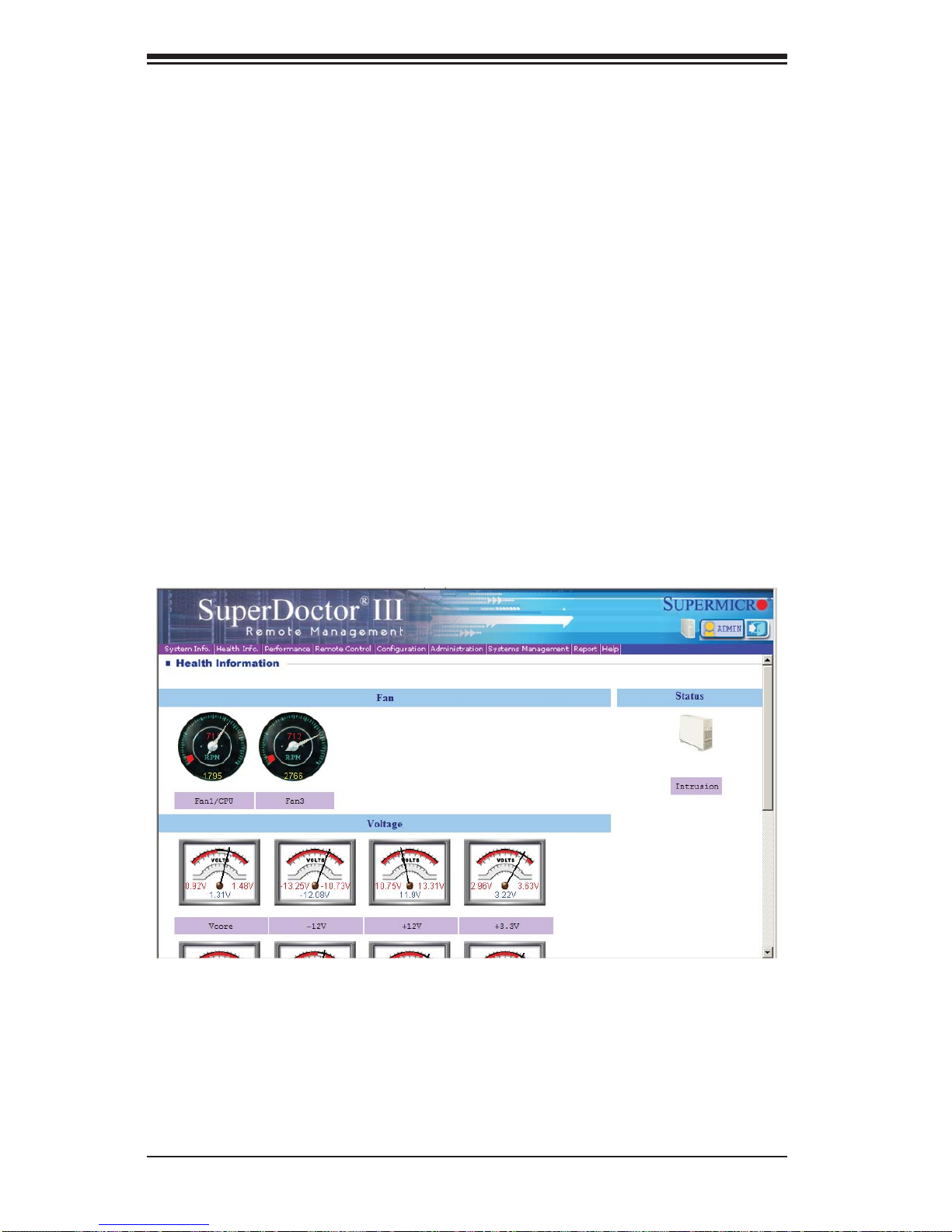
5-28
SUPERSERVER 1027R-73DAF User's Manual
Supero Doctor III Interface Display Screen (Health Information)
SuperDoctor III
The SuperDoctor® III program is a Web base management tool that supports remote
management capability. It includes Remote and Local Management tools. The local
management is called SD III Client. The SuperDoctor III program included on the
CD-ROM that came with your serverboard allows you to monitor the environment
and operations of your system. SuperDoctor III displays crucial system information
such as CPU temperature, system voltages and fan status. See the Figure below
for a display of the SuperDoctor III interface.
Note: The default User Name and Password for SuperDoctor III is ADMIN / ADMIN.
Note: When SuperDoctor is fi rst installed, it adopts the temperature threshold set-
tings that have been set in BIOS. Any subsequent changes to these thresholds
must be made within SuperDoctor, as the SuperDoctor settings override the BIOS
settings. To set the BIOS temperature threshold settings again, you would fi rst need
to uninstall SuperDoctor.
Page 77
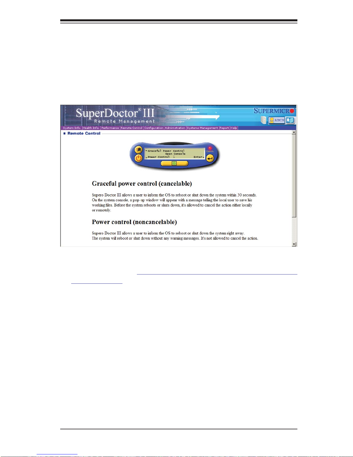
Chapter 5: Advanced Serverboard Setup
5-29
Supero Doctor III Interface Display Screen (Remote Control)
Note: The SuperDoctor III program and User's Manual can be downloaded from the
Supermicro web site at http://www.supermicro.com/products/accessories/software/
SuperDoctorIII.cfm.
For Linux, we recommend using SuperDoctor II.
Page 78

5-30
SUPERSERVER 1027R-73DAF User's Manual
5-13 Onboard Battery
Care must be taken to assure that the chassis cover is in place when the 1027R73DAF is operating to assure proper cooling. Out of warranty damage to the system
can occur if this practice is not strictly followed.
Figure 5-5. Installing the Onboard Battery
LITHIUM BATTERY
BATTERY HOLDER
Please handle used batteries carefully. Do not damage the battery in any way; a
damaged battery may release hazardous materials into the environment. Do not
discard a used battery in the garbage or a public landfi ll. Please comply with the
regulations set up by your local hazardous waste management agency to dispose
of your used battery properly.
Page 79

Chapter 6: Advanced Chassis Setup
6-1
Chapter 6
Advanced Chassis Setup
This chapter covers the steps required to install components and perform maintenance on the SC113 chassis. For component installation, follow the steps in the
order given to eliminate the most common problems encountered. If some steps
are unnecessary, skip ahead to the next step.
Tools Required: The only tool you will need to install components and perform
maintenance is a Philips screwdriver.
6-1 Static-Sensitive Devices
Electrostatic discharge (ESD) can damage electronic com ponents. To prevent
damage to any printed circuit boards (PCBs), it is important to handle them very
carefully.
The following measures are generally suffi cient to protect your equipment from
ESD damage.
Precautions
• Use a grounded wrist strap designed to prevent static discharge.
• Touch a grounded metal object before removing any board from its antistatic
bag.
• Handle a board by its edges only; do not touch its components, peripheral chips,
memory modules or gold contacts.
• When handling chips or modules, avoid touching their pins.
• Put the serverboard, add-on cards and peripherals back into their antistatic
bags when not in use.
• For grounding purposes, make sure your computer chassis provides excellent
conductivity between the power supply, the case, the mounting fasteners and
the serverboard.
Page 80

6-2
SUPERSERVER 1027R-73DAF Manual
Figure 6-1. Chassis: Front and Rear Views
6-2 Control Panel
The control panel (located on the front of the chassis) must be connected to the
JF1 connector on the serverboard to provide you with system status indications. A
ribbon cable has bundled these wires together to simplify the connection. Connect
the cable from JF1 on the serverboard to the appropriate header on the Control
Panel PCB (printed circuit board). Make sure the red wire plugs into pin 1 on both
connectors. Pull all excess cabling out of the airfl ow path.
The control panel LEDs inform you of system status. See "Chapter 3: System Interface" for details on the LEDs and the control panel buttons. Details on JF1 can
be found in "Chapter 5: Advanced Serverboard Installation."
6-3 System Cooling
Six 4-cm heavy-duty counter-rotating fans provide the cooling for the system. Each
fan unit is actually made up of two fans joined back-to-back, which rotate in opposite
directions. This counter-rotating action generates exceptional airfl ow and works to
dampen vibration levels.
System Fan Failure
Fan speed is controlled by system temperature via IPMI. If a fan fails, the remaining
fans will ramp up to full speed. Replace any failed fan at your earliest convenience
with the same type and model (the system can continue to run with a failed fan).
The 1027R-73DAF system includes six pre-installed fans.
Control PanelDVD-ROM Drive (optional)
Hot-Swap Drive Bays (8)
I/O Ports (see Figure 5-2)
Power Supply
PCI Expansion Slot (w/ Riser Card)
Page 81

Chapter 6: Advanced Chassis Setup
6-3
Replacing a System Fan (Figure 6-2)
1. Open the chassis while the system is running to determine which fan has
failed. Never run the server for an extended period of time with the chassis
open.
2. Turn off the power to the system and unplug the power cord from the power
supply.
3. Remove the failed fan's wiring from the fan header on the serverboard.
4. Lift the failed fan from the chassis and pull it completely out.
5. Place the new fan into the vacant space in the housing while making sure the
arrows on the top of the fan (indicating air direction) point in the same direction as the arrows on the other fans.
6. Reconnect the fan wires to the same chassis fan header as the previous fan.
7. Power up the system and check that the fan is working properly before replacing the chassis cover.
Page 82

6-4
SUPERSERVER 1027R-73DAF Manual
6-4 Drive Bay Installation/Removal
Accessing the Drive Bays
Hard Drives: Because of their hotswap capability, you do not need to access the
inside of the chassis or power down the system to install or replace hard drives.
Proceed to the next section for instructions.
DVD-ROM Drive: For installing/removing a DVD-ROM drive, you will need to gain
access to the inside of the system by removing the top cover of the chassis. Proceed
to the "DVD-ROM Drive Installation" section later in this chapter for instructions.
Note: Only a "slim" DVD-ROM drive will fi t into the 1027R-73DAF.
Hard Drive Installation
The hard drives are mounted in drive carriers to simplify their installation and
removal from the chassis. These carriers also help promote proper airfl ow for
the drive bays. For this reason, even empty carriers without drives installed must
remain in the chassis.
Installing a Hard Drive into a Drive Carrier (Figure 6-3)
1. Insert a drive into the carrier with the PCB side facing down and the connector end toward the rear of the carrier.
Figure 6-2: Replacing a System Fan
Page 83

Chapter 6: Advanced Chassis Setup
6-5
2. Align the drive in the carrier so that the screw holes of both line up. Note that
there are holes in the carrier marked “SATA” to aid in correct installation.
3. Secure the drive to the carrier with four screws as illustrated below.
4. Insert the drive carrier into its bay, keeping the carrier oriented so that the
hard drive is on the top of the carrier and the release button is on the right
side. When the carrier reaches the rear of the bay, the release handle will
retract.
5. Push the handle in until it clicks into its locked position
Removing a Hard Drive (Figure 6-4)
1. To remove a carrier, push the release button located beside the drive LEDs.
2. Swing the handle fully out and use it to pull the unit straight out (see Figure
6-4).
Caution: Except for short periods of time (such as for swapping hard drives), do not
operate the server with the hard drive carriers empty.
Figure 6-3: Installing a Hard Drive into a Carrier
Page 84

6-6
SUPERSERVER 1027R-73DAF Manual
Figure 6-4. Removing a Hard Drive
1
1
1
2
DVD Drive Installation
The SC113 chassis includes a pre-installed DVD-ROM.
Installing or Replacing a DVD-ROM Drive (Figure 6-5)
1. Power down the system and if necessary, remove the server from the rack
and the front bezel from the chassis.
2. Remove the chassis cover.
3. Unplug the drives power and data cables from the serverboard and/or backplane.
4. If you are adding a new drive: Remove the mini-bezel (grate) from the drive
bay The bezel can be removed by pulling out the hard drive beneath the
DVD-ROM, then pulling the mini-bezel forward.
If you are replacing a drive: Locate the locking tab at the rear (left hand side
when viewed from the front) of the DVD-ROM drive. Push the tab toward the
drive and push the drive unit out the front of the chassis.
Page 85

Chapter 6: Advanced Chassis Setup
6-7
5. Insert the new drive unit in the slot until the tab locks in place.
6. Reconnect the data and power cables.
7. Replace the chassis cover (replace the server in the rack, if necessary) and
power up the system.
Figure 6-5. Installing the DVD-ROM Drive
Drive Screw
Drive Screws
Mini Bezel Lock Screw
Page 86

6-8
SUPERSERVER 1027R-73DAF Manual
6-5 Power Supply
The SuperServer 1027R-73DAF has a single 560W power supply.
If the power supply module fails, the system will shut down and you will need to
replace the module. Replacements can be ordered directly from Supermicro (see
contact information in the Preface).
As there is only one power supply module in the system, power must be completely removed from the server before removing and replacing the power supply
for whatever reason.
Replacing the Power Supply (Figure 6-6)
1. Power down the server and unplug the AC power cord.
2. Remove the two screws located on the side of the power supply bay and set
them aside for later use.
3. Gently slide the power supply out the back of the chassis.
4. Replace the failed power module with another of the same model.
5. Slide the new power supply module into the power supply bay.
6. Align the holes on the side of the power supply with the holes in the side of
the power supply bay. Secure the power supply by replacing the previously
removed screws.
7. Plug the AC power cord into the back of the module and power-up the server.
Figure 6-6. Removing/Replacing the Power Supply
Page 87

Chapter 7: BIOS
7-1
Chapter 7
BIOS
7-1 Introduction
This chapter describes the AMI BIOS Setup utility for the X9DRD-7JLN4F/X9DRD7LN4F It also provides the instructions on how to navigate the AMI BIOS Setup
utility screens. The AMI ROM BIOS is stored in a Flash EEPROM and can be
easily updated.
Starting BIOS Setup Utility
To enter the AMI BIOS Setup utility screens, press the <Del> key while the system
is booting up.
Note: In most cases, the <Del> key is used to invoke the AMI BIOS setup
screen. There are a few cases when other keys are used, such as <F3>,
<F4>, etc.
Each main BIOS menu option is described in this manual. The Main BIOS setup
menu screen has two main frames. The left frame displays all the options that can
be confi gured. Grayed-out options cannot be confi gured. Options in blue can be
confi gured by the user. The right frame displays the key legend. Above the key
legend is an area reserved for informational text. When an option is selected in
the left frame, it is highlighted in white. Often informational text will accompany it.
Note: The AMI BIOS has default informational messages built in. The
manufacturer retains the option to include, omit, or change any of these
informational messages.
The AMI BIOS Setup utility uses a key-based navigation system called "hot keys."
Most of the AMI BIOS setup utility "hot keys" can be used at any time during setup
navigation. These keys include <F3>, <F4>, <Enter>, <ESC>, arrow keys, etc.
Note 1: Options printed in Bold are default settings.
Note 2: <F3> is used to load optimal default settings. <F4> is used to save
the settings and exit the setup utility.
Page 88

7-2
SUPERSERVER 1027R-73DAF User's Manual
How To Change the Confi guration Data
The confi guration data that determines the system parameters may be changed by
entering the AMI BIOS Setup utility. This Setup utility can be accessed by pressing
<Delete> at the appropriate time during system boot.
Note: For AMI UEFI BIOS Recovery, please refer to the UEFI BIOS Recovery User Guide posted @
http://www.supermicro.com/support/manuals/.
Starting the Setup Utility
Normally, the only visible Power-On Self-Test (POST) routine is the memory test.
As the memory is being tested, press the <Delete> key to enter the main menu of
the AMI BIOS Setup utility. From the main menu, you can access the other setup
screens. An AMI BIOS identifi cation string is displayed at the left bottom corner of
the screen below the copyright message.
Warning! Do not upgrade the BIOS unless your system has a BIOS-related issue. Flashing the wrong BIOS can cause irreparable damage to the system. In
no event shall the manufacturer be liable for direct, indirect, special, incidental,
or consequential damage arising from a BIOS update. If you have to update the
BIOS, do not shut down or reset the system while the BIOS is being updated to
avoid possible boot failure.
7-2 Main Setup
When you fi rst enter the AMI BIOS Setup utility , you will enter the Main setup screen.
You can always return to the Main setup screen by selecting the Main tab on the
top of the screen. The Main BIOS Setup screen is shown below.
Page 89

Chapter 7: BIOS
7-3
The AMI BIOS Main menu displays the following information:
System Date/System Time
Use this option to change the system time and date. Highlight System Time or
System Date using the arrow keys. Enter new values through the keyboard and
press <Enter>. Press the <Tab> key to move between fi elds. The date must be
entered in Day MM/DD/YY format. The time is entered in HH:MM:SS format. (Note:
The time is in the 24-hour format. For example, 5:30 P.M. appears as 17:30:00.).
Supermicro X9DRD-7LN4F
Version
This item displays the SMC version of the BIOS ROM used in this system.
Build Date
This item displays the date that the BIOS Setup utility was built.
Memory Information
Total Memory
This displays the amount of memory that is available in the system.
Page 90

7-4
SUPERSERVER 1027R-73DAF User's Manual
7-3 Advanced Setup Confi gurations
Select the Advanced tab to access the following submenu items.
XBoot Feature
Quiet Boot
This feature allows the user to select bootup screen display between POST messages and the OEM logo. Select Disabled to display the POST messages. Select
Enabled to display the OEM logo instead of the normal POST messages. The options are Enabled and Disabled.
AddOn ROM Display Mode
Use this item to set the display mode for the Option ROM. Select Keep Current to
use the current AddOn ROM Display setting. Select Force BIOS to use the Option
ROM display mode set by the system BIOS. The options are Keep Current and
Force BIOS.
Bootup Num-Lock
Use this fe ature to set the Powe r-on state for t he Numloc k key. T he options a re
Of f and On.
Wait For 'F1' If Error
Selec t Enabl ed to fo rce t he system t o wait unt il the ' F1' key is pressed i f an er ror
occu rs. Th e optio ns are Di sable d and Enabled.
Interrupt 19 Capture
Interrupt 19 is the software interrupt that handles the boot disk function. When this
item is set to Enabled, the ROM BIOS of the host adaptors will "capture" Interrupt 19
Page 91

Chapter 7: BIOS
7-5
at bootup and allow the drives that are attached to these host adaptors to function
as bootable disks. If this item is set to Disabled, the ROM BIOS of the host adaptors will not capture Interrupt 19, and the drives attached to these adaptors will not
function as bootable devices. The options are Enabled and Disabled.
Power Confi guration
Watch Dog Function
If enabled, the Watch Dog timer will allow the system to automatically reboot when
a non- re cove rab le er ro r oc cur s th at last s for m ore t han fi ve minutes. The options
are Enabl ed and Disabled.
Power Button Function
If this feature is set to Instant Off, the system will power off immediately as soon
as the user presses the power button. If this feature is set to 4 Seconds Override,
the system will power off when the user presses the power button for 4 seconds or
longer. The options are Instant Off and 4 Seconds Override.
Restore on AC Power Loss
Use this feature to set the power state after a power outage. Select Stay Off for the
system power to remain off after a power loss. Select Power On for the system
power to be turned on after a power loss. Select Last State to allow the system
to resume its last state before a power loss. The options are Stay Off, Power On,
and Last State.
XCPU Confi guration
This submenu displays the information of the CPU as detected by the BIOS. It also
allows the user to confi gure CPU settings.
XSocket 1 CPU Information/Socket 2 CPU Information
This submenu displays the following information regarding the CPUs installed
in Socket 1/ Socket 2.
• Type of CPU
• CPU Signature
• Microcode Patch
• CPU Stepping
• Maximum / Minimum CPU Speed
Page 92

7-6
SUPERSERVER 1027R-73DAF User's Manual
• Processor Cores
• Intel HT (Hyper-Threading) Technology
• Intel VT-x Technology
• Intel SMX Technology
• L1 Data Cache / L1 Code Cache
• L2 Cache
• L3 Cache
CPU Speed
This item displays the speed of the CPU installed in Socket 1/Socket 2.
64-bit
This item indicates if the CPU installed in Socket 1 or Socket 2 supports 64-bit
technology.
Clock Spread Spectrum
Select Enable to enable Clock Spectrum support, which will allow the BIOS to monitor and attempt to reduce the level of Electromagnetic Interference caused by the
components whenever needed. The options are Disabled and Enabled.
RTID (Record Types IDs)
This feature displays the total number of Record Type IDs for local and remote
pools. The options are Optimal and Alternate.
Hyper-threading
Select Enabled to support Intel Hyper-threading Technology to enhance CPU performance. The options are Enabled and Disabled.
Active Processor Cores
Set to Enabled to use a processor's second core and above. (Please refer to Intel's
website for more information.) The options are All, 1, 2, 4, and 6.
Limit CPUID Maximum
This feature allows the user to set the maximum CPU ID value. Enable this function
to boot the legacy operating systems that cannot support processors with extended
CPUID functions. The options are Enabled and Disabled (for the Windows OS).
Page 93

Chapter 7: BIOS
7-7
Execute-Disable Bit (Available if supported by the OS & the CPU)
Select Enabled to enable the Execute Disable Bit which will allow the processor
to designate areas in the system memory where an application code can execute
and where it cannot, thus preventing a worm or a virus from fl ooding illegal codes
to overwhelm the processor or damage the system during an attack. The default is
Enabled. (Refer to Intel and Microsoft Web sites for more information.)
Intel
®
AES-NI
Select Enable to use the Intel Advanced Encryption Standard (AES) New Instructions (NI) to ensure data security. The options are Enabled and Disabled.
MLC Streamer Prefetcher (Available when supported by the CPU)
If set to Enabled, the MLC (mid-level cache) streamer prefetcher will prefetch
streams of data and instructions from the main memory to the L2 cache to improve
CPU performance. The options are Disabled and Enabled.
MLC Spatial Prefetch (Available when supported by the CPU)
If this feature is set to Disabled, The CPU prefetches the cache line for 64 bytes.
If this feature is set to Enabled the CPU fetches both cache lines for 128 bytes as
comprised. The options are Disabled and Enabled.
DCU Streamer Prefetcher (Available when supported by the CPU)
Select Enabled to support Data Cache Unit (DCU) prefetch of L1 data to speed
up data accessing and processing in the DCU to enhance CPU performance. The
options are Disabled and Enabled.
DCU IP Prefetcher
Select Enabled for DCU (Data Cache Unit) IP Prefetcher support, which will prefetch
IP addresses to improve network connectivity and system performance. The options
are Enabled and Disabled.
Intel® Virtualization Technology (Available when supported by the CPU)
Select Enabled to support Intel Virtualization Technology, which will allow one
platfo rm to r un mult iple op erati ng system s and app licat ions i n indep endent p ar titions, creating multiple "virtual" systems in one physical computer. The options
are Enabled and Disabled.
Note: If there is any change to this setting, you will need to power off and
restar t the system for the change to take ef fect. Please refer to Intel’s
website for d etaile d infor matio n.)
Page 94

7-8
SUPERSERVER 1027R-73DAF User's Manual
X CPU Power Management Confi guration
This submenu allows the user to confi gure the following CPU Power Manage-
ment settings.
Power Technology
Select Energy Effi ciency to support power-saving mode. Select Custom to cus-
tomize system power settings. Select Disabled to disable power-saving settings.
The options are Disabled, Energy Effi cient, and Custom. If the option is set to
Custom, the following items will display:
EIST (Available when Power Technology is set to Custom)
EIST (Enhanced Intel SpeedStep Technology) allows the system to automatically adjust processor voltage and core frequency to reduce power
consumption and heat dissipation. The options are Disabled (GV3 Disabled),
and Enabled (GV3 Enabled). (Note: GV3 is Intel Speedstep support used
on older platforms. Please refer to Intel’s website for detailed information.)
Turbo Mode (Available when Power Technology is set to Custom)
Select Enabled to use the Turbo Mode to boost system performance. The
options are Enabled and Disabled.
C1E Support (Available when Power Technology is set to Custom)
Select Enabled to enable Enhanced C1 Power State to boost system performance. The options are Enabled and Disabled.
CPU C3 Report (Available when Power Technology is set to Custom)
Select Enabled to allow the BIOS to report the CPU C3 State (ACPI C2) to
the operating system. During the CPU C3 State, the CPU clock generator
is turned off. The options are Enabled and Disabled.
CPU C6 Report (Available when Power Technology is set to Custom)
Select Enabled to allow the BIOS to report the CPU C6 State (ACPI C3) to
the operating system. During the CPU C6 State, the power to all cache is
turned off. The options are Enabled and Disabled.
CPU C7 Report (Available when Power Technology is set to Custom)
Select Enabled to allow the BIOS to report the CPU C7 State (ACPI C3) to
the operating system. CPU C7 State is a processor-specifi c low C-State.
The options are Enabled and Disabled.
Page 95

Chapter 7: BIOS
7-9
Package C-State limit (Available when Power Technology is set to
Custom)
This feature allows the user to set the limit on the C-State package register.
The options are C0, C2, C6, and No Limit.
Energy/Performance Bias
Use this feature to select an appropriate fan setting to achieve maximum system
performance (with maximum cooling) or maximum energy effi ciency with maxi-
mum power saving). The fan speeds are controlled by the fi rmware management
via IPMI 2.0. The options are Performance, Balanced Performance, Balanced
Energy, and Energy Effi cient.
Factory Long Duration Power Limit
This item displays the power limit (in watts) set by the manufacturer during which
long duration power is maintained.
Long Duration Power Limit
This item displays the power limit (in watts) set by the user during which long
duration power is maintained. The default setting is 0.
Factory Long Duration Maintained
This item displays the period of time (in seconds) set by the manufacturer during
which long duration power is maintained.
Long Duration Maintained
This item displays the period of time (in seconds) during which long duration
power is maintained. The default setting is 0.
Recommended Short Duration Power
This item displays the short duration power settings (in watts) recommended by
the manufacturer.
Short Duration Power Limit
During Turbo Mode, the system may exceed the processors default power setting
and exceed the Short Duration Power limit. By increasing this value, the processor can provide better performance for short duration. This item displays the time
period during which short duration power is maintained. The default setting is 0.
Page 96

7-10
SUPERSERVER 1027R-73DAF User's Manual
XChipset Confi guration
XNorth Bridge
This feature allows the user to confi gure the settings for the Intel North Bridge.
XIntegrated IO Confi guration
Intel® VT-d
Select Enabled to enable Intel Virtualization Technology support for Direct I/O
VT-d by reporting the I/O device assignments to the VMM (Virtual Machine
Monitor) through the DMAR ACPI Tables. This feature offers fully-protected I/O
resource sharing across Intel platforms, providing greater reliability, security
and availability in networking and data-sharing. The options are Enabled and
Disabled.
Intel® I/OAT
Select Enabled to enable Intel I/OAT (I/O Acceleration Technology), which signifi cantly reduces CPU overhead by leveraging CPU architectural improvements
and freeing the system resource for other tasks. The options are Disabled and
Enabled.
DCA Support
When set to Enabled, this feature uses Intel's DCA (Direct Cache Access)
Technology to improve data transfer effi ciency. The options are Enabled and
Disabled.
IIO 1 PCIe Port Bifurcation Control
This submenu confi gures the following IO PCIe Port Bifurcation Control settings
for IIO 1 PCIe ports to determine how the available PCI-Express lanes to be
distributed between the PCI-Exp. Root Ports.
CPU1 Slot1 PCI-E 3.0 x8 Link Speed/ CPU1 Slot2 PCI-E 3.0 x8 Link
Speed/ CPU1 Slot6 PCI-E 3.0 x8 Link Speed/CPU2 Slot3 PCI-E 3.0 x8
Link Speed/CPU2 Slot4 PCI-E 3.0 x8 Link Speed/CPU2 Slot5 PCI-E 3.0 x8
Link Speed
Select GEN1 for the device installed on the slot specifi ed to support PCI-Exp
Generation 1. Select GEN2 for the device installed on the slot specifi ed to support
PCI-Exp Generation 2. Select GEN3 for the device installed on the slot specifi ed
to support PCI-Exp Generation 3. The options are GEN1, GEN2, and GEN3.
Page 97

Chapter 7: BIOS
7-11
IIO 2 PCIe Port Bifurcation Control
This submenu confi gures the following IO PCIe Port Bifurcation Control settings
for IIO 2 PCIe ports to determine how the available PCI-Express lanes to be
distributed between the PCI-Exp. Root ports.
XQPI Confi guration
Current QPI Link
This item displays the current status of the QPI Link.
Current QPI Frequency
This item displays the frequency of the QPI Link.
Isoc
Select Enabled to enable Isochronous support to meet QoS (Quality of Service)
requirements. This feature is especially important for virtualization technology.
The options are Enabled and Disabled.
QPI (Quick Path Interconnect) Link Speed Mode
Use this feature to select data transfer speed for QPI Link connections. The
options are Slow and Fast.
QPI Link Frequency Select
Use this feature to select the desired QPI frequency. The options are Auto, 6.4
GT/s, 7.2 GT/s, and 8.0 GT/s.
XDIMM Confi guration
This section displays the following DIMM information.
Current Memory Mode
This item displays the current memory mode.
Current Memory Speed
This item displays the current memory speed.
Mirroring (Available when supported by the motherboard)
Memory mirroring creates a duplicate copy of the data stored in the memory to
enhance data security.
Sparing (Available when supported by the motherboard)
Memory sparing enhances system reliability, availability, and serviceability.
Page 98

7-12
SUPERSERVER 1027R-73DAF User's Manual
XDIMM Information
CPU Socket 1 DIMM Information, CPU Socket 2 DIMM Information
The status of the memory modules detected by the BIOS will be displayed as
detected by the BIOS.
Memory Mode
When Independent is selected, all DIMMs are available to the operating system.
When Mirroring is selected, the motherboard maintains two identical copies of all
data in memory for data backup. When Lock Step is selected, the motherboard
uses two areas of memory to run the same set of operations in parallel. The
options are Independent, Mirroring, and Lock Step.
DRAM RAPL Mode
RAPL (Running Average Power Limit) provides mechanisms to enforce power
consumption limits on supported processors The options are Disabled, DRAM
RAPL MODE0, and DRAM RAPL MODE1.
DDR Speed
Use this feature to force a DDR3 memory module to run at a frequency other than
what is specifi ed in the specifi cation. The options are Force DDR3-800, Force
DDR3-1066, Force DDR3-1333, Force DDR3-1600 and Force SPD, and Auto.
Channel Interleaving
This feature selects from the different channel interleaving methods. The options
are Auto, 1 Way, 2 Way, 3, Way, and 4 Way.
Rank Interleaving
This feature allows the user to select a rank memory interleaving method. The
options are Auto, 1 Way, 2 Way, 4, Way, and 8 Way.
Patrol Scrub
Patrol Scrubbing is a process that allows the CPU to correct correctable memory
errors detected on a memory module and send the correction to the requestor
(the original source). When this item is set to Enabled, the IO hub will read and
write back one cache line every 16K cycles, if there is no delay caused by internal
processing. By using this method, roughly 64 GB of memory behind the IO hub
will be scrubbed every day. The options are Enabled and Disabled.
Demand Scrub
Demand Scrubbing is a process that allows the CPU to correct correctable
memory errors found on a memory module. When the CPU or I/O issues a
demand-read command, and the read data from memory turns out to be a
Page 99

Chapter 7: BIOS
7-13
correctable error, the error is corrected and sent to the requestor (the original
source). Memory is updated as well. Select Enabled to use Demand Scrubbing
for ECC memory correction. The options are Enabled and Disabled.
Data Scrambling
Select Enabled to enable data scrambling to ensure data security and integrity.
The options are Disabled and Enabled.
Device Tagging
Select Enabled to support device tagging. The options are Disabled and Enabled.
Thermal Throttling
Throttling improves reliability and reduces power consumption in the processor via automatic voltage control during processor idle states. The options are
Disabled and CLTT (Closed Loop Thermal Throttling).
XSouth Bridge Confi guration
This feature allows the user to confi gure the settings for the Intel PCH chip.
PCH Information
This feature displays the following PCH information.
Name: This item displays the name of the PCH chip.
Stepping: This item displays the status of the PCH stepping.
USB Devices: This item displays the USB devices detected by the BIOS.
All USB Devices
This feature enables all USB ports/devices. The options are Disabled and Enabled.
(If set to Enabled, EHCI Controller 1 and Controller 2 will appear.)
EHCI Controller 1/EHCI Controller 2 (Available when All USB Devices is set
to Enabled)
Select Enabled to enable EHCI (Enhanced Host Controller Interface) Controller 1
or Controller 2. The options are Disabled and Enabled.
Legacy USB Support (Available when USB Functions is not Disabled)
Select Enabled to support legacy USB devices. Select Auto to disable legacy support if USB devices are not present. Select Disabled to have USB devices available
for EFI (Extensive Firmware Interface) applications only. The settings are Enabled
Disabled, and Auto.
Page 100

7-14
SUPERSERVER 1027R-73DAF User's Manual
Port 60/64 Emulation
Select Enabled to enable I/O port 60h/64h emulation support for the legacy USB
keyboard so that it can be fully supported by the operating systems that does not
recognize a USB device. The options are Disabled and Enabled.
EHCI Hand-Off
This item is for operating systems that do not support Enhanced Host Controller
Interface (EHCI) hand-off. When enabled, EHCI ownership change will be claimed
by the EHCI driver. The options are Disabled and Enabled.
XSATA Confi guration
When this submenu is selected, the AMI BIOS automatically detects the presence
of IDE or SATA devices and displays the following items.
SATA Port0~SATA Port5: The AMI BIOS displays the status of each SATA port
as detected by the BIOS.
SATA Mode
Use this feature to confi gure SATA mode for a selected SATA port. The options are
Disabled, IDE Mode, AHCI Mode and RAID Mode. The following are displayed
depending on your selection:
IDE Mode
The following items are displayed when IDE Mode is selected:
Serial-ATA (SATA) Controller 0~1
Use this feature to activate or deactivate the SATA controller, and set the
compatibility mode. The options for SATA Controller 0 are Disabled, Enhanced, and Compatible. The options for SATA Controller 1 are Disabled
and Enhanced.
AHCI Mode
The following items are displayed when the AHCI Mode is selected.
Aggressive Link Power Management
When Enabled, the SATA AHCI controller manages the power usage of
the SATA link. The controller will put the link in a low power mode during
extended periods of I/O inactivity, and will return the link to an active state
when I/O activity resumes. The options are Enabled and Disabled.
 Loading...