

Page 1
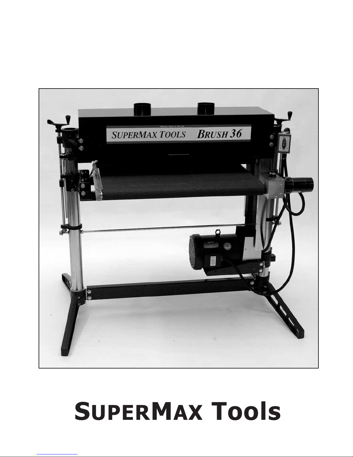
Keep This Manual Handy For Quick Reference
SUPERBRUSH OWNER’S MANUAL
For SUPERBRUSH 24 and SUPERBRUSH 36
IMPORTANT: BEFORE OPERATING YOUR SUPERBRUSH READ THE INSTRUCTIONS
IN THIS MANUAL FOR UNPACKING AND SETTING UP YOUR MACHINE.
USA
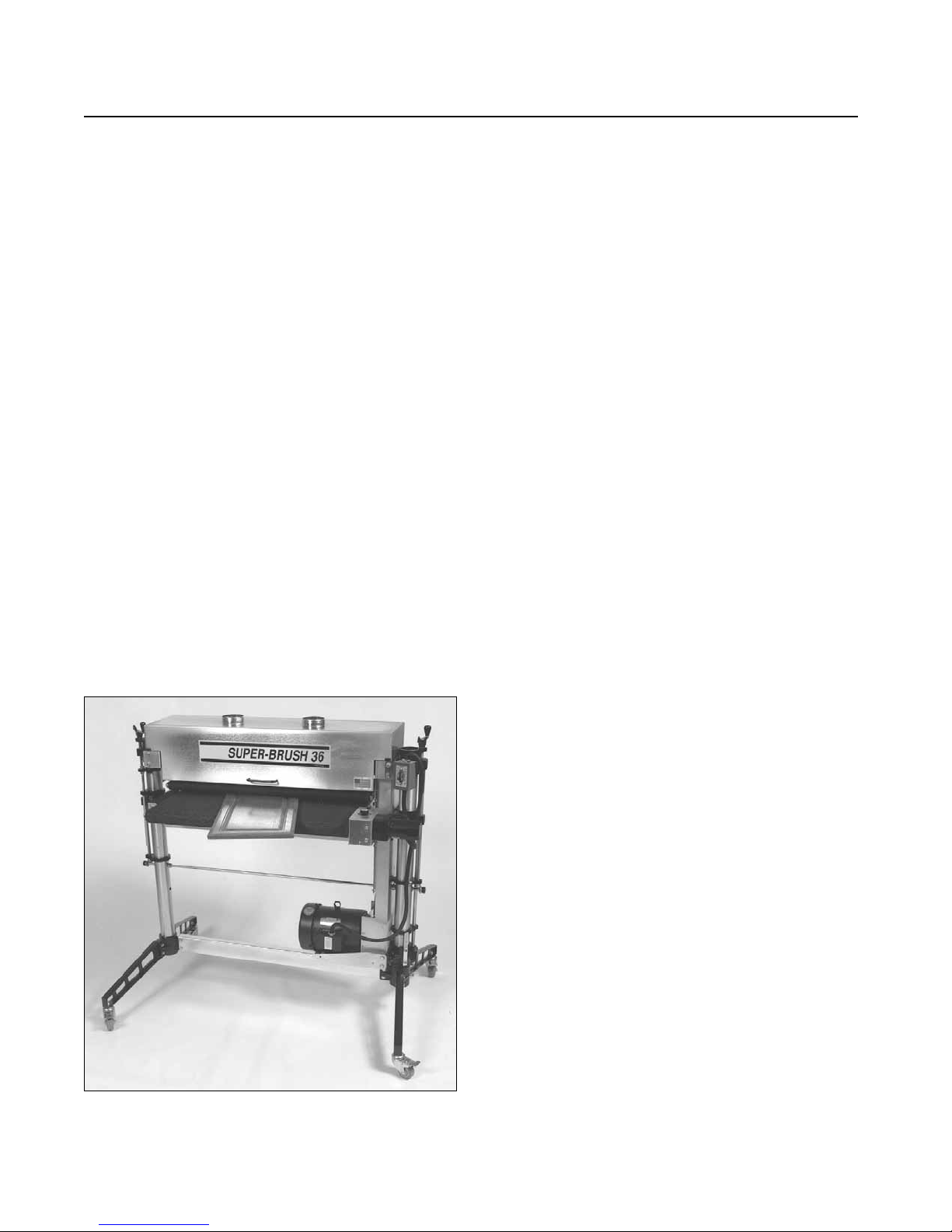
shown with optional accessories
Page 2

CAUTION, SAFETY FIRST
When maintaining and operating this machine,
always put safety first. For your own safety, read
and understand this owner’s manual before operating this machine. Always heed and follow all normal safety precautions, including the following:
• Always wear eye protection while operating
the sander.
• Always feed stock against the brush rotation.
• Never place hands or fingers under the brush
or dust cover.
• Keep hands and clothing away from operating
brush.
• Never operate the sander without its dust
cover or pulley guarding in place.
• Always maintain control of boards to avoid
kickback; know how to prevent it.
• Always disconnect electrical power before
doing any servicing or adjusting of the
machine.
MODEL IDENTIFICATION
Your SUPERBRUSH sander is one of a family of
machines from SuperMax Tools designed to help
you achieve results comparable to industrial-size
sanders at a fraction of the cost. The S
UPERBRUSH
is available in 24˝ or 36˝ sizes. For future reference,
find the model and serial numbers on the table
mount bracket (#42, page 29) and write them in
below.
Model:_________________________________
Serial Number: __________________________
Date Purchased: _________________________
Dealer: ________________________________
______________________________________
2 SUPERBRUSH OWNER’S MANUAL
CONGRATULATIONS
You have made a wise purchasing decision by
adding this “Made In USA” machine to your tool
line-up. The main purpose in inventing and developing the machine you’ve purchased was to bring a
new dimension of productivity to your workshop,
be it large or small. Right from the start, our goal
at SuperMax Tools has been to manufacture
equipment that is capable of providing you with
maximum economy, maximum utility, and maximum
performance.
Your S
UPERBRUSH will pay you back many fold
in the years ahead by helping you get better results
in less time, start to finish. This tool incorporates a
bundle of exclusive features which you will appreciate
more every time you use it. All SuperMax Tools
brush sanders feature a variable brush speed
(RPM) and the exclusive variable-speed power feed
conveyor system. Together, they provide you with
ultra-precise control, for a variety of applications.
SuperMax Tools and its dealers are committed
to providing you with innovative solutions,from
selecting the right machine to helping you get top
performance when you put it to work in your
shop. Regardless of how you take advantage of
these innovations, we are confident our equipment
will help bring you a giant step forward in precision
shop productivity.
Please read this manual first. It was designed to
help you get the most from your S
UPERBRUSH
sander. Before unpacking or using the machine,
familiarize yourself with its components, features,
and basic adjustments by reviewing the following
pages. You will find it an invaluable aid in setting
up, operating and servicing your machine. If, after
reviewing this manual, you still have a problem you
can’t solve, please call your SuperMax Tools dealer.
IMPORTANT: KEEP THIS MANUAL HANDY
Page 3

MANUAL CONTENTS 3
ABOUT THE SUPERBRUSH SYSTEM
SUPERBRUSH Nomenclature......................4
Unpacking Your S
UPERBRUSH Sander.......5
SETTING UP YOUR SUPERBRUSH
Making Electrical Connections.................6
Connecting Dust Collectors.....................7
Checking For Machine Level....................7
Checking Brush Alignment ......................7
Checking Table Height Controls..............7
Brush Speed Adjustment...........................8
Checking Conveyor Belt...........................8
OPERATING YOUR SUPERBRUSH
Basic Operating Procedures ......................9
Adjusting Tension Rollers.........................9
S
UPERBRUSH Operating Controls..............9
Setting Depth of Cut..............................10
Selecting Stock Feed Rates......................10
Using The Depth Gauge.........................11
Monthly Maintenance............................11
TIPS FOR MAXIMUM
PERFORMANCE.....................................12
TROUBLESHOOTING YOUR
SUPERBRUSH
Troubleshooting Guide: Motors..............13
Troubleshooting Guide: Conveyor..........14
Troubleshooting Guide: Machine...........15
SERVICING YOUR SUPERBRUSH
Adjusting Height Controls......................16
Adjusting Table Support Castings...........16
Adjusting Brush Head............................16
Leveling Table.........................................18
Miter Gear Alignment............................18
Brush Speed Adjustment.........................19
Replacing Brush............................20 & 23
Replacing Conveyor Belts.......................20
Replacing V-Belt ....................................21
Rotating/Replacing Bearings...................22
Replacing Electrical Components...........24
Electrical Diagrams........................25 & 26
SUPERBRUSH TECHNICAL DATA
SUPERBRUSH Specifications.....................27
Parts List For Stand.................................28
Parts List For Brush Assembly.................30
Parts List For Conveyor Assembly...........32
S
UPERBRUSH Accessories & Supplies.......35
CONTENTS
FOR YOUR SAFETY: Read all instructions carefully,
and note the safety cautions on the opposite page and on
the back cover of this manual.
Page 4
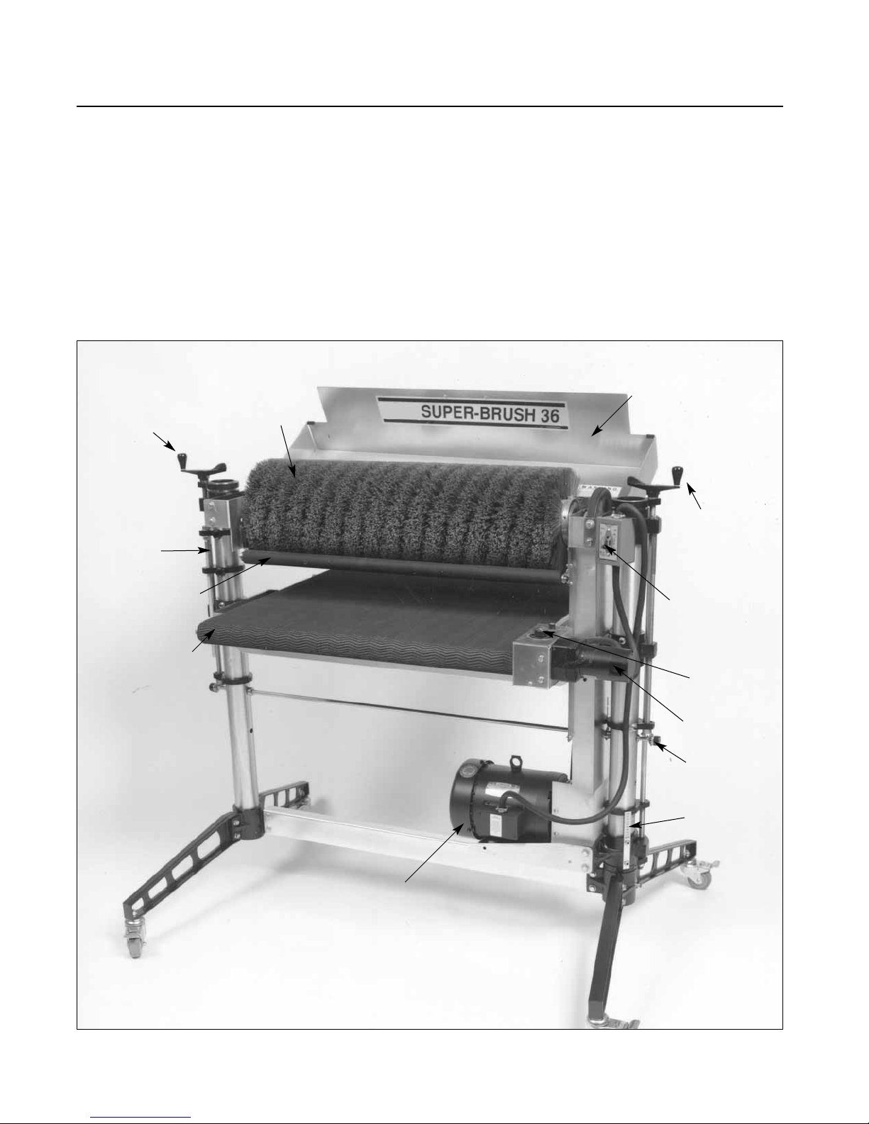
4 SUPERBRUSH OWNER’S MANUAL
This manual is designed to help familiarize you
with your S
UPERBRUSH sander, and to help you
take advantage of its exclusive features. By understanding its major components, and how they
work together, you will be able to get the most
from your investment.The S
UPERBRUSH system is
basically made up of: 1) a height adjustment handle
which raises and lowers the conveyor table; 2) a
brush speed control handle which controls brush
speed from 400 to 1200 RPM; 3) a motor starter
switch which starts and stops the drive motor and
sanding brush; and 4) a feed rate control knob
which starts feed conveyor and selects feed rate
from 0-15 feet per minute.
ABOUT THE SUPERBRUSH SYSTEM
Fig. 1. SUPERBRUSH nomenclature.
DUST COVER
BRUSH SPEED
CONTROL
HANDLE (RPM)
MOTOR
CONTROL
SWITCH
FEED RATE
CONTROL
KNOB
GEAR
MOTOR
MITER GEARS
RPM GAUGE
RIGHT (INBOARD) SIDE
MAIN MOTOR
LEFT (OUTBOARD) SIDE
DEPTH
GAUGE
FEED CONVEYOR
TENSION ROLLER
HEIGHT ADJUSTMENT
HANDLE
SANDING
BRUSH
Page 5
ABOUT THE SUPERBRUSH SYSTEM 5
UNPACKING YOUR SUPERBRUSH
Your SUPERBRUSH sander has been shipped completely
assembled from the factory in a shroud on a pallet
and shrink-wrapped in plastic. If any damage has
occurred as a result of shipment, notify the transportation company as soon as possible and ask
them to make an immediate inspection. Ask for a
damage or loss report. Also notify your dealer of
any loss or damage during shipment. See enclosed
Warranty Statement.
Important: To avoid problems and potential
damage to the machine, please read through the
unpacking instructions below before proceeding to
set up the machine in your shop.
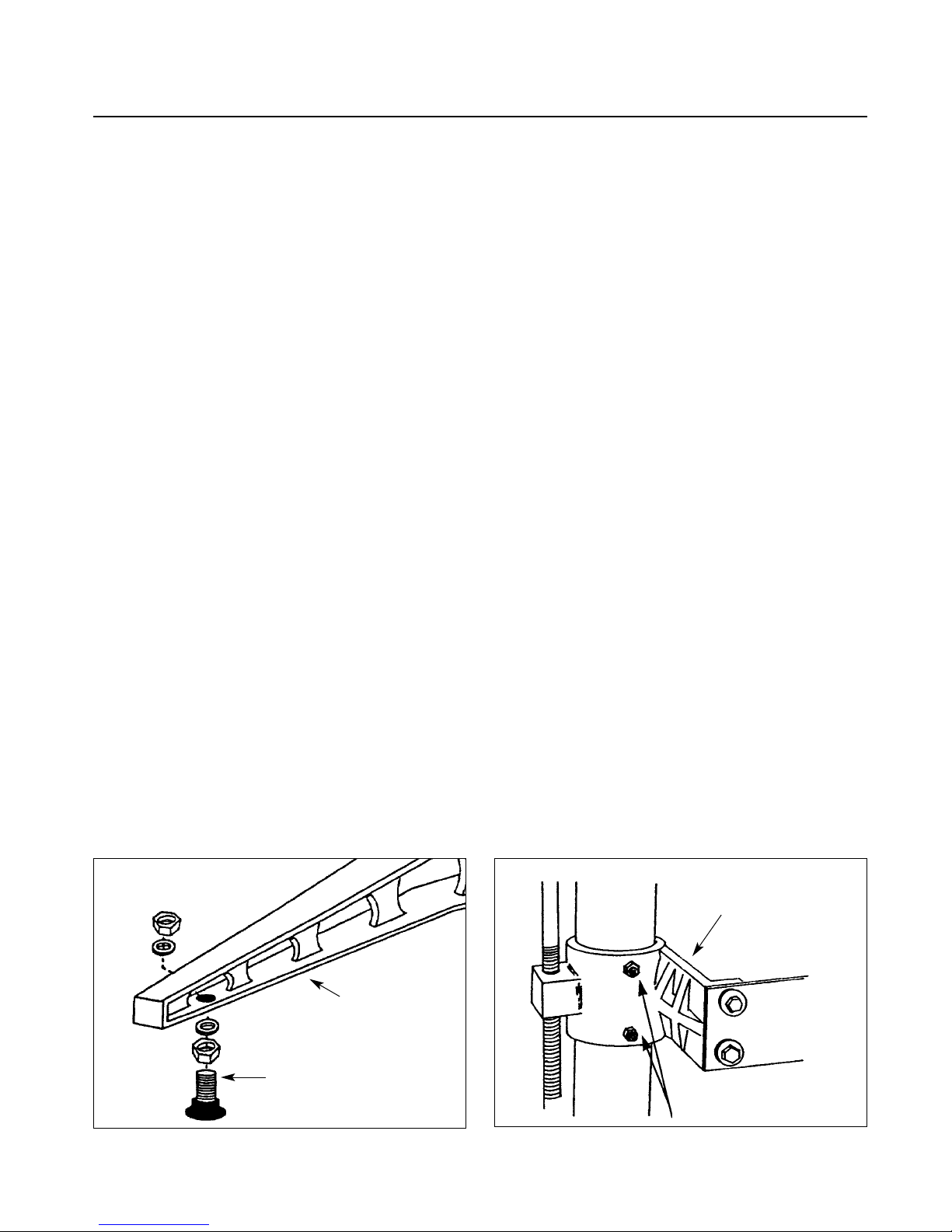
1. Unbolt the machine legs from the shipping
pallet. Install the rubber-based leveling feet or
optional caster set on legs (Fig. 2). The feet and
mounting hardware are in the STOP bag packed
with your machine.
2. Loosen the hex nuts and set screws on the
table support castings (Fig. 3) and on the motor
support casting (7)(Fig. 5). The set screws on the
table support castings have been tightened at the
factory to eliminate free-play between the castings
and the column tube during shipment. There are
two table support castings on the S
UPERBRUSH,
one each for the right and left column tubes, and
one motor support casting, all with set screws.
Important: These set screws are tightened for
shipping and must be loosened and readjusted
before operating either the height adjustment
mechanism or the brush speed control handle.
To properly adjust for operation, loosen each set
screw by first loosening its hex nut with a wrench
and then the set screw with an Allen wrench. Then
retighten each set screw with your fingers so it only
lightly touches the column tube. Hold each set
screw in position with an Allen wrench and
retighten the hex nut. Failure to follow these
procedures may result in misalignment of the
brush and/or the conveyor table.
Caution: Do not loosen the set screws on the
upper brush support castings.
Note: Some machines have a block of wood
under the main motor. If so, remove at this time.
3. Install the conveyor gear motor. Rotate the
drive roller on the conveyor system so the flat part
of the shaft is down. If necessary, connect the
conveyor motor into an appropriate AC outlet (see
page 6, “Making Electrical Connections”), to
rotate the motor output shaft coupling so the set
screws face downward. Disconnect electrical supply.
Slide the conveyor motor assembly onto the drive
roller shaft, aligning the shaft coupling and four
mounting holes. Start the four 5/16” hex head
bolts on the conveyor motor mounting bracket,
but do not tighten yet.
Next, tighten the set screws in the coupling on
the drive roller shaft, making sure they are on the
flat of the shaft. Rock the drive roller while tightening the set screws to make sure they are centered
properly on the flat. Install the bottom cover on
the control box with two screws. Then connect
power to machine and turn conveyor on full speed.
While it is running, tighten the four 5/16" bolts to
secure the conveyor motor assembly in place.
Fig. 2. Leveling foot and mounting hardware. Fig. 3. Table support casting and set screws.
LEVELING FOOT
STAND LEG
TABLE SUPPORT
CASTING
HEX NUT & SET SCREW
Page 6
6 SUPERBRUSH OWNER’S MANUAL
Your SUPERBRUSH sander was adjusted and aligned
at the factory, and it has been carefully packed for
shipment. However, because of possible stress during
transit, the unit should be thoroughly checked
before being put to use. This section covers the
pre-operational checks you should make after
unpacking and final assembly. Unnecessary problems
can be avoided if these essential checks are performed
before operating. Likewise, performing the recommended monthly maintenance procedures (page
11) will help assure trouble-free service.
MAKING ELECTRICAL CONNECTIONS
Po w er for the brush of your SUPERBRUSH is supplied
by either a 5HP, single-phase, a 5HP, three phase,
208-230V motor; or a 5HP, three phase, 460V
motor.
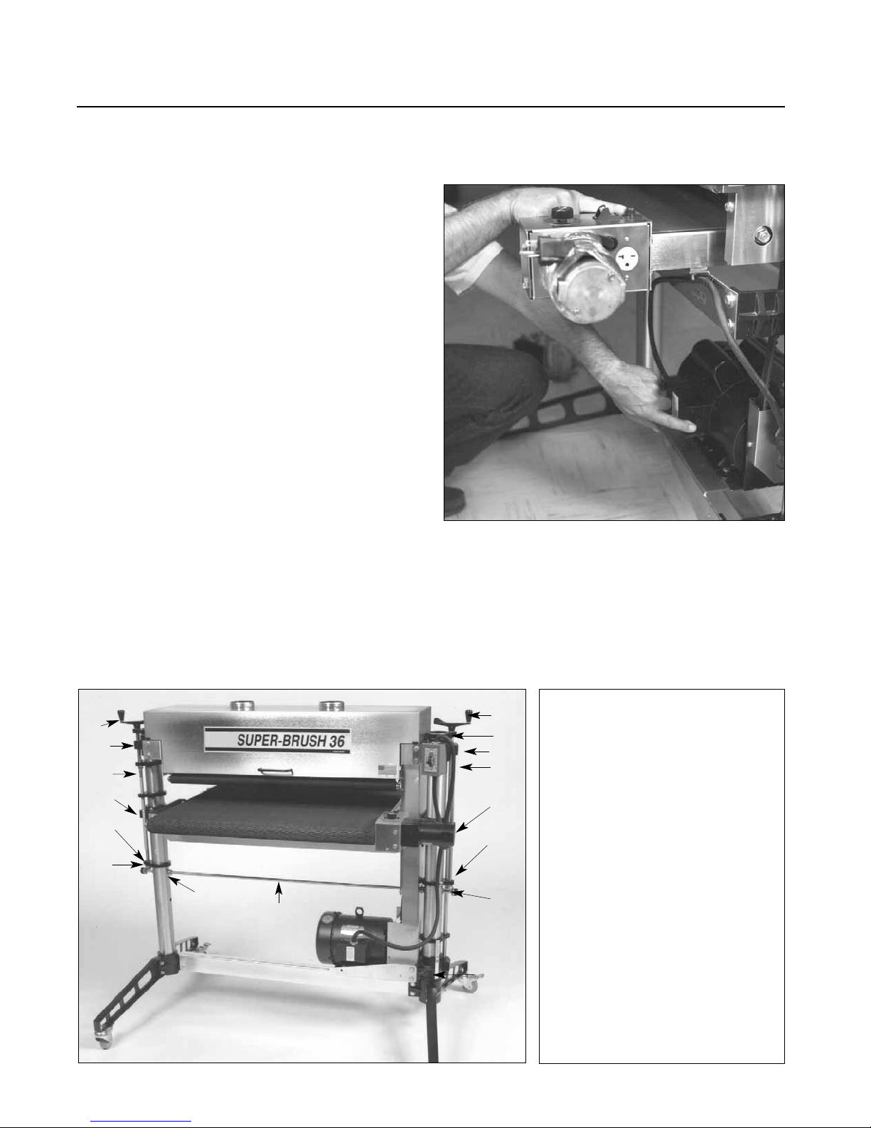
- Single phase motor: Protected by a thermal
overload switch. On single phase machines, a
NEMA 14-30 plug is provided. A 30 amp breaker
is required.
- Three phase motor: No plug is provided. It can
be hard wired to a main power source or a plug
can be installed to be used with a receptacle.
- Three phase, 208V motors require a 20 amp
breaker.
SETTING UP YOUR SUPERBRUSH
Fig. 4. Thermal-overload switch on single phase
motor (bottom) and conveyor belt motor fuse (top).
Fig. 5. SUPERBRUSH Components.
1. Brush Speed Handle.
2. Adjusting Screw Support.
3. Brush Support Casting.
4. Height Adjusting Screw.
5. Table Support Casting.
6. Miter Gear.
7. Motor Support Casting.
8. Transfer Rod.
9. Shaft Collars.
10. Height Adjustment Handle.
1
2
3
4
5
2
10
3
4
5
2
6
9
6
7
8
- Three Phase, 460V motors require a 15 amp
breaker and 5 wire connections.
Page 7
SETTING UP YOUR SUPERBRUSH 7
CONNECTING DUST COLLECTORS
Dust collection is necessary for all SUPERBRUSH
models. The SUPERBRUSH 24 is equipped with one
4˝ diameter dust exhaust port at the top of the
brush cover. The S
UPERBRUSH 36 has two 4˝ dust
exhaust ports.
To attach the S
UPERBRUSH to your collection
system, install 4˝ hose from your collector. (See
Tips For Maximum Performance, page 12 of this
manual.) The minimum recommended dust collector
capacities at the dust port(s) are: S
UPERBRUSH 24:
600
CFM; SUPERBRUSH 36: 1,200 CFM. For best
results, follow the recommendations of the manufacturer of your dust collection equipment. NOTE:
Some applications will require more dust collection
than the recommended minimum CFM.
CHECKING MACHINE FOR LEVEL
Proper leveling of the machine is essential to
achieve continued maximum performance from
the S
UPERBRUSH. Before making fine adjustments,
place the unit where it will be used in the shop.
Then adjust the four leveling feet using a carpenter’s
level both across the machine and in line with the
machine, placing the level on the conveyor bed. If
you have equipped your S
UPERBRUSH with the
optional caster set, do the same after positioning
the machine where it will be operated most often.
Mark the position of the legs on the floor with
tape so it can be returned to the same position.
HEIGHT ADJUSTMENT
The table height is controlled by the height adjustment handle (10)(Fig.5). Turning the handle raises
or lowers both sides of the table simultaneously by
transferring the handle rotation through the miter
gear and transfer rod assembly. One revolution of
the handle raises or lowers the table 3/32 of an
inch.
Before operating height adjustment, be sure both
set screws located in both table support castings
(Fig. 3) are loose to allow table support to slide on
both column tubes. (These set screws are tightened
for shipping.)
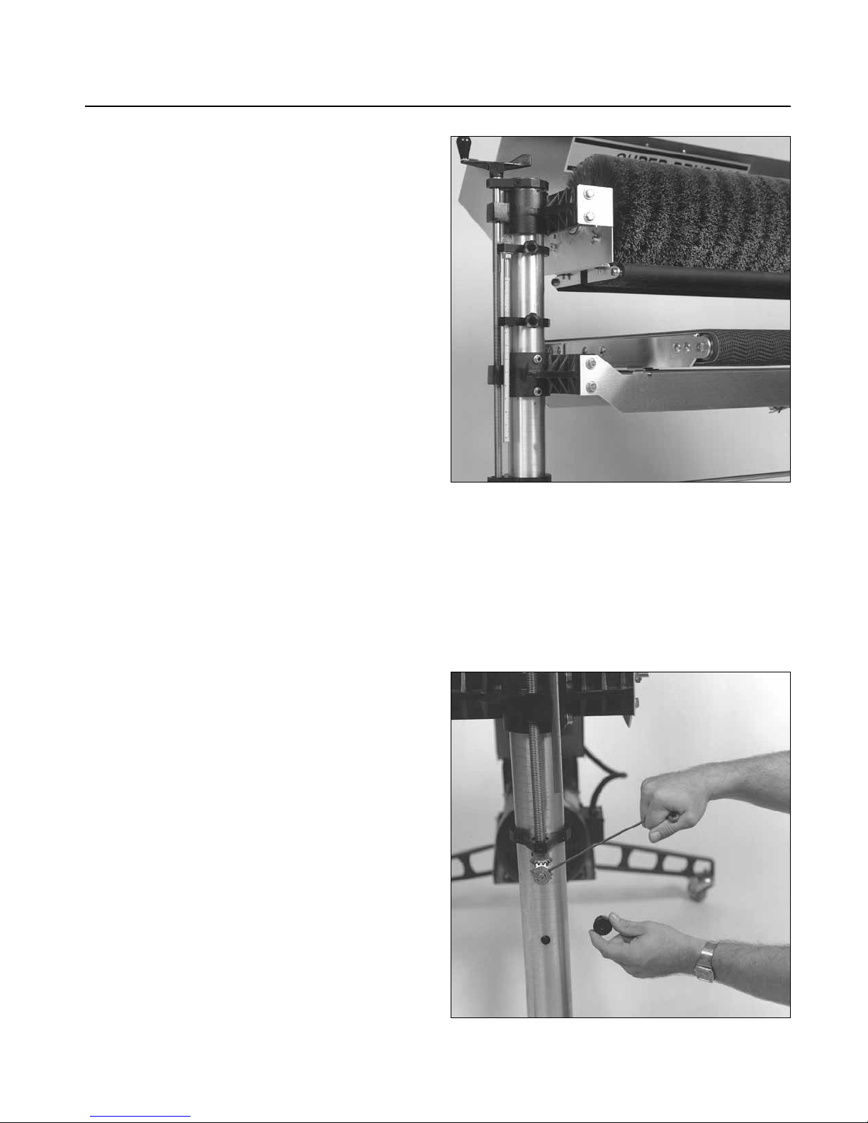
BRUSH ALIGNMENT
The brush must be parallel to the conveyor bed
surface. Brush alignment can be visually checked by
raising the tension rollers (Fig. 6) to their highest
position (See Tension Roller Adjustment page 9)
and raising the table so that the brush just contacts
the conveyor surface. Brush contact should be
Fig. 6. Checking brush alignment and table height
adjustment (outboard side).
Fig. 7. Adjusting brush alignment.
Page 8
8 SUPERBRUSH OWNER’S MANUAL
equal across the width of the conveyor. If the
S
UPERBRUSH is properly leveled (See checking
machine for level), brush misalignment can be
corrected by loosening the two set screws at the
front of the outboard brush support casting (Fig.
5) and by raising or lowering casting to correct
alignment.
NOTE: Improper brush alignment will cause
uneven results and lead to reduced brush life.
BRUSH SPEED ADJUSTMENT
The SUPERBRUSH is equipped with a variable
speed drive which allows the brush to be operated
anywhere between 400 and 1200 RPM. The faster
the brush speed, the more aggressive the brush
action. The brush speed control handle (1)(Fig. 5)
raises or lowers the motor support casting (7)(Fig.
5) which activates the variable speed drive pulley.
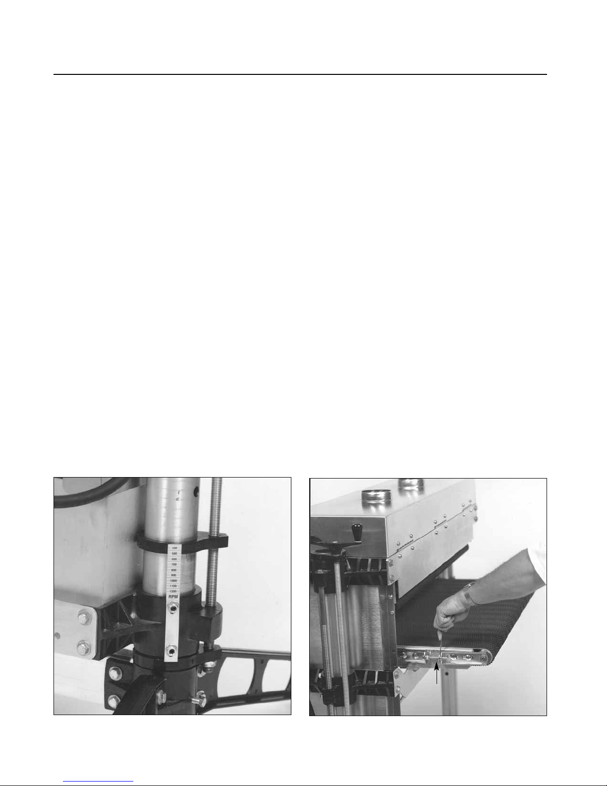
RPM GAUGE
The RPM gauge (Fig. 8) displays the brush speed
and is read where the scale intersects the top of the
screw support casting. To calibrate the gauge,
lower the motor to the lowest position. Loosen
both hex nuts while holding set screws. Position
the RPM scale so that “400” RPM intersects the
top of the screw support casting (Fig. 8). Tighten
hex nuts to hold gauge in this position.
CHECKING THE CONVEYOR BELT
Conveyor belt tracking adjustments may occasionally
be necessary during break-in and normal operation to
compensate for belt stretching. If adjustments are
necessary, follow the instructions below:
Belt tracking adjustments are made while the
conveyor belt is running. With the conveyor unit
on and set at the fastest speed setting, watch for a
tendency of the conveyor belt to drift to one side
of the conveyor. To adjust the belt tracking, tighten
the take-up screw nut (see Fig. 9) on the side the
belt is drifting toward, and loosen the take-up
screw nut on the opposite side. Adjusting the take-up
screw nuts on either side of the conveyor allows
belt tracking adjustments to be made without
affecting belt tension. Adjust the take-up screw nuts
only 1/4 turn at a time. Then allow time for the belt
to react to the adjustments before proceeding further.
Try to avoid over-adjustments.
NOTE: Make sure wrench is below surface when
brushing.
Fig. 8. Brush RPM gauge.
Fig. 9. Adjusting conveyor belt tracking.
TAKE UP
SCREW NUT
Page 9
OPERATING YOUR SUPERBRUSH 9
Before using your SUPERBR USH, r eview the previous
pages in this manual on initial set-up and adjustment.
In this section, you will learn how to operate the
machine. Note that connecting the machine to an
adequate dust collection system is necessary before
operating the unit.
The S
UPERBRUSH offers considerable control
and versatility through infinitely variable brush
speed and feed rate. Experiment with both to find the
proper sander performance for a given application.
Varying the brush speed makes the brush more or
less aggressive. Too aggressive on the brush may
tend to raise the grain or round edges. Sometimes
it may be better to make two or more passes with a
less aggressive brush or setting.
The brush is rotating against the direction of
feed; therefore, the leading edges of contours will
receive more sanding than trailing edges. Stock
should be reversed on subsequent passes to sand all
surfaces. Stock may also be fed at an angle to allow
more brush penetration on the sides.
BASIC OPERATING PROCEDURES
After you have connected the machine to a dust
collection system, you are ready to begin to use the
SUPERBRUSH. The basic operating procedure for
the S
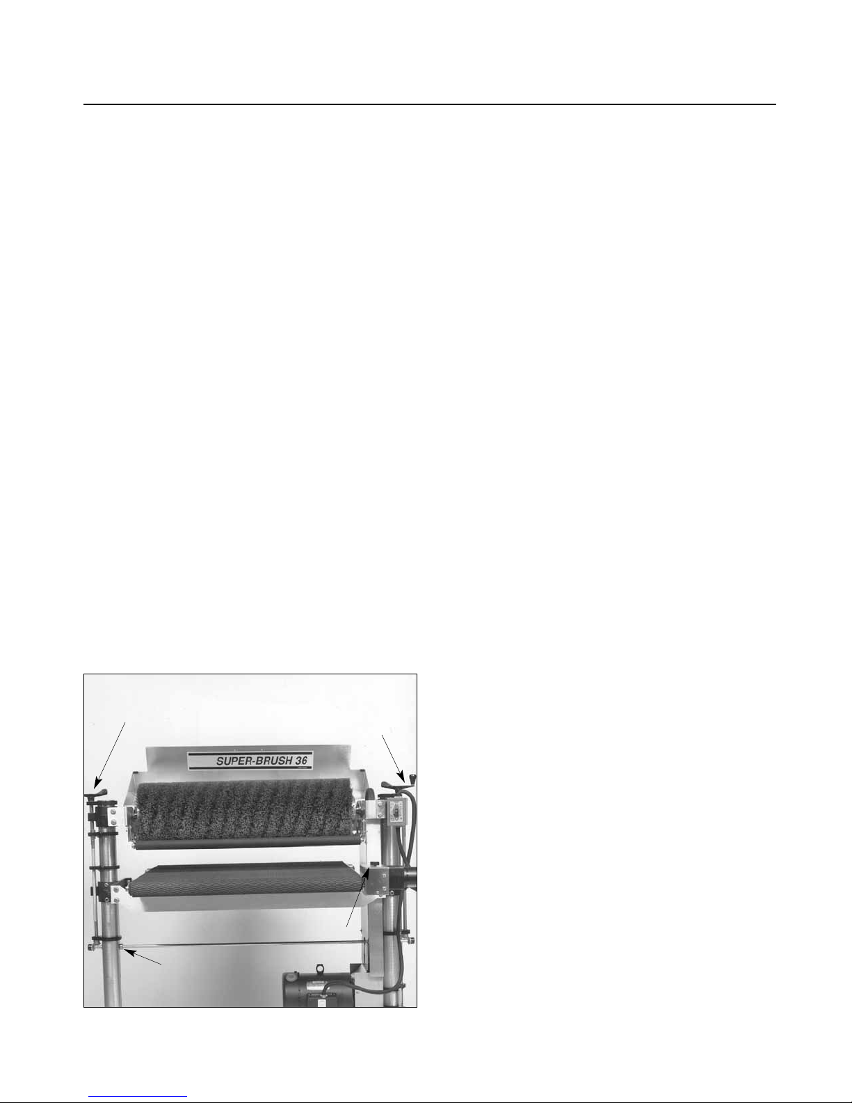
UPERBRUSH models is as follows (Fig. 10):
1. Set depth of cut/bristle contact (page 10).
2. Set tension rollers to type of stock being sanded
(See Tension Roller Adjustment below and Fig.
11)
3. Start sanding brush and select slow brush speed
(page 8).
4. Start conveyor and select feed rate (page 10)
5. Start dust collector system.
6. Feed stock through unit.
7. Gradually increase brush speed until the desired
finish is achieved (Fig. 8).
To feed stock through the S
UPERBRUSH, rest
and hold the stock to be sanded on the conveyor
table,
allowing the conveyor belt to carry the stock
into the brush. Once the stock is halfway through,
reposition yourself to the outfeed side of the
machine to receive and control the stock as it exits
the unit.
TENSION ROLLER ADJUSTMENT
Spring loaded infeed and outfeed Tension Rollers
(Fig. 11) are provided to maintain downward
pressure on stock being sanded and to prevent
slippage of the stock on the feed conveyor. When
properly set, the Tension Rollers should engage or
raise up about 1/8˝to accommodate the stock
being brushed.
The Tension Rollers can and must be adjusted
to accommodate flat surfaced stock vs highly
contoured surface stock. If the Depth Gauge is
properly calibrated (page 11), Tension Roller
height is adjusted as follows: Note: Make sur e brush
head is appropriate for application and contact.
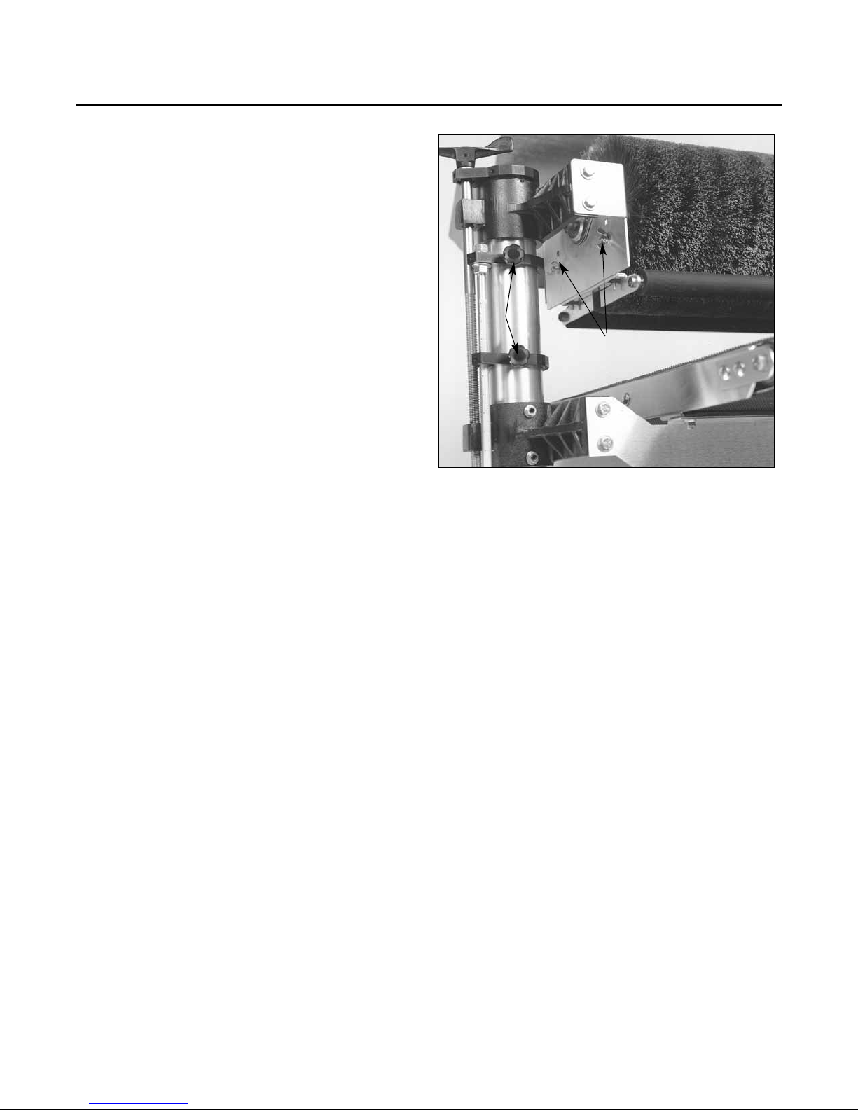
Flat Surfaced Stock: Set the bottom of the
tension rollers even with the bottom of the brush.
Loosen the four Tension Roller locking knobs (Fig.
11). Raise the table to the “0” mark on the Depth
Gauge. At this position, the brush and Tension
Rollers are resting on the table surface. Lock all
four Tension Roller knobs. For example, to brush a
3/4˝thick flat board, lower the table to 5/8˝on the
Depth Gauge. This allows 1/8˝for Tension Roller
engagement and 1/8˝brush penetration.
OPERATING YOUR SUPERBRUSH
Fig. 10. Operating controls.
SHAFT
COLLAR
HEIGHT
ADJUSTMENT
BRUSH
SPEED
CONTROL
CONVEYOR
CONTROL
Page 10
10 SUPERBRUSH OWNER’S MANUAL
Contoured Surface Stock: (Example: A 3/4
˝
thick piece of molding with 3/8˝of molding
relief.) Loosen all four tension roller locking bolts
(Fig. 11). Adjust the conveyor table 1/4˝into the
bristle tips (measure with a ruler from “0” mark on
depth gauge.). At this position, the tension rollers
are resting on the table surface and are positioned
1/4˝above the bottom of the brush. Lock all four
Tension Roller locking bolts. To brush the piece,
lower the table to the 3/8˝position on the Depth
Gauge. This allows for 1/8˝of tension roller
engagement and 3/8˝of brush penetration.
SELECTING STOCK FEED RATES
Selecting the proper feed rate is essential to proper
brushing. Feed rate controls the duration of brushing
on a particular spot. A slower feed rate allows
more brushing to occur. In some instances, a slow
feed rate and slow brush speed may produce the
same result as a fast feed rate and fast brush speed.
The variable feed rate control of the conveyor belt
adjusts the load on the machine; it can be infinitely adjusted for maximum operating performance.
A faster feed rate allows faster brushing but fewer
revolutions of the brush per inch of sanding. A
slower feed rate provides more revolutions of the
brush per inch of sanding (Fig. 10).
The best feed rate will depend on a number of
factors, including type of stock, brush, depth of
cut used, and whether the stock is fed directly in
line with the conveyor bed or at an angle.
When using a wire brush for “distressing” wood,
a brush speed of 400-600 RPM with light contact
of bristles and a moderate feed rate generally leaves
the best finish.
SETTING BRUSH DEPTH OF CUT/CONTACT
SuperMax Tools tests sample applications for all
customers before selling a S
UPERBRUSH. We rec-
ommend following the suggest RPM, contact and
conveyor settings outlined in the sample letter. If
you have questions about your application(s) or
your needs change, please contact SuperMax Tools
for updated information or new sample testing, as
brush types, materials, etc. may have changed.
The information and suggestions listed below are
not specific to any application and may have
changed since printing. Please call SuperMax
Tools if you have questions.
When a nylon or wire brush is worn and needs
changing, the bristles will either have fractured
and the brush head looks “bald” or the bristle
length has worn and the bristles are too short for
effective brushing.
When an abrasive or cloth brush is worn, the
brushing material will become smooth or the
brush will be considerably smaller in diameter as
compared to new. Cloth brush heads may only
need cleaning to rejuvenate the cloth. Please call
SuperMax Tools if you have any questions. Brush
life can vary considerably, due to RPM, contact,
type of brush, and material being brushed.
Fig. 11. Tension roller and depth gauge adjustment.
DEPTH
GAUGE
LOCKING
KNOBS
TENSION ROLLER
LOCKING BOLTS
Page 11

OPERATING YOUR SUPERBRUSH 11
Many types of brush heads may be rewound with
new bristles or re-equipped with new brush material.
Please contact SuperMax Tools if you have questions
about a new or re-wrapped brush head.
Some types of brush heads, some fladder brushes,
for example, will allow changing of the brush
material by the operator, thus eliminating the need
to send the brush head out for re-wrapping. Please
call SuperMax Tools if you have any questions
about re-wrapping a brush.
When using a wire brush for “distressing” wood,
slowing brush RPM, using light contact and a
moderate feed rate generally will give the best finish
and longest brush life.
When using a wire brush on metal, it is important
to use a light contact of the bristle tips.
Wire brushes frequently flipped end for end, to
keep the wire from bending in one direction, will
extend brush life. Caution, if you choose not to
flip the brush frequently, it is better not to flip the
brush at all.
Nylon Brushes. “Dr ess” tips of bristle brush periodically to maintain uniform brush wear and to
expose new grit on the ends of the fiber.
Dressing Instructions:
Staple a wide sheet of 60 grit sandpaper to a 1/2˝
thick flat wood surface. Strips of narrow sandpaper
can also be used. Raise the brush so the tips of the
bristles contact the sandpaper by 1/32˝. Set the
conveyor speed to approximately 50% feed rate.
Pass the abrasive loaded board through the
machine until the brush fibers are sharp and even.
DEPTH GAUGE OPERATION
The depth gauge (see Fig. 11) measures the distance
between the conveyor table and the bottom of the
sanding brush. The sanding brush must be parallel
to the conveyor bed surface. To calibrate the depth
gauge, loosen the locking knob of the lower depth
gauge casting so it rests on top of the table support
casting. Raise the conveyor table until it touches
the sanding brush. Then loosen the locking knob
of the upper depth gauge casting and position the
“0” mark of the scale even with the top of the
lower depth gauge casting. Lock the upper depth
gauge casting in position.
Once calibrated, the locking knob of the lower
depth gauge casting can be loosened, allowing the
lower depth gauge casting to ride on top of the
table support casting. The depth can then be read
where the scale enters the lower depth gauge casting.
The depth gauge can also be used as a stop gauge
as follows: Position the lower depth gauge casting
along the scale to a desired finish thickness. Then
lock the lower depth gauge casting with the locking knob to prevent the conveyor table from being
raised above that point
MONTHLY MAINTENANCE
For best results, perform the following r ecommended
maintenance procedures on a monthly basis:
• Lubricate conveyor bushings and check for wear.
• Lubricate all moving parts, such as threaded
rods, washers, and column tubes.
• Clean dust from the conveyor belt.
• Blow dust from the motors.
• Check all set screws for tightness on parts such as
brush support castings, bearings, conveyor coupler, castings, pulleys, and miter gears.
• Clean brush, if applicable.
Page 12
12 SUPERBRUSH OWNER’S MANUAL
TIPS FOR MAXIMUM PERFORMANCE
The versatility designed into the SUPERBRUSH
allows it to be used for a wide-ranging variety of
tasks that will boost the return on your investment.
Learning to use its multiple adjustments and
controls will allow you to fine-tune the machine
for maximum results, regardless of the job to be
done. The best results come from experimenting
with different machine adjustments to fit the job
at hand. Following is a listing of useful tips which
can help you improve performance of your brush
sander.
Dust Collection. When connecting dust collectors,
remember that straight pipe will not restrict airflow
as much as flexible tubing. Also, Ys and elbows
will restrict airflow less than Ts. When connecting
to the dual ports of the S
UPERBRUSH 36, use a
larger diameter pipe to the machine, and then split
to two 4˝ hoses connected to the ports. An alternative is to use two separate 4˝ lines running to the
ports; do not use only one 4˝ line and split it by
the machine.
Brushing Multiple Pieces A t O nce.When brushing
multiple pieces simultaneously, make sure to stagger
(step) the pieces across the width of the conveyor
belt. This provides better contact with the tension
rollers. Try to only process multiple pieces of
similar thickness. If there is a significant thickness
difference, the thinner pieces can slip on the
conveyor belt if they do not contact the tension
rollers. When brushing high stock, special care is
needed to prevent tipping.
Brushing Imperfect Stock. To avoid personal
injury, take special care when brushing stock that
is twisted, bowed, or otherwise varies in thickness
from end to end. If possible, support such stock as
it is being brushed to keep it from slipping or
tipping. Use extra roller stands, help from another
person, or hand pressure on the stock, to minimize
potentially hazardous situations.
Stock Feeding Angle. Some pieces, because of
their dimensions, will need to be fed into the
machine at a 90° angle (perpendicular to the
brush). However, even a slight offset angle of the
stock can provide for more effective brushing on
some stock (Fig. 12).
Keeping the Machine Clean. For best results, make
cleaning the machine a regular shop procedure.
Allowing excess build-up of dust and debris can
adversely affect performance, slippage on the
conveyor belt, and/or the accumulation of material
on the brush which can throw off the center of
balance. Leave the dust collector on when cleaning
dust from the brush. Also brush the conveyor belt
after cleaning operations. If not cleaned, the
conveyor belt could allow stock to slip during
brushing operations.
Fig. 12. Offset stock feeding angle.
Page 13

TROUBLESHOOTING YOUR SUPERBRUSH 13
TROUBLESHOOTING YOUR SUPERBRUSH
TROUBLESHOOTING GUIDE: MOTORS
Problem Possible Cause Solution
Motors do not start. 1. Main power cord Plug in primary power
unplugged from receptacle. cord.
2. Brush motor cord Plug in brush motor
unplugged from receptacle cord at receptacle on
near power-feed motor. machine if so equipped (Fig. 4).
3. Circuit fuse blown or circuit Replace fuse or retrip
breaker tripped. breaker (after determining cause).
4. Brush motor thermal Reset after allowing to cool;
overload protector tripped check circuit and/or reduce load
(Single phase motor only). or slow feed rate (Fig. 4)
5. Conveyor motor fuse blown. Replace 3/4 amp fuse (page 24).
Brush motor overloads. 1. Inadequate circuit. Check electrical requirements
(page 6).
2. Machine overloaded. Use slower feed rate; slower brush
RPM; reduce depth of cut.
Conveyor 1. Motor not properly Loosen housing bolts,
motor oscillates. aligned. run motor, retighten bolts.
2. Shaft collar or bushing worn. Replace shaft collar or bushing
(page 5).
3. Drive roller bent. Replace drive roller (page 20).
Brush motor or conveyor 1. Excessive depth of cut. Reduce depth of cut; decrease
gear motor stalls. brush speed; reduce feed rate.
Any operating problems with the SUPERBRUSH
will likely occur most often during the period that
you are becoming familiar with its components
and their adjustments. If you are experiencing a
problem affecting the machine’s brushing
performance, check the following listings for
potential causes and solutions; it may also pay to
review the previous sections in this manual on
setting up and operating your machine.
Page 14

14 SUPERBRUSH OWNER’S MANUAL
TROUBLESHOOTING GUIDE: CONVEYOR
Problem Possible Cause Solution
Conveyor rollers run 1. Shaft coupling loose. Align shaft flats of gear motor
intermittently. and drive roller; (page 5)
tighten shaft coupling set screws.
Conveyor belt slips 1. Improper conveyor belt Adjust belt tension (page 8).
on drive roller. tension.
2. Excessive depth of cut. Reduce depth of cut;
reduce feed rate.
Stock slips on 1. Excessive depth of cut. Reduce depth of cut.
conveyor belt.
2. Tension rollers too high. Lower tension rollers (page 9).
3. Excessive feed rate. Reduce feed rate.
4. Dirty or worn conveyor Clean or replace conveyor
belt. belt.
Conveyor 1. Belt out of adjustment. Readjust belt;
belt tracks to one (page 8).
side, or oscillates from
side to side. 2. Drive or driven conveyor Readjust (page 20).
belt rollers misaligned.
3. Conveyor table not flat Readjust by leveling
and square. machine (page 7).
4. Conveyor belt worn. Replace conveyor belt
(page 20).
5. Drive roller worn Replace drive roller.
or damaged. (page 20).
6. Roller bushings elongated Replace bushings.
due to excessive wear. (page 20).
Page 15

TROUBLESHOOTING YOUR SUPERBRUSH 15
TROUBLESHOOTING GUIDE: MACHINE
Problem Possible Cause Solution
Brush height adjustment 1. Improper adjustment of Readjust height control
works improperly. height control. (pages 7 and 16).
Knocking sound 1. Bearing out of alignment. Rotate bearing (page 22)
while running.
2. V-belt worn. Replace V-belt (page 21).
3. Pulleys wobbling or Tighten set screws
out of round. or replace pulley (page 22).
4. Set screws loose in Retighten set screws.
pulley or bearing.
5. Bearing worn. Replace bearing (page 22).
Sniping of wood 1. Inadequate support Use roller stands to support stock.
(gouging near end of stock.
of board).
2. Conveyor drive or driven Readjust rollers (page 20).
rollers higher than
conveyor bed.
Burning of wood. 1. Feed rate too slow. Increase feed rate.
or melting of finish
2. Excessive depth of cut Reduce depth of cut,
decrease brush RPM.
Gouging of wood. 1. Conveyor belt is Adjust belt tension.
too loose.
2. Excessive depth of cut. Reduce depth of cut,
decrease brush RPM.
3. Wood slipping on conveyor Use alternate feeding
due to lack of contact. procedure (page 12).
Page 16
16 SUPERBRUSH OWNER’S MANUAL
The basic adjustment procedures for your machine
are covered under Setting Up Your S
UPERBRUSH,
page 6. Review that section first. If following the
general instructions does not solve a specific problem
or result in smooth operation, also check
Troubleshooting Your S
UPERBRUSH, page 13.
Below are suggested procedures to follow when
more thorough readjustment or replacement is
necessary.
ADJUSTING HEIGHT CONTROLS
Height adjustment problems may be the result of
not loosening the set screws in the table support
castings before attempting operation. (This is
covered on page 5 of this manual, and also on the
separate unpacking sheet which was shipped with
your machine.) If the set screws were not loosened
as instructed, do so now before proceeding further.
Also make sure all moving parts of the height
adjusting mechanism are well lubricated, including
the miter gears, column tubes, and threaded
height adjusting screws.
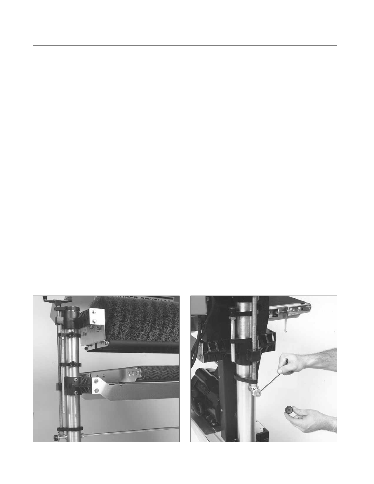
When troubleshooting the height adjustment
mechanism, first check the conveyor table for level
(see page 7). Then test the height adjustment
mechanism (See Fig. 13). If it does not operate
easily, further adjustments may be necessary, as
outlined below. Following these steps should result
in smooth operation.
Readjustment Procedure
1. Loosen the set screws located at the front of the
table support castings (Fig. 3).
2. Lubricate thoroughly by applying penetrating
lubricant to the table support castings where they
contact the column tubes, and to all contact points
of adjusting screws and transfer rod (Fig. 15). Also
apply grease or oil to the miter gears.
3. If the height adjustment feels stiff, check for
misalignment of adjusting screw supports and the
brush support castings which could cause binding
on the adjusting screw (Fig. 5). These castings can
be adjusted by loosening the set screws which
secure them to the column tubes. Realign the
adjusting screw supports by loosening the two set
screws that hold them to the column tubes and
rotate to the proper position.
4. The adjusting screw supports located immediately
below the height adjustment handle and the left
SERVICING YOUR SUPERBRUSH
Fig. 13. Table support casting set screws. Fig. 14. Adjusting miter gears for proper mesh.
Page 17
SERVICING YOUR SUPERBRUSH 17
(outboard) brush support casting (Fig. 15) must
both be set at the proper height along the column
tubes so the height adjusting screws provide for
proper miter gear alignment. Before adjusting these
parts, tighten one set screw in the table support
castings (Fig. 5) to hold the height adjusting screw
in position during adjustment.
Also check to see that the column tubes are centered inside the bore of the table support castings
(Fig. 5). If not, loosen the casting bolts and tighten
the set screws at the front of table support casting to
center the tube. Retighten the bolts and loosen the
set screws.
5. If the height adjustment mechanism feels
rough, check the miter gear (Fig. 14) alignment.
The miter gears can be adjusted on their shafts by
loosening the set screws on the gears. Check and
adjust so that the gear mesh is not too tight or too
loose, and that the gear teeth align with the
opposing gear. Note that the shaft collars located
on the transfer rod should be adjusted to control
the lateral movement of the transfer rod to maintain
accurate miter gear alignment and mesh.
The mesh of the miter gears should be smooth
and even. If not, adjust the gears for good mesh.
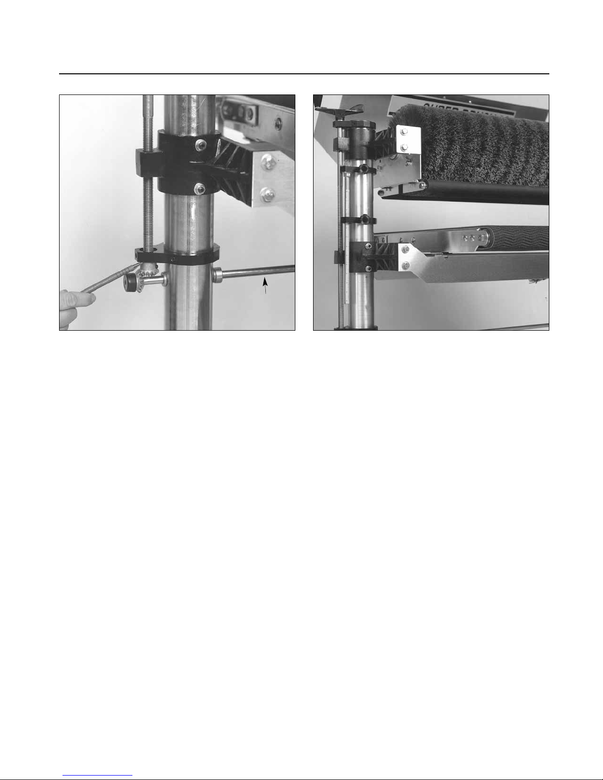
Measure the space between the miter gear and the
adjusting screw support that holds the height
adjusting screw in place (Fig. 15). The distance
should be 1/64˝ or less. If there is excessive space,
move the adjusting screw support to the proper
distance above the miter gear and retighten.
Loosen the set screws in the table support castings
(Fig. 3) and test for smooth operation.
6. Next, check the position of the height adjusting
screw. First raise the conveyor table. Then check
the retaining-clip and washer at the top of the
height adjusting screw on the right (inboard) side,
and under the height adjustment handle on the left
(outboard) side of the machine (Fig. 5). On both
sides, the washer and handle should be snug on the
casting and retaining the washer. If there is a space
between the washer and the casting, tighten one set
screw in each of the table support castings. If one
height adjusting screw is loose, remove the miter
gear from the transfer rod on that side. Turn down
the threaded height adjusting screw rod until it is
snug on the washer. Make sure both sides are snug
on top. Reinstall the miter gear and tighten.
Loosen the set screws in the table support castings
and test for smooth operation.
Fig. 16. Height controls on outboard side.Fig. 15. Miter gear below adjusting screw support.
TRANSFER
ROD
Page 18
18 SUPERBRUSH OWNER’S MANUAL
LEVELING TABLE
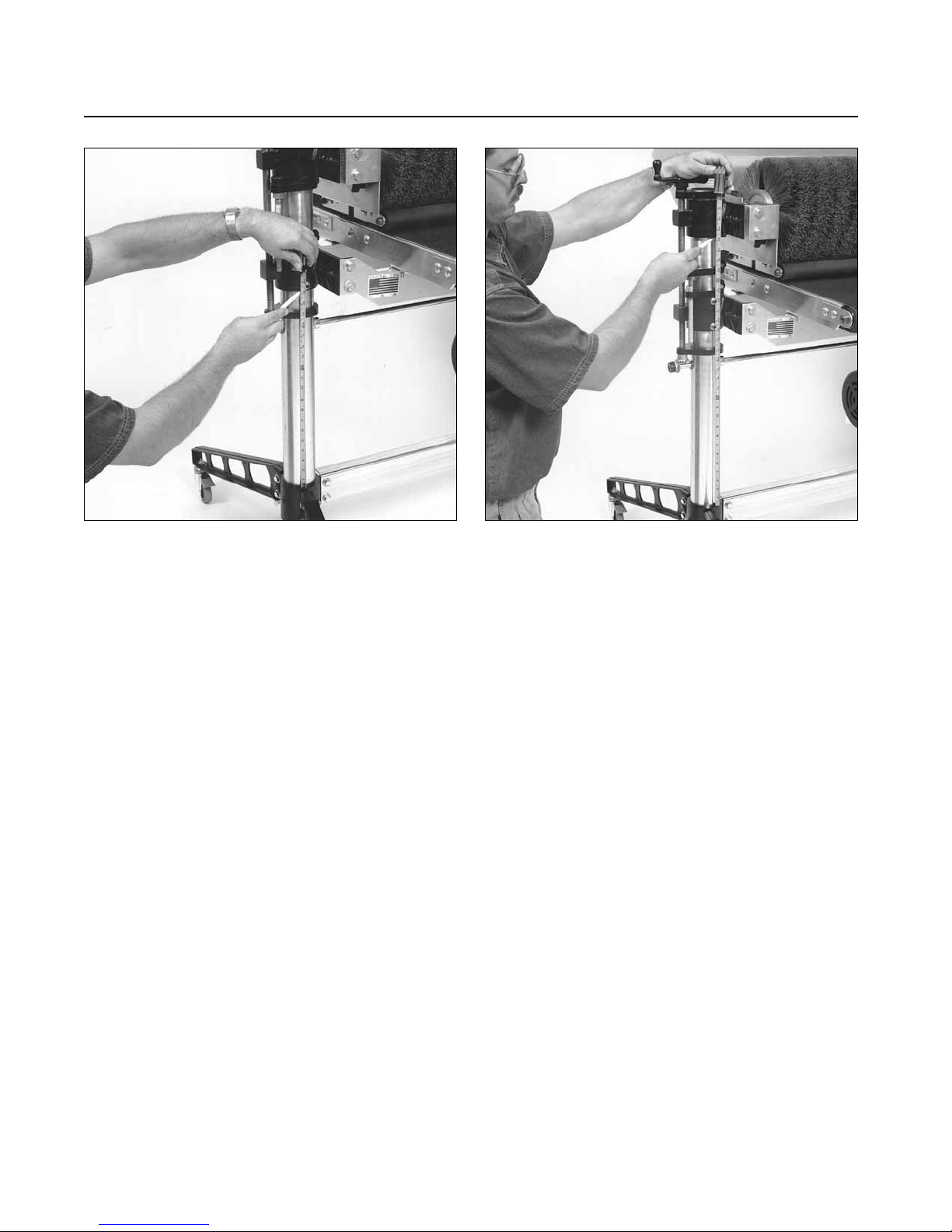
To measure levelness of table, measure the distance
between the top of the base casting (Fig. 17) and
the bottom of the table support castings. This
measurement should be the same for both sides. If
it is not the same, adjust as follows:
Remove the plastic cap from the miter gear (Fig.
14) on the outboard side of the machine. Loosen
the set screw of the miter gear and slide it back to
disengage it from the miter gear of the adjusting
screw. Turn the adjusting screw handle to raise or
lower the outboard side of the table so that the
measurement taken above equals the inboard side
of the table. After adjusting is complete, re-engage
miter gear making sure that miter gear set screw is
aligned with flat on cross bar shaft.
MITER GEAR ALIGNMENT
If height adjustment mechanism does not operate
easily, perform the following checks or adjustments:
1. Loosen set screws located on table support
castings. (Fig. 3).
2. Lubricate thoroughly! Apply penetrating lubricant
to table support castings where it contacts the
column tubes, and to all contact points of adjusting
screws and cross bar. Apply grease/oil to miter
gears.
3. Check miter gear alignment. Check and adjust
gears so that gear mesh is not too tight nor too
loose and that gear teeth align with opposing gear.
The miter gears can be adjusted on their shafts by
loosening the set screws on the gears. Note that set
screws MUST align with flat of shaft. To raise or
lower the vertical miter gears, the adjusting screw
support, located immediately above the gears,
must also be raised or lowered to ride on top of the
gear to maintain adjusting screw position.
If vertical miter gear is raised to its highest
position, then the adjusting screw (Fig. 5) must be
raised, if necessary , to obtain proper gear alignment.
Raise adjusting screws as follows:
Fig. 18. Comparing brush support casting heights.Fig. 17. Adjusting table support castings.
Page 19
SERVICING YOUR SUPERBRUSH 19
Inboard follow screw (right): Loosen and raise
adjusting screw support (Fig. 5).Loosen both set
screws located on front of brush support casting
and raise inboard side of brush, screw and table to
desired height. Retighten set screws of brush support
casting (Fig. 3) and re-position and tighten
adjusting screw support at top of miter gear. The
brush and conveyor table must be re-aligned after
this adjustment. See Leveling Table and Brush
Alignment (page 7).
Outboard Adjusting Screw (left): Loosen and raise
adjusting screw support (Fig. 5) above miter gear.
Tighten set screw at front of outboar d table support
casting. Loosen set screw and disengage opposing
horizontal miter gear. Turn adjusting screw handle
to raise screw to desired height. Re-position
adjusting screw support to bottom of handle.
Re-position adjusting screw support (Fig. 17) to
top of miter gear . Loosen set scr ews of table support
casting (Fig. 3). Re-engage opposing horizontal
miter gear. NOTE: Shaft collars (Fig. 10) located
on the transfer rod should be adjusted to control
lateral movement of the transfer rod to maintain
accurate miter alignment and mesh.
4. Check and adjust for misalignment of adjusting
screw supports (Fig. 5) and brush support castings
which could cause binding on the adjusting screw.
These castings can be slightly rotated by loosening
the set screws which secure it to the inside of the
column tubes. NOTE: The adjusting screw support
(Fig. 5) located immediately below the height
adjusting handle and the outboard brush support
casting, must be set at the proper height along the
column tubes to position the adjusting screws so
that there is proper miter gear alignment. Before
adjusting these parts, tighten one set screw of table
support castings to maintain adjusting screw
position during adjustment.
BRUSH SPEED ADJUSTMENT
If the brush speed adjustment does not operate
easily, perform the following check or adjustments:
1. Loosen set screws located on front of motor
support casting (Fig. 3).
2. Lubricate thoroughly!! Apply penetrating lubricant
to motor support casting where it contacts the
column tubes and to all contact points between
adjusting screw and adjusting screw supports (Fig.
5).
3. Improper alignment of adjusting screw supports
may cause binding on the adjusting screw. Loosen
both set screws on each adjusting screw support to
rotate or adjust screw supports. Note that adjusting
screw supports control both lateral and vertical
movement of the adjusting screw mechanism and
must be adjusted accordingly.
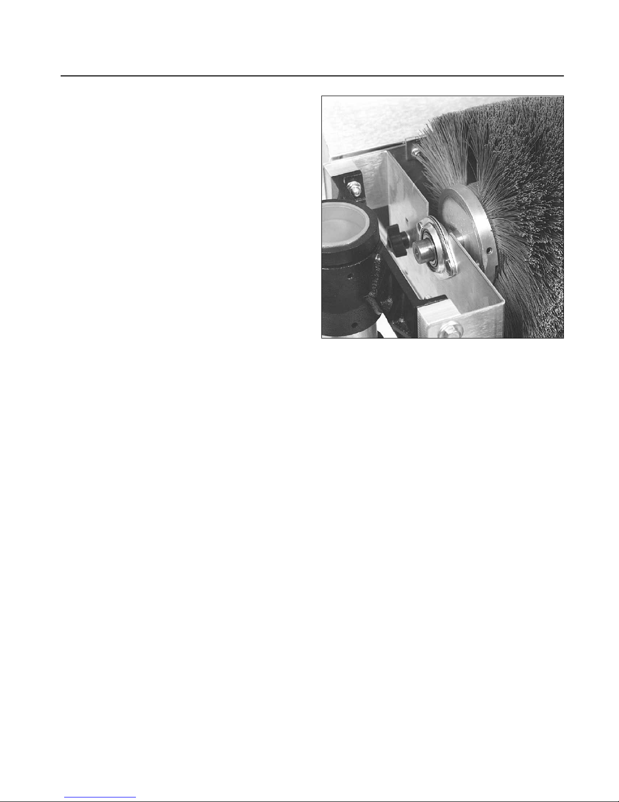
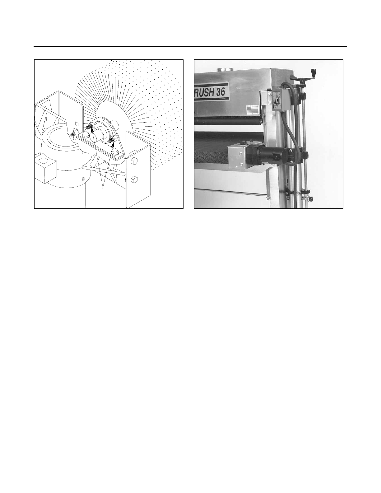
Fig. 19. Removing brush head.
Page 20
20 SUPERBRUSH OWNER’S MANUAL
CHANGING OR REPLACING BRUSH
Changing the brush on the SUPERBRUSH is relatively
simple. To begin, first disconnect power source to
the machine. Lower the motor to its lowest position
using the brush speed control handle. Raise the
motor to its highest position. This loosens the
V-belt tension so the V-belt can be lifted off the
driven pulley, pulled back and placed under the
control handle to hold it out of the way. Loosen
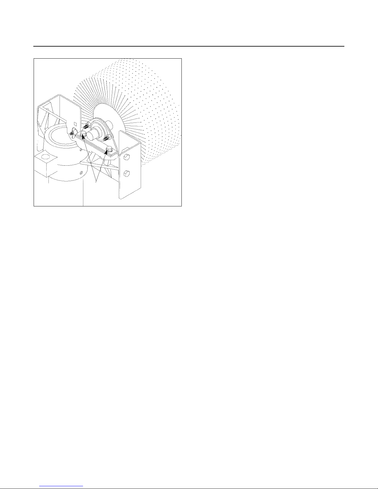
and remove bearing bolts (Fig. 19 and 19A,
depending on model. See also page 23 and Fig.
25.) Lift brush out of machine. Loosen set screws
of bearing collars and pulley. Remove bearings and
pulley and install on replacement brush.
Install replacement brush in machine and center
brush before tightening bearing bolts. Tighten
bearing set screws after bearing bolts are tightened.
Install V-belt on driven pulley and adjust pulley
for proper V-belt alignment before tightening
pulley set screw.
REPLACING CONVEYOR BELTS
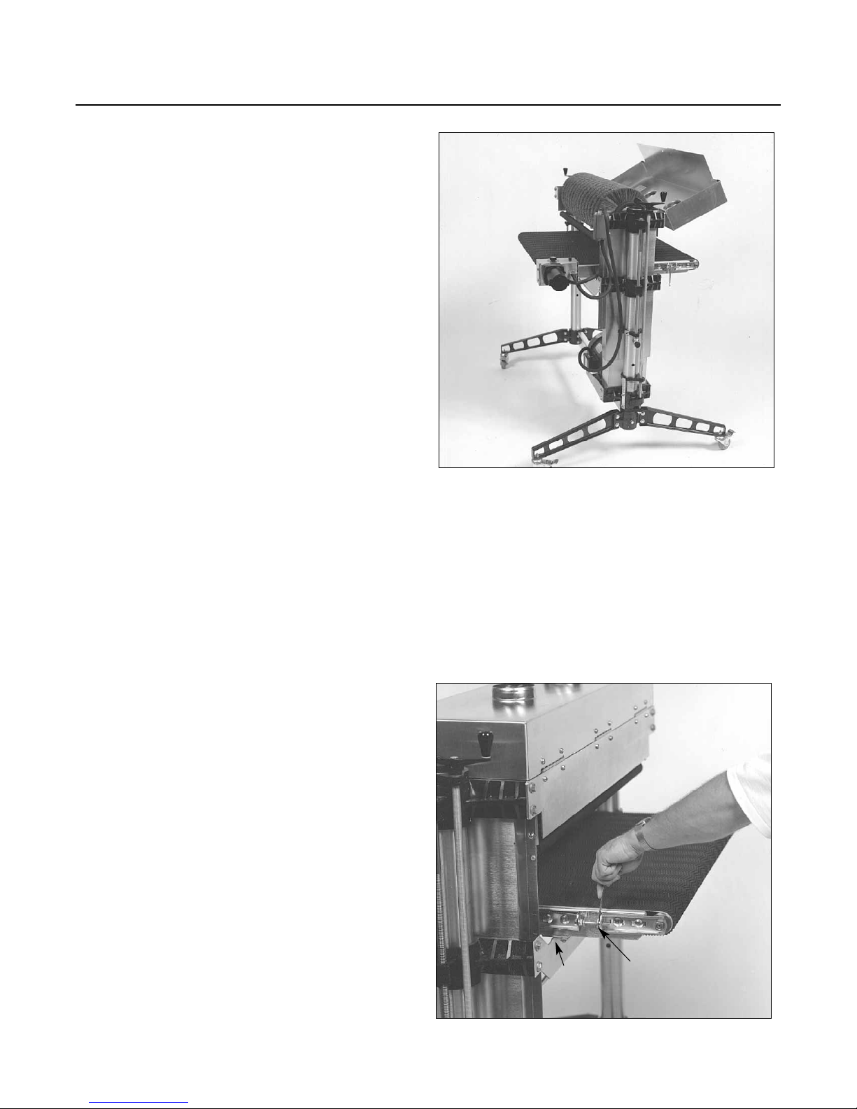
To replace the conveyor belt, the conveyor assembly
must be removed from the machine. Lower the
conveyor table to its lowest position with the
height adjustment handle. Turn off power source
to machine. Place conveyor motor assembly on
top of dust cover (see #3, page 5). Loosen the
conveyor take-up screws (Fig. 21) to relieve belt
tension and slide the driven roller fully inward.
Remove the four bolts that attach the conveyor
assembly to the table mount brackets (see Fig. 21).
Lift the conveyor and remove it from the machine
by sliding the conveyor out toward the front of the
machine. Avoid tearing the belt on any edges
underneath the conveyor bed during removal.
Reverse the procedure for re-installation.
Note: If the conveyor belt continually tracks to
one side of the machine, first try reversing the belt
on the conveyor bed. If this doesn’t remedy the
problem, place a level on the conveyor bed to
make sure the conveyor bed is not twisted. If it is
twisted, see page 7 for instructions on squaring up
the bed. If squaring up the bed does not remedy
the problem, proceed with the steps below:
Step 1. Check the conveyor drive and driven roller
to make sure it is parallel to the surface of the
conveyor bed. To do this, first center the conveyor
belt on the bed. Then lay a straight-edge on the
exposed edge of the conveyor table on the left
(outboard) side, extending it over the drive or
driven roller. Note the distance between the drive
or driven roller and the straight-edge.
Step 2. Now repeat Step 1 on the right (inboard)
side of the conveyor. Compare the measurements
from side to side. If they are not equal, loosen one
of the brackets that hold the drive or driven roller
in place. Tip this bracket until the distance
between the drive roller and the straight-edge are
equal from side to side, then tighten the bracket.
Fig. 19A. Removing brush head (some models).
BRUSH
MOUNTING
BOLTS
Page 21

SERVICING YOUR SUPERBRUSH 21
Conveyor Belt Tension: To adjust the tension of
the conveyor belt, first adjust the take-up screw
nut (Fig. 21) on both sides of the conveyor to
obtain approximately equal tension on both sides
of the belt when taut. Insufficient belt tension will
cause slippage of conveyor belt on the drive roller
during sanding operation. The conveyor belt is too
loose if it can be stopped by hand pressure applied
directly to the top of the conveyor belt. Excessive
belt tension can result in bent rollers, premature
wearing of the bronze bushings or conveyor belt
Conveyor Belt Tracking: Belt tracking adjustments
are made while the conveyor belt is running. After
the proper belt tension is obtained (see above),
turn the conveyor unit on and set it at the fastest
speed setting. Watch for a tendency of the conveyor
belt to drift to one side of the conveyor. To adjust
the belt tracking, tighten the take-up screw nut
(Fig. 21) on the side the belt is drifting toward,
and loosen the take-up screw nut on the opposite
side. Adjusting the take-up screw nuts on either
side of the conveyor allows belt tracking adjustments
to be made without affecting belt tension. Note:
Adjust the take-up screw nuts only 1/4 turn at a
time. Then allow time for the belt to react to the
adjustments before proceeding further. Try to
avoid over-adjustments.
REPLACING V-BELT
To change the V-belt on the SUPERBRUSH, first
disconnect power source to machine.
1. Lower the main motor to its lowest position
using the brush speed control handle. Raise the
motor to its highest position. This will loosen the
V -belt in the driv e pulley so the V-belt can be lifted
off the driven pulley.
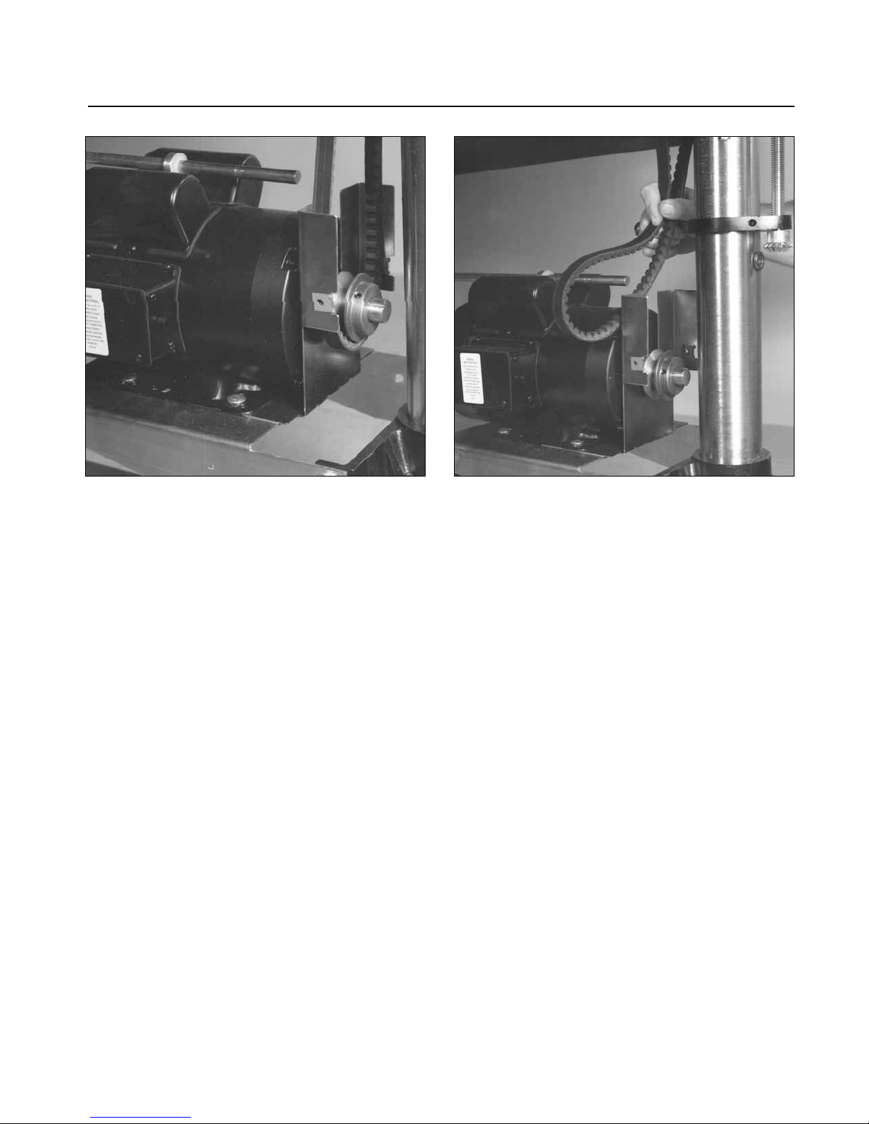
2. Remove the miter gear from the right (inboard)
side of the transfer rod (Fig. 14). (If E clips are
attached to the rod, remove both at this time.)
Now loosen the shaft collar on the left (outboard)
side of the rod, and pull the rod back enough so
the V-belt can be removed. (Make sure to catch
the nylon washer which will drop off the transfer
rod.)
3. Remove the inner half of the pulley guard by
removing the six screws holding the inner half to
the outer half. Remove the inner half of the pulley
guard.
4. Remove the top two bolts holding the top of the
outer pulley guard. The outer half of the pulley
guard can be removed by pulling it up and out
through the head assembly.
5. Remove V-belt from drive pulley. If there is not
enough clearance to remove V-belt loosen the four
bolts securing the main motor to bracket. Note
location of motor before sliding motor out of the
way for ease of reassembly. Note the routing of the
old V-belt: now remove the old V-belt and replace
it with the new V-belt (Fig. 23 and 24).
NOTE: If the V-belt will not fit between the drive
pulley and the brush support casting, loosen or
remove the bolts holding the bearings. Lift brush
enough to allow V-belt to be removed. After
installing new V-belt, retighten bolts.
Machine Reassembly
1. To reassemble the unit after replacing the V -belt,
first reassemble the pulley guards.
2. Place the transfer rod back through the machine
and reinstall the nylon washer. Tighten the shaft
collar (install both of the E clips if so equipped).
Reinstall the miter gear on the transfer rod, making
sure the set screw is centered on the flat of the rod.
3. Adjust the tension on the V-belt by lowering the
motor using the brush speed control handle.
4. Make sure that the V-belt is in alignment. Also
check that all belts are tight before using the
S
UPERBRUSH.
Page 22
22 SUPERBRUSH OWNER’S MANUAL
ROTATING/REPLACING BRUSH BEARINGS
Replacing the permanently lubricated bearings on
the S
UPERBRUSH is a relatively straight-forward
procedure. Bearings should be replaced when they
allow excessive play of the brush, make excessive
noise, or otherwise indicate failure.
Note that if clicking noises in the bearings are a
problem, rotating may be a solution instead of
replacement, as follows:
BEARING ROTATING
Step 1. Loosen the set screws in the bearing collar.
Leave the set screw wrench in one of the set
screws. Then rotate the brush within the bearing
and tighten the set screws (Fig. 19 and 20).
Step 2. If the clicking persists, or if the brush shaft
is tight in the bearing and cannot rotate, then
loosen the two bolts holding the bearing and the
flange for the bearing. Now repeat Step 1. After
the brush is rotated within the bearing, tighten the
flanges first and then the set screws. After the
machine has run for a half hour, stop to check that
the set screws and bearing bolts are tight.
Bearing Replacement:
1. Disconnect power source to the machine.
2. Lower motor to its lowest position using the
RPM adjustment handle. Then raise motor to its
highest position using the RPM adjustment handle. This loosens the V-belt tension so the V-belt
can be lifted off the driven pulley.
3. Raise conveyor bed until the brush rests on
bed.
If replacing both bearings, begin with bearing on
the left (outboard) side.
Replacing Left (Outboard) Bearing:
Make sure power is disconnected to the machine.
1.Remove the outer half of the bearing flange.
Loosen the set screws in the bearing collars and
remove the bearing.
2. If the shaft of the brush is rough from the set
screws, use emery cloth or sandpaper to smooth
down any raised edges. Slide the new bearing on
the shaft, but do not tighten the set screws yet.
3. Install the outer half of the original bearing
flange and tighten the bolts. Then tighten the set
screw in the bearing collar.
If the left (outboard) bearing is the only one that
needs changing, proceed to reassemble the unit.
You can check the brush at this point by lowering
the conveyor bed and spinning the brush by hand.
This will help determine if the inboard bearing
needs to be changed to eliminate noise or excessive
play in the brush.
Fig. 20. Conveyor belt replacement.
Fig. 21. Tensioning and tracking conveyor belt.
CONVEYOR
MOUNTING
BOLTS
TAKE UP
SCREW NUT
Page 23
SERVICING YOUR SUPERBRUSH 23
Replacing Right (Inboard) Bearing:
Disconnect power source to brush.
1. Lower motor to its lowest position using the
RPM adjustment handle. Then raise motor to its
highest position using the RPM adjustment handle.
This loosens the V-belt tension so the V-belt can
be lifted off the driven pulley.
2. Raise conveyor table so brush rests on conveyor.
3. Remove left (outboard) bearing by removing the
two carriage bolts from bearing.
4. Remove the right (inboard) bearing by removing
the two carriage bolts from bearing.
5. Remove V-belt from driven pulley.
6. Lift brush head out from machine.
7. Loosen set screws in bearing collar and driven
pulley and remove from brush shaft.
8. Install new bearing and driven pulley. Do not
tighten set screws at this time.
9. Install brush in machine and center before
tightening bolts. Tighten bearing bolts and then
set screws in bearings.
10. Install V-belt on driven pulley and adjust pulley
for proper V-belt alignment before tightening
pulley set screw.
11. Check the alignment of the brush to the
conveyor system.
REPLACING BRUSH HEAD
1. Lower motor to its lowest position using the
RPM adjustment handle. Then raise motor to its
highest position using the RPM adjustment handle.
This loosens the V-belt tension so the V-belt can
be lifted off the driven pulley.
2. Remove the bearing bolts (Fig. 19, 19A and 25)
and lift brush out of machine. Note: Some models
have two mounting bolts attaching the bearing
housing down into the brush support bracket.
These two bolts can be used to remove the brush
head instead of the bolts through the bearing
flange.
3. Loosen set screws in bearing collars and driven
pulley and remove from brush shaft.
4. Install new bearings and driven pulley. Do not
tighten set screws at this time.
5. Install brush in machine and center before
tightening bearing bolts. Tighten bearing bolts
and then set screws in bearings.
6. Install V-belt on driven pulley and adjust pulley
for proper V-belt alignment before tightening
pulley set screw.
7. Check the alignment of the brush to the conveyor
system. (For instructions on this procedure, see
page 7 of this manual).
8. Lower the conveyor and spin the brush by hand
to make sure the brush shaft is not binding in the
bearing. If the bearings bind, loosen the set screws
Fig. 23. Removing lower guard and transfer rod. Fig. 24. Removing main motor V-belt drive.
Page 24
24 SUPERBRUSH OWNER’S MANUAL
and the bearing flange for one bearing at a time.
Spin the brush within the collar, then tighten the
bolts in the bearing flange and then the set screws.
9. Test-run the S
UPERBRUSH before brushing stock
to check that all is operating properly and is
aligned before brushing good stock. Also, stop the
S
UPERBRUSH after a couple hours of use and check
the bolts and set screws to make sure they are seated
properly.
RR
EEPPLLAACCIINNGGEELLEECCTTRRIICCAALLCCOOMMPPOONNEENNTTSS
To replace either the variable-speed controller, or
the conveyor motor, use the following disassembly
procedure (Fig. 26 and pages 25 and 26):
Disconnect the power supply to the machine.
Next, remove the bottom plate from the control
box. Loosen the set screw in the shaft coupler, and
then remove the four 5/16˝ bolts that hold the
power feed motor assembly in place. Next, remove
the assembly from the machine and turn it upside
down to disconnect the leads from the components
to be removed.
To replace the controller, remove the variable
speed control knob. Remove the nut that holds
the controller in place and pull the controller out
of the housing. Install the new controller, referring
to the correct electrical diagram and reverse the
disassembly procedure.
To replace on/off switch, make sure power is
disconnected to sander. Remove the two screws
holding the front cover of the switch in place.
Disconnect and mark wire leads connected to
switch mechanism. Remove switch from box and
install new switch. Connect wires to new switch
following the wiring diagram and marked wires.
IMPORTANT: Make sure bare wire does not
touch any other wire or the switch box when
connected. Install switch assembly and cover.
To replace the conveyor gear motor, disconnect
the two wire leads from the controller. Also
disconnect the plastic grommet protecting the
wires passing through the housing. Remove the
four cap head set screws that hold the motor to the
housing bracket. Remove the old motor and
install new motor. I nstall the wiring leads according
to the electrical diagram pertaining to the correct
model (See following diagrams).
To replace conveyor fuse (Fig. 4), push and
turn fuse cap 1/8 turn counter clockwise. Pull cap
with fuse from base. Pull fuse from cap and
replace with 3/4 amp fuse (pages 25 and 26).
Place fuse and cap into base, push and turn 1/8
turn clockwise to secure.
Fig. 25. Supporting brushes to remove bearings. Fig. 26. Conveyor motor control box and brush
on/off switch.
BEARING
BOLTS
Page 25
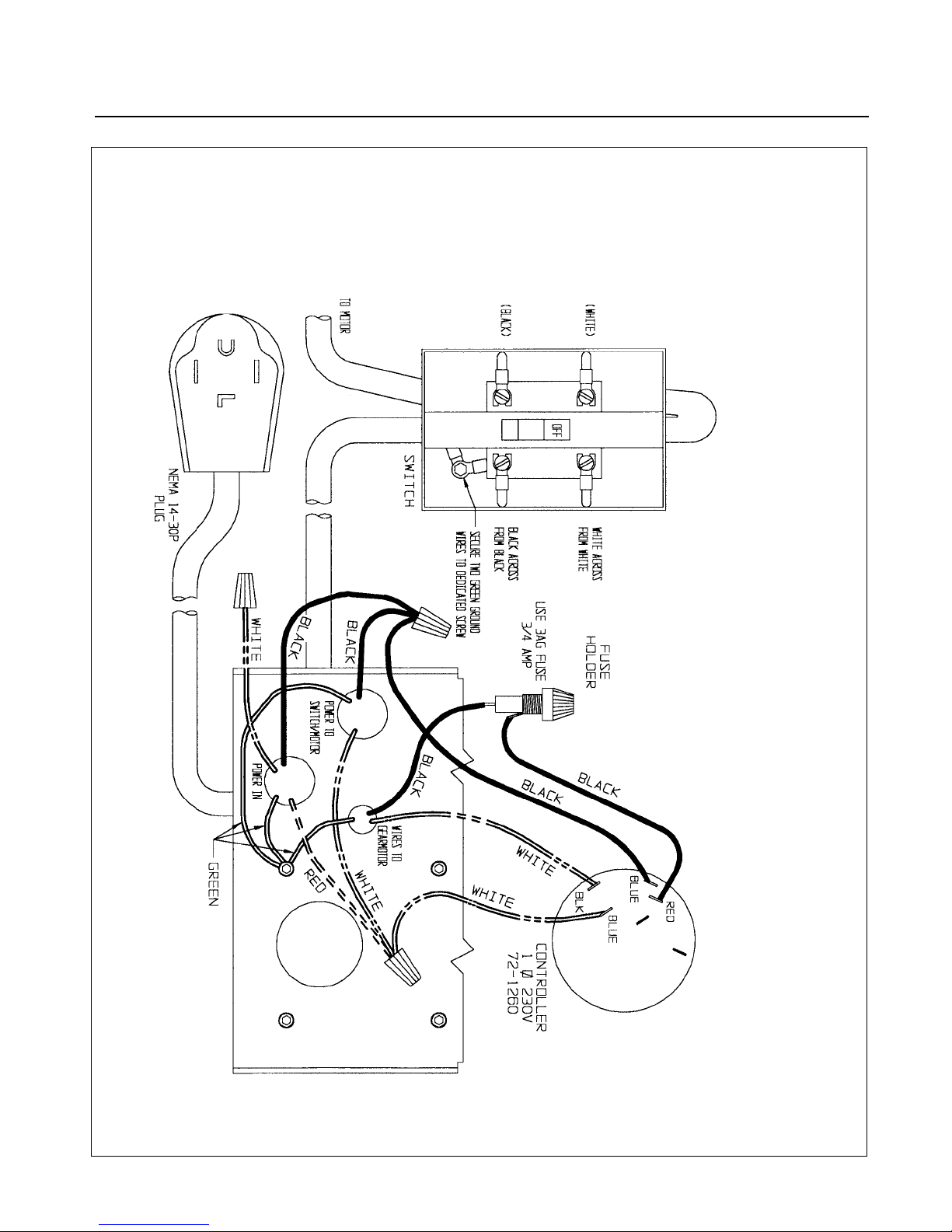
SUPERBRUSH ELECTRICAL DIAGRAM 25
SUPER BRUSH WIRING DIAGRAM
230 VOLT 1 PHASE, 60 HZ
Page 26
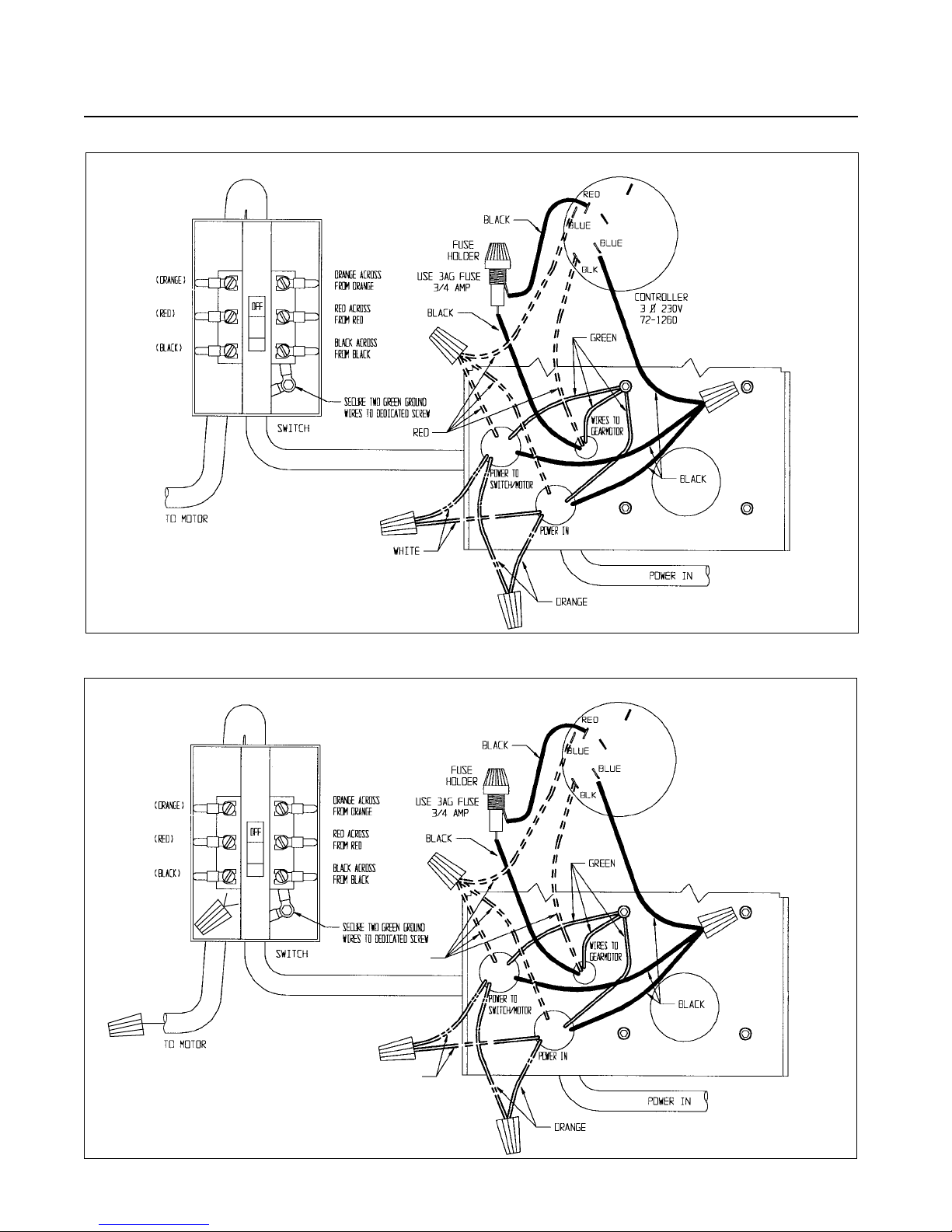
26 SUPERBRUSH OWNER’S MANUAL
SUPER BRUSH WIRING DIAGRAM
460 VOLT 3 PHASE, 60 HZ
SUPER BRUSH WIRING DIAGRAM
230 VOLT 3 PHASE, 60 HZ
RED
WHITE
NEUTRAL
(WHITE)
WHITE
CONTROLLER
3 PHASE 460 V
72-1260
Page 27

SUPERBRUSH SPECIFICATIONS 27
SUPERBRUSH SPECIFICATIONS
SUPERBRUSH 24 SUPERBRUSH 36
Warranty: Two years on parts and labor, limited;
Manufacturer’s warranties on conveyor belts and brush heads.
Dimensions: Model 24: Height: 52˝ Width: 46˝; Depth: 42˝
Model 36: Height: 52˝ Width: 58˝; Depth: 42˝
Dust Hood: Model 24: Steel hood with 4˝ vacuum port, hinged back
Model 36: Steel hood with two 4˝ vacuum ports, hinged back
Brush Speed: Infinitely Variable, 400-1200 RPM.
Brush: See Brushes & Supplies, page 35
Bearings: 1˝ sealed, permanently lubricated, ball.
Conveyor Bed: Steel reinforced with four steel cross sections.
Conveyor Motor: 100 in-lbs. torque, direct-drive
DC motor (1/17 HP).
Infinitely variable from 0 to 15 feet per minute.
Conveyor Belt: Polyurethane, roughtop surface belt, with monofilament
back, included. (Optional abrasive belt available.)
Stand Zinc-plated steel, cast aluminum. Column tubes are
Construction: centerless ground.
Drive Motor: Both Models: 5HP, TEFC; 1,725 RPM; 60 HZ. Continuous Duty
Single phase 208-230V; Optional three phase: 230V or (460V three phase)
Minimum Stock All Models 10˝ without fixtures.
Length:
Height All Models: 3/32˝ per turn; Depth Gauge with locking stop included.
Adjustment:
Stock Thickness 11˝ maximum, typical* with nylon brushes.
Capacity: 12” maximum, typical* with wire brushes.
*can vary depending on specific brush types
Approximate Model 24: 375 lbs.
Shipping Weight: Model 36: 475 lbs.
Tension Rollers: 1 1/2˝ diameter, rubber covered infeed and outfeed rollers
mounted under spring tension, fully adjustable.
Dust Collection: Mandatory for all models.
Page 28

28 SUPERBRUSH OWNER’S MANUAL
Ref.
Description Part Number
Qty./
Number SB24 Both SB36 Unit
Models
1 HANDLE, SWIVEL ASSY 31-0020 2
2 PIN, ROLL 3/16X1 20-0772 2
3 WASHER, 5/8 I.D. OILITE 50-3080 4
4 RING, 5/8 RETAINING 20-0752 1
5 SUPPORT, ADJUSTING SCREW 30-1112 8
6 SCREW, 1/4-20x1/2 SOCKET HEAD SET 10-2804 12
7 SCREW, INBOARD HEIGHT ADJ. FOLLOW 30-1211HR 1
8 CAP, 1” PLASTIC 80-4013 2
9 GEAR, MITER 20-1101 4
10 BUSHING, 1/2 I.D. OILITE ROUND 50-3107 4
11A RPM, BRACKET 40-0670 1
11B RPM, DECAL (NOT SHOWN) 94-1674 1
12 COLLAR, 1/2 I.D. SHAFT 20-1103 2
13 TUBE, COLUMN 30-3044 2
14 SCREW, RPM, MOTOR 30-1209 1
15 MOUNT, MOTOR 30-5103 1
16 NUT, 5/16-18 HEX 12-0003 6
17 WASHER, 5/16 SAE 11-0206 8
18 SCREW, 5/16-18x3/4 BRASS TIPPED SET 10-9906 6
19 BOLT, 3/8-16x1-1/2 HEX HEAD 10-9207 8
20 WASHER, 5/16 WROUGHT 11-9103 20
21 BOLT, 3/8-16x1 HEX HEAD 10-9205 12
22 NUT, 3/8-16 HEX 12-0005 8
23 LEVELING FOOT 20-0655 4
24 SCREW, OUTBOARD HEIGHT ADJ. 30-1212HR 1
25 NUT, 3/8-16 FLANGE LOCK 12-0209 24
26 BASE, COLUMN 30-1101 2
27 BASE SUPPORT BRACKET 40-0230 40-4241 1
28 NUT, 5/8-11HEAVY HEX LOCK 12-8015 1
29 SCREW, 1/2-13x1/2 SOCKET HEAD SET 10-8905 2
30 ROD, TRANSFER 30-1213 30-3117 1
31 SUPPORT BRUSH 30-5206 2
32 BOLT, 3/8-16x1 1/4 HEX 10-9206 4
33 SUPPORT, OUTBOARD TABLE 30-5204 1
34A DEPTH GAUGE ROD 30-1260HR ROD 1
34B DECAL, SCALE 94-1654 SCALE 1
35 NUT, 9/16-12 HEX 12-0011 2
36 LEG 30-1102 4
37 KNOB, LOCKING W/ SET SCREW 81-3132 2
38 CAP, 3Y PLASTIC COLUMN TUBE 80-4015 2
39 SCREW, 5/16-18x3/8 SOCKET HEAD SET 10-2903 4
40 MOTOR MOUNT 40-0106 1
41 SUPPORT, INBOARD TABLE 30-5205 1
42 BRACKET, TABLE MOUNT 40-0025 40-0037 2
CLIP, FRAME (NOT SHOWN) 72-6208 1
BUSHING, 1/2 I.D. OILITE ROUND (NOT SHOWN)
50-3110 2
SUPERBRUSH STAND ASSEMBLY PARTS LIST
Page 29
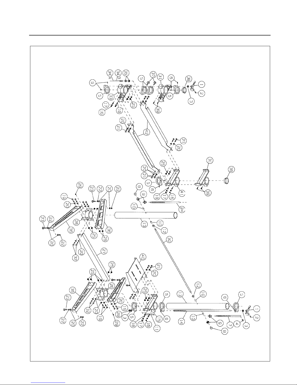
SUPERBRUSH STAND ASSEMBLY 29
Page 30

30 SUPERBRUSH OWNER’S MANUAL
Ref.
Description Part Number
Qty./
Number SB24 Both SB36 Unit
Models
1 DUST COVER 40-0655 40-3655 1
2 HANDLE, DUST COVER 80-2841 1
3 BOLT, HEX 3/8-16X1 10-9205 8
4 WASHER, 5/16 SAE 11-0206 8
5 BRACKET, BEARING MOUNTING (see Fig. 25) 40-0613 2
6 BEARING 50-3086 2
7 SCREW, 1/4-20x1/4 SOCKET HEAD SET 10-8802 4
8 BOLT, 5/16-18x3/4 CARRIAGE 10-1203 8
9 PULLEY, 7˝ (TYPICAL) 50-0701 1
10 SCREW, 5/16-18x3/8 SOCKET HEAD SET 10-8903 1
11 NUT, 3/8-16 FLANGE LOCK 12-0209 8
12 KEY STOCK, 1/4x1/4x1 1/4 20-0764 1
13 SCREW, 1/4-20x1 3/4 ROUND HEAD MACHINE 10-3213 4
14 BRACKET, LEFT SUSPENSION 40-0323 2
15 SPRING, TENSION ROLLER 20-3284 4
16 BRACKET, RIGHT SUSPENSION 40-0326 2
17 BUSHING, 1/2 ID OILITE ROUND 50-3107 4
18 BRACKET, SUSPENSION BASE 40-0322 2
19 NUT, 1/4-20 RETAINING 20-1153 4
21 ROLLER TENSION 30-1218 30-3218 2
22 NUT, 5/16-18 FLANGE LOCK 12-0207 6
23 HINGE 40-0225 3
24 BRACKET, DUST COVER MOUNTING 40-0605 40-3605 1
25 SCREW, 1/4-20x1/2 ROUND HEAD MACH 10-3205 12
26 WASHER, 1/4 INTERNAL TOOTH LOCK 11-0504 12
27 SCREW, 8x1/2 SELF TAPPING 10-3904 2
28 WASHER, 1/4 SAE 11-0205 12
29 NUT, 1/4-20 HEX 12-0001 12
30 NUT 5/16-18 WING 12-9050 4
31 WASHER, 5/16 INTERNAL TOOTH LOCK 11-0505 4
32 BUMPER, DUST COVER 80-1065 2
33 GUARD, BELT COVER 40-0009 1
34 GUARD, BELT, PLATE 40-0010 1
35 GUARD, BELT LOWER 40-0011 1
36 GUARD, BELT, ANGLED 40-0012 1
37 NUT, RETAINING 20-1155 6
38 NUT, RETAINING 20-1157 4
39 SCREW, 10-24x3/8 SLOTTED HEX HEAD 10-3803 10
40 BRUSH See page 35 1
SUPERBRUSH HEAD ASSEMBLY PARTS LIST
Page 31
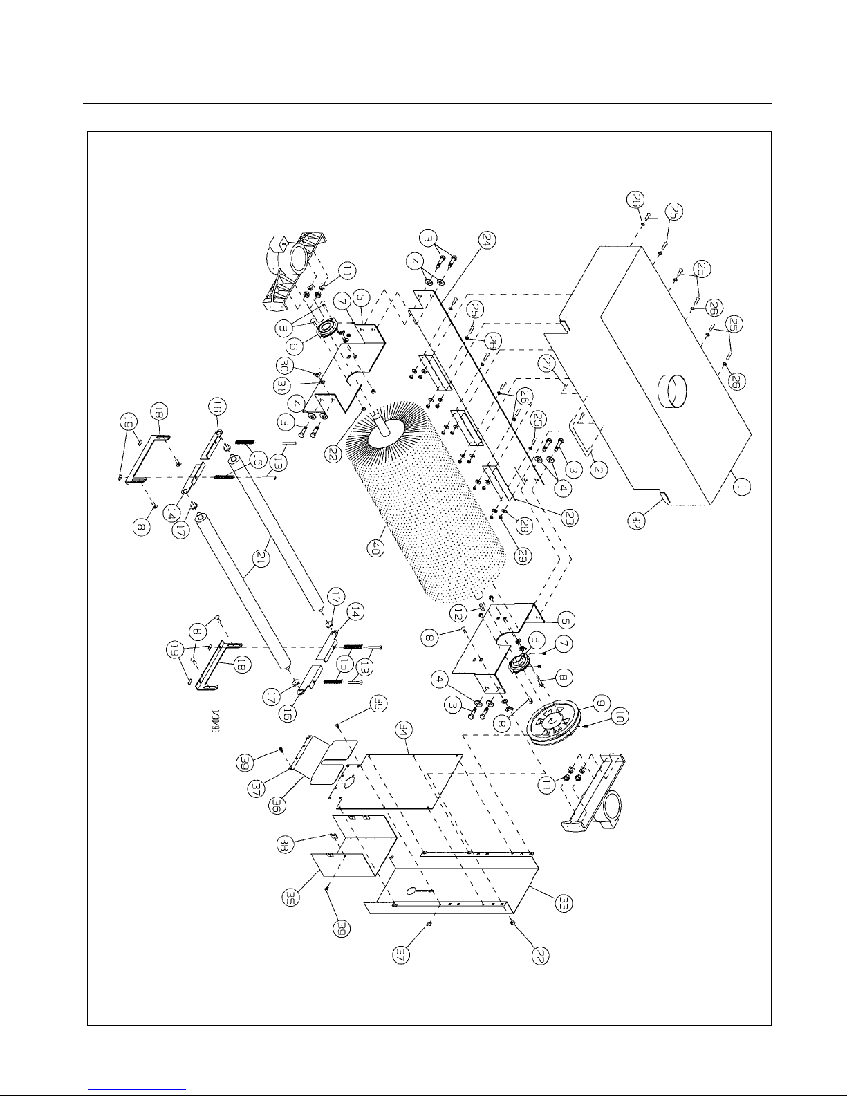
SUPERBRUSH HEAD ASSEMBLY 31
Page 32

32 SUPERBRUSH OWNER’S MANUAL
SUPERBRUSH CONVEYOR & MOTOR PARTS LIST
Ref.
Description Part Number
Qty./
Number SB24 Both SB36 Unit
Models
1 1/4˝-20x1/2˝ ROUND HEAD MACH SCREW 10-3205 3
2 WASHER, 1/4 INTERNAL TOOTH LOCK 11-0504 3
3 SWITCH BRACKET 40-5005 1
4 SWITCH BOX 72-5400-2 1
5 ON/OFF SWITCH 72-5400-1 1
6 1/4˝-20 HEX NUT 12-0001 3
7 LARGE STRAIN RELIEF 72-6104 4
8 CORD SET, SINGLE PHASE, 32˝ 72-5315 1
CORD SET, THREE PHASE, 32˝ 72-5305 1
9 CONTROLLER, 180 V, VARIABLE SPEED 72-1260 1
INCLUDING KNOB, NUT AND DIAL PLATE
10 SMALL STRAIN RELIEF 72-6102 1
11 FUSE HOLDER 72-6202 1
12 180-VOLT GEAR MOTOR 71-1171 1
13 CORD SET, MAIN W/PLUG, SINGLE PHASE 72-5430 1
CORD SET, MAIN, NO PLUG, THREE PHASE 72-5305 1
14 V-BELT 50-2029 1
15 RETAINING CLIP 72-6210 1
16 5/16˝-18x3/8˝ SOCKET HEAD SET SCREW 10-2903 1
17 CORD SET, SINGLE PHASE, 66˝ 72-5315 1
CORD SET, THREE PHASE, 66˝ 72-5305 1
18 KEY STOCK, 1/4x1 3/4 N/A 1
19 FUSE, 3/4 AMP 72-6201 1
21 PULLEY, DRIVE, VARIABLE SPEED 50-0704 1
22 #10-24 RETAINING NUT 20-1157 2
23 LOWER INNER BELT GUARD 40-1000 1
24 5/16˝-18 FLANGED LOCK NUT 12-0207 4
25 3/8˝ WROUGHT WASHER 11-0104 2
26 MOTOR, 5 HP. TEFC, SINGLE PHASE 71-0502 1
MOTOR, 5 HP. TEFC, THREE PHASE 71-1503 1
27 5/16˝-18x3/4˝ CARRIAGE BOLT 10-1203 4
28 5/16˝-18x1/2˝ HEX HEAD BOLT 10-9101 4
29 CONTROL HOUSING 40-5012 1
30 5/16˝-18 RETAINING NUT 20-1159 4
31 SCREW, 5/16-18x1/4 SOCKET HEAD SET SCREW 10-8902 2
32 COUPLING (CONVEYOR) 30-3102 1
33 CONTROL BOX BASE BRACKET 40-4115 1
34 #10-24x3/8˝ SLOTTED HEX HEAD SCREW 10-3803 2
35 #10-24 RETAINING NUT 20-1155 2
36 BOTTOM COVER 40-4116 1
37 RIGHT SIDE RAIL 40-4106 1
Page 33
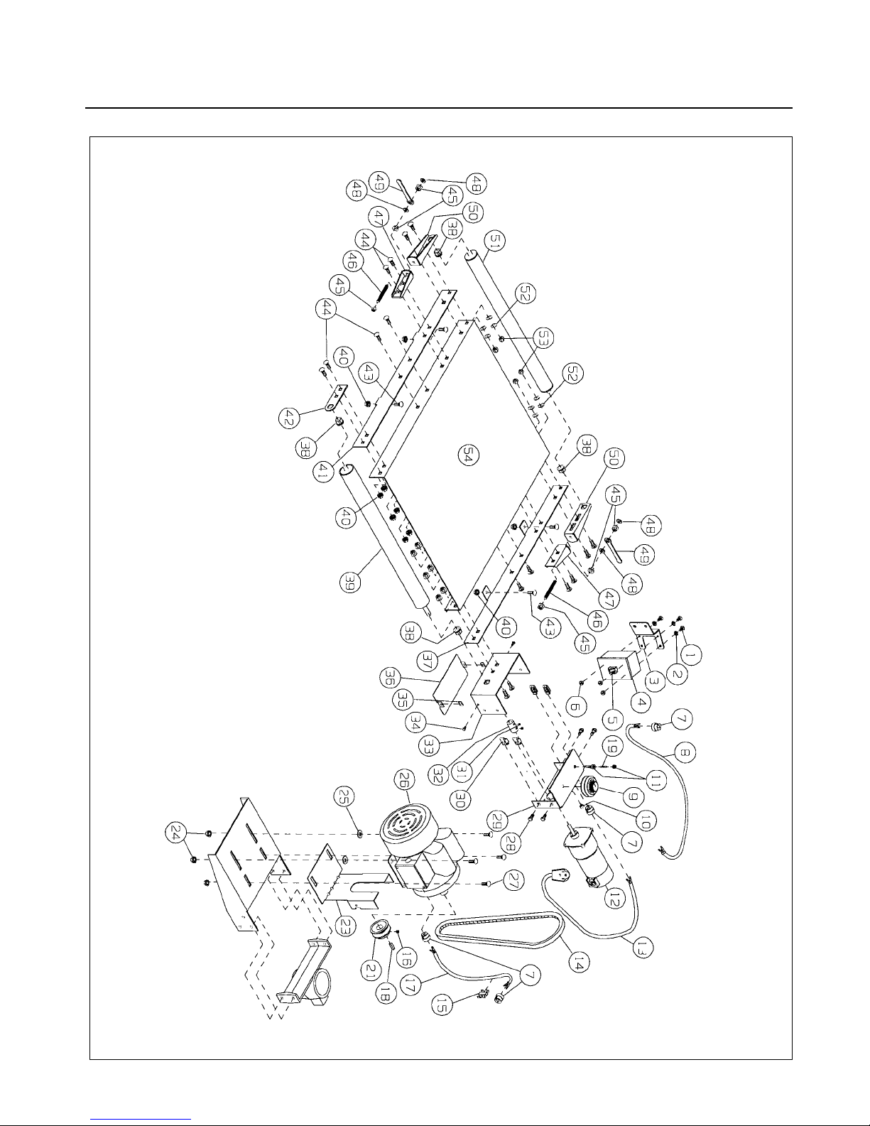
SUPERBRUSH CONVEYOR & MOTOR ASSEMBLY 33
Page 34

34 SUPERBRUSH OWNER’S MANUAL
SUPERBRUSH CONVEYOR & MOTOR PARTS LIST (Con’t.)
Ref.
Description Part Number
Qty./
Number SB24 Both SB36 Unit
Models
38 1/2˝ I.D. SQUARE OILITE BUSHING 50-3109 4
39 RUBBER COVERED DRIVE ROLLER 30-3106 30-3107 1
40 3/8˝ FLANGED LOCK NUT 12-0209 16
41 LEFT SIDE RAIL 40-4105 1
42 ROLLER SUPPORT BRACKET 40-4109 1
43 3/8˝-16x3/4˝ CARRIAGE BOLT 10-1301 4
44 3/8˝-16x1” CARRIAGE BOLT 10-1302 16
45 5/16˝-24 FLANGE NUT 12-0308 6
46 5/15˝-24x3˝ STUD 30-1306 2
47 TAKE-UP BASE BRACKET 40-4107 2
48 5/16˝ SAE WASHER 11-0206 4
49 WRENCH 40-0375 2
50 TAKEUP SLIDE 40-4108 2
51 DRIVEN ROLLER 30-3103 30-3104 1
52 3/8˝ SPRING WASHER 20-1165 4
53 3/8˝-16 NYLON INSERT LOCK NUT 12-8005 4
54 CONVEYOR BED 40-4101 40-4201 1
55 CONVEYOR BELT (NOT SHOWN) 61-1004 61-1007 1
Page 35

SUPERBRUSH BRUSHES & SUPPLIES 35
BRUSHES &SUPPLY CHECKLIST
SUPERBRUSH OPTIONS
BRUSHES FOR THE SUPERBRUSH 24 AND SUPERBRUSH 36
DESCRIPTION QTY.
60 Grit, Nylon/Silicon Carbide bristle, Open or Close wound
80 Grit, Nylon/Silicon Carbide bristle, Open or Close wound
120 Grit, Nylon/Silicon Carbide bristle, Open or Close wound
180 Grit, Nylon/Silicon Carbide bristle, Open or Close wound
220 Grit, Nylon/Silicon Carbide bristle, Open or Close wound
320 Grit, Nylon/Silicon Carbide bristle, Open or Close wound
520 Grit, Nylon/Silicon Carbide bristle, Open or Close wound
Wire, Carbon Steel, Open or Close Wound
Wire, Stainless Steel, Fineset
Fladder style Brush combination, (Head Assembly).
Fladder style Brush combination, (Abrasives only).
Cloth polishing heads
These are just a few types of the dozens of brushes available. Please contact Performax Products Inc. for a complete listing
of brushes and brush material available or to run test samples of your specific application.
SUPPLIES:
ITEM #DESCRIPTION QTY.
98-0130 Caster Set: Heavy duty, roll & swivel lock.
98-0025 Lowrider legs with 4 casters. Lowers machine on casters 5 1/2˝
CONVEYOR BELTS
TYPE 1: 100 grit abrasive surface with reinforced film backing.
TYPE 2: Polyurethane rib-textured surface with monofilament backing.
SUPERBRUSH 24 SUPERBRUSH 36
60-0321 N/A Type 1: Conveyor with 1˝ diameter Drive Roller.
60-0324 60-0337 Type 1: Conveyor with 2˝ diameter Drive Roller.
61-1001 N/A Type 2: Conveyor with 1˝ diameter Drive Roller
61-1004 61-1007 Type 2: Conveyor with 2˝ diameter Drive Roller.
For information on the SuperBrush and supplies
call SuperMax Tools (651) 454-3401 or visit www.supermaxtools.com.
2 YEAR WARRANTY
Limited warranty. We will provide all replacement parts
which are found to be defective in materials or workmanship.
Manufacturers’ warranties on conveyor belts and brush heads.
Page 36

CAUTION:
IMPORTANT SAFETY INFORMATION
FOR SAFE SANDING OPERATION, FOLLOW THESE GUIDELINES:
■ BECOME FAMILIAR WITH THE PROPER OPERATIONAL PROCEDURES
FOR USING THIS MACHINE.
■ ALWAYS BE SAFETY CONSCIOUS WHEN OPERATING THE MACHINE.
■ ALWAYS WEAR EYE PROTECTION WHILE OPERATING THE SANDER.
■ ALWAYS FEED STOCK AGAINST THE ROTATION OF THE BRUSH
■ NEVER PLACE HANDS UNDER THE BRUSH OR DUST COVER.
■ NEVER OPERATE SUPERBRUSH WITHOUT ITS DUST COVER OR
PULLEYGUARD IN PLACE.
■ KEEP HANDS AND CLOTHING AWAY FROM OPERATING BRUSH BELT
AND PULLEYS.
■ ALWAYS MAINTAIN CONTROL OF STOCK TO AVOID KICKBACK;
KNOW HOW TO PREVENT IT.
■ ALWAYS DISCONNECT ELECTRICAL POWER BEFORE PERFORMING
ANY SERVICING OR ADJUSTMENT OF THE MACHINE.
■ DO NOT MODIFY THIS MACHINE: MODIFICATIONS ARE DONE AT
THE OWNER’S RISK AND ALSO WILL VOID THE MANUFACTURER’S
WARRANTY.
■ FOR CUSTOMER SERVICE AND QUESTIONS ABOUT THE OPERATION
OR MAINTENANCE OF THIS MACHINE, PLEASE CALL YOUR
AUTHORIZED SUPERMAX DEALER.
PART NO. 92-2436 A © COPYRIGHT 2006 PRINTED IN USA
 Loading...