

Supermatic SCE2200, SCE3200, SCE3211 Owner's Manual
INSTALLATION, USE AND CARE
MANUAL
RANGES
Part No. 98014246 Rev. A
Covers the following models:
SCE2200
SCE3200
SCE3211
THIS MANUAL CONTAINS IMPORTANT INFORMATION,
READ IT BEFORE FIRST USE OF YOUR RANGE
Printed in M
exico 2003
STM
00196 Rev. A
¡ Congratulations !
Parts and Features
Installation
Gas Supply Connection
How to Use Your Range
Cleaning and Maintenance
Warranty
Identification Format
Authorized Service Centers
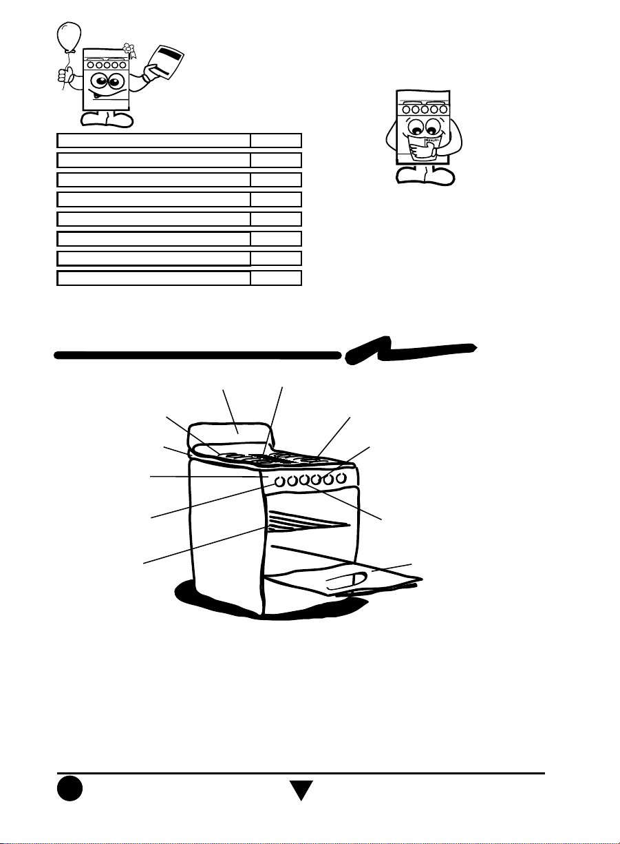
Parts and Features
Backguard
Top Grates
Cooktop
Manifold Panel
Burner Valves
2
3
3
4
6
7
7
8
This range was carefully manufactured with
the latest technical expertise. By purchasing
it, you have received quality; but remember,
quality requires maintenance.
Before you use your range, read the
instructions in this manual, the information
is important for best results in the use of
your range.
Removable Griddle
(Only in Models SCE3200 & SCE3211)
Top Burners
Oven Thermocontrol
Oval Burner Valve
(Only in Model SCE3211)
Oven Rack
Electric Characteristics:
127 V 60 Hz 1,0 A Max.
Oven Door
Install your range in an area that is protected against weather exposure, on a level floor
strong enough to sustain its weight.
Do not allow range to be used by children or unqualified adults.
Provide for adequate maintenance.
Use the range only in home applications. It is not designed for commercial use.
2
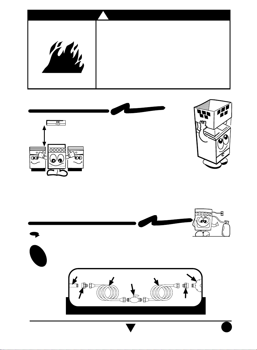
Installation
EXHAUST DEVICE
61 cm
min.
!
WARNING
Fire or Explosion Hazard
Do not allow children to use or play with the range;
keep children away while range is in use.
Keep the range surroundings free of flammable material,
gasoline and other vapors or flammable liquids.
Do not get too close to the flame produced by the
burners or wear loose clothing; your clothes may ignite
if contact by open flames.
Do not use your range to warm rooms, because this is
dangerous.
Failure to do so can result in death, fire or explosion.
Proper installation is your responsibility. A
qualified technician or Service technician must
install this range.
Remove all packing material and put the range
accessories in their places.
Select the best location in your kitchen for your
range, protected from wind and with enough
space to open the oven door.
Do not install cabinetry directly above the range.
If you will install an exhaust device, put it at 61
cm minimum from the range cooktop.
Gas Supply Connection
GAS SUPPLY CONNECTION
To connect the range use the material shown in the bottom figure.
1
3/8" copper pipe with
Gas inlet tube fitting
3/8" brass pipe fitting
Hex. adapter
5/8" flared type nut.
3/8" shut off valve
The material shown is not provided with the range
3/8" copper pipe with
5/8" flared type nut. Necessary
length to reach the gas.
Gas regulator
3/8" brass pipe fitting
Hex. adapter
3
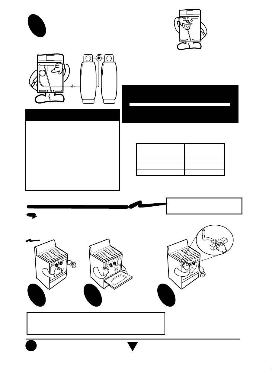
Check with soap solution for leaks.
2
If the installation is not new, you should clean it
in order to avoid the obstruction of orifices and/or pilots.
To make it easier to move the appliance, the
installer should loop the 3/8" copper tubing as
shown in the illustration.
GAS L.P. OPERATING PRESSURE
IMPORTANT
This range is adjusted at the factory
for use with L.P. gas.
To use this range with natural gas,
you must replace the surface and
oven burner orifices, call Servicio
Acros-Whirlpool, the phone number
is shown in the last page. The
technician must make sure that the
connections have no leaks and the
gas pressure in the range is the
same as shown in the charts.
NOTE: To operate this range with natural gas, is
required a kit according to the chart:
Range Model Kit Number
Model SCE2200 98014527
Model SCE3200 98014562
Model SCE3211 98014528
This kit is available at your nearest Authorized
Service Center.
11 inches Water Column
NATURAL GAS OPERATING
PRESSURE
7 inches Water Column
How to Use Your Range
HOW TO ADJUST THE FLAMES
If the range has yellow flames, it may require adjustment to the air
shutters:
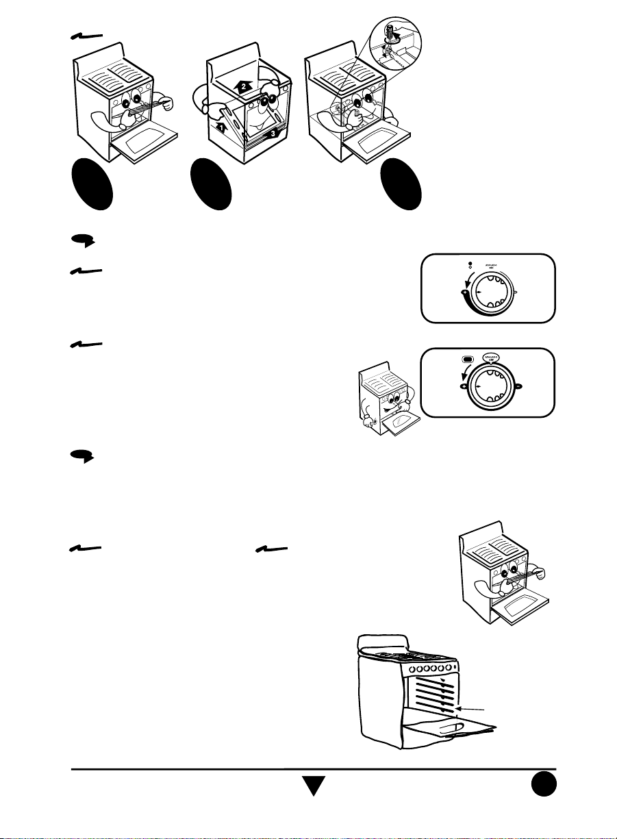
How to adjust the air for surface burners:
Remove the
knobs.
1
NOTE: Because of different altitudes above sea level and variations
in the supply of gas, you may need to adjust the main air intake
to the burners. This will result in a better air-gas mixture and thus
a better operation.
Unscrew the screws
of front and below the
2
manifold panel and
remove it.
NOTE: Do not obstruct the gas
exhaust of the oven or broiler
Adjust the air shutters
individually. Light the
3
burner, then push or pull
the air shutter until you get
a blue flame. Replace the
manifold panel, screws and
knobs.
4
5
MINIM
UM
FLAM
E
MAXIM
UM
FLAM
E
HOW TO TURN ON THE BURNERS MANUALLY
To turn on the surface burners manually:
1.- Light a match and place it close the burner while you
push and turn the knob 1/4 of the way to the maximum
flame position .
How to light the oven burner with thermocontrol, manually:
1.- Open the oven door, light a match and place the
flame at the igniter hole in the front of the oven
tray while you push in and turn the oven knob
1/4 of the way, the burner will light immediately.
2.- Verify that the oven burner has been ignited.
How to adjust the oven burner air shutter:
Remove the
oven rack.
Remove the oven
tray. (See page 6)
1
2
3
OVEN RACK
The oven has 4 different supports for the oven rack, this rack has a stop to avoid droping
from the oven, to change the rack position follow the steps:
To remove the oven rack:
1.- Pull the oven rack until it
stops.
2.- Lift the front part.
3.- Pull it again until it is
released.
To install the oven rack:
1.- Push the oven rack until it
stops.
2.- Lift the front part.
3.- Push it again until it stops.
An extra rack position is provided for special
cooking operations other than baking, such as
roasting, where a large roasting container will
require more heat and therefore need to be closer
to the heat source or oven bottom.
Extra Rack
Position
MINIM
UM
FLAM
E
M
AXIM
UM
FLAM
E
A - Locate the screw on
the air shutter and
loosen it.
B - Turn around the air
shutter.
C - Turn on the oven.
D - Verify that the flames
are blue.
E - If the flames are not
blue, repeat since
step
B, when the
flames are adjusted,
tighten the screw
again.
F - Replace the oven tray
and the oven rack.
 Loading...