

Page 1

User Manual
UT6 series
UHF wireless microphone system
UT6_UM.indd 1 2009/5/7 �� 04:20:31
Page 2

Contents
UT6_UM.indd 2 2009/5/7 �� 04:20:31
Page 3

Contents
1. Preface: ………………… 2
2. Unpacking ………………… 2
3. Receiver Introduction ………………… 4
3.1 Front view ………………… 4
3.2 Rear view ………………… 4
4. Receiver Connections ………………… 6
5. Receiver Operation ………………… 8
6. Receiver Installation ………………… 9
7. Receiver LCD operation ………………… 11
7.1 LCD layout and buttons ………………… 11
7.2 Menu function ………………… 11
7.2.1 Locking and unlocking ………………… 11
7.2.2 G/CH: Display group and channel setting ………………… 12
7.2.3 FREQ: Display frequency in use ………………… 13
7.2.4 SQ: Squelch setting ………………… 14
7.2.5 VOL: Display volume on or mute ………………… 15
7.2.6 NAME: Displaying and naming receiver ………………… 16
7.3 FIC, Frequency Infrared Control ………………… 17
8. Receiver Cautions ………………… 18
9. Receiver Accessories ………………… 19
10. Handheld wireless microphone ………………… 20
10.1 Handheld wireless microphone Introduction ………………… 20
10.2 Inserting batteries ………………… 21
10.3 LCD ………………… 22
10.4 Color coded cover ………………… 23
11. Beltpack transmitter ………………… 24
11.1 Introduction ………………… 24
11.2 Operating ………………… 26
11.3 Wiring for audio input ………………… 27
11.4 LCD ………………… 28
11.5 Batteries exchange ………………… 29
12. Specification ………………… 30
13. Capsules for handheld microphone ………………… 32
14. Microphones for beltpack transmitter ………………… 33
15. Knowing your microphone ………………… 34
Page. 1
UT6_UM.indd 1 2009/5/7 �� 04:20:31
Page 4
1. Preface
2. Unpacking
Thank you for choosing the Superlux
UT6 series UHF wirelss microphone.
This remarkable component has been
engineered to provide superb sound
pick-up with stable transmission
and receiption, as well as providing
outstanding ease of operation.
As this product is provided with a wide
selections of microphones and connection possibilities, we recommend that
before you begin hookup and operation
that you review the contents of this
manual before proceeding.
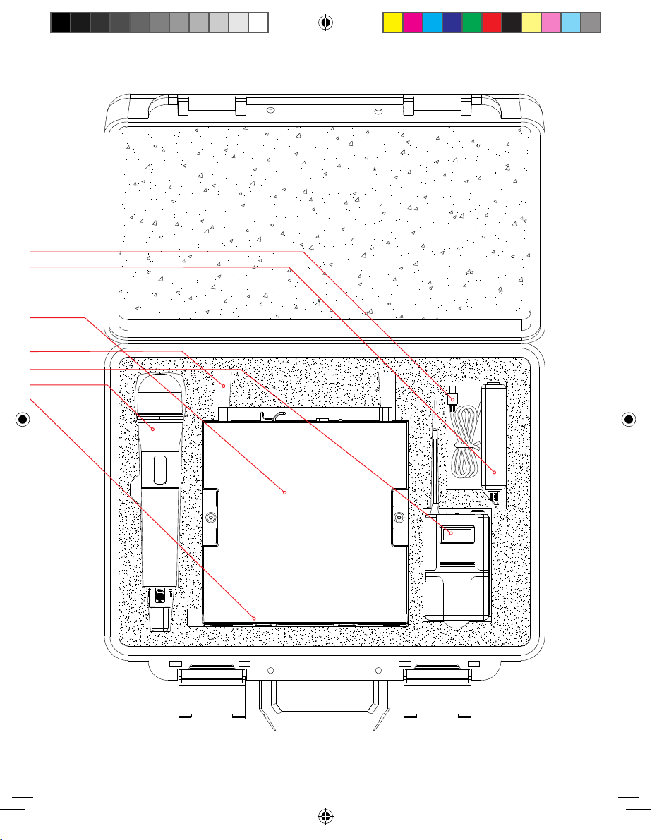
Your package
There are combinations of products for various
demands. There are 2 type of transmitter in this UT6
system, handheld of beltpack. User can include both
in this package, but only one transmitter can operate at
the same time.
For handheld user, there are 4 types of capsules to
choose, 2 dynamics, 1 true condenser, and 1 electret
condenser.
For beltpack user, there are 7 microphones and 1 cable
to choose.
Your package can be any combination. Please verify the
contents with your dealer. Future upgrade with more
components can be easily made by contacting your
dealer.
1 x dual plug cable
1 x power supply
1 x user manual
1 x warranty card
1 x UT6 receiver
2 x antenna (under UT6 receiver)
Optional headworn microphone
Optional UT2 beltpack transmitter
Optional UT4 handheld transmitter
Page. 2
UT6_UM.indd 2 2009/5/7 �� 04:20:31
Page 5
Page. 3
UT6_UM.indd 3 2009/5/7 �� 04:20:34
Page 6
single channel receiver
single channel receiver
3. Receiver Introduction
Front view
Illustration 1
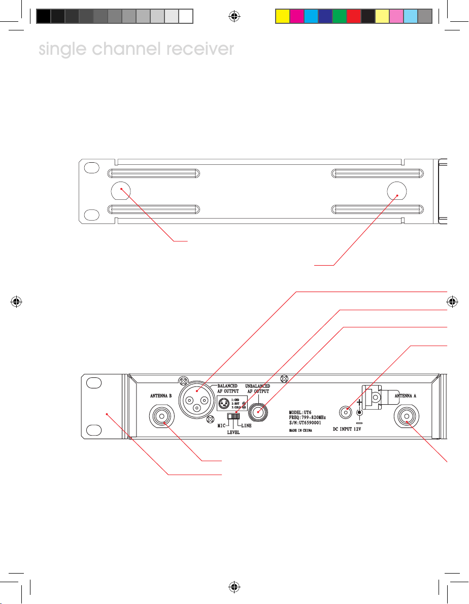
Rear view
Illustration 2
Front panel antenna A socket: for optional
①
antenna extension from rear panel.
Front panel antenna B socket: for optional
antenna extension from rear panel.
Antenna B socket
⑥
Rack mount side panel (optional)
⑤
②
Page. 4
UT6_UM.indd 4 2009/5/7 �� 04:20:34
Page 7
single channel receiver
Power switch: LED indicator lighted when power-on.
Balanced audio output, XLR-3M, microphone level
⑦
Un-balanced audio level switch: Switch between “MIC” or “LINE” level for un-balanced output socket.
⑧
Un-balanced audio output socket: 6.3mm phone jack, level switchable
⑨
⑩
DC power socket: 12VDC power source, center positive.
④
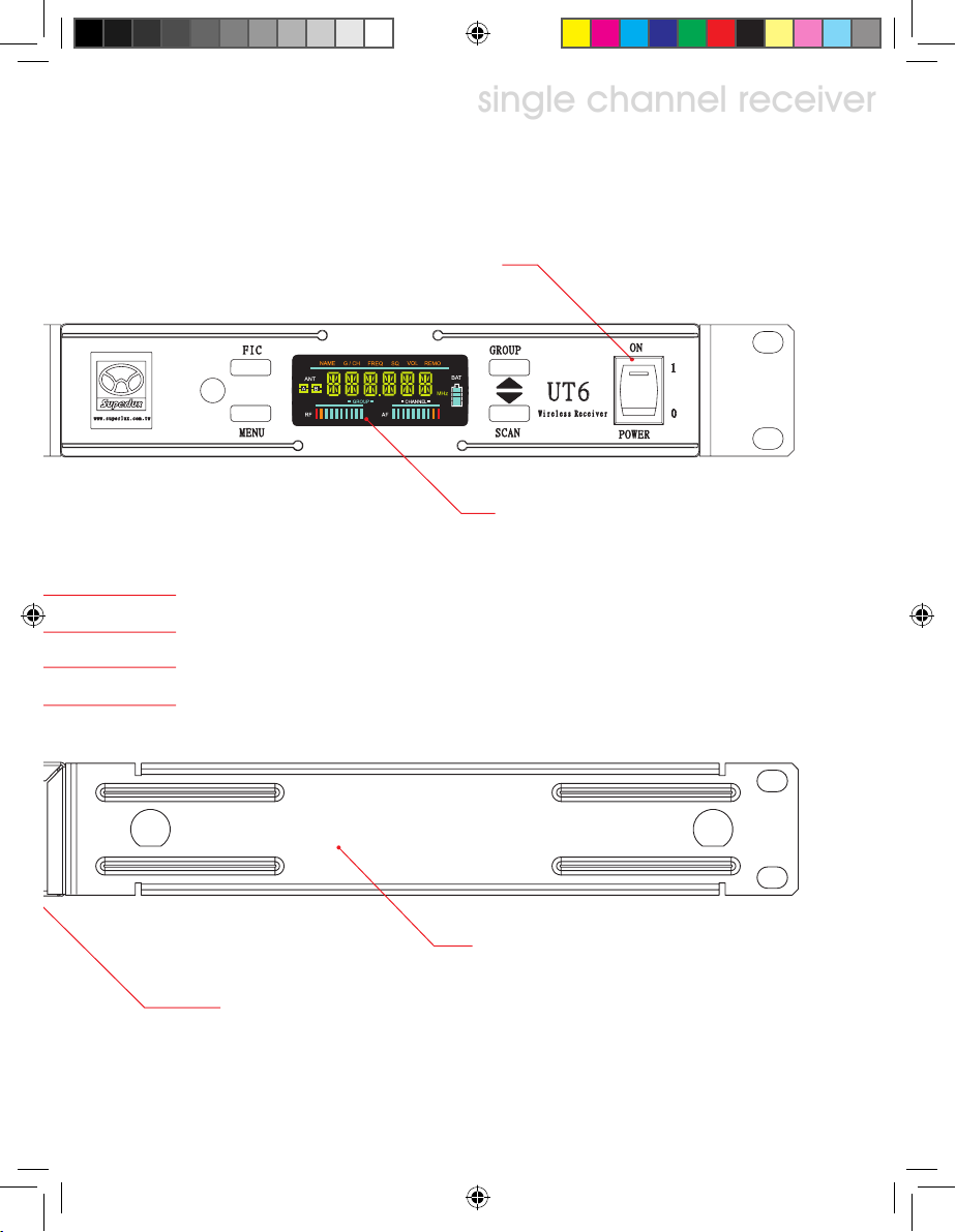
Color LCD display panel
③
Rack mount side panel, 1/2 space width (optional)
⑫
Antenna A socket
⑪
Page. 5
UT6_UM.indd 5 2009/5/7 �� 04:20:35
Page 8
single channel receiver
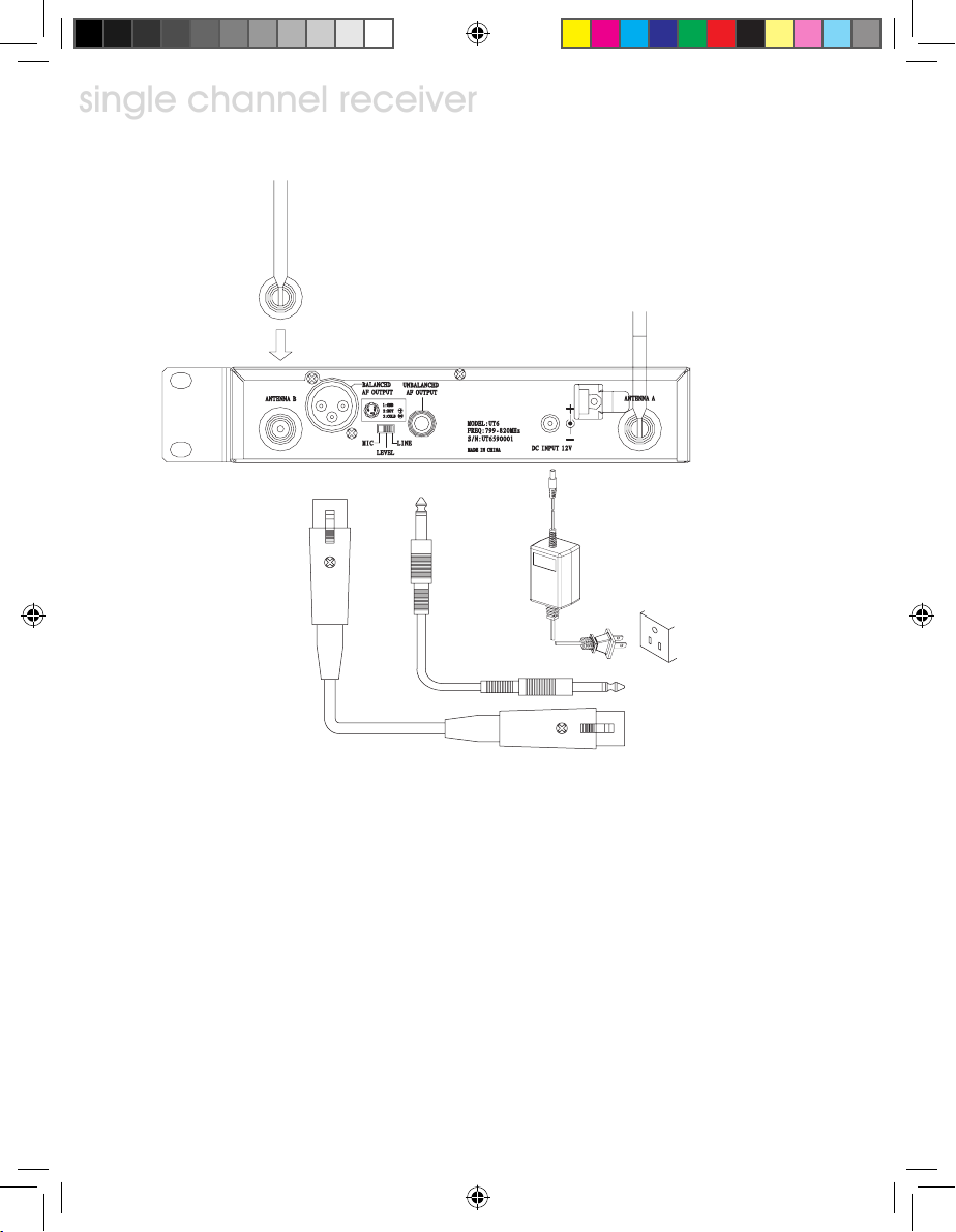
4. Receiver Connections
single channel receiver
Illustration 3
4.1 Connect both antenna to rear panel socket ⑥ and ⑪ as illustration 3.
4.2 Connect power adapter output to receiver ⑩ and plug into power line (Caution:
check power source specification, make sure the power adapter matches the
source spec.
4.3 Audio connections:
4.3.1 Level switch ⑧, when un-balanced output socket is connected to mixers or
amplifiers’ line level input, switch the output level to “LINE” position. When
connected to mixers or amplifiers’ mic level input, switch the output level
to “MIC” position. Mis-match level setting, will result distortion or high
noise. When used with guitar, keep the level at “LINE” position.
Page. 6
UT6_UM.indd 6 2009/5/7 �� 04:20:35
Page 9

single channel receiver
Ground
Signal +
Signal
-
Illustration 4
4.3.2 Un-balanced connection: When receiver and mixer are positioned
at short distance, 6.3mm phone type plugs can be used with unbalanced connection.
4.3.3 Balanced connection: When receiver is located at a remote location from mixer, balanced XLR cable shall be used. Pin 2 hot at
receiver output.
4.3.4 When electric guitar is in used, connect PHONE output to guitar
amp input and level switch to “LINE”.
Page. 7
UT6_UM.indd 7 2009/5/7 �� 04:20:35
Page 10
single channel receiver
5. Receiver Operation
single channel receiver
5.1 Set mixer/amplifier input level to minimum or mute the channel. Turn on the
receiver, the indicator shall be lighted to show the operation status.
5.2 Power up the matched channel transmitter, the RF level indication shall be
lighted.
5.3 Adjust the mixer/amplifier level to optimum and test the microphone/transmitter with normal talking or instrument playing. The AF level indicators shall show
the AF signal.
Notes:
If audio signal doesn’t show or go through the mixer/amplifier, check the signal
chain, connections, level settings...
Wireless microphone level controlled only on mixer/amplfier, the only setting of the
receiver is “MIC/LINE” position.
Page. 8
UT6_UM.indd 8 2009/5/7 �� 04:20:35
Page 11
single channel receiver
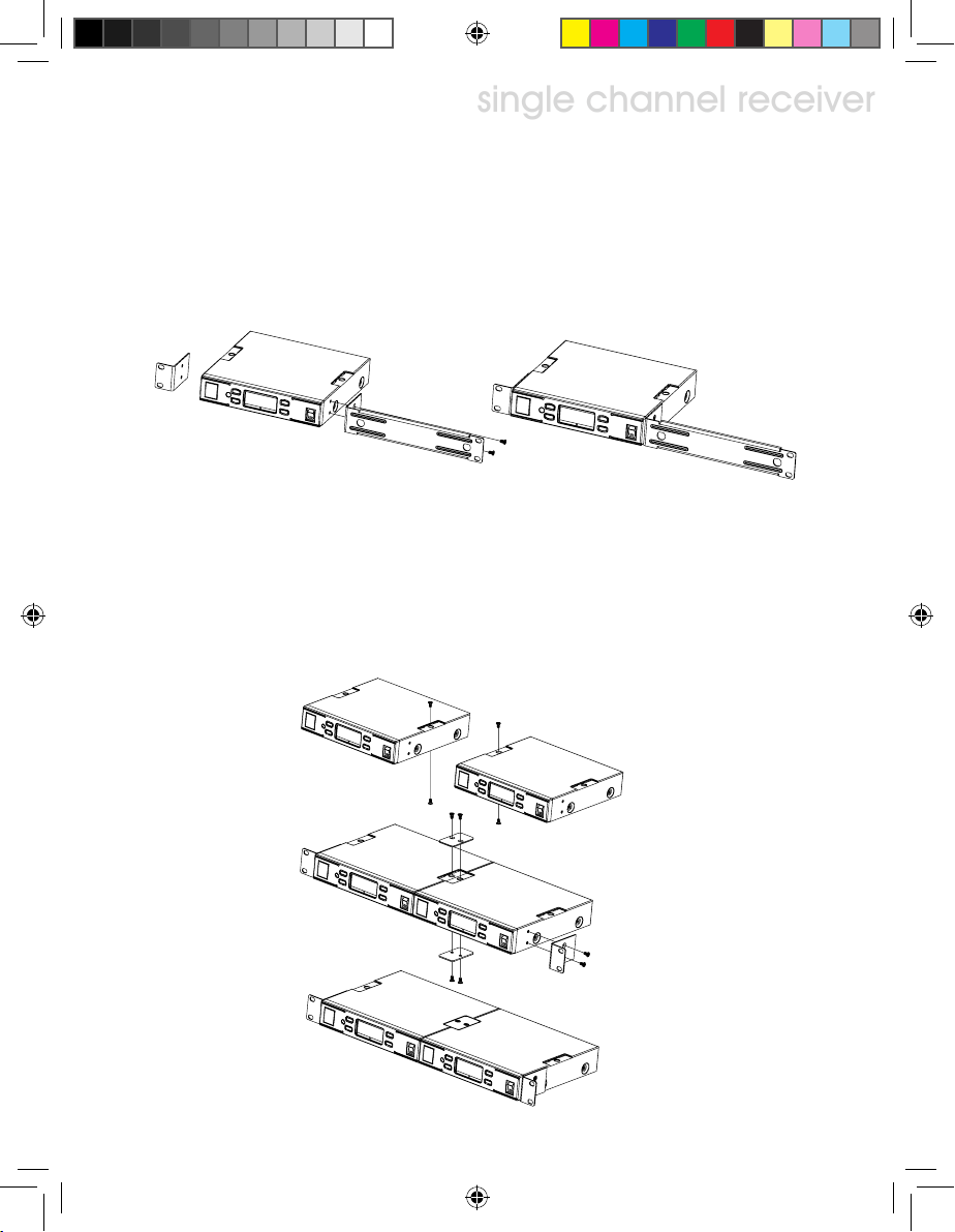
6. Receiver Installation
6.1 Single receiver half width space rack mouting
6.1.1 Mount the rack mouting kit with receiver according to illustration 5.
Illustration 5
6.2 Dual receivers, full width space rack mouting
6.2.1 Unscrew the 4 screws according to the illustration 6.
6.2.2 Mount the connection plate with previous 4 screws to interlock the 2
receivers.
6.2.3 Mount the rack brackets to both ends as illustration.
Illustration 6
Page. 9
UT6_UM.indd 9 2009/5/7 �� 04:20:35
Page 12
single channel receiver
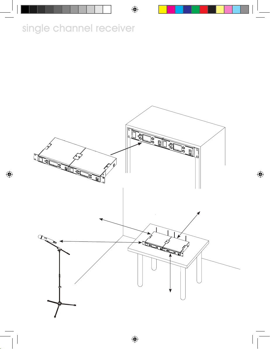
6.3 After the rack mount kit was properly installed, the receiver(s) can be mounted
single channel receiver
into EIA standard rack for 1 space height, as illustrated.
6.4 For best receiption, receiver shall be located at least 1 meter above ground.
Transmitter shall be at least 1 meter away and keep away from noise as illustration.
Illustration 7
Illustration 8
>1M
>1M
>1M
>1M
Page. 10
UT6_UM.indd 10 2009/5/7 �� 04:20:35
Page 13

single channel receiver
7. LCD operation
7.1 LCD layout and buttons
7.2 Menu Function
Menu: To access function menu
By pressing this button, user can go through selections of function:
NAME G/CH FREQ
7.2.1: Locking and unlocking
a. To lock in order to prevent mis-operating, press MENU and hold for more than
3 seconds until LCD shows “LOCK”. At this time, all buttons except “FIC” will
be disable. Receiver operation are now locked.
b. To unlock, press MENU and hold for more than 3 seconds until LCD shows
“UNLOCK”. Receiver are now unlocked.
UT6_UM.indd 11 2009/5/7 �� 04:20:35
SQ VOL
Page. 11
Page 14

single channel receiver
7.2.2 G/CH: Displaying group and channel setting and changing.
single channel receiver
A: GROUP setting steps:
MENU
B: Group setting detail:
a. Press MENU key, select G/CH, LCD displaying 2 double digit number as GROUP and
CHANNEL connected with a dash line.
b. Press GROUP ▲ key once, GROUP double digit flashes indicating ready for setting.
Pressing again, GROUP number will cycle through all selections and CHANNEL
number will show the first in the GROUP. Pressing and hold GROUP ▲ will keep cycling until release. To stop digits flashing and confirm GROUP setting, simply press
MENU or SCAN ▼ .
Page. 12
UT6_UM.indd 12 2009/5/7 �� 04:20:36
G/CH
GROUP
MENU
save
&
exit
Page 15

single channel receiver
C: CHANNEL setting steps:
MENU
D: Channel setting
a. Press MENU to select G/CH functon. Press SCAN ▼ key once, CHANNEL double
digit flashes indicating ready for setting.
b. Pressing SCAN ▼ again, receiver start to scan channels and stop at the first avail-
able channel. If all channels in the group are taken and the receiver keep on scanning, user shall go the another group. Pressing SCAN once or holding, receiver will
keep on scanning until SCAN key released. To stop double digit flashing and confirm
channel setting, press MENU again to complete.
7.2.3 FREQ: Displaying frequency in use
G/CH
SCAN
MENU
save
&
exit
A, Steps:
MENU
B, Operations:
a. Press MENU to select FREQ.
b. This function only display frequency, and user cannot change the frequency.
UT6_UM.indd 13 2009/5/7 �� 04:20:36
FREQ
Page. 13
Page 16

single channel receiver
7.2.4 SQ: Squelch setting and change
single channel receiver
A: SQ setting steps:
MENU
B: SQ setting detail
a. SQuelch range from 01 to 99.
b. Pressing UP ▲ or DOWN ▼ to change value.
c. Press MENU to confirm store and exit.
d. The higher value, the lower receiption sensitivity.
Page. 14
UT6_UM.indd 14 2009/5/7 �� 04:20:36
SQ
01 ↑↓
UP
DOWN
MENU
save
&
exit
Page 17

single channel receiver
7.2.5 VOL: Display Volume ON or MUTE.
A: VOL setting steps:
MENU
B: VOL setting detail
a. Pressing UP ▲ or DOWN ▼ to change from ON to MUTE and cycling.
b. Press MENU to confirm store and exit.
C: Cautions
a. When receiver in muted, AF, ANT A, ANT B level bars will not display.
b. To varify if the receiver is muted, press MENU until VOL selected.
c. If MUTE is displayed, indicating receiver is muted. If ON is displayed, indicating
receiver sending AF signal.
UT6_UM.indd 15 2009/5/7 �� 04:20:36
VOL
MUTE ↑↓
DOWN
UP
MENU
save
&
exit
Page. 15
Page 18

single channel receiver
7.2.6 NAME: Displaying and naming receiver
single channel receiver
A: NAME setting steps:
MENU
A_ ↑↓
NAME
MENU
A ↑↓
UP
save
MENU
DOWN
&
DOWN
UP
B: NAME setting detail
a. NAME up to 6 characters, alphabets upper case, numbers, +, -, *, /, and space.
b. Pressing UP ▲ or DOWN ▼ to edit the flashing digit.
c. Once the desired character is shown, press MENU to accept and go to the next digit.
d. Repeat step b to c until all 6 digits are set, press MENU will save the NAME and exit.
Page. 16
UT6_UM.indd 16 2009/5/7 �� 04:20:36
exit
Page 19

single channel receiver
7.3 FIC function, Frequency IR Control
A: FIC setting steps:
FIC
B: FIC setting detail
a. When the function is set at G/CH mode, press FIC key momentaryly will activating
FIC operation and LCD will display “FIC”.
b. Put microphone with FIC window facing receiver within 30 cm as illustration.
c. As soon as microphone channel was sync with receiver, FIC operation completed
and LCD resume.
d. When FIC operation is activated, if no microphone channel was sync with receiver
within 10 seconds, FIC operation will abort.
FIC
exit
Illustration 9
Page. 17
UT6_UM.indd 17 2009/5/7 �� 04:20:36
Page 20

single channel receiver
8, Receiver Cautions
8.1 DC supplier shall be no less than 12VDC to operate normally, and shall not exceed
15VDC in order not to damage the receiver. Power capacity shall be at least 1A and
regulated.
8.2 Please use supplied antenna to ensure receiption performance.
8.3 Antenna socket provide 8VDC output, please do not short circuit.
Receiver Accessories
RK1 Rack mount kit, for sigle receiver
mounting onto standard 19” width
rack.
RK2 Rack mount kit, for dual receivers
mounting onto standard 19” width
rack.
Page. 18
UT6_UM.indd 18 2009/5/7 �� 04:20:40
RK1
RK2
Page 21

AT0 Dipple 1/4ƛ antenna, omni directional
receiption provides improved signal
captures than the standard antennas.
AT1 Active logrithm directional antenna
provides 6dB antenna gain, and 13dB
amplifier gain.
AT2 Antenna amplifier.13dB gain for
620~960MHz band.
Receiver Accessories
AT0
UDA28 Antenna distribution amplifer. Distributes 1 pair of antenna to 4 receiv-
ers. Works with AT0, AT1, and AT2.
Page. 19
UT6_UM.indd 19 2009/5/7 �� 04:20:40
Page 22

Hand Held Wireless Microphone
10. Handheld wireless microphone
Hand Held Wireless Microphone
10.1 Introduction
Illustration 10
1. Mesh grill: Protecting capsule, and function as pop filter.
2. Capsule: Sound pick up element
3. Upper tube: To hold capsule, grill, transmitter PCB and battery holder.
4. Lower tube: Protecting battery holder and battery.
5. Color coded cover: Protect switch and preventing from mis-operation.
6. FIC window: FIC communcation, auto channel setting.
7. Battery holder: To hold 2 x AA batteries
8. LCD display: To show G/CH, battery capacity, and error info.
9. Power switch: Set to “ON” when in use, set to “OFF” when not in use and save
power.
UTC Color ID cap 8 colors in a pack for UT4.
Page. 20
UT6_UM.indd 20 2009/5/7 �� 04:20:40
Page 23

Hand Held Wireless Microphone
10.2 Inserting batteries
10.2.1 Un screw lower tube ④ to open battery holder.
10.2.2 Insert 2 x AA batteries, positive toward grill into battery holder ⑦
10.2.3 Screw lower tube back to place as illustration.
Illustration 11
p.s. When microphone not in use, switch off the power. If not in use for a pro-long period, please remove
batteries to prevent leaking damage. If re-chargeable batteries were in use, remove them and charge them
accordingly.
Page. 21
UT6_UM.indd 21 2009/5/7 �� 04:20:41
Page 24

Hand Held Wireless Microphone
10.3 LCD
Hand Held Wireless Microphone
10.3.1 GROUP CHANNEL to display operating at pre-defined channel.
10.3.2 CHANNEL to display operating at user defined frequency (through PC setting)
10.3.3 Battery capacity, when reaching 10%, it is time to change new batteries. If battery is
too low, LCD will disply PoFF and switch off to prevent over discharge.
10.3.4 Power off: When switch set to OFF, LCD display “PoFF” to indicating powering down
and automatically switch off. No furthur message on LCD.
100%
Page. 22
UT6_UM.indd 22 2009/5/7 �� 04:20:41
80% 40%
10% 0%
Page 25

Hand Held Wireless Microphone
10.4 Color coded cover
Illustration 12
10.4.1 When the openning of the cover facing the same direction as the power switch, the
switch can be operated freely.
10.4.2 For professional application, to prevent accidentally power switch operation, the
cover can be removed and change direction to cover the power switch as illustration.
10.4.3 When multiple microphones are in use, optional multiple color covers can be
deployed for easier identification.
Illustration 13
Page. 23
UT6_UM.indd 23 2009/5/7 �� 04:20:41
Page 26

Bodypack Wireless Transmitter
11. Bodypack wireless transmitter
Bodypack Wireless Transmitter
11.1 Introduction
Illustration 14
Page. 24
UT6_UM.indd 24 2009/5/7 �� 04:20:41
Page 27

1: Audio input socket: For various microphone inputs
Bodypack Wireless Transmitter
(Refer to Wiring illustration for 5 variations).
2. Power switch: Set to “ON” when in use, set to “OFF”
when not in use and save power.
3. Power indicator: Indicating battery capacity. At the
moment powe switch set to “ON”, indicator flash to
indicate battery is good; If indicator did not flash, indicating batteries were drained or not inserted properlly.
If indicator lighted, indicating batteries low and shall be
changed.
4: Antenna: 1/4λ transmitting antenna
5: Main housing: Housing PCB and parts.
6: LCD
7: FIC window: FIC communication and auto channel set-
ting.
8: Gain adjust: Adjusting input level.
9: GT/MT switch: When electric guitar or line source in
use, set to “GT”. When condenser microphone, wired
microphone in use, set to “MT”. Adjust input level
when set at “MT”.
10: Battery cover: To cover 2 x AA batteries
11: Belt clip: Professional clip to ensure reliable stage
performance as illustrated.
Illustration 15
Page. 25
UT6_UM.indd 25 2009/5/7 �� 04:20:41
Page 28

Bodypack Wireless Transmitter
11.2 Operating
Bodypack Wireless Transmitter
11.2.1 Press both side latches of battery cover and open.
GT/MT switch and gain adjustment can be operated.
11.2.2 Switch on the transmitter, the battery indicator shall
flash to indicating batteries is still good. If indicator did
not flash, indicating batteries drained or not properlly
inserted. If indciator maintain lighted, batteries are low
and shall be changed.
11.2.3 Set gain adjustment at optimum position (switch to
GT when use with electric guitar, and this adjustment
provide limit trimming.).
11.2.4 Plug in the connector as indicated direction, and locking by screwing the holding ring.
Headworn or miniature microphones
Align the plug to
the key position.
Illustration 16
Page. 26
UT6_UM.indd 26 2009/5/7 �� 04:20:41
Page 29

Bodypack Wireless Transmitter
11.3 Wiring for audio input
11.3.1 Wiring 2-conductor electret microphone
11.3.2 Wiring 3-conductor electret microphone
11.3.3 Wiring dynamic microphone
11.3.4 Wiring electric guitar
bias resistor
Illustration 17
Page. 27
UT6_UM.indd 27 2009/5/7 �� 04:20:41
Page 30

Bodypack Wireless Transmitter
11.4 LCD
Bodypack Wireless Transmitter
11.4.1 GROUP CHANNEL to display operating at pre-defined channel.
11.4.2 CHANNEL to display operating at user defined frequency (through PC setting)
11.4.3 Battery capacity, when reaching 10%, it is time to change new batteries. If battery is
too low, LCD will disply PoFF and switch off to prevent over discharge.
11.4.4 Powering off: When switch set to OFF, LCD display “PoFF” to indicating powering
down and automatically switch off. No futhure message on LCD.
100%
Page. 28
UT6_UM.indd 28 2009/5/7 �� 04:20:41
80% 40%
10% 0%
Page 31

Bodypack Wireless Transmitter
11.5 Changing batteries
11.5.1 Press both side latches of battery cover and open it.
11.5.2 Remove the batteries as illustration.
11.5.3 Inserting 2 x AA batteries as indicated polarity into battery holder as illustration.
11.5.4 Latch the battery cover in position.
Illustration 18
Note: When microphone not in use, switch off the power. If not in use for a pro-long period, please remove
batteries to prevent leaking damage. If re-chargeable batteries were in use, remove them and charge
them accordingly.
Page. 29
UT6_UM.indd 29 2009/5/7 �� 04:20:41
Page 32

Specification
12. Technical Specifications
12.1 Receiver
Frequency Range Refer to the frequency table
Carrier Mode PLL synthesized
Channels 99
Space between chennels 125KHz
Frequency Width 24MHz
Carrier stability ±5ppm≤10KHz
Image interference ratio >70dB
Audio frequency response 50Hz~18KHz
Signal to noise ratio >105dB
T.H.D. ≤0.5%@1KHz
Maximum output Balanced -14dBV/100Ω, Unbalanced -4dBV/5KΩ
Function display LCD
DC power input 12~18V, 0.5A
AC power adapter 100~240VAC, AC/DC converter, 1.25A
12.2 Handheld Transmitter
Frequency Range Refer to the frequency table
Carrier Mode PLL synthesized
Channels 99
Space between chennels 125KHz
Frequency Width 24MHz
Carrier stability ±0.005%
Maximum deviation ±48KHz
Harmonic radiation <-60dBc
Transmittion power 20mW
Frequency setting Infrared control by receiver
Dynamic range >110dB
Function display LCD
Power consumption ≤100mA@3V
Power source 2 x UM3, (LR6, AA) batteries
Page. 30
UT6_UM.indd 30 2009/5/7 �� 04:20:41
Page 33

12.3 Beltpack Transmitter
Frequency Range Refer to the frequency table
Carrier Mode PLL synthesized
Channels 99
Space between chennels 125KHz
Frequency Width 24MHz
Carrier stability ±0.005%
Maximum deviation ±48KHz
Harmonic radiation <-60dBc
Transmittion power 20mW
Frequency setting Infrared control by receiver
Dynamic range >110dB
Function display LCD
Power consumption ≤100mA@3V
Power source 2 x UM3, (LR6, AA) batteries
Page. 31
UT6_UM.indd 31 2009/5/7 �� 04:20:42
Page 34

521S
1000 Hz
Capsules for handheld
842ORP
C832ORP
PRA3 83
0º
90º
125º
135º
180º
D108A
0
8
1
A
D
10KHz
1KHz
100Hz
2KHz
250Hz
8KHz
500Hz
2
4
P
8
O
T
250 Hz 2000 Hz
500 Hz
1000 Hz
2
3
O
8
C
R
P
250 Hz 2000 Hz
500 Hz
1000 Hz
2
5
1
S
4000 Hz
8000 Hz
4000 Hz
8000 Hz
3mm
25mm
50mm
0.6M
dB
10
0
-10
-20
20 50 100 200 500 100 0 2000 500 0 1000 0 20000 H z
Microphones for beltpack
8
3
3
A
R
P
250 Hz 200 0 Hz
4000 Hz
500 Hz
8000 Hz
1000 Hz
Page. 32
UT6_UM.indd 32 2009/5/7 �� 04:20:43
Page 35

ARP 2 0
03ARP
A01E
B01E
B815OW
A21E
Microphones for beltpack
A
2
0
R
P
3
A
0
R
P
0
A
1
E
0
B
1
E
0
5
45 45
10
15
20
25
90 dB
135 1 35
180
250 Hz 2000 Hz
500 Hz
1000 Hz
250 Hz 2000 Hz
500 Hz
1000 Hz
1000 Hz
90
4000 Hz
8000 Hz
4000 Hz
8000 Hz
1000 Hz
2
A
1
E
5
1
O
8
W
WO-5 18BD/ XLR low f reque ncy rol l-off
zH 521 zH 0002
zH 052
zH 0004
zH 005
zH 0008
zH 0001
Page. 33
UT6_UM.indd 33 2009/5/7 �� 04:20:49
Page 36

Knowing your microphone
Superlux provides variety selection of microphones for professionals and amatures. To know
your microphone is the first step to successful result.
Type of transducer
Condenser
Extremely light weight diaphragm, very sensitive to
sound. Very small versions available for hiding applica-
tions. High performance condenser microphones are
regarded as standard equipment of recording studios for
extreme detail capturing. Operates with power, such as
phantom or battery.
Dynamics
Durable and simple structure, operates in all kinds of
environments. A good dynamic microphone is capable to
operate at very high sound pressure level without distor-
tion. Due to structure limit, dynamics cannot be built as
small as condenser, but dynamics doesn’t require power
to operate.
Powering microphone
Condenser microphones work with power. Professional wired microphone standard is 48VDC phantom power. Some
microphones work with lower voltage as low as 1.5VDC, such as battery power model. CMH8CH/BH/AH work with
48VDC phantom only. Please make sure your sound system provide adaquate power to the microphone.
Wireless system supplies proper power to the capsule. User do not need to consider the power issue.
About Frequency Response
Flat
Suitable for working at controlled environment, or
for acoustic measurements. Although people persuit
flatness, but for none-professionals, it is a challenge to
makes it works as expectation.
Variable response
Incorporating switchable filters to elliminates interfer-
ence, such as sub-sonic filter to cut air-conditioner
and floor vibrations. And allows full flat when used in
controlled environment.
Popular curve response
Based on years of practical experience of pro users.
There are curves to be build for various applications,
so that it is very simple to use the microphone for the
purpose. Limiting bandwidth, and emphasing are typical
skill.
Page. 34
UT6_UM.indd 34 2009/5/7 �� 04:20:49
Page 37

Directivity
Select or set the directivity of your microphone for stereo recording, for various music instrument, vocal, speech, and environmental sound pick-up. Pair of spaced omni for A/B stereo,
pair of near coincident cardioid for ORTF, and pair of coincident figure-8 at 90° setting for
Blumlein stereo.
Omni
Equal sensitivity to all direction, so that the microphone
doesn’t need to pointing toward the sound source. Low
handling and wind noise. Welcome by news gathering,
and music recording applications.
Super Cardioid
Narrower than cardioid pattern. Suitable for multiple
microphone setup. Least sensitive angle pointing toward
side to rear where most stage monitors are located.
Same proximity effect as cardioid microphone.
Shotgun
Based on interference tube theory, to achieve highest
axial signal pick-up and rejects off-axis sound as much
as possible. Due to poor wind noise rejection, suitable
wind screen shall be used at outdoor.
Cardioid
Picks up most signal on axis. Rejects side and picks up
least to the back. Suitable for live sound re-inforcement.
Apparent proximity effect and most singer likes to take
this bass boost advantages which is not good for speech.
Figure 8, bi-directional
Equal sensitive to both ends, and rejects the sides. Good
to noisy environment to reject distant noise and low
frequency. Also a good choice for stereo recordings, such
as Blumlein. Typical pressure gradient characteristic.
CMH8CH polar variation
Double diaphragm structure with cardioid acoustic nature,
CMH8CH can be set at OMNI, Cardioid, and Figure-8
polar mode.
Page. 35
UT6_UM.indd 35 2009/5/7 �� 04:20:49
Page 38

Distance to source
Close miking or distant miking sound very differently. Vocal recording or live performance
practice close miking mostly. Suitable proximity effect is one desired target, and lower feedback problem is another factor for live sound application.
While distant miking is common practice for recording, especially stereo pair recording with
large group of performers, such as orchestra or choir.
Distant miking generally picks up less bass section with pressure gradient type of microphone
(cardioid, figure-8, shotgun...) due to acoustic nature and lack of proximity effects.
Rich bass with distant miking can be recorded with pressure type of microphone (Omni),
which performs the same frequency response with close or distant pick-up.
Mounting the microphone
Pressure gradient microphone is very sensitive to vibration. Suitable shock mount for high performance microphone is necessary for extreme low noise recording. Sturdy stand can set the
microphone excatly at the sweet spot and keep it there. Choose heavy duty microphone stand
for studio condenser microphone which weights much more than handle microphone.
Superlux provides wide range of microphone stands for various demands. Big Foot Willie
is specially developed for large condenser microphones that able to support 2 large microphones with stereo bracket for single point stereo recording.
Extension foot on all the ‘E’ versions serve to mount heavy studio microphone in limit space
live sound applications.
Maintainence
Condenser microphone shall be kept in low humidity environment for best sound performance.
Store the condenser microphones in air-conditioned room or dehumidifier to keep away form
moisture. Clean air is another important factor. Keep away from smoking environment to avoid
tar residuals
Page. 36
UT6_UM.indd 36 2009/5/7 �� 04:20:50
Page 39

Page. 37
UT6_UM.indd 37 2009/5/7 �� 04:20:50
Page 40

Tel: +886-2-26931323
Fax: +886-2-26938990
E-mail: sales@superlux.com.tw
superlux.tw
Page. 38
UT6_UM.indd 38 2009/5/7 �� 04:20:50
 Loading...