

Page 1
SF112A
SF115A
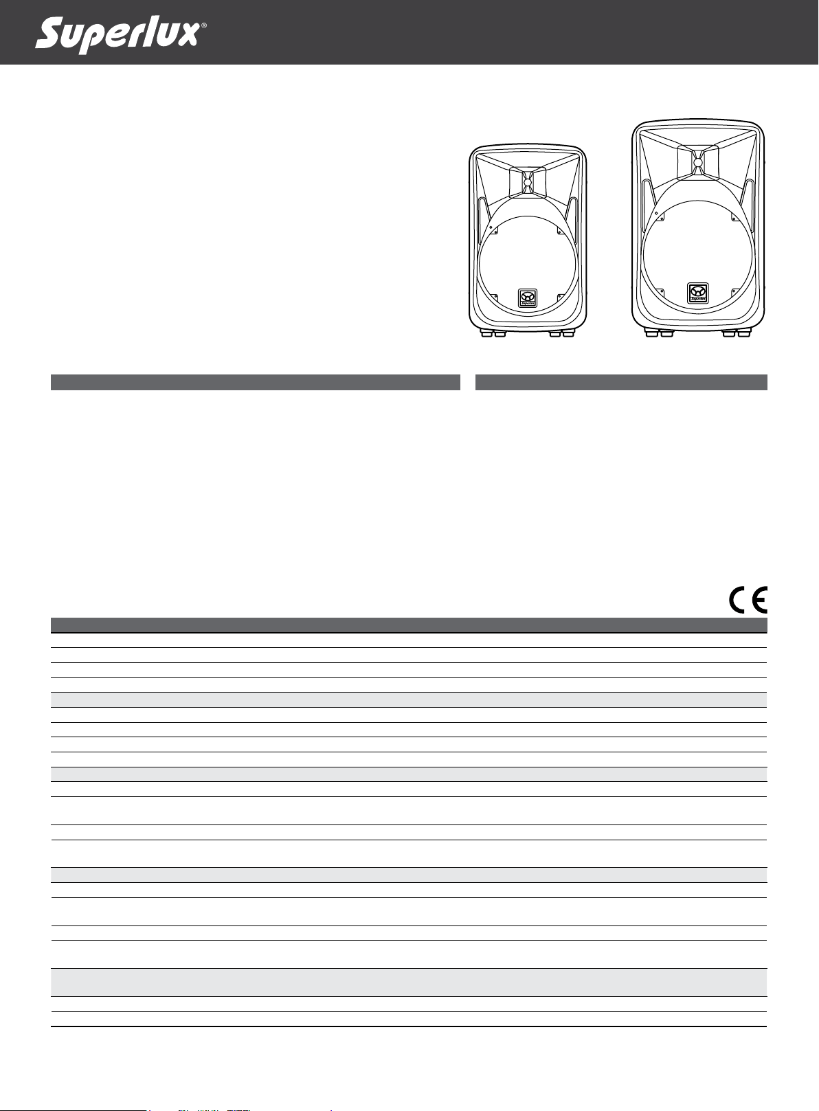
12” 2-way Active Sound Reinforcement Loudspeaker
15” 2-way Active Sound Reinforcement Loudspeaker
Live Sound, Speech, Playback, DJ, A/V, Institutional Venues
General Description
The SF112A and SF115A are 2-way powerful and reliable loudspeakers. With
its high-current capacity ampliers, high-output 1.75” titanium diaphragm
compression driver, and special magnet heat radiator woofer, they produce an
even smoother sound than the original. Our design goal was to build a sound
reinforcement speaker with:
• High output, most reliable and accurate playback.
• Very wide, smooth dispersion of mid and high frequencies.
• Light weight and ergonomical design for easy transport.
Through the combined resources of our analog engineers, and our experienced
transducer engineers, and the the result is a highly impact sound reinforcement
system which will amaze your hearing experience.
SF112A SF115A
Features
• 2-way bi-amplied, Active loudspeaker system
• 300W class-D, LF amp / 100W HF amp
• High-output precision titanium compression driver
• Neodymium long-throw low frequency transducer
• Built-in 24dB LR electronic crossover
• Mic/line input and pass-thru connector
• Lightweight molded composite cabinet
• 45 or 55 degree angles for aiming up toward
performers when used as a oor monitor
• Flyable, pole mountable, oor wedge-able ,
stackable, and wall mountable
• Optional active subwoofer SF118AS to extend very
low frequency response
Specications
Model No. SF112 A SF115 A
Type 12" 2-way 15" 2-way
LF Power Amp 300W (class D), RMS 300W (class D), RMS
HF Power Amp 100W (class AB), RMS 100W (class AB), RMS
Input Type servo balanced servo balanced
Imput Impedance 20 kΩ 20 kΩ
Sensitivity Line: 1.23V (+4dBu) Line: 1.23V (+4dBu)
Freq. Range (-10dB) 50 Hz - 15k Hz 45 Hz - 15k Hz
Max Calculated SPL 128 dB 129 dB
Crossover Frequency 2.4 k Hz 2.4k Hz
HPF Switchable 100 Hz Switchable 100 Hz
Connectors Input: XLR
AC Input Male IEC Male IEC
AC Power Requirement
(Depends on region)
HF Horn Coverage, Angles(-6dB) 90°H x 45°V 90°H x 45°V
Enclosure Material (PP) Polypropylene (PP) Polypropylene
Suspension 5 × M8:
Finish/Color Black Black
Transducers/ Replacement Parts LF: L12FN 12” (305mm), Neodymium
Dimensions(HxWxD) 62.3 × 37.8 × 36.3 (cm)
Net Weight 19.5 kg (43 lbs) 22 kg (48.5 lbs)
Shipping Weight 21.8 kg (48 lbs) 24.5 kg (54 lbs)
Output: Male XLR Link
115V, 50 Hz/60 Hz
230V, 50 Hz/60 Hz
Top×2, Bottom × 2 and 1 on rear of enclosure
HF: H44F, 1.75” (44 mm), Ferrite
24.5 × 14.9 × 14.3 (in.)
Input: XLR
Output: Male XLR Link
115V, 50 Hz/60 Hz
230V, 50 Hz/60 Hz
5 × M8:
Top×2, Bottom × 2 and 1 on rear of enclosure
L15FN 15” (381 mm), Neodymium
HF: H44F, 1.75” (44 mm), Ferrite
70 × 47 × 41 (cm)
27.6 × 18.5 × 16.1 (in.)
MADE IN CHINA
Page 2
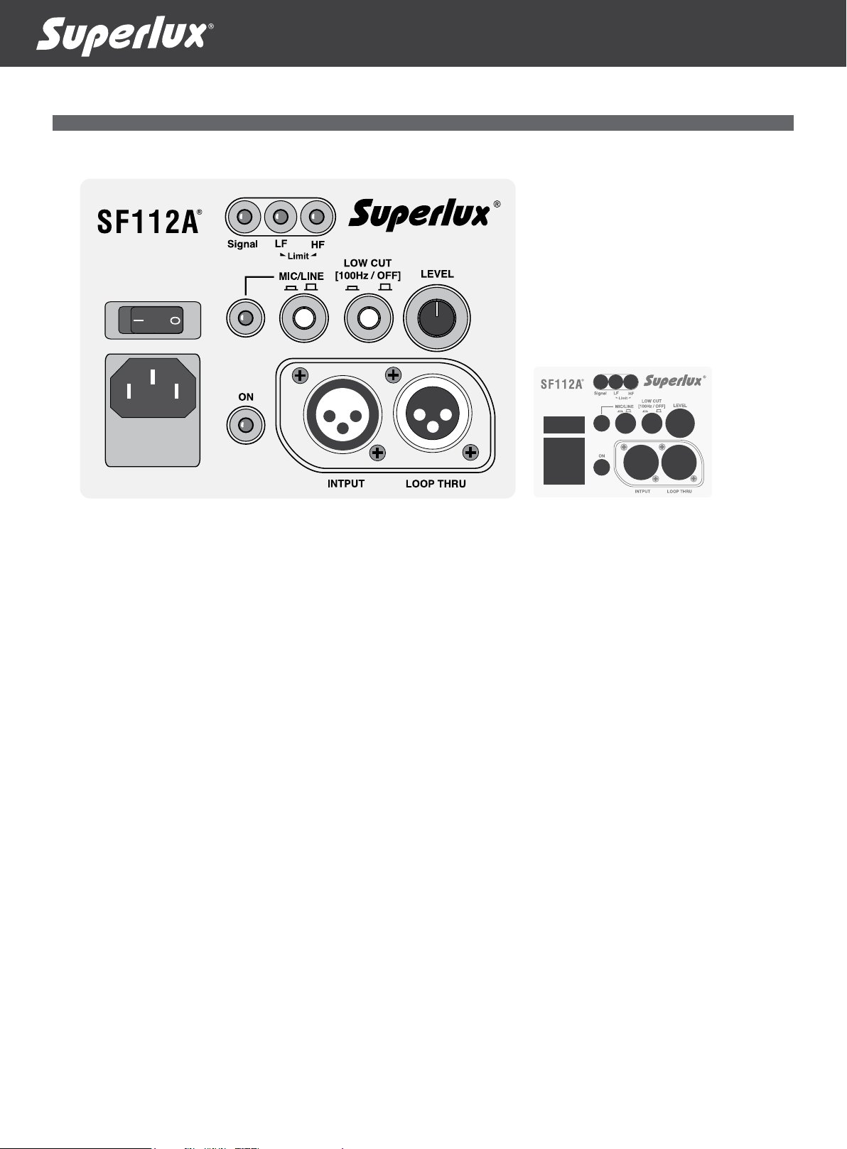
Rear Panel of SF112A and SF115A
8 9 10
1. IEC POWER SOCKET
Before connecting to the AC outlet, make sure the voltage is
same as required.
2. POWER SWITCH
This switch will determine the SF Series speaker where on or
off. Make sure the level control is down before you turn it on.
3. ON indicator
This green indicator lights on when power is turned on and it
goes off when power is off.
4. MIC/LINE level control
This knob determines the input level (microphone or line
inputs) to be sent to built-in power amplier.
5. LOW CUT FILTER
This Pushing in this switch engages a low-cut lter, which
rolls off 12 dB per octave at the low frequencies below 100
Hz. This is useful for minimizing stage noise (rumble) and
microphone handling noise. It is highly recommended that
you engage this switch when using the SF speaker as a stage
monitor. This allows the bass amplier to utilize its power for
those frequencies useful in stage monitor applications.
6. MIC/LINE SWITCH
Press down this button and the INPUT jack is for microphone
input source, and release this button the INPUT jack is for
line source, like mixer or signal processors.
2
1
3
4567
11 12
8. SIGNAL INDICATOR
When input level gets to -40dBu, then this indicator will be on
to inform the user there is input signal sent in.
9. LF LIMITER
When built-in LF power amplier is overloaded, the builtin limiter circuit will be engaged to the audio path to prevent
speaker damaged by over-drive or excess signal level. This
indicator will keep on when LF limiter is triggered.
10. HF LIMITER
When built-in HF power amplier is overloaded, the builtin limiter circuit will be engaged to the audio path to prevent
speaker damaged by over-drive or excess signal level. This
indicator will keep on when HF limiter is triggered.
11. XLR INPUT JACK
This is a female XLR-type connector that accepts a
balancedor unbalanced mic- or line-level signal.
12. XLR LOOP THRU JACK
This is a male XLR-type connector that produces exactly the
same signal that is connected to the INPUT jack. It can be
a balanced or unbalanced mic- or line-level signal. Use it to
daisy-chain several active speakers together off the same
signal source.
7. MIC/LINE INDICATOR
When MIC/LINE SWITCH (no. 6) is pressed down, this
indicator will be lighted up, and the VOLUME CONTROL
(no. 4) is for microphone input. When it is off, then VOLUME
CONTROL (no. 4) is for line source.
Page 3

Dimensions
Frequency Response
37.8 mm
(14.9 in.)
36.3 mm
(14.3 in.)
62.3 mm
(24.5 in.)
SF 112 A
Block Diagram of SF112A and SF115A
Performance Match
47 mm
(18.5 in.)
SF 115 A
41 mm
(16.1 in.)
70 mm
(27.6 in.)
Optional Accessories
SF 112 A
SF 115 A
Optional SF118AS 18" active subwoofer with 500 watts
class-D power amp to extend low end frequency response
and SPA01 subwoofer pole allows to put SF112A or SF115A
on the top of subwoofer.
Installation & Placement of SF112A and SF115A
Suspension
On a Wall
Tripod Stand
model# SPS410B
U-Bracket Kit
model# AX112 and AX115
AX112 for SF112A
SP S 410 B
On a Stand For Monitor
Stacking
Pol Mount on a
Subwoofer
AX115 for SF115A
Contact
Marketing and sales
Superlux Taiwan
+886-2-26931323
sales@superlux.com.tw
support@superlux.com.tw
www.superlux.com.tw
Manufacturing & logistics
Superlux Enterprise
Development(Shanghai)Co., Ltd.
LB100SF112A00 2011 NOV
Page 4

SF112A
SF115A
12吋兩音路有源擴聲音箱
15吋兩音路有源擴聲音箱
現場演出、演講、音樂播放、DJ、音響/視訊、機構演出場地
SF112A SF115A
概述
SF112A 和 SF115A是强悍有力且坚固耐用的音箱。具有高电流功率扩大机、高音压1.75
吋
钛金属振 膜压缩驱动单元及特殊磁铁 热幅射低音单元,所以能产生比一般喇叭更
平顺的音色。而我们的设计的SF系列喇叭的目标是要建立PA扩声喇叭含有以下特色:
•
高 输 出 、最 耐 用 且 音 色 精 准
•
很 宽 、顺 畅 的 中 、高 音 扩 散 角 度
•
轻量及符合人体工学,使之易于携行
经由我们资深的线路工程师及单体工程师团队的努力,使得以上每一个特点均能具体
实现。而S F系列的的结果就是充满动态能量的扩音喇叭,它的音色将给你惊讶的听觉
体验。
規格
型號 SF112A SF115A
型式 12吋兩音路 15吋兩音路
低頻功放 300W, RMS (平均功率)@1% THD 300W, RMS (平均功率)@1% THD
高頻功放 100W (AB), RMS (平均功率)@1%THD 100W (AB), RMS (平均功率)@1%THD
輸入型式 伺服平衡式 伺服平衡式
輸入阻抗 20 kΩ 20 kΩ
靈敏度 1.23V (+4 dBu) 1.23V (+4 dBu)
頻率響應(-10dB) 50 Hz - 15k Hz 45 Hz - 15k Hz
最大聲壓 128 dB 129 dB
分頻點 2.4 k Hz 2.4k Hz
高通濾波器 可切換 100 Hz 可切換 100 Hz
接口 輸入: XLR 母座
電源插座 Male IEC Male IEC
電源需求(依區域而定) 115V, 50 Hz/60 Hz
高頻號角涵蓋角(-6dB) 水平×垂直 90°H ×45°V 水平×垂直 90°H ×45°V
箱體材質 聚丙烯 (PP) 聚丙烯 (PP)
懸吊點 5個M8 (頂部×2、底部×2、背面×1) 5個M8 (頂部×2、底部×2、背面×1)
表面顏色 黑色 黑色
單元/更換零件 低頻: L12FN 12"(305 mm), 釹鐵
尺寸(高×寬×深) 62.3 x 37.8 x 36.3 (cm)
淨重 19.5 kg (43 lbs) 22 kg (48.51 lbs)
毛重 21.8 kg (48 lbs) 24.5 kg (54 lbs)
輸出: XLR 公座
230V, 50 Hz/60 Hz
高頻: H44F, 1.75" (44 mm), 鐵氧體
24.5 x 14.9 x 14.3 (in.)
特徵
•
双功放及优化有源音箱系统
•
30 0瓦D类低音功放 及10 0瓦高音功放
•
高音压输出之精准钛金属压缩式驱动
•
高能量钕铁长冲程低音单元
•
内建6阶/24d B主动分频器
•
麦克风/高电平输入及直接输出接口(XLR)
•
轻量化的塑料结构提供最佳的移动便利
•
45度及55度之反馈监听音箱角度
•
可悬吊、音箱架安装、墙面安装、反馈监听音箱及堆栈
輸入: XLR 母座
輸出: XLR 公座
115V, 50 Hz/60 Hz
230V, 50 Hz/60 Hz
低頻: L15FN 15" (381 mm), 釹鐵
高頻: H44F, 1.75" (44 mm), 鐵氧體
70 x 47 x 41 (cm)
27.6 x 18.5 x 16.1 (in.)
MADE IN CHINA
Page 5

SF112A及SF115A背板功能圖
8 9 10
1. 电源插座
在插入电源前,请先确定所提供的电源电压与喇叭所设定
需求的电压是一致的。
2. POWER电源开关
此开关可设定接通或关掉电源。在打开或关掉电源前,请
先确定音量旋钮是设定在最小的位置。
3. ON 电源指示灯
当电源打开时,此指示灯将点亮。
4. MIC/LINE LEVEL音量控制
此旋钮决定接至此喇叭之麦克风或高电平讯号的音量大
小,讯号将传送至内建的功率放大器。
5. LOW CUT FILTER 高通滤波器
按下此开关将接上高通滤波器,每倍频衰减12分贝,频率
点定在100赫兹。它的用处是在减少从舞台震动传来的噪音
或是减少麦克风的手持噪音。当SF喇叭是用来当作舞台监
听喇叭使用时,强烈建议将此按键按下,以降低回授产生
的可能性。
6. MIC/LINE 麦克风/高电平讯号选择开关
按下此键,适合用于输入讯号为麦克风讯号; 释放此键,适
合来自于混音机或讯号处 理器的高电平讯号。
2
1
3
4567
11 12
7. MIC/LINE 麦克风/高电平指示灯
当编号6的MIC/LINE键被按下时,此灯点亮,表示目前编号
4的音量旋钮适用于麦克风输入讯号; 该键释放时,此灯熄
灭,表示目前编号4的音量旋钮适用于高电平输入讯号。
8. SIGNAL 讯号指示灯
当有讯号 输入 至 S F 喇叭达到-40d B u 时,此灯号即点亮。
9. LF LIMITER 低频扩大机限幅器
当输入讯号过大,造成内建扩大机过载时,会启动限幅器。
此灯号显示低频扩大机巳启动限幅器保护线路。
10. HF LIMITER 高频扩大机限幅器
当输入讯号过大,造成内建扩大机过载时,会启动限幅器。
此灯号显示高频扩大机巳启动限幅器保护线路。
11. XLR INPUT 输入插座
此XLR母座允许由调音台或是讯号处理器传送过来的高电
平讯号的 插入。麦克风讯号 也 允许由此接 入。
12. XLR LOOP THRU连接输出插座
可透此接座连接至另一支SF喇叭的输入插座中,形成一个
系列的连接,扩充喇叭的音量及涵盖面积。
Page 6

尺寸
頻率響應圖
37.8 mm
(14.9 in.)
SF 112 A
36.3 mm
(14.3 in.)
62.3 mm
(24.5 in.)
47 mm
(18.5 in.)
SF 115 A
41 mm
(16.1 in.)
70 mm
(27.6 in.)
SF112A及SF115A系統方塊圖
搭配超低音 選購配件
SF 112 A
SF 115 A
可选购18吋有源500瓦低类功放超低音箱,以扩展低频的表
现。再加上一支SPA01超低音音箱立杆,可将SF112A或SF115A
架在超低音音箱上。
SF112A及SF115A位置和安裝
懸吊 腳架上 主音箱+
堆棧 反饋音箱牆上
SP S 410 B
U型安裝吊架音箱立架
AX112 for SF112A
AX115 for SF115A
超低音音箱
連絡我們
中国地区营销和业务
旭广企业发展(上海)有限公司
021-69223756
shsales@superlux.com.tw
support_cn@superlux.com.tw
www.superlux.com.tw
国际营销和业务
Supe rlux 舒伯乐 台湾
+886 -2-26931323
sales@superlux.com.tw
LB100SF112A00 2011 NOV
 Loading...