

Page 1

USER MANUAL
BroadLighter-M Series
Broadband Superluminescent Diode
Benchtop Light Source
Superlum, Unit B3, Fota Point Enterprise Park, Carrigtwohill, Co. Cork, Ireland.
Phone: +353 21 4533666, fax: +353 21 4533026, e-mail: sales@superlum.ie
www.superlumdiodes.com
Superlum reserves the right to change or make corrections to this manual further without notice.
Revision 16
June 2015
Page 2

Page 3

Declaration of Conformity
According to ISO/IEC Guide 22 and CEN/CENELEC EN 45014
Manufacturer’s Name: Superlum Diodes Ltd.
Manufacturer’s Address: Unit B3, Fota Point Enterprise Park
Carrigtwohill, Co Cork
Ireland
Declares that,
Product Name: Broadband Superluminescent Diode Benchtop Light
Source
Product Number: BroadLighter-M
Product Options: This declaration covers all options of the above
product(s).
This product complies with the following standards/ requirements:
EMC
Standard
Limit
IEC 61326-1:1997+A1:1998 / EN
61326-1:1997+A1:1998
Group 1 Class A
CISPR 11:1990 / EN 55011:1991
4kV CD, 8kV AD
IEC 61000-4-2:1995+A1:1998 /
EN 61000-4-2:1995
3 V/m, 80-1000
MHz
IEC 61000-4-3:1995 / EN 610004-3:1995
0.5kV signal lines,
1kV power lines
IEC 61000-4-4:1995 / EN 610004-4:1995
0.5 kV line-line, 1
kV line-ground
3V, 0.15-80 MHz
IEC 61000-4-5:1995 / EN 610004-5:1995
0.5 kV line-line, 1
kV line-ground
IEC 61000-4-6:1996 / EN 610004-6:1996
Dips: 30% 10ms;
60% 100ms
IEC 61000-4-11:1994 / EN
61000-4-11:1994
Interrupt >
95%@5000ms
The product was tested in a
typical configuration
Safety
IEC 61010-1:1990+A1:1992+A2:1995 /
N 61010-1:1993+A2:1995
Laser
Safety
IEC 60825-1:2014
Page 4

BroadLighter-M Series
User Manual
Revision 16
1
Certificate Exclusions
This Declaration, and all documentation, and all
equipment cited herein, shall cease to conform to and/or
be compliant with the above Directives, Standards and
Specifications unless the following conditions are
complied with and applied by the Purchaser /User:
This Product shall be installed, used and
maintained as directed by Superlum.
The Product shall not be modified and/or changed
without prior written approval of Superlum.
Although every effort is made by Superlum to comply with
the above Directives and Standards, it is the responsibility
of the Purchaser and/or User of the equipment to ensure
that all claims and assurances with regards to such
directives and Standards are complete, correct and
satisfied.
IEC 825-1
Page 5

Warranty
2
Warranty
Warranty
Superlum warrants the BroadLighter-M Broadband SLD
Benchtop Light Source for a period of 12 months from the
date of shipment. During this warranty period Superlum
will repair / exchange any unit proven to be defective.
Repairs are warranted for the balance of the original
warranty period or at least 90 days.
For warranty repairs or service the unit must be
returned to Superlum at the customer’s expense.
Limitation of Warranty
Superlum will not accept liability for any incidental
damage caused by the failure of this product. This
warranty does NOT cover:
Any defect/damage caused by improper
operation.
Accompanying accessories, e.g. fiber optical
patchcables, AC power cords, etc.
Dismantling any part of the unit without prior approval
from Superlum will void the warranty.
Page 6

BroadLighter-M Series
User Manual
Revision 16
3
Statement of Calibration
Superlum certifies that this product has been inspected,
tested, and calibrated to meet its published specifications.
Page 7

TABLE OF CONTENTS
4
TABLE OF CONTENTS
Warranty ...................................................................... 2
TABLE OF CONTENTS ............................................... 4
Safety Symbols and Terms ........................................ 7
General Safety Information ........................................ 9
Acronyms and Abbreviations .................................. 20
1. General Information .............................................. 22
1.In This Manual …………………………………………………………….22
1.2 Instrument Description ................................................. 25
1.3 Product Specifications ................................................. 32
2. Installation ............................................................. 35
2.1 Unpacking and Initial Inspection................................. 35
2.1.1 Unpacking the Instrument ................................ 35
2.1.2 Initial Inspection ................................................. 36
2.2 Preparation for Use ...................................................... 38
3. Local Mode of Operation ...................................... 40
3.1 Front-Panel Features ................................................... 40
Page 8

BroadLighter-M Series
User Manual
Revision 16
5
3.2 Rear-Panel Features .................................................... 42
3.3 Operating Instructions .................................................. 44
3.4 Power OFF Instructions ............................................... 47
3.5 Interface Menu .............................................................. 48
3.5.1 Main Interface Screen....................................... 48
3.5.2 Main Screen Status Messages ....................... 52
3.5.3 Main Screen Status Indicators ........................ 53
3.5.4 Main Menu .......................................................... 54
4. Remote Mode of Operation .................................. 57
4.1 Remote Control Interface ............................................ 58
4.2 USB interface… ............................................................ 60
4.2.1 System Commands ........................................... 62
4.2.2 USB Mode Commands ..................................... 64
4.3 Superlum Companion Software ................................. 77
4.3.1 Minimum System Requirements .................... 78
4.3.2 Installing the USB drivers ................................ 79
4.3.3 Installing Companion Software ...................... 80
Page 9

6
4.3.4 User Interface .................................................... 81
4.3.5 Self Test Procedure .......................................... 84
4.3.6 Uninstalling the Program .................................. 86
5. Cleaning Instructions ........................................... 87
5.1 Safety Precautions ....................................................... 87
5.2 Cleaning………………………………………………………….………….89
6. Service and Support ............................................ 92
6.1 Returning the Instrument for Servicing ...................... 92
6.2 Preparing the Instrument for Shipment ..................... 93
6.3 Instrument Disposal ...................................................... 95
Page 10

BroadLighter-M Series
User Manual
Revision 16
7
Safety Symbols and Terms
This section deals with information on the safety symbols
and terms which are used on the instrument or in the
manual, and gives explanations about what they stand
for. These symbols and terms indicate precautions you
must strictly follow to safely operate the instrument.
Before you begin using your BroadLighter-M,
please read the following explanations:
The WARNING sign denotes a hazard. It
calls attention to a procedure, practice,
or the like, which, if not correctly
performed or adhered to, could result in
personal injury. Do not proceed beyond
a WARNING sign until the indicated
conditions are fully understood and
met.
The CAUTION sign denotes a hazard. It
calls attention to an operating procedure,
or the like, which, if not correctly performed
or adhered to, could result in damage to or
destruction of the entire product or part
thereof. Do not proceed beyond a
CAUTION sign until the indicated
conditions are fully understood and met.
WARNING
CAUTION
Page 11
Safety Symbols and Terms
8
The NOTE sign denotes important
information. It calls attention to
procedures, practice, condition, or the like,
which is essential to highlight.
The CE mark shows that the product
complies with all relevant European Legal
Directives.
The warning label denotes visible and/or
invisible laser radiation.
This label means the compliance with the
requirement of COMPLIANT the RoHS
Directive (Directive 2002/95/EC).
NOTE
Page 12

BroadLighter-M Series
User Manual
Revision 16
9
General Safety Information
High voltage inside. To avoid
electrical shock, before powering
unit, make sure that the protective
conductor of the 3-conductor power
cord is correctly connected to the
protective earth contact of the socket
outlet. Improper grounding can
cause electric shock resulting in
severe injury or even death. Do not
operate without cover installed.
This unit must not be operated in an
explosive environment.
The general safety precautions must be observed during all
phases of operation, service, and repair of the instrument.
Failure to comply with these precautions or with specific
warnings elsewhere in this manual violates safety standards of
design, manufacture, and intended use of the instrument.
Superlum assumes no liability for the customer failure to comply
with these requirements.
Before Applying Power, verify that the product is set to match
the available line voltage.
WARNING
Page 13
General Safety Information
10
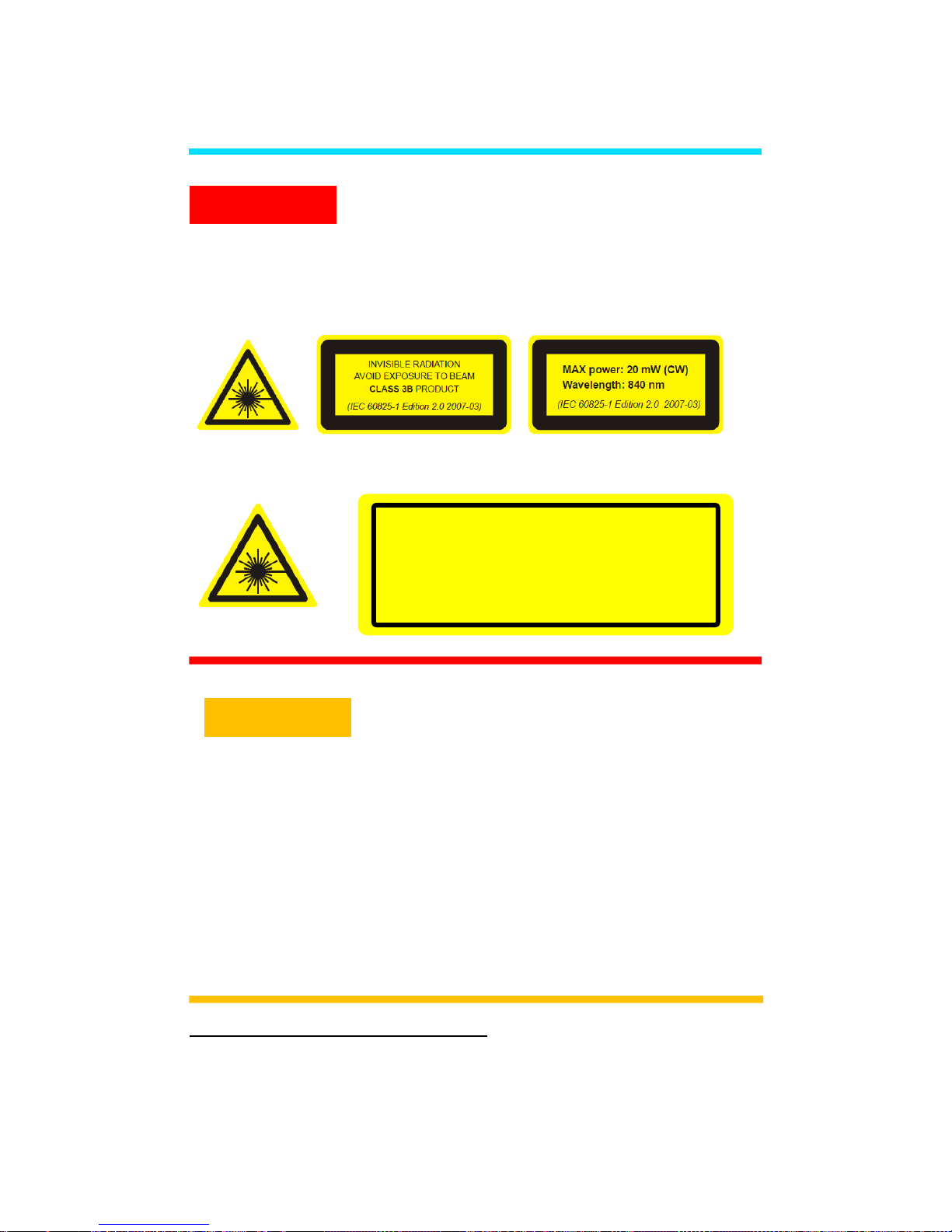
Avoid Exposure – Laser Radiation emitted from
optical aperture. BroadLighter-M contains one of
the following sets of Laser Safety Information
Labels
1
.
Set 1:
Set 2:
Depending on the configuration of the
BroadLighter-M, the instrument can be assigned
to Class 1, Class 3R or Class 3B laser product in
accordance with IEC 60825-1:2014. Refer to Laser
Safety label placed on the top panel and read the
safety information related to the safety class of
your instrument. Use of controls or adjustments
or performance of procedures other than those
specified herein may result in hazardous
radiation exposure.
1
The labels shown are the examples and for reference only. The actual labels and their position
may differ.
WARNING
CAUTION
WARNING – CLASS 3B INVISIBLE LASER RADIATION
AVOID EXPOSURE TO BEAM CLASS 3B LASER
PRODUCT
Wavelength: 750-1100 nm
CW/Pulsed: CW
Max Average Power: < 50 mW
Complies with IEC/EN 60825-1:(2014)
Page 14

BroadLighter-M Series
User Manual
Revision 16
11
Output Aperture for BroadLighter-M is a
single mode optical fiber with
numerical aperture2 (NA) = 0.14.
Laser Safety Labeling
Depending on configuration, BroadLighter-M can be attributed
to different classes of Laser Safety according to IEC 608251:2014. The interior of BroadLighter-M contains Laser Safety
labels. Laser safety information label is located on the lid of the
instrument. Laser aperture label is located next to FC/APC
connector on the front panel of an instrument. Laser Hazard
label is located on the lid of an instrument.
CLASS 1 Laser Product
Light sources assigned to Class 1 are safe during the use,
including the long-term direct intrabeam viewing, even if the
exposure with optical viewing instruments (e.g. eye loupes or
binoculars) occurs. Extra care must be taken to the following:
Using controls, adjustments, or operating procedures that are
different from those specified in this manual may result in
radiation exposure hazardous to the user.
When the instrument is used with certain optical elements—
such as optical amplifiers, lenses, collimators, and the like—
which are not supplied with the product as original accessories,
or the product is integrated into a high-level system, it is strictly
2
Parameter may vary for a custom version of BroadLighter-M
NOTE
Page 15

General Safety Information
12
recommended to reclassify the final optical system in order to
determine its total degree of optical radiation hazard. The
reason for this is that the Class may increase under these
conditions. It is the responsibility of a person (or organization)
who performs such integration to provide correct
reclassification for the optical system at the final stage.
It must be noted that it is the user who is responsible for being
aware of possible risk associated with using Class 1 laser
products as well as being adequately trained for working with
such light sources. Superlum is not liable for any personal
injury, property damage, or other (direct or indirect) damage of
any nature caused by personal faults, improper and/or
inadequate using of the instrument coming from disregarding
the necessary aspects of laser safety.
According to IEC 60825-1, this product
has been classified for an exposure
duration of up to 100 ms. For other
practical applications in which the
exposure duration is greater than 100
ms, the product must be reclassified.
CLASS 3R Laser Product
Light sources assigned to Class 3R emit optical radiation that
can exceed the MPE (Maximum Permissible Exposure) under
NOTE
Page 16

BroadLighter-M Series
User Manual
Revision 16
13
the direct intrabeam viewing, but in most cases the risk of injury
is relatively small because the AEL (Accessible Emission Limit)
for Class 3R is only 5 times greater than the AEL for Class 1,
which is safe for the user. The risk of injury rises as the
exposure duration increases. The exposure will be safe for the
user unless it is a deliberate ocular exposure.
The risk of injury is actually minimized due to the following facts:
Unintentional exposures would rarely reflect worst-
case conditions, for example, of beam alignment with
the pupil or worst-case accommodation.
The inherent safety margin in the MPE.
Natural aversion behavior for exposure to bright light
for the case of visible radiation and by the response to
heating of the cornea for far infrared radiation.
The direct intrabeam viewing is supposed to be unlikely for
possible practical applications of this instrument. Otherwise, the
user should reclassify the instrument. If you are unsure about
providing the correct reclassification, contact Superlum on this
issue.
Using controls, adjustments or operating procedures that are
different from those specified in this manual may result in
radiation exposure hazardous to the user. When the instrument
is used with certain optical elements, such as optical amplifiers,
lenses, collimators, etc., which are not supplied with the product
as original accessories, or the product is integrated into a high-
Page 17

General Safety Information
14
level system, it is strictly recommended to reclassify the final
optical system. The reason for this is that the Class may
increase under these conditions. It is the responsibility of an
end-user who performs such integration to provide correct
reclassification for the optical system at the final stage. It must
be noted that it is the user who is responsible for being aware
of possible risk associated with using Class 3R laser products
as well as being adequately trained for working with such lighter
sources. Superlum is not liable for any personal injury, property
damage, or other (direct or indirect) damage of any nature
caused by personal faults, improper and/or inadequate using of
the instrument coming from disregarding the necessary aspects
of laser safety. These features are as follows:
Key-operated master control
Remote interlock connector
Illuminated indicator on the pushbutton for the output
emission activation
Audible and visible warning signals for the output
emission activation
Protective metal cap for the optical output
Laser safety labeling
This manual contains the most comprehensive information on
the laser safety controls (and measures) built into the
instrument.
Page 18

BroadLighter-M Series
User Manual
Revision 16
15
According to IEC 60825-1, this product
has been classified for an exposure
duration of up to 100 ms. The product
must be reclassified for practical
applications in which the exposure
duration is greater than 100 ms.
CLASS 3B Laser Product
Light sources assigned to Class 3B are always hazardous for
the intra beam ocular viewing even if an accidental short-time
exposure occurs. Viewing them through optical elements with
diffuse-reflecting properties is usually safe for the user. Pay
close attention to the following information: Using controls,
adjustments, or operating procedures that are different from
those specified in this manual may result in radiation exposure
hazardous to the user.
When the instrument is used with certain optical elements such
as optical amplifiers, lenses, collimators, etc., which are not
supplied with the product as the original accessories, or the
product is integrated into a high-level system, it is strictly
recommended to reclassify the final optical system in order to
determine its total degree of optical radiation hazard.. It is the
responsibility of an end user who performs such integration to
provide correct reclassification for the optical system. It must be
noted that it is the end-user who is responsible for being aware
NOTE
Page 19

General Safety Information
16
of possible risk associated with using Class 3B laser products
as well as being adequately trained or working with such lighter
sources. Superlum is not liable for any personal injury, property
damage, or other (direct or indirect) damage of any nature
caused by personal faults, improper and/or inadequate using of
the instrument coming from disregarding the necessary aspects
of laser safety. Incorporated into BroadLighter-M are the
following laser safety features:
Key-operated master control
Remote interlock connector
Illuminated indicator on the pushbutton for the output
emission activation
Audible and visible warning signals for the output
emission activation
Protective metal cap for the optical output
Laser safety labeling
This manual contains the most comprehensive information on
the laser safety controls (and measures) built into the
instrument. Please read thoroughly this manual to acquaint
yourself with all features and functions for laser safety before
you start working with the BroadLighter-M.
Page 20

BroadLighter-M Series
User Manual
Revision 16
17
According to IEC 60825-1, this product
has been classified for an exposure
duration of up to 100 ms. The product
must be reclassified for practical
applications in which the exposure
duration is greater than 100 ms.
NOTE
Page 21

General Safety Information
18
Safety Earth Ground
To minimize shock hazard, the instrument chassis and cabinet
must be connected to an electrical ground. The instrument must
be connected to the AC power line through a three-conductor
power cable, with the third wire firmly connected to an electrical
ground (safety ground) at the power outlet. Any interruption of
the protective (grounding) conductor or disconnection of the
protective earth terminal will cause a potential shock hazard
that could result in personal injury.
DO NOT operate the instrument in an explosive
atmosphere or in the presence of flammable
gases or fumes.
DO NOT perform procedures involving cover or
shield removal unless you are qualified to do
so. Operating personnel must not remove
equipment covers or shields. Procedures
involving the removal of covers and shields are
to be performed by service-trained personnel
only.
DO NOT operate damaged equipment.
Whenever it is possible that the safety
protection features built into this product have
been impaired, either through physical
Page 22

BroadLighter-M Series
User Manual
Revision 16
19
damage, excessive moisture or any other
reason, remove power and do not use the
product. Return the product to Superlum to
ensure the safety features are operational.
DO NOT substitute parts or modify equipment.
Because of the danger of introducing additional
hazards, do not install substitute parts or
perform any unauthorized modification to the
product. Return the product to Superlum for
service and repair.
Page 23

Acronyms and Abbreviations
20
Acronyms and Abbreviations
The necessary information on acronyms and abbreviations is
summarized in the following table:
TABLE A. Acronyms and Abbreviations Used
Abbreviation
Definition
O
C
Degree Celsius
mW
Milliwatt
nm
Nanometre
dB
Decibel
AC
Alternating Current
AEL
Accessible Emission Limit
APC
Automatic Power Control
BLS
Broadband Light Source
CW
Continuous Wave
DC
Direct Current
LED
Light Emitting Diode
MPE
Maximum Permissible Emission
NA
Numerical Aperture
PC
Personal Computer
SLD
Superluminescent Diode
TEC Thermoelectric Cooler
Page 24

BroadLighter-M Series
User Manual
Revision 16
21
If you see a term for which the definition
is not given here, refer to special
reference books for the necessary
explanations or consult with Superlum
on this issue.
NOTE
Page 25

1. General Information
22
1. General Information
This chapter contains general information concerning the
BroadLighter-M Broadband SLD Benchtop Light Source.
Included in this chapter are a description of the instrument, an
outline of this manual, general specifications, information on the
Laser Class to which your BroadLighter-M is assigned, and a
description of the laser safety measures employed in this
equipment.
1.1 In This Manual
This manual contains the most comprehensive information
required to install, operate, and clean your Superlum
BroadLighter-M Broadband SLD Benchtop Light Source.
The goal of this section is to give a short overview of the
chapters and sections comprising this document. Knowing the
layout of the manual helps you find answers to the vast majority
of questions you may have about installing, using,
programming, cleaning, and servicing your BroadLighter-M.
The manual consists of six chapters. Detailed information about
the principles of operation, installing, and using the
BroadLighter-M is provided in four chapters which are placed at
the beginning of the manual. At the end of the document there
are two chapters containing additional information (i.e. detailed
Page 26

BroadLighter-M Series
User Manual
Revision 16
23
instructions) about cleaning and obtaining service. Use the
manual as a reference book when you are installing and
operating with the instrument.
Please, carefully read this manual before using your
BroadLighter-M. You should pay attention to the warnings and
cautions presented in this manual. If necessary, refer to section
"Safety Symbols and Terms" for definitions of these terms. If,
after reading this manual, some of the explanations remain
unclear to you or you need extra information on a particular
issue, do not hesitate to contact Superlum for more details or
additional explanations.
The chapters in this manual are set out as follows:
Chapter 1, "General Information", begins with outlining
the scope of this manual. After that, you will find background
information concerning the BroadLighter design and the
principles of operation. Following this are technical
specifications on the product and laser safety information,
which are provided in the corresponding sections of the
chapter.
Chapter 2, "Installation", takes you through unpacking
and inspection procedures and explains how to prepare the
BroadLighter-M for use.
Page 27

1. General Information
24
Chapter 3, "Local Mode of Operation", introduces frontand rear-panel features and provides detailed operating
instructions to demonstrate how to use the BroadLighter-M.
Chapter 4, "Remote Mode of Operation", explains how to
control the instrument remotely via a PC. It provides a full
description of each command and query supported by the
instrument and the most comprehensive information on the
Superlum BroadLighter-M Companion Software, which comes
with the instrument.
Chapter 5, "Cleaning Instructions", deals with a
description of the proper cleaning procedures that you should
regularly apply to both the BroadLighter-M and optical
accessories, such as optical patchcables, adapters, optical
connectors, etc.
Chapter 6, "Service and Support", explains what you
should do if you encounter a problem with the instrument. It also
gives detailed recommendations for repacking the instrument
before returning it to Superlum for servicing.
Page 28

BroadLighter-M Series
User Manual
Revision 16
25
1.2 Instrument Description
For a number of optical applications, such as optical coherence
tomography, optical metrology, characterization of optical
components etc., broadband light sources based on the use of
SLD modules are considered to be best suited. The reason for
choosing these optical modules is related to their remarkable
performance parameters. Among all types of modules
presented on the market, the SLD modules best combine high
optical power similar to that emitted by laser diodes with
broadband optical spectra characteristics of LEDs. These
advantages of SLDs allow the user to avoid unwanted
interference effects, like speckle or ghost signals. In contrast,
narrowband light sources such as laser diodes often give rise
to such effects due to a high temporal coherence of their output
emission.
The BroadLighter-M is an advanced SLD-based
broadband light source intended for a benchtop applications.
Among other broadband light sources of this kind, it features
excellent performance parameters, easy-to-use front-panel
operation, and long-term stability of its technical characteristics,
high reliability, minimal maintenance, and many others. The
instrument can be controlled either manually by using its frontpanel controls or remotely via PC. For remote control, the
instrument is equipped with USB and REMOTE CONTROL
interface. Superlum BroadLighter-M Companion Software,
Page 29

1. General Information
26
which is supplied with the instrument, has a user-friendly
interface that permits the user to put the instrument under
remote control immediately after its installation.
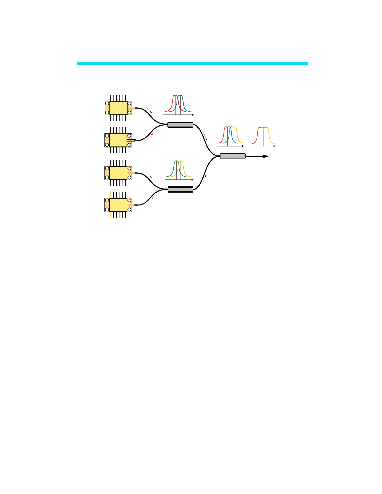
In comparison to a standalone SLD module, the
BroadLighter-M demonstrates the extended optical spectrum
with an extremely wide -3 dB bandwidth, which in turn
corresponds to very low temporal coherence. This occurs due
to combination of the optical emissions of up to four spectrally
matched SLD modules. The actual number of SLDs depends
on your instrument configuration. Figure 1.1 sketches the
principle of light combining in the BroadLighter-M. To combine
broadband emissions of the SLDs broadband fiber-optic
couplers are utilized. The couplers feature low insertion losses
and small changes in the coupling ratio for the necessary range
of wavelengths.
Page 30
BroadLighter-M Series
User Manual
Revision 16
27
Coupler 3
SLD 1
SLD 2
Coupler 1
Output
SLD 3
SLD 4
Coupler 2
Figure 1.1. Schematic of the Principle of Light Combining in the
BroadLighter-M. The actual number of SLDs depends on your
instrument configuration.
The internal structure of the BroadLighter-M has a
modular design. The instrument consists of an optical unit,
driver unit and a main unit. Optical unit has optical components
comprising the optical scheme of the instrument. It also stores
the information about the SLD operating parameters, the driver
unit has an integrated DC power supply, as well as driving
electronics and temperature control for SLDs. The main unit
acts as a motherboard for optical and driver units. This design
principle provides the possibility for a flexible exchange of unit
and the ability to adapt and upgrade the instrument to a
particular customer application.
Page 31

1. General Information
28
Superlum SLD modules used in the BroadLighter-M are
fiber-coupled optical modules with a built-in thermoelectric
cooler (TEC) and a temperature sensor which are both
necessary for active temperature control. Superlum current-and
temperature controller is used to control the driving current and
operating temperature of an SLD module.
The instrument has a wide-range voltage power supply
suitable for the 100-240 V AC power lines. All essential
information about AC power requirements is shown on the rear
panel of the instrument. It is important to note that the
BroadLighter-M is intended for indoor use only. For more
information on environmental conditions, refer to section
"Specifications".
This equipment is intended for fiber-optic applications.
To serve this purpose, it is equipped with FC/APC fiber output.
Each BroadLighter-M is shipped with an individual optical
patchcable which is used to deliver the optical output power of
the instrument to the user measuring equipment. It is important
to note that the patchcable provided with the instrument is
specially selected to best match the optical output of the
instrument. With the patchcable attached, a low-loss
connection between the BroadLighter-M and the patchcable is
obtained. Connecting user-selected patchcables to the
BroadLighter-M output is permitted but not recommended,
Page 32

BroadLighter-M Series
User Manual
Revision 16
29
because in this case the minimum optical losses in the
instrument-to-patchcable connection can hardly be ensured.
FC/APC connectors of its ends is the crucial requirement for the
patchcable to be used. Contact Superlum first if you would like
to use other types of optical connections.
The BroadLighter-M incorporates the following safety
features required by IEC 60825-1:
Key-operated master control — located on the
front panel of the instrument, this switch provides
access to activation of the optical output. The
BroadLighter-M is inoperable when the key is
removed. Using the key-operated master control
prevents unauthorized activation of the optical
output emission.
Emission indicator — the LED integrated with
SLD emission activation ON/OFF button, lights up
green when the optical power is enabled, thereby
warning the user about the output emission. The
LED will switch to red when the SLD emergency
switch-off occurs.
Emission time delay – there is a 3 second time
delay between pressing the emission ON/OFF
button and the emission activation.
Page 33

1. General Information
30
Remote Interlock connector — this feature is
located on the rear panel of the instrument. It
allows the instrument to be connected to your local
external controls for laser safety. In order to enable
the BroadLighter-M, a short circuit must be applied
across the terminals of the Remote Interlock
connector. The instrument remains inoperable
unless the Interlock connection is made.
BroadLighter-M is shipped with a shorting device
installed in the Interlock connector. If you are not
going to use this feature then you can leave the
shorting device installed. With this device installed,
you will be able to use the instrument
independently of your local laser safety system. If
you wish to make use of the Interlock feature you
will need to acquire the appropriate connector mate
and wire it your remote Interlock switch. Next,
remove the shorting device by carefully unscrewing
it from the socket and install the connector into the
Interlock input. The BroadLighter-M interlock input
only accepts a 2.5 mm monophonic jack.
Visual and audible warning about optical
output emission — these features start to operate
when the user activates the optical output by
Page 34

BroadLighter-M Series
User Manual
Revision 16
31
pressing the ON/OFF button. Remote IF
connection can be used to transfer a warning
signal from BroadLighter-M to the external warning
system.
Optical radiation hazard labeling — the cabinet
of each BroadLighter-M contains a set of warning
labels informing the user about the Class of
radiation hazard to which the instrument is
assigned. Classification is based on the rules
specified in standard IEC 60825-1:2014 "Safety of
laser products — Part 1: Equipment classification
and requirements". Each BroadLighter-M that is
assigned to this Class of laser products carries on
the instrument's cabinet a set of warning labels with
the necessary information according to its laser
hazard.
Overshooting protection — BroadLighter-M
contains a safety circuit preventing the signal from
overshooting by shutting down the output.
Using controls, adjustments, or operating
procedures that are different from those
specified in this manual may result in
radiation exposure that is hazardous to the
user.
CAUTION
Page 35

1. General Information
32
Each BroadLighter-M is assigned to a
particular Class only if it completely meets
the requirements specified in IEC 608251:2014 for that Class. According to IEC
60825-1, Class 1, Class 3R and Class 3B
products have been classified for an
exposure duration of 100 ms, which is
estimated to be a worst-case scenario. For
other practical applications in which the
exposure duration is greater than 100 ms,
the product must be reclassified.
1.3 Product Specifications
Contained in this section are general specifications for the
BroadLighter-M which are summarized in the tables below.
Note that the information given here covers general and
mechanical specifications only. For the technical information
concerning optical characteristics for your BroadLighter, please
refer to its Acceptance Test Report or contact Superlum on this
issue.
NOTE
Page 36

BroadLighter-M Series
User Manual
Revision 16
33
TABLE 1.1 General and Mechanical Specifications
Parameter
Value or Description
General:
Power Requirements
100-240VAC, 50/60Hz
40 VA MAX
AC Power Cord Plug
IEC 320 compatible
Operating Temperature Range
+5 to +35 OC
Storage Temperature Range
-30 to +70 OC
Humidity
< 80% relative humidity, noncondensing
Warm-up Time
30 min
Mechanical:
Dimensions (WxHxL)
251×112×192 mm
Weight (max)
4 kg
Enclosure
Metal case
Applicable Optical Connector
FC/APC
USB Interface Connector
Remote Control Interface
Connector
USB 2.0 Type B
9-pin DSUB for external logic
Remote Interlock Connector
2.5 mm mono phono jack
Page 37

1. General Information
34
Included in the package is one of each of the following:
TABLE 1.3 List of Contents
Item
Qty.
BroadLighter-M Broadband SLD Light Source
1 pc.
AC Power Cord
1 pc.
Master Key
1 pc.
Remote interlock jack connector
1 pc.
Optical Patchcable
1 pc.
Quick Start Guide
1 pc.
Acceptance Test Report
1 pc.
USB Cable
1 pc.
CD-ROM with User Manual and Software
1 pc.
Optical performance parameters
including 3 dB bandwidth, central
wavelength, output power, etc., are
specified and measured for each
instrument individually. For detailed
information on this issue, refer to the
Acceptance Test Report (ATR) provided
with an instrument. Specifications are
subject to change without notice.
NOTE
Page 38

BroadLighter-M Series
User Manual
Revision 16
35
2. Installation
This chapter will guide you through the unpacking and initial
preparation required in order to set-up your BroadLighter-M.
2.1 Unpacking and Initial Inspection
2.1.1 Unpacking the Instrument
To unpack the instrument, proceed as follows:
1. Place the shipping container on a flat rigid surface.
2. Cut the adhesive tapes over the top of the carton
exterior with a sharp knife and open the top flap.
3. Remove the cushioning material around the
instrument.
4. Lift the instrument and set it aside.
5. Lift the accessories and set them aside.
After unpacking the instrument, verify the receipt of the
BroadLighter-M Broadband SLD Benchtop Light Source. Refer
to the list of contents in section "Specifications" if necessary.
Page 39

2. Installation
36
2.1.2 Initial Inspection
To perform the initial inspection, proceed as follows:
1. After unpacking the instrument, check the shipping
container and its contents thoroughly to be certain
nothing was damaged during shipment.
2. If the contents are damaged or defective, contact
Superlum immediately. Keep the shipping materials for
the carrier inspection.
After transiting or handling the container in
cold weather, it must be stored at room
temperature for about two hours before
being opened. Avoid sharp changes in
temperature that might cause water
condensation on the internal parts of the
instrument. Any amount of water
condensation can be destructive for optical
components inside the BroadLighter-M.
CAUTION
Page 40

BroadLighter-M Series
User Manual
Revision 16
37
1. The BroadLighter-M is a sophisticated
optical instrument containing delicately
aligned optical equipment;
consequently, it should be handled with
great care.
2. Retain the original container for
possible future use. If the instrument is
to be sent to Superlum for servicing and
the original container is not available,
use an equal replacement for repacking.
Refer to section "Service and Support"
for further instructions.
NOTE
Page 41

2. Installation
38
2.2 Preparation for Use
Your BroadLighter-M has been configured to operate with the
AC power supply specified on the rear panel of the instrument.
The instrument is supplied with a 3-conductor detachable
power cord which grounds the instrument cabinet when it is
connected to an appropriate receptacle. The type of possible
plugs acceptable for the AC power cord are specified in the
section titled "Specifications". Before connecting the instrument
to your AC power source, check that the power line/power
supply supports the ground terminal.
To perform preparation for use, proceed as follows:
1. Place the BroadLighter-M on a flat surface, e.g. on
a table or in a rack, close to your measurement
equipment in a location with sufficient ventilation.
Make sure that no obstructions are provided for
ventilation openings of the instrument and the
optical patchcable can be easily attached to the
instrument without strain.
2. Connect AC power cord to the rear-panel power
receptacle. Use the power cord supplied with
instrument.
3. Insert the key provided with the instrument into the
MASTER KEY lock and leave it in position "O".
4. The instrument is plugged in.
Page 42

BroadLighter-M Series
User Manual
Revision 16
39
1. Do not block cooling vents at the
rear panel of the instrument. Failure
to do so may result in device
malfunction.
2. Before applying AC power to the
BroadLighter-M, check the rearpanel label for the line voltage. If it
does not meet your power source
requirements, contact Superlum on
this issue. Failure to obey this rule
may cause permanent damage to
the instrument.
CAUTION
Page 43

3. Local Mode of Operation
40
3. Local Mode of Operation
This chapter details the front- and rear-panel features of the
BroadLighter-M and provides step-by-step instructions on how
to operate the instrument in the local operating mode.
3.1 Front-Panel Features
To feel at ease with the instrument, familiarize yourself with its
front-panel and rear-panel controls, connectors, and indicators
shown in the figures which follow. Refer to Figure 3.1 for the
illustration of the front-panel controls of the BroadLighter-M.
Figure 3.1. Front-Panel Features.
2 3 4
6
1
5
7 8
7
Page 44

BroadLighter-M Series
User Manual
Revision 16
41
1—KEY OPERATED POWER SWITCH. This is a keyoperated master control used as a laser safety measure
specified in IEC 60825-1 (Edition 2.0 2007-03). Turning the key
to position "I" allows the operator to power on the instrument
and get access to SLD emission activation. When the key is in
"O" position, the instrument is OFF and the output emission of
the instrument cannot be enabled.
2—POWER LED. This LED illuminates green when the
instrument is turned ON. When the instrument is turned OFF,
the LED goes blank. The LED illuminates RED during self-test
start running if an error is present.
3—MULTIFUNCTINOAL LCD DISPLAY. This display
provides the status information for the instrument: connection
status, SLD status, output power, etc.
4—NAVIGATION BUTTONS. They are used to
navigate through the interface on the LCD screen. LCD screen
menu is described in Section 5 of this Guide.
5—MENU BUTTON. This button is used to enter the
instrument interface menu or to select the feature.
6—ON/OFF BUTTON. This button is used to
enable/disable the instrument emission. When the emission is
activated, the button LED illuminates green.
Page 45
3. Local Mode of Operation
42
7—FC/APC OUTPUT CONNRCTOR WITH A
PROTECTIVE CAP. This socket is an optical output of the
instrument. The patchcable supplied with the instrument is
connected here. The cap is used to protect the optical output
(FC/APC adapter) from dust and dirt. Always recap the optical
output, when the instrument is not in use and has no patchcable
attached.
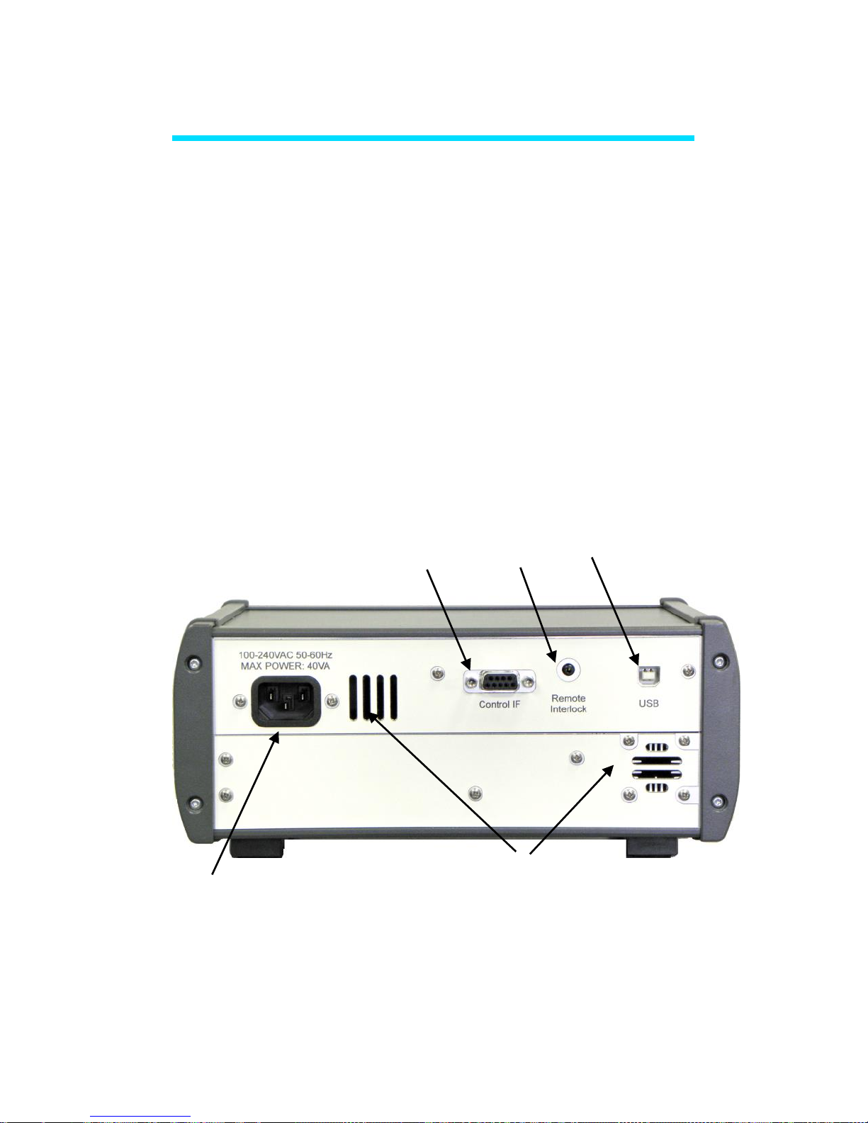
3.2 Rear-Panel Features
Refer to Figure 3.2 for the illustration of the rear-panel controls
of the BroadLighter-M.
Figure 3.2. Rear-Panel Features.
2
3
4 5 1
Page 46

BroadLighter-M Series
User Manual
Revision 16
43
1—AC POWER INPUT RECEPTACLE. It accepts a 3conductor power cord used to connect the instrument to your
local AC power line.
2—CONTROL IF CONNECTOR. Remote monitoring
of the instrument status and turning the output power on/off by
external logic. Connection cable can be provided by request.
3—REMOTE INTERLOCK (Laser Safety Measure).
This is an audio monophonic jack that is used to connect the
instrument to your local external controls for laser safety. Refer
to page 23 of this Manual for more details.
4—USB CONNECTOR. It is used to connect the
BroadLighter-M to a PC.
5—COOLING VENTS. The temperature control
system utilizes the air from the cooling vent holes.
Do not block cooling vents at the rear
panel of the instrument. Failure to do so
may result in device malfunction.
CAUTION
Page 47

3. Local Mode of Operation
44
3.3 Operating Instructions
To get started with your BroadLighter-M, carry out the following
steps in the following order:
1. Perform preparation for use. Consult section
"Preparation for Use" for more information if necessary.
2. If you have the external controls for laser safety in your
local area, connect the BroadLighter-M to your local
external controls for laser safety. Use the REMOTE
INTERLOCK jack on the rear panel of the instrument
for this connection.
3. Connect the optical patchcable supplied with the
BroadLighter-M to the front-panel FC-APC socket. The
other end of the patchcable goes to your measuring
equipment, e.g. an optical power meter. To obtain low
insertion optical losses in the instrument-to-patchcable
connection, always keep the connectors clean.
4. Turn the MASTER KEY control clockwise to position
"I". Once the key has been turned, the instrument boots
and runs an internal test to verify the statuses of the
internal components. It also checks whether the remote
interlock connection or shortening device installation is
made or not. If the test passes, POWER LED glows
green and you are able to activate the optical output of
the instrument. If the test fails, the instrument POWER
LED glows red. In this case turn the MASTER KEY to
Page 48

BroadLighter-M Series
User Manual
Revision 16
45
position “O”. Please, contact Superlum if the error
remains.
5. Enable the optical output power by pressing the
ON/OFF button. The internal speaker produces a beep
signal. There is a 3 second delay between pressing the
button and the emission activation. The button LED
switches to steady green light and the audible signal is
automatically cut off; the output emission appears at
the optical output of the instrument.
6. Verify the output power of the BroadLighter-M to be
certain that the current reading of your power meter
corresponds to the value stated in the acceptance test
report.
In order to keep the end faces of the
optical patchable clean and
protected, it is highly recommended
to avoid unnecessary
disconnections of the patchcable
from the BroadLighter-M and your
measuring equipment.
CAUTION
Page 49

3. Local Mode of Operation
46
NEVER connect optical connectors
different from those specified for your
BroadLighter-M, because they are not
intended for use with the instrument
and can seriously damage its optical
output.
1. If there is no connection between
your laser safety controls and the
instrument, remote interlock circuit
will ignore any attempt to activate
the output power.
2. Once the BroadLighter-M is turned
on, the optical output power of the
instrument can slightly drift over
time. In order to achieve greater
stability of the output power, a 30minute warm-up period is highly
recommended.
NOTE
CAUTION
Page 50

BroadLighter-M Series
User Manual
Revision 16
47
By default, the ON/OFF button
enables ALL the SLDs installed in
your instrument. You can also
select the particular SLDs to lase
by using the instrument interface
menu or via remote control
software.
3.4 Power OFF Instructions
To turn off the instrument, proceed as follows:
1. If the optical output of the instrument is active,
disable the output by pressing ON/OFF
button or via remote control if connected. The
LED on the button will go blank.
2. Turn the MASTER KEY control
counterclockwise to position "O".
3. POWER LED will go blank. The instrument is
now off.
Always disable the optical output before
turning the instrument off.
NOTE
NOTE
Page 51

3. Local Mode of Operation
48
3.5 Interface Menu
LCD screen of BroadLighter-M enables the interface menu that
allows access to the instrument features. To feel at ease with
the instrument, familiarize yourself with its main interface
screen elements and menu screen elements shown in the
figures that follow. Explanations for each feature are in the
order that they are indexed in the corresponding figures.
3.5.1 Main Interface Screen
Interface screen may vary depending on your configuration of
BroadLighter-M: standard version (Figure 3.3.1) and a version
with variable optical attenuator (VOA) / output power control
(Figure 3.3.2).
Figure 3.3.1 BroadLighter-M main interface screen. Standard
version.
1
2 3
4 5 4
5
Page 52

BroadLighter-M Series
User Manual
Revision 16
49
Figure 3.3.2 BroadLighter-M main interface screen. Version with
variable optical attenuator / output power control.
1 - INSTRUMENT STATUS BAR. This tells you the
current status of the instrument. If BroadLighter-M is ready for
emission in the local mode, status bar will display “OUTPUT
ENABLED”. Please refer to Section 3.5.2.
2 - CHANNEL STATUS. This tells you the current
status of the SLDs installed in the instrument. “SLD” refers to
the light emission by corresponding SLD. “TEC” refers to the
thermal stabilization status of the particular SLD. The actual
number of the installed SLDs depends on your particular
configuration. BroadLighter-M supports up to four SLDs. Please
refer to Section 3.5.3.
1
2
3 4 6
5
Page 53

3. Local Mode of Operation
50
3 – OUTPUT POWER. Displays the status of the output
emission. Can be “ON” or “OFF”. Version with VOA/power
control shows the output power value measured with an
integrated optical power monitor.
4—EMISSION LEVEL STATUS. This indicator is
available if your BroadLighter-M is configured with variable
optical attenuator. If the maximum output power level is
reached, the “HP” indicator will appear. If the minimum output
power level is reached, “LP” indicator will appear.
5—REMOTE CONTROL STATUS. Indicates if
REMOTE CONTROL feature is enabled.
6—OUTPUT LEVEL STATUS BAR. This indicator is
available if your BroadLighter-M is configured with variable
optical attenuator (VOA) or output power control options.
Optical output level of the output is controlled with discrete 10%
steps. Power level is controlled with NAVIGATION CONTROL
BUTTONS “Left” and “Right”. Full green bar corresponds to the
maximum output emission level. Power level can be also
controlled via remote software – see the corresponding section
in this Manual.
The BroadLighter-M version with
VOA/power control is preset to start in low
power mode. If you wish to modify that,
use Remote Control Software. Refer to
Section 4.3 of this Manual for more details.
NOTE
Page 54

BroadLighter-M Series
User Manual
Revision 16
51
1. The actual number of the installed
SLDs depends on your particular
configuration. BroadLighter-M
supports up to four SLDs.
2. BroadLighter-M has one SLD per
channel.
3. The readings of the integrated
optical power monitor are for
reference purpose only.
NOTE
Page 55
3. Local Mode of Operation
52
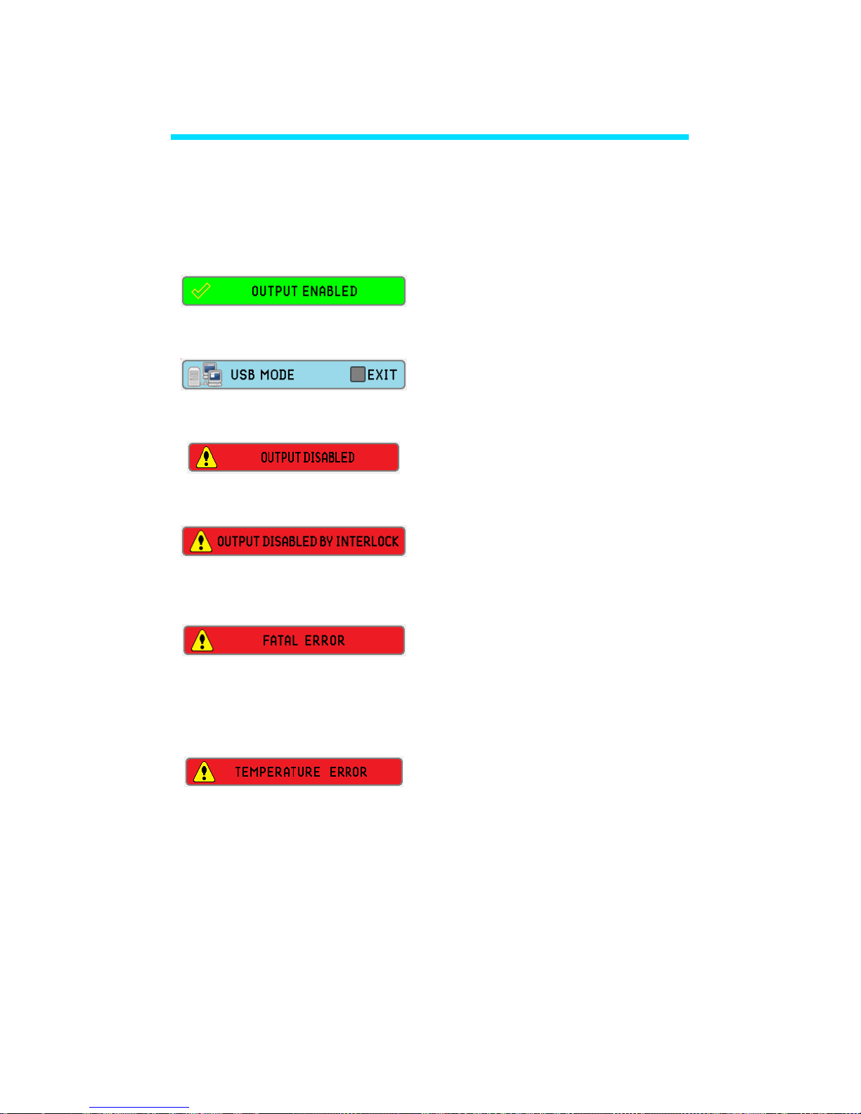
3.5.2 Main Screen Status Messages
Following status messages may appear on the BroadLighter-M
screen:
Instrument is ready for
emission
Device is connected to PC via
USB.
Emission is disabled. Check
TEC indicator in section 3.5.3.
Emission is disabled. Check
interlock connection.
Device malfunction. Contact
Superlum if the error persists
and reboot doesn’t help.
Temperature error. Turn off
the device and let it cool down.
Contact Superlum if the error
persists.
Page 56

BroadLighter-M Series
User Manual
Revision 16
53
3.5.3 Main Screen Status Indicators
Following status indicator may appear on the BroadLighter-M
main screen:
SLD is on. Status is ok.
SLD is on. Service is required. The emission may
remain, though performance parameters may degrade.
Contact Superlum if this indicator remains.
SLD malfunction. Contact Superlum if this indicator
remains.
SLD is disabled.
TEC is on. Temperature is stabilized
TEC is on. Temperature is being stabilized Please wait
until TEC is stabilized. Contact Superlum if this
indicator remains on permanently.
TEC malfunction. Contact Superlum if this indicator
remains and instrument OFF/ON doesn’t help.
TEC is disabled.
Feature is enabled.
Feature is disabled.
Page 57

3. Local Mode of Operation
54
The actual indicators and statuses are
subjects to change without notice.
Please, contact Superlum if you notice
status messages or indicators not
described in this manual.
3.5.4 Main Menu
From the main screen you can get access to the menu screen
by pressing the MENU BUTTON. You can select the interface
elements with the MENU BUTTON.
Figure 3.4. BroadLighter-M main menu.
4
1
2
3
NOTE
Page 58

BroadLighter-M Series
User Manual
Revision 16
55
1 - EXIT TO MAIN SCREEN. This brings you back to
the main interface screen.
2 - INFORMATION MENU. This provides you
information about your particular BroadLighter-M.
3 - REMOTE CONTROL. This enables or disables
REMOTE CONTROL feature.
4 - CHANNEL CONTROL. This enables or disables
particular SLDs. The number of active CHANNEL CONTROL
buttons will depend on the number of SLDs installed in your
particular BroadLighter-M.
Information Menu allows you to read the status of the
components of your BroadLighter-M:
Page 59

3. Local Mode of Operation
56
Figure 3.5. BroadLighter-M System Information menu.
It shows the information on SLDs installed in your
BroadLighter-M.
MENU CONTROL BUTTON is disabled
when the BroadLighter-M emits light.
Always turn off light emission before
modifying features in the instrument
interface.
Menu elements are subject to change
without notice. Please, contact
Superlum if you notice menu elements
not described in this manual.
Front panel controls are typically
disabled in Remote mode.
NOTE
Page 60

BroadLighter-M Series
User Manual
Revision 16
57
4. Remote Mode of Operation
Your BroadLighter-M Broadband Light Source is designed to
communicate with a PC or terminal via USB 2.0 or Remote
Control interfaces. This chapter discusses information that
explains how to control the BroadLighter-M using these
interfaces. At the end of this chapter, you will find a description
of the Superlum BroadLighter-M Companion Software, which is
supplied with the Instrument. To best serve these purposes, this
chapter has been split up into four sections covering the
following topics:
Description of Data Communication via
Remote Control Interface
Description of Data Communications via
USB Interface
Remote Command Set
Superlum BroadLighter-M Companion
Software
Section "Remote Command Set" includes subsections
that detail each command and query supported by this
equipment.
Page 61

4. Remote Mode of Operation
58
Switch OFF the BroadLighter-M before
connecting or disconnecting the
REMOTE CONTROL or USB cables.
Use only USB 2.0 Type B compatible
cable when using USB interface.
4.1 Remote Control Interface
The BroadLighter-M is equipped with the Control IF connector
located on the rear panel of the instrument. This allows the user
to operate the instrument remotely by using Logic Level
discrete signals.
The BroadLighter-M uses a female 9-pin DSUB connector for
communication via Remote Control interface.
CAUTION
Page 62

BroadLighter-M Series
User Manual
Revision 16
59
DSUB
Pin
No.
Signal
name
Description
Electrical Circuit
1
SCOM
Remote SLD
ON/OFF input,
common wire
2
SI
Remote SLD
ON/OFF input,
positive wire
3
EN
Output Enabled. If
this signal is active
– instrument is
ready for emission
4
COM
Outputs common
wire
6
PG
Power Good. If this
signal is active –
instrument is turned
on and no errors
detected.
7
ON
Emission ON. If this
signal is active –
the emission is
activated
Pin 1
Pin 2
1K
2
1
3
4
470
Pin 3
Pin 7
Pin 4
Pin 6
2
1
3
4
2
1
3
4
2
1
3
4
Page 63
4. Remote Mode of Operation
60
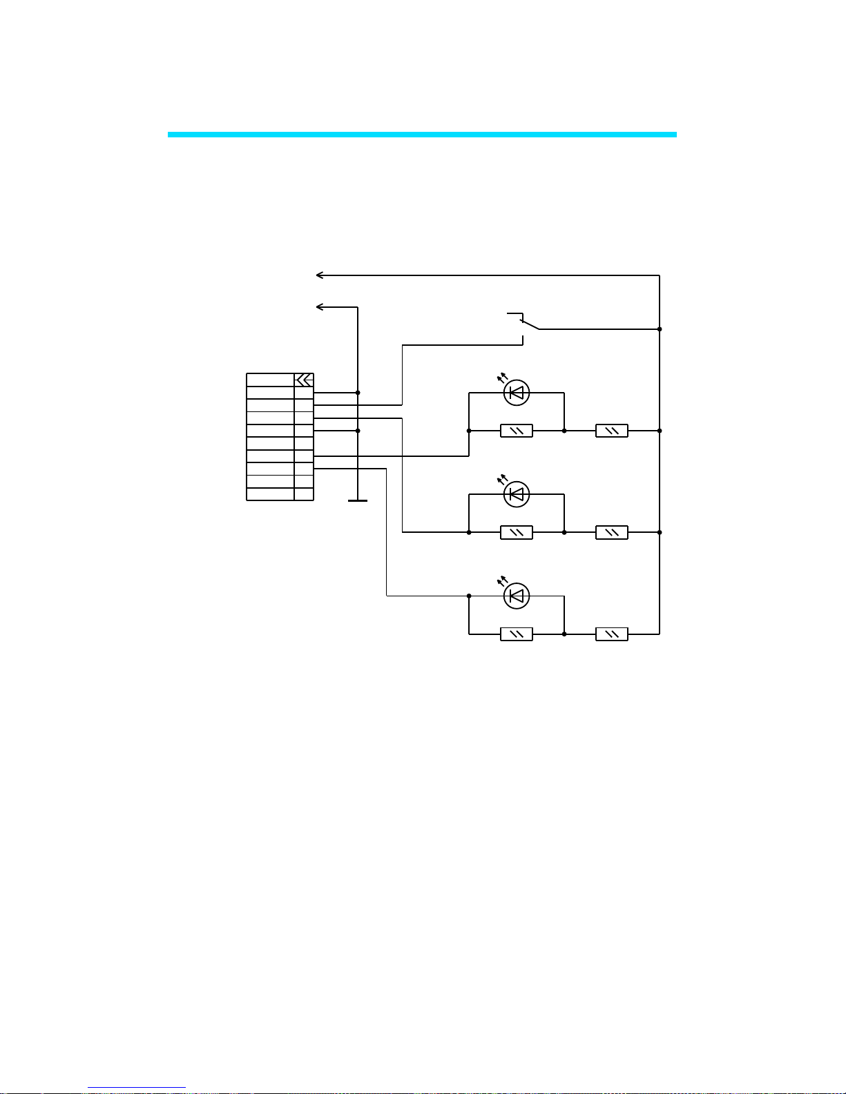
The Figure below illustrates the circuit diagram of simple
remote control terminal. This unit should be powered from
external power supply with 5 VDC output.
Figure 4.1. BroadLighter-M sample remote control circuit
diagram.
4.2 USB interface
To verify the functionality of the BroadLighter-M through the
USB interface, you can use the commands for Hyper Terminal
program commonly available on a PC. The commands are
described later in this Chapter.
ON
EN
COM
9
7
5
3
1
PG
SI
DSUB
COM
6
8
2
4
+5V
"OFF"
"PG"
X1
COM
TO
POWER
SUPPLY
"ON"
"ON"
"EN"
HL3
HL2
HL1
1
2
3
SW1
R6
1K
R5
1K
R4
1K
R3
10K
R2
10K
R1
10K
Page 64

BroadLighter-M Series
User Manual
Revision 16
61
USB connection is accomplished via virtual COM port.
The BroadLighter-M uses the FT230X USB to Serial converter
chip made by FTDI Company. Necessary drivers for common
operating systems can be downloaded using the link:
Before operating the instrument with your PC, you need
to configure the following parameters for terminal
configuration/UART configuration:
Baud Rate = 57600;
Start Bits = 1;
Stop Bits = 1;
Parity = None;
Flow Control = None.
Page 65

4. Remote Mode of Operation
62
4.2.1 System Commands
4.2.1.1 Read BroadLighter-M type, firmware version and
serial number.
Request: [I] [CR] [LF]
Acknowledge: [I] [:] [TYPE] [:] [VH] [VL] [:] [SN] [CR] [LF]
Error message: [!] [E] [CR] – common error message.
Where:
[TYPE] – Device Type, five ASCII printable chars:
“BLM-S” - one channel BroadLighter-M;
“BLM-D” - two channels BroadLighter-M;
“BLM-T” - three channels BroadLighter-M;
“BLM-Q” - four channels BroadLighter-M.
“BLM-E” – one channel BroadLighter-M with
electronic output power control option.
[VH] – Major part of firmware version [0…9], one ASCII chars;
[VL] – Minor part of firmware version [0…9], one ASCII chars;
[SN] – Serial number, six ASCII printable chars.
Page 66

BroadLighter-M Series
User Manual
Revision 16
63
4.2.1.2 Set device operation mode. Read current mode.
Request: [M] [CMD] [CR] [LF]
Acknowledge: [M] [MODE] [CR] [LF]
Error message: [!] [E] [CR] [LF] – common error message.
[CMD]
DESCRIPTION
[?]
Read current mode
[L]
Set LOCAL mode
[U]
Set USB CTRL mode
[S]
Set SERVICE mode
[MODE]
DESCRIPTION
[L]
Device operated in LOCAL mode
[U]
Device operated in USB CTRL mode
[E]
FATAL ERROR mode
[S]
Device operated in SERVICE mode
[ACCESS CODE] – [?] [?] [?] [?] Four ASCII chars needed
for entering to USB SERVICE mode
only.
Page 67

4. Remote Mode of Operation
64
4.2.2 USB Mode Commands
4.2.2.1 Switch SLD ON/OFF. Read Channel status data
Request: [U] [C] [CH] [CR] [LF]
Acknowledge: [U] [C] [IL] [ST1] [ST2] [ST3] [ST4] [CR] [LF]
Error message: [!] [E] [CR] [LF] – common error message;
[!] [M] [CR] [LF] – wrong mode set message.
[CH]
DESCRIPTION
[?]
Read Channel status data
[1]
Switch SLD#1 ON/OFF
[2]
Switch SLD#2 ON/OFF
[3]
Switch SLD#3 ON/OFF
[4]
Switch SLD#4 ON/OFF
[9]
Switch all SLDs ON/OFF
[IL] – Remote interlock data [0] or [1]:
[0] – output disabled by interlock;
[1] – output enabled.
[ST1]…[ST4] – Channel [1…4] status, [00…FF], two ASCII
chars in hexadecimal code. See table below for signal
identification.
Page 68

BroadLighter-M Series
User Manual
Revision 16
65
SIGNAL
BIT
DESCRIPTION
OME
0
‘1’ – Optical module enabled
‘0’ – Optical module disabled
TON 1 ‘1’ – TEC ON; ‘0’ – TEC OFF
TGD
2
‘1’ – Optical module temperature
stabilized
‘0’ – Optical module temperature not
stabilized
TER 3 ‘1’ – TEC (Thermistor) error
SMD
4
‘1’ – SLD operated in ACC mode
‘0’ – SLD operated in APC mode
SON 5 ‘1’ – SLD ON; ‘0’ – SLD OFF
SLM 6 ‘1’ – SLD current limit reached
SER
7
‘1’ – SLD error
Page 69

4. Remote Mode of Operation
66
4.2.2.2 Switch control
Request: [U] [S] [CMD] [CR] [LF]
Acknowledge: [U] [S] [SWDATA] [CR] [LF]
Error message: [!] [E] [CR] [LF] – common error message;
[!] [M] [CR] [LF] – wrong mode set message.
[CMD]
DESCRIPTION
[?]
Read current Switch Data
[1]
Switch Channel #1 (CH1)
[2]
Switch Channel #2 (CH2)
[3]
Switch Channel #3 (CH3)
[4]
Switch Channel #4 (CH4)
[5]
Reserved
[6]
Switch Remote Control (RC)
[7]
Switch External Modulation (EM)
[8]
Switch power meter mode (Service
mode only)
[S]
Store current Switch Data to
EEPROM
[SWDATA] – Switch status, [00…FF], two ASCII chars in
hexadecimal code. See table below for signal identification.
Page 70

BroadLighter-M Series
User Manual
Revision 16
67
[SWDATA]
DESCRIPTION
Bit#0
‘1’ – Channel #1 (CH1) enabled
‘0’ – Channel #1 (CH1) disabled
Bit#1
‘1’ – Channel #2 (CH2) enabled
‘0’ – Channel #2 (CH2) disabled
Bit#2
‘1’ – Channel #3 (CH3) enabled
‘0’ – Channel #3 (CH3) disabled
Bit#3
‘1’ – Channel #4 (CH4) enabled
‘0’ – Channel #4 (CH4) disabled
Bit#4
Reserved, reads as null
Bit#5
‘1’ – Remote Control (RC) enabled
‘0’ – Remote Control (RC) disabled
Bit#6
‘1’ – External Modulation (EM) enabled
‘0’ – External Modulation (EM) disabled
Bit#7
‘1’ – Output power mode
‘0’ – ON/OFF mode
Page 71

4. Remote Mode of Operation
68
4.2.2.3 Read measurable parameters
Read data from ADC
Request: [U] [M] [CH] [PN] [CR] [LF]
Acknowledge: [U] [M] [CH] [PN] [PDATA] [CR] [LF]
Error message: [!] [E] [CR] [LF] – common error
message;
[!] [M] [CR] [LF] – wrong mode set
message.
[CH] – Channel number [1…4], one ASCII character
[PN] – Parameter number [1…8], one ASCII character
[PDATA] – Parameter value [0000…FFFF], four ASCII
characters in hexadecimal code.
Page 72

BroadLighter-M Series
User Manual
Revision 16
69
[PN]
DESCRIPTION
PDATA RANGE
1
Real TEC current value
[0000] = 0,00A
[00FF]=+2,55A
[01FF]=-2,55A
2
SLD current (maximum
current) set value
[0000]=0,00 mA
[FFFE]=655,34mA
3
Optical module photodiode current (HP) set
value
[0000]=0,0µA
[FFFE]=6553,4µA
4
Optical module photodiode current (LP) set
value
[0000]=0,0µA
[FFFE]=6553,4µA
5
Real Optical module
temperature value
[0000]=0Ω
[FFFE]=65534Ω
6
Real SLD current value
[0000]=0,00 mA
[FFFE]=655,34mA
7
Real PD current value
[0000]=0,0µA
[FFFE]=6553,4µA
8
Optical module
temperature set point
value
[0000]=0Ω
[FFFE]=65534Ω
Page 73

4. Remote Mode of Operation
70
Note: PDATA OVELOAD VALUE IS 0xFFFF!
Temperature:
Request: [U] [T] [CR] [LF]
Acknowledge: [U] [T] [TV] [PV] [CR] [LF]
Error message: [!] [E] [CR] [LF] – common error message;
[!] [M] [CR] [LF] – wrong mode set message.
[TV] – Temperature value [00…FF], two ASCII chars in
hexadecimal code in two’s complement form:
[7F] = +127 ºC;
[00] = 0 ºC;
[FF] = -1 ºC;
[80] = -128 ºC.
[PV] – Output power value [00…FF], two ASCII chars in
hexadecimal code.
[00] = 0 mW;
[FF] = 25.5 mW.
4.2.2.4 Attenuator and output power control
If VOA option is installed, the VOA transmission is controlled.
Otherwise SLD output is controlled.
Page 74

BroadLighter-M Series
User Manual
Revision 16
71
Request: [U] [A] [CMD] [CR] [LF]
Acknowledge: [U] [A] [POS] [CR] [LF]
Error message: [!] [E] [CR] [LF] – common error message;
[!] [M] [CR] [LF] – wrong mode set message.
[CMD]
DESCRIPTION
[?]
Read current attenuator position
[0…9]
Set attenuator position
[S]
Store current position as default
[T]
Switch HP/LP mode (not
implemented)
ATTENUATOR POSITION
[POS]
OUTPUT
POWER
NOTE
0
Max Power
(100 %)
“HP
3
”
1
90 %
--
2
80 %
-- 3 70 %
-- 4 60 %
-- 5 50 %
--
6
40 %
--
7
30 %
-- 8 20 %
--
9
Min Power (10
%)
“LP
4
”
Command not implemented in REV_1.X
BroadLighter-M.
3
HP – high power mode
4
LP – low power mode
Page 75

4. Remote Mode of Operation
72
4.2.2.5 Read Optical unit type, firmware version and
serial number
Request: [U] [O] [CR] [LF]
Acknowledge: [U] [O] [TYPE] [WL] [VERSION] [SN] [CR] [LF]
Error message: [!] [E] [CR] [LF] – common error message;
[!] [M] [CR] [LF] – wrong mode set message.
[TYPE] – Optical unit type [00…FF] two ASCII chars in
hexadecimal code, see table below:
Bit #7
Bit #6
Bit #5
Bit
#4
Bit #3
Bit #2
Bit #1
Bit #0
MOD
ATT
OPM
ISO
OM4
OM3
OM2
OM1
OM [4…1] – optical module presence sign:
– ‘0’ – module not installed;
– ‘1’ – module installed;
ISO – optical isolator presence sign:
– ‘0’ – isolator not installed;
– ‘1’ – isolator installed;
OPM – output power monitor presence sign:
– ‘0’ – OPM not installed;
Page 76

BroadLighter-M Series
User Manual
Revision 16
73
– ‘1’ – OPM installed;
ATT – optical attenuator presence sign:
– ‘0’ – attenuator not installed;
– ‘1’ – attenuator installed;
MOD – optical modulator presence sign:
– ‘0’ – modulator not installed;
– ‘1’ – modulator installed;
[WL] – Central wavelength value [00…FF], two ASCII
chars in hexadecimal code:
[00] = 0 = 0 nm;
[FF] = 255 = 2550 nm;
[VERSION] – Firmware version, [01…99] two ASCII chars;
[SN] – Optical unit serial number, six ASCII printable chars.
4.2.2.6 Read Optical Module parameter
Request: [U] [P] [MN] [PN] [CR] [LF]
Acknowledge: [U] [P] [MN] [PN] [DATA] [CR] [LF]
Error message: [!] [E] [CR] [LF] – common error
message;
Page 77

4. Remote Mode of Operation
74
[!] [M] [CR] [LF] – wrong mode set
message.
[MN] – Optical module number, [1…4] (One ASCII
character);
[PN] – Parameter number, [0…9] (One ASCII
character);
[DATA] – Parameter data, see table below.
[PN]
Description
DATA Range
Comments
0
Optical module
serial number
[XXXXXX]
Six ASCII
printable
characters
1
Optical module
operation mode
[0] or [1], one
ASCII char
[0] – APC mode
[1] – ACC mode
2
Optical module
temperature set
point value
[0000…FFFE],
four ASCII chars
[0000] = 0 ohm
[FFFF] = 65534
ohm
3
Optical module
maximum current
value
[0000…270F],
four ASCII chars
[0000] = 0,0 mA
[270F] = 999,9
mA
4
Optical module
current value
[0000…270F],
four ASCII chars
[0000] = 0,0 mA
[270F] = 999,9
mA
5
Optical module
photo-diode
current value (HP)
[0000…270F],
four ASCII chars
[0000] = 0 µA
[270F] = 9999
µA
6
Optical module
photo-diode
current value (LP)
[0000…270F],
four ASCII chars
[0000] = 0 µA
[270F] = 9999
µA
9
Optical module
operating time
[00000000][FFFFFFFF],
Eight ASCII
chars
00000000 – 0 s;
0000000A – 10
s;
….
Note: Switch off SLD before reading the optical module
operating time value.
Page 78

BroadLighter-M Series
User Manual
Revision 16
75
4.2.2.7 Read temperature and output power
Request: [U] [T] [CR] [LF]
Acknowledge: [U] [T] [TV] [PV] [CR] [LF]
Error message: [!] [E] [CR] [LF] – common error message;
[!] [M] [CR] [LF] – wrong mode set
message.
[TV] – Temperature value [00…FF], two ASCII chars in
hexadecimal code in two’s complement form:
[7F] = +127 ºC;
[00] = 0 ºC;
[FF] = -1 ºC;
[80] = -128 ºC.
For Rev_1.X BroadLighter-M ONLY:
[PV] – Output power value [00…FF], two ASCII chars in
hexadecimal code.
[00] = 0 mW;
[FF] = 25,5 mW.
For Rev_2.X BroadLighter-M:
[PV] – Output power value [000…FFF], three ASCII chars
in hexadecimal code.
[000] = 0 mW;
[FFF] = 409,5 mW.
Page 79

4. Remote Mode of Operation
76
4.2.2.8 Read output power limit
Request: [U] [L] [CR] [LF]
Acknowledge: [U] [L] [PL] [CR] [LF]
Error message: [!] [E] [CR] [LF] – common error message;
[!] [M] [CR] [LF] – wrong mode set
message
[PL] – Output power LIMIT value, [00…FF], two ACSII
characters in hexadecimal code: [00] = 0 mW;
[FF] = 255 mW.
Page 80

BroadLighter-M Series
User Manual
Revision 16
77
4.3 Superlum Companion Software
The interface of this program includes the same features which
you can find on the front panel of the instrument. Using these
features of the program allows you to control the BroadLighterM remotely from your PC system instead of standing in front of
the instrument.
By using this program, you can do the following:
Activate and deactivate each SLD module
individually.
Activate and deactivate several SLD modules
simultaneously.
Monitor the current status of the instrument
controls
By clicking on the necessary button in the
program window, automatically measure and
save all current values of the instrument
performance parameters to a separate file on
your PC which must be forwarded to Superlum
when you suspect problems with the
BroadLighter-M.
Page 81

4. Remote Mode of Operation
78
It is important to note that the last feature in the list
above is accessible through the program only.
The program features very simple installation, nonsevere system requirements, and a user-friendly interface. Use
this program whenever you want to do the following:
To begin to control the BroadLighter-M
remotely as soon as you receive it and do not
want to waste much time for developing the
program of your own.
In the case of a problem: to test the instrument
performance and report the results of the test
to Superlum for getting the necessary
assistance.
4.3.1 Minimum System Requirements
Minimum system requirements are as follows:
Operating system: Windows 95, 95 OSR2, 98, or
98 SE, Windows ME, Windows NT Workstation 4.0
Service Pack 3, Windows 2000 Professional,
Windows XP, Windows Vista, Windows 7.
Memory: 32 MB for Windows 9x and ME, 64 MB
for Windows NT and 128 MB for Windows 2000
Page 82

BroadLighter-M Series
User Manual
Revision 16
79
and XP, 1 gigabyte (GB) (32-bit) or 2 GB (64-bit)
for Windows Vista and Windows 7/8/8.1.
Processor: 100-megahertz (MHz) or faster
processor for Windows 9x and ME, 300-megahertz
(MHz) or faster processor for Windows 2000 and
XP, 1 gigahertz (GHz) or faster 32-bit (x86) or 64bit (x64) processor for Windows Vista and
Windows 7,
Hard disk space: 10MB of free hard disk space.
Miscellaneous: USB 2.0 interface.
4.3.2 Installing the USB drivers
Prior to connecting BroadLighter-M to PC via USB and/or
installing the Companion Software, the USB drivers must be
installed. Necessary drivers for common operating systems can
be downloaded using the link:
http://www.ftdichip.com/Drivers/VCP.htm
BroadLighter-M must not be connected to the PC while
installing the drivers. Insert the CD that was supplied with your
unit into your PC. Select the driver software and run it. Follow
the onscreen prompts to install the driver. After the driver is
installed, connect BroadLighter-M to the PC and power it on.
Page 83

4. Remote Mode of Operation
80
Your PC will detect the new hardware and will prompt you when
the installation is complete.
If you experience problems installing
the USB drivers, please contact your
system administrator.
4.3.3 Installing Companion Software
Copy the executable file from the CD provided with your
BroadLighter-M to the destined folder on your PC. Some
systems may require Administrative rights to run Superlum
software. Contact your system administrator for more
information.
BroadLighter-M uses virtual COM-port connection for PC
communication via USB interface. During the first run of the
software, virtual COM port associated with your BroadLighterM has to be selected. After COM port is selected, software Start
Screen will appear.
NOTE
Page 84

BroadLighter-M Series
User Manual
Revision 16
81
Figure 4.1. BroadLighter-M Companion Software. COM port
selection associated with BroadLighter-M.
4.3.4 User Interface
Companion Software for BroadLighter-M enables the interface
menu that allows access to the instrument features. To feel at
ease with the software interface, familiarize yourself with its
main interface elements shown in the figures that follow.
Explanations for each feature are organized as they are
indexed in the corresponding figures.
Figure 4.2. BroadLighter-M Companion Software Start
Screen.
1
2
3
Page 85

4. Remote Mode of Operation
82
1—Connection. It is used to select the virtual COM
port.
2—Close. It is to quit Companion Software.
3—USB mode. It is used to connect to BroadLighter-M
and switch between Local and USB modes.
Connect to BroadLighter-M by pressing USB mode
button. Once BroadLighter-M is successfully connected, Start
Screen will be replaced with the Interface Screen. The new
interface elements are:
Figure 4.3. BroadLighter-M Companion Software Interface
Screen.
1—Device information. Information screen that
shows you the instrument temperature and the output optical
power readings.
2—Self Test. Automatic Diagnostic Procedure which is
normally required only when the device doesn’t work properly.
1
2
5
3
8
7
8
4 5 6
9
10
Page 86

BroadLighter-M Series
User Manual
Revision 16
83
In this unlikely scenario, Superlum will provide you with more
information on the topic. Please be aware that once selected,
the Self Test Procedure can’t be cancelled.
3—Service Indicator. It is on when there is a service
required for the SLDs installed in your BroadLighter-M. Please
contact Superlum if this indicator is permanently on. The actual
number of indicators will depend on a number of SLDs installed
in your BroadLighter-M.
4—SLD ON/OFF. Allows you to turn the emission on
for all the enabled SLDs simultaneously. The indicator is green
when the emission is on. There is a 3 second time delay
between pressing the emission ON/OFF button and the
emission activation.
5—Remote Interlock Indicator. Shows you whether
the Interlock is activated.
6—Features Menu. Allows you to enable and disable
the features available for your BroadLighter-M. This menu is
only available when the emission is off.
8—Save. Saves the current configuration selected in
Features Menu. The menu is only available when the emission
is off.
9—Output level control bar. FOR BROADLIGHTERM VERSIONS WITH VOA / POWER CONTROL ONLY. Allows
for output level control with 10 discrete steps. Each step
represents 10% change in output power.
Page 87

4. Remote Mode of Operation
84
10—Set as Default. Saves current power level setting
as a default for the next instrument start up.
By default, BroadLighter-M with VOA /
power control option is preset to start
with 10% of output power. Using
Remote Control Software User can
select default start output level by
selecting appropriate control bar
position and pressing “Set as Default”
button.
This is only for BroadLighter-M
instruments with VOA / power control
option. Standard versions operate at
100% output power by default.
4.3.5 Self Test Procedure
Self test generates BroadLighter-M diagnostics report file that
can be used for instrument status analysis. If the self test
procedure is selected, the following warning window will
appear:
NOTE
Page 88

BroadLighter-M Series
User Manual
Revision 16
85
Figure 4.4. BroadLighter-M Companion Software self test
warning.
Disconnect the optical patchcable from the instrument and put
a protective cap on FC/APC connector. Press OK to continue.
The self test procedure will start automatically. Do not disturb it
or shut down the instrument during the automatic self test
procedure. You will see the self-updated window:
Figure 4.5. BroadLighter-M Companion Software self test
window.
Page 89

4. Remote Mode of Operation
86
Once the self test is complete the software will inform you. Save
the file in the folder of your choice. The procedure is now
complete.
4.3.6 Uninstalling the Program
To uninstall the Superlum BroadLighter-M companion software
from your PC, just remove its files from the folder created during
the installation.
Page 90

BroadLighter-M Series
User Manual
Revision 16
87
5. Cleaning Instructions
This chapter will advise you on the cleaning procedures
acceptable for the BroadLighter-M Broadband SLD Benchtop
Light Source. With regular cleaning you will be able to keep
your BroadLighter-M in the best operating conditions, thereby
ensuring its excellent performance.
5.1 Safety Precautions
This section details the general safety precautions you need to
observe during all phases of operating and cleaning the
BroadLighter-M.
First of all, you should pay close attention to following
common recommendations:
Whenever possible, use physical contact connectors and
dry connections.
Clean the connectors, interfaces, and sleeves regularly
after use.
If you are unsure of the correct cleaning procedure for
your optical device, it is highly recommended that you
first try cleaning a dummy or test device.
Before you begin cleaning the BroadLighter-M, please
read the following safety rules:
Page 91

5. Cleaning Instructions
88
1. Do not remove instrument covers when cleaning.
2. Make sure that you disable the optical output of the
instrument before cleaning any optical interfaces.
3. Under no circumstances look into the end of an optical
patchcable attached to the optical output of the
BroadLighter-M when the instrument is operated.
Instrument emission is not visible to the human eye, but
it may seriously damage your eyesight.
4. When cleaning, always do the following:
• To prevent electrical shock, disconnect the
instrument from AC power line before cleaning.
• To clean external parts of the instrument cabinet,
use a dry cloth or a cloth slightly dampened with
water.
• Do not attempt to clean internally.
5. Do not open the BroadLighter-M to perform any
servicing to the instrument.
6. Do not install parts or perform any unauthorized
modification to the BroadLighter-M.
7. In case of some problems with the instrument, contact
Superlum for assistance. (Refer to the chapter 6 for
more information on obtaining service.)
Page 92

BroadLighter-M Series
User Manual
Revision 16
89
5.2 Cleaning
This section advises on the cleaning procedures for
BroadLighter-M. Optical connectors may require at least two
cleanings. The initial cleaning gently removes any grit and oil.
If filmy deposits are still present at an optical interface, the
second cleaning should be performed. It is not uncommon for a
patchcable or connector to require more than one cleaning.
1. Never look into the end of an optical
aperture or optical patchcable when
the BroadLighter-M is operational.
2. Always disable the optical output of
the instrument before cleaning the
optical connectors.
WARNING
Page 93

5. Cleaning Instructions
90
1. To clean optical fiber ends, use
natural cotton swabs or specialized
fiber-optic cleaning equipment.
2. If you use compressed air for the
cleaning, make sure that
compressed air is free from dust,
water, and oil.
3. Be especially careful when
inserting the ferrule of a patchcable
into a connector or adapter. Make
sure that it does not touch the
outside of the mating connector or
adapter.
4. Never use a cotton swab to dry the
adapter inside, because it may
damage internal parts of the optical
adapter.
CAUTION
Page 94

BroadLighter-M Series
User Manual
Revision 16
91
1. If possible, avoid using denatured
alcohol because it usually contains
additives. Instead, apply alcohol
that is used for medical purposes.
2. Always recap the optical output of
the BroadLighter when it is not in
use.
3. Apply as little alcohol as needed for
cleaning. This allows you to avoid
getting any amount of alcohol
inside the optical adapter. If, after
all, the adapter contains some
alcohol after cleaning, use
compressed air for drying it.
NOTE
Page 95

6. Service and Support
92
6. Service and Support
This chapter contains detailed information on what you should
do if you need to have your BroadLighter-M serviced.
6.1 Returning the Instrument for Servicing
The instructions in this section will explain to you how to
properly return the instrument for repair or calibration. Always
call or email Superlum to initiate service before returning your
instrument. This ensures that the time for the repair or
calibration is reserved and that your instrument will be returned
to you as quickly as possible. If the instrument is still under
warranty, it will be repaired under the terms of the warranty.
Please see section "Warranty" at the beginning of the manual.
If the BroadLighter-M is no longer under warranty, Superlum will
notify you of the cost of the repair after examining the device.
When the instrument is returned to Superlum for
servicing, it must be adequately packaged and have a complete
description of the failure symptoms attached. When describing
the failure, please be as specific as possible about the nature
of the problem. Include copies of additional failure information such as the instrument failure settings, data related to
instrument failure, etc., along with the instrument being
returned.
Page 96

BroadLighter-M Series
User Manual
Revision 16
93
6.2 Preparing the Instrument for Shipment
To properly prepare the instrument for shipment, observe the
following instructions:
1. Write a complete description of the failure and attach it
to the instrument. Include any specific performance
details related to the problem.
The following information should be returned with the
instrument:
• Type of service required: repair or calibration
• Date of the failure
• Description of the problem:
o Whether problem is constant or
intermittent
o Whether instrument is temperature-
sensitive
o Whether instrument is vibration-sensitive
o Instrument settings required to reproduce
the problem
o Performance data
• Your Company name and return address
• Name and phone number of a technical contact
person
• Model number and serial number of the returned
instrument
• List of any accessories returned with the instrument
2. Cover all front or rear-panel connectors that were
originally covered when you first received the
instrument.
Page 97

6. Service and Support
94
3. Pack the instrument in the original shipping container,
or use an adequate replacement following the
directions below:
• Wrap the instrument in antistatic plastic to reduce the
possibility of damage caused by electrostatic
discharge.
• Use a double-walled, corrugated cardboard carton to
pack the instrument.
• The carton must be large enough to allow
approximately 7 cm on all sides of the instrument for
packing material, and strong enough to
accommodate the weight of the instrument.
• Surround the equipment with packing material to
protect the instrument and prevent it from moving in
the carton. The best solution is to use Air Cap™. Air
Cap™ looks like a plastic sheet filled with air bubbles.
Use the pink (antistatic) Air Cap™ to reduce static
electricity. Wrapping the instrument several times in
this material will protect the instrument and prevent it
from moving in the carton.
4. Seal the carton with strong nylon adhesive tape.
5. Mark the carton "FRAGILE, HANDLE WITH CARE".
6. Retain copies of all shipping papers.
Page 98

BroadLighter-M Series
User Manual
Revision 16
95
1. Cover optical connectors to protect
them from damage caused by
physical contact or dust.
2. Never use styrene pellets as
packaging material. They do not
adequately cushion the instrument
or prevent it from shifting in the
carton. They may also cause
instrument damage by generating
static electricity.
6.3 Instrument Disposal
If you wish to dispose the instrument, you must hand it to a
specialized waste recovery company. Do not dispose of the unit
in a litter bin or at a public waste disposal site.
NOTE
 Loading...