

Page 1
Series S Infrared Heater
If you smell gas:
1. Open windows
2. Don’t touch electrical switches
3. Extinguish any open flame
4. Immediately call your gas
supplier
FOR YOUR SAFETY
Do not store or use gasoline or
other flammable vapors and liquids
in the vicinity of this or any other
appliance.
FOR YOUR SAFETY
Si vous sentez une odeur de gaz:
1. Ouvrez les fenetres
2. Ne touchez pas aux interupteurs
electriques
3. Eteignez tout flamme nue
4. Contactez immediatment votre
CONSIGNES DE SECURITE
Il est interdit d’utiliser des liquides
inflammables ou degageant des
vapeurs inflammables, a proximites
de tout appareil fonctionnent au
gaz.
CONSIGNES DE SECURITE
WARNING
Installation, Operation and Service Instructions
Read and thoroughly understand these instructions before attempting any installation.
Improper installation, adjustment, alteration, service or maintenance can cause injury, death or property
damage. Read the installation, operation and service instructions thoroughly before installing or servicing
Installer
Owner
Retain this manual for reference.
this equipment.
Superior Radiant Products
www.superiorradiant.com
01/15 LT017
Page 2
CAUTION: FIRE OR EXPLOSION HAZARD
Maintain clearance to combustible constructions as further specified in this manual.
Failure to do so could result in a serious fire hazard. Heaters should not be located in
hazardous atmospheres containing flammable vapors or combustible dusts. Signs should
be provided in storage areas specifying maximum safe stacking height.
CAUTION: MECHANICAL HAZARD
This equipment is designed and approved for indoor use only.
CAUTION: FIRE OR EXPLOSION HAZARD
This heater is equipped with an automatic ignition device. Do not attempt to light the
burner by hand. Failure to comply could result in a serious fire and personal injury
hazard.
CAUTION: MECHANICAL HAZARD
Do not use high pressure (above ½ psi) to test the gas supply system with the burners
connected. Failure to do so could result in damage to the burner and its control
components requiring replacement.
CAUTION: SERVICE LIFE RISK
Do no install equipment in atmospheres containing halogenated hydrocarbons or other
corrosive chemicals. High intensity heaters are not recommended for installation in
enclosed swimming pool areas. Failure to do so may lead to premature equipment
failure and will in-validate the warranty.
Page 3

TABLE OF CONTENTS
INTRODUCTION ________________________________________________________________________ 4
Installation Codes ____________________________________________________________________________ 5
General Installation and Gas Codes/Electrical Codes _________________________________________________________ 5
Aircraft Hangar Installation ______________________________________________________________________________ 5
Public Garages ________________________________________________________________________________________ 5
Parking Structures _____________________________________________________________________________________ 5
LAYOUT RECOMMENDATIONS ____________________________________________________________ 6
Layout Considerations ________________________________________________________________________ 6
Spot Heating ________________________________________________________________________________ 6
Full Building Heat ____________________________________________________________________________ 7
HEATER SPECIFICATIONS _________________________________________________________________ 8
Dimensional Chart ___________________________________________________________________________ 8
Gas Supply _________________________________________________________________________________ 9
Electrical Requirements _______________________________________________________________________ 9
CLEARANCE TO COMBUSTABLES __________________________________________________________ 10
INSTALLATION ________________________________________________________________________ 11
Gas ______________________________________________________________________________________ 11
Electric ___________________________________________________________________________________ 12
VENTILATION / CONDENSATION __________________________________________________________ 14
Ventilation ________________________________________________________________________________ 14
Condensation ______________________________________________________________________________ 14
OPERATION / MAINTENENCE ____________________________________________________________ 15
Operation _________________________________________________________________________________ 15
Control Operating Sequence—Direct Spark Ignition _________________________________________________________ 15
Annual Maintenance ________________________________________________________________________ 15
TROUBLESHOOTING ____________________________________________________________________ 16
PARTS _______________________________________________________________________________ 17
WARRANTY __________________________________________________________________________ 18
Series S Page - 3 - March 4, 2014
Page 4

Important
These instructions, the layout drawing, local codes and ordinances, and applicable standards such as
apply to gas piping and electrical wiring comprise the basic information needed to complete the
installation, and must be thoroughly understood along with general building codes before proceeding.
Only personnel who have been trained and understand all applicable codes should undertake the
installation. SRP Representatives are Factory Certified in the service and application of this
equipment and can be called on for helpful suggestions about installation.
INTRODUCTION
Superior Radiant Products is a company in the infrared heating industry founded on the principles of product
quality and customer commitment.
Quality commitments are evidenced by superior design, a regard for design detail and an upgrade of
materials wherever justifiable.
Customer commitment is apparent through our ready responses to market demands and a never-ending
training and service support program for and through our distributor network.
Series S Page - 4 - March 4, 2014
Page 5

INTRODUCTION
Installation Codes
Installations must comply with all local building codes or in their absence; the latest edition of the national
regulations and procedures applicable to gas fired and suspended heaters.
General Installation and Gas Codes/Electrical Codes
Heaters must be installed only for use with the type of gas appearing on the rating plate, and the
installation must conform to the National Fuel Gas Code, ANSI Z.223.1 (NFPA 54) in the US and
CAN/CGA B149.1 and B149.2 Installation Codes in Canada. For electrical requirements refer to the
latest editions of the National Electrical Code ANSI/NFPA 70 or Canadian Electrical Code C22.1
This heater maybe approved for either indoor or outdoor installation. Not for use in residential
dwellings, refer to Rating plate.
Aircraft Hangar Installation
Installation in aircraft hangars must conform to the Standard for Aircraft Hangars, ANSI/NFPA 409 in
the US and CAN/CGA B149.1 and B149.2 Installation Codes in Canada
Public Garages
Installation in public garages must conform to the Standard for Parking Structures, NFPA 88A or the
Standard for Repair Garages, NFPA 88B, in the US and CAN/CGA B149.1 and B149.2 Installation
Codes in Canada.
Parking Structures
Technical requirements are outlined in ANSI/NFPA 88A (USA)
Series S Page - 5 - March 4, 2014
Page 6
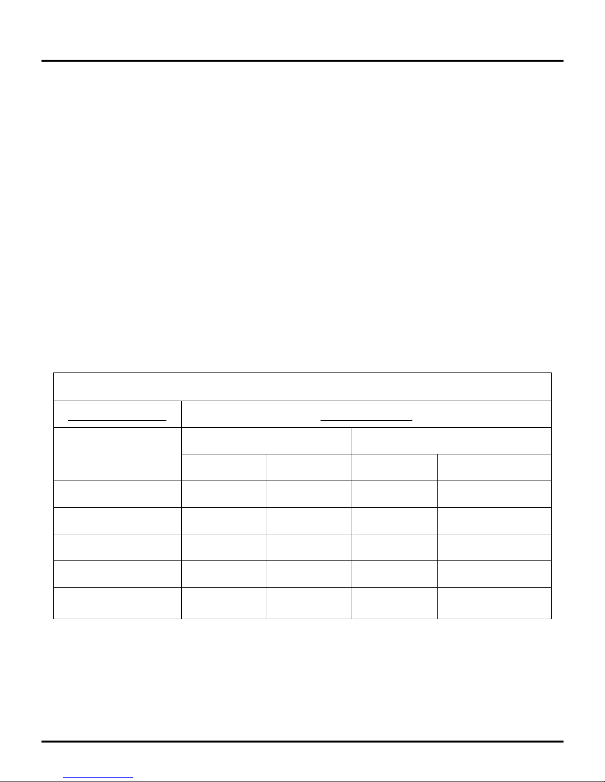
LAYOUT RECOMMENDATIONS
Suggested Minimum Mounting Heights
Heater Input Rate
Mounting Angle
BTU/hr
10°
35°
ft m ft
m
30,000-33,000
11 – 13
3.4 – 4.0
10 - 12
3.1 – 3.6
60,000-66,000
14.5 – 16.5
4.5 – 5.0
13 – 15
4.0 – 4.5
90,000-99,000
16 – 18.5
4.9 – 5.6
14.5 – 17
4.5 – 5.2
120,000-132,000
17.5 – 21
5.4 – 6.4
15.5 – 18.5
4.7 – 5.6
160,000
19 – 23
5.8 – 7.0
17 - 21
5.2 – 6.4
Layout Considerations
1. Because high intensity heaters are un-vented, verify local codes for guidance on air supply and
dilution air. Also see section on Ventilation.
2. Check local codes for mounting requirements and the requirement for flexible gas connectors or rigid
mounting.
3. Do not locate heaters near windy locations such as door openings.
4. Do not locate heaters in very dusty environments
5. Avoid placing heaters below sprinkler heads or provide more than adequate clearance.
Spot Heating
High intensity heaters are ideal for spot heating applications. The following are key considerations to
the success of the application:
1. Minimize any wind in order to maximize the effect of the radiant heat.
2. Placing two smaller heaters opposing each other will be more comfortable than placing one
large heater.
3. Hang the heaters back and at an oblique angle (rather than directly overhead) in order to
maximize the exposure of the peoples’ bodies to radiant heat.
The following charts are intended for guidance only. Specific applications may require other parameters.
Series S Page - 6 - March 4, 2014
Page 7
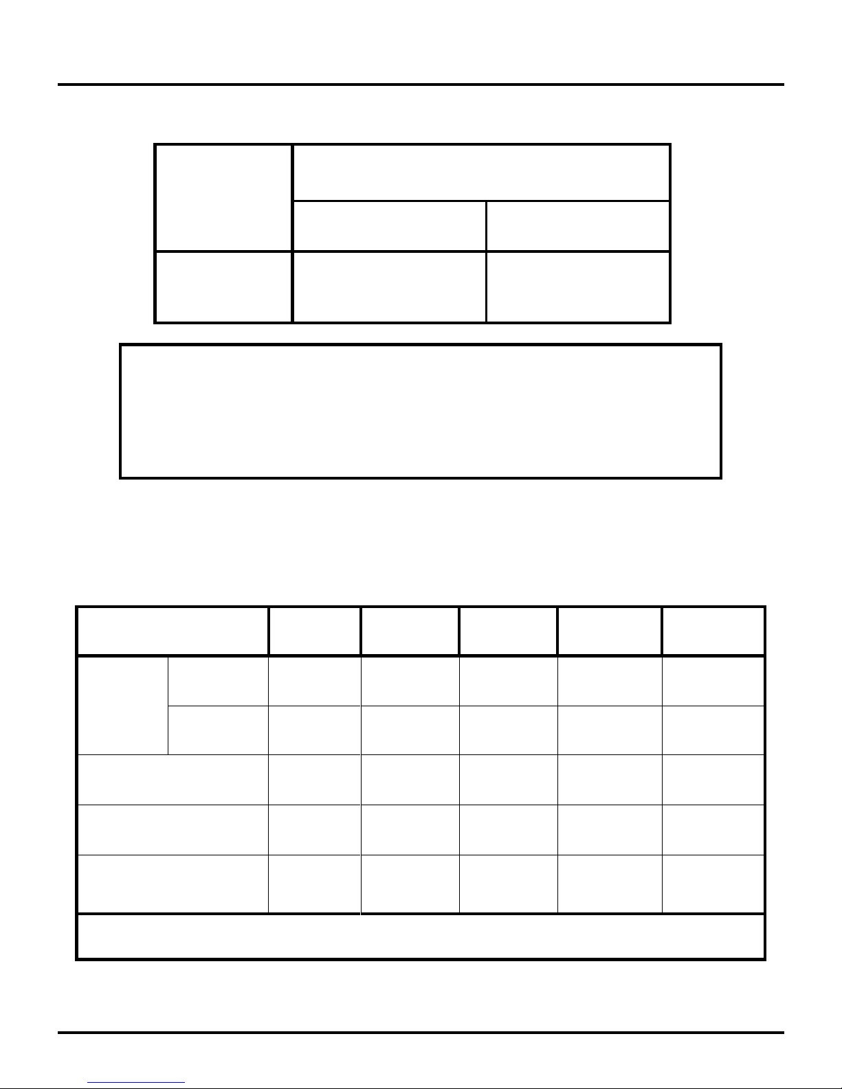
LAYOUT RECOMMENDATIONS
Ambient Air
Temperature
BTU/hr per sq. ft of
Floor Area to be Heated
At 50 ft/min of wind
(15.2 m/min)
At 100 ft/min of wind
(30.5 m/min)
40°F / 4°C
150—165
165—180
55°F / 13°C
75—88
85—100
Example:
Work counter for light assembly, space is 15 ft x 25 ft. (4.5 m x 7.6 m), ambient air
temperature 40°F / 4C, located near shipping doors.
Approximately 170 BTUH/sq.ft x (15x25) sq.ft = 63,750 BTUH
Two heaters at opposing locations would be preferred
Model/BTUH
S3
30-33,000
S6
60-66,000
S9
90-99,000
S12
120-132,000
S16
160,000
Heater
Mounting
Height,
ft (m)
Mounting
Angle 10°
11-15
(3.4 – 4.6)
15-20
(4.6 – 6.1)
20-25
(6.1 – 7.6)
25-30
(7.6 – 9.2)
30-38
(9.2 – 11.6)
Mounting
Angle 35°
10-12
(3.1 – 3.6)
13-16
(4.0 – 4.9)
16-22
(4.9 – 6.7)
18-26
(5.5 – 7.9)
24-31
(7.3 – 9.4)
Distance of first heater row
from outside wall, ft (m)
6
(1.9)
10
(3.1)
12
(3.7)
14
(4.3)
16
(4.9)
Distance between heaters
along outside wall*, ft (m)
8-20
(2.5 – 6.1)
15-30
(4.6 – 9.2)
20-40
(6.1 – 12.2)
30-50
(9.2 – 15.2)
40-60
(12.2 – 18.3)
Distance between rows –
out-side wall row to next
interior row, ft (m)
30-60
(9.2 – 18.3)
50-80
(15.2 – 24.4)
75-110
(22.9 – 33.5)
90-115
(27.5 – 35.0)
100-125
(30.5 – 38.1)
* Distance between heaters along interior rows should be up to twice the indicated number
Suggested heat loading for indoor spot heating under stated conditions:
Full Building Heat
Calculate the total heat input required, ensuring the inclusion of any unheated make-up air due to exhaust
fans. Use the following chart as guidance to heater placement.
Series S Page - 7 - March 4, 2014
Page 8
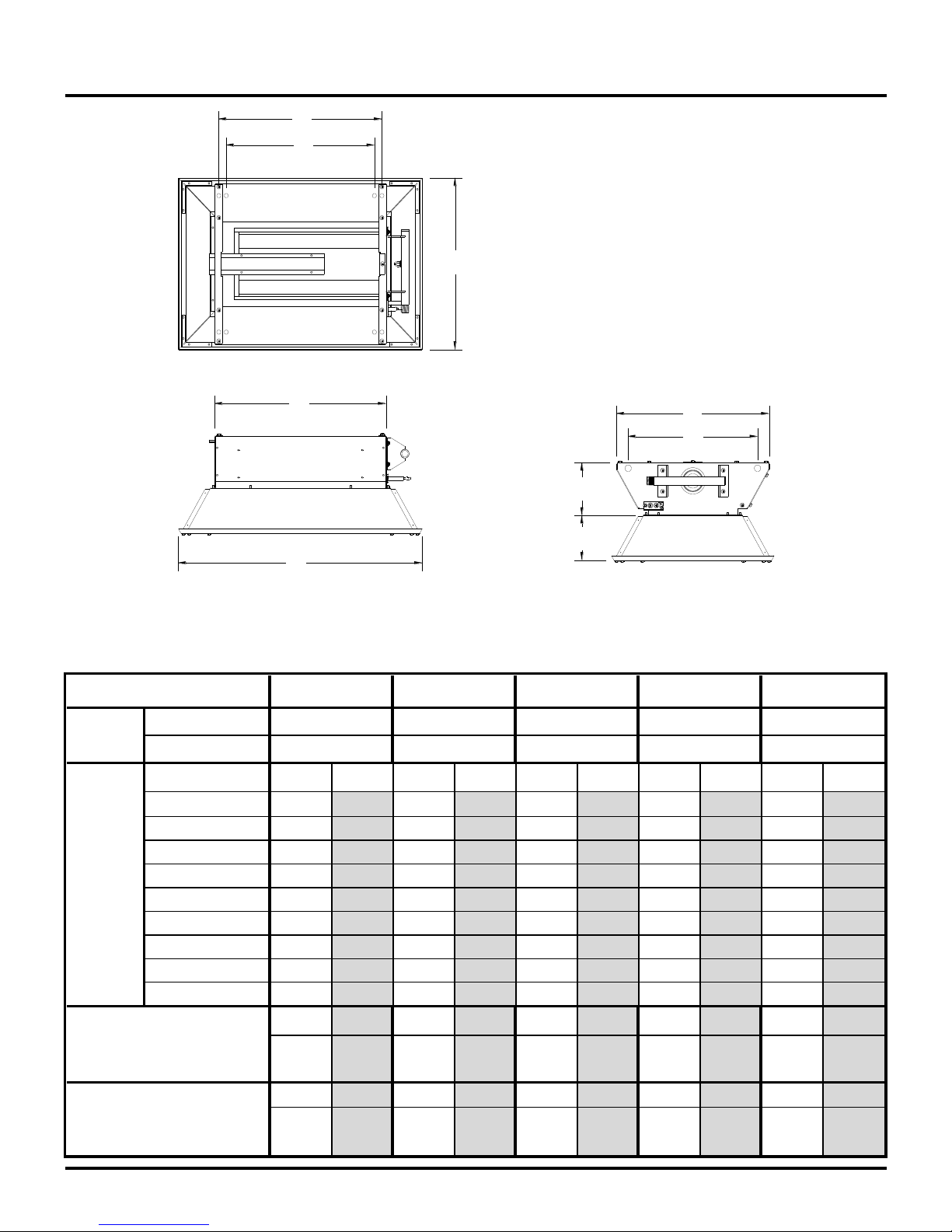
B
H
F
E
C
G
D
J
A
HEATER SPECIFICATIONS
Natural Gas
Propane Gas
in cm in cm in cm in cm in cm
A
16.3 41.4 23.1 58.7 30 76.2 36.9 93.7 36.9 93.7
B 24.4 62 24.4 62 24.4 62 24.4 62 24.4 62
C 4.2 10.7 4.2 10.7 4.2 10.7 4.2 10.7 4.2 10.7
D 12.9 32.8 19.8 50.3 26.7 67.8 33.6 85.4 33.6 85.4
E 14.8 37.6 14.8 37.6 14.8 37.6 14.8 37.6 14.8 37.6
F 16.3 41.4 16.3 41.4 16.3 41.4 16.3 41.4 16.3 41.4
G 5 12.7 5 12.7 5 12.7 5 12.7 5 12.7
H 17.1 43.4 17.1 43.4 17.1 43.4 17.1 43.4 17.1 43.4
J
15.2 38.6 22.1 56.1 29 73.7 35.9 91.2 35.9 91.2
in
2
cm
2
in
2
cm
2
in
2
cm
2
in
2
cm
2
in
2
cm
2
90 581 180 1161 270 1742 360 2323 360 2323
lbs Kg lbs Kg lbs Kg lbs Kg lbs Kg
29 13.2 40 18.2 48 21.8 59 26.8 59 26.8
Shipping Weight
N/A
Input
BTU/hr
33,000
66,000
99,000
132,000
160,000
30,000
60,000
90,000
120,000
DIMENSION
Radiating Surface Area
S16
Model #
S3S6S9
S12
Figure 1: Overall Dimensional Information
Dimensional Chart
Series S Page - 8 - March 4, 2014
Page 9
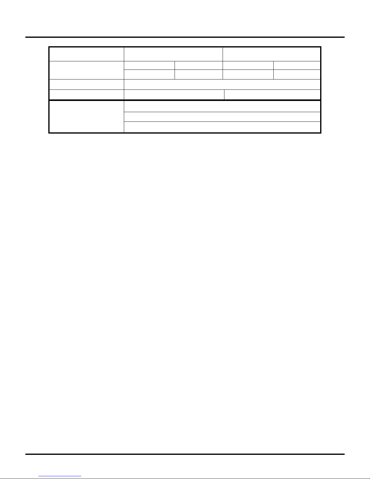
Gas Supply
Natural Gas
Propane
Pressure
Minimum
6.5 W.C.
Minimum
11.0 W.C.
Maximum
14.0 W.C.
Maximum
14.0 W.C.
Connection
½ female NPT
Manifold Pressure
6.0 W.C.
10 W.C.
Electrical
Requirements
(3 options)
120 V, 20 VA wired to junction box
24V, 20 VA
Millivolt pilot system
HEATER SPECIFICATIONS
Series S Page - 9 - March 4, 2014
Page 10
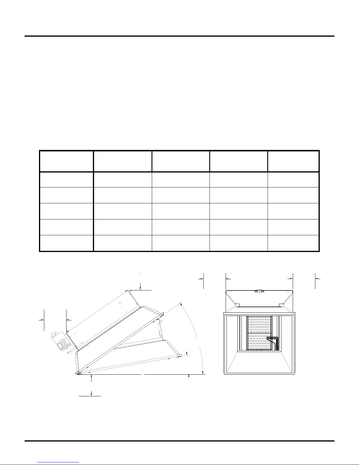
CLEARANCE TO COMBUSTIBLES
Model Number
Top
Sides
Rear
Below
S3
35 (89 cm)
28 (71 cm)
20 (51cm)
70 (178 cm)
S6
40 (102 cm)
35 (89 cm)
20 (51 cm)
80 (203 cm)
S9
50 (127 cm)
42 (107 cm)
28 (71 cm)
100 (254 cm)
S12
54 (137 cm)
46 (117 cm)
28 (71 cm)
110 (280 cm)
S16
60 (153 cm)
48 (122 cm)
34 (87 cm)
134 (341 cm)
BELOW
REAR
TOP
10° MIN.
35° MAX.
SIDE
SIDE
The stated clearance to combustibles represents a surface temperature of 90°F (50°C) above room
temperature. Building materials with low heat tolerance (such as plastics, vinyl siding, canvas, tri-ply,
etc…) maybe subject to degradation at lower temperatures. It is the installer’s responsibility to assure that
adjacent materials are protected from degradation.
WARNING
Clearances as marked on the heater body must be maintained from vehicles parked beneath. Signs should
be posted identifying any possible violation of the clearance distances from the heater in all vehicle areas.
Clearance to combustibles must be maintained according to the following chart. In storages areas, signs must
be posted to specify the maximum permissible stacking height.
Adequate clearance to sprinkler heads must be maintained.
Figure 2: Clearance to Combustibles Diagram
Series S Page - 10 - March 4, 2014
Page 11
INSTALLATION
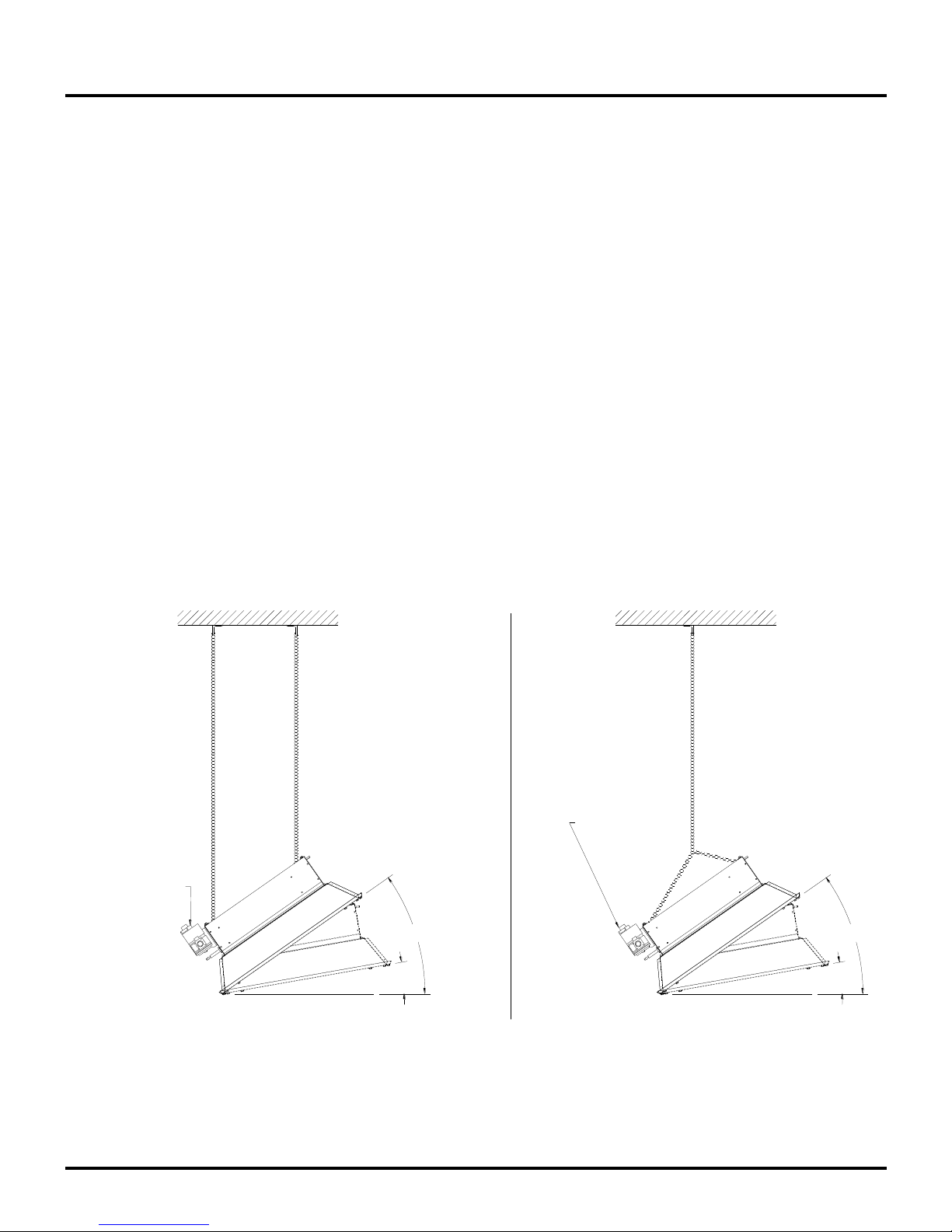
TYPICAL RIGID MOUNTING CONFIGURATION
GAS MANIFOLD TRAIN
MUST BE LOCATED
ON THE LOW SIDE
OF THE HEATER.
10° MIN.
35° MAX.
USE 3/8" DIA. THREADED ROD
FOR MOUNTING HEATER. AND/OR
WHERE DRAFT CONDITIONS MAY
BE EXPECTED.
TYPICAL CHAIN MOUNTING CONFIGURATION
GAS MANIFOLD TRAIN
MUST BE LOCATED
ON THE LOW SIDE
OF THE HEATER.
10° MIN.
35° MAX.
WHEN USING "S" HOOKS:
USE 3/16" DIA. WIRE, AND
CRIMP ALL "S" HOOKS CLOSED.
NOTES:
- OVERHEAD STRUCTURE AND FIELD CONNECTIONS MUST
BE ADEQUATE TO SUPPORT WEIGHT OF THE HEATER.
- MAIN GAS LINES AND ELECTRICAL LINES MUST NOT
CROSS OVER TOP OF HEATER.
Gas
Figure 3 illustrate typical rigid and chain mounting configurations for the Series S heaters; verify which
is permissible by local codes.
Heaters must be hung at an angle between 10° and 35°. Typically, at the walls they are at 35° facing
into the building. The gas manifold must always be at the lower side of the heater.
Minimum 3/16 diameter S hooks and No. 1/0 chain (200 lb./ 91 kg working load) is recommended.
Close S hooks after installation.
Never use a gas line as a hanging support and never locate gas or electric lines over the heaters.
Maintain clearance to combustibles.
Ensure that there is a plugged tap upstream of the heater or a fitting on the valve itself to verify
incoming pipeline pressure.
Do not leave the heater connected when pressure testing the pipeline. The high pressure will damage
the equipment.
Series S Page - 11 - March 4, 2014
Figure 3: Mounting Configurations
Page 12
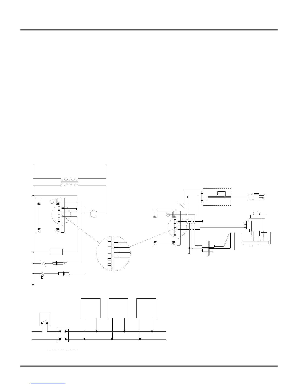
If any of the original wire as supplied with the
appliance must be replaced, it must be replaced
with wiring material having a temperature rating
of at least 105°C.
Si lun des câbles dorigine fournis avec cet
appareil dnit etre remplacé, le remplacer par
un câble convenant pour une température
nominale dau moins 105°C.
1 FLAME SENSE
2 TR, 24 VAC RETURN
3 GND, GROUND
4 MV, MAIN VALVE RETURN
6 TH, THERMOSTAT 24 VAC HOT
8 MV, MAIN VALVE HOT
HEATER
10
THERMOSTAT
230/24V
FLAME SENSOR
N
L1
HEATER HEATER
12
11
GAS VALVE
SPARK ELECTRODE
MV (MAIN VALVE HOT)
IGNITION MODULE
FLAME SENSE
TH (24V HOT)
MV (24V RTN)
GND (GROUND)
TR (24V RTN)
N (RTN)
THERMOSTAT
7
10
11
12
8
9
1
4
5
6
2
3
4
7
9
8
5
6
1
2
3
L1 (HOT)
JUNCTION BOX
FLAME SENSOR
SPARK ELECTRODE
GROUND ROD
FOR T'STAT WIRING
INTERCEPT BLUE WIRE
GROUND
9
IGNITION MODULE
11
12
10
MV (MAIN VALVE HOT)
TH (24V HOT)
MV (24V RTN)
GND (GROUND)
TR (24V RTN)
FLAME SENSE
3
5
4
7
8
6
2
1
GREEN
PINK
YELLOW/GREEN
BLUE
YELLOW
BROWN
TRANSFORMER
POWER CORD
GAS VALVE
MV
MV
Typical Wiring Layouts
* In some cases the 120/24 volt transformer can be positioned
prior to the thermostat. In this case, evaluate the contact
load across the thermostat contacts, as the load created by
the operating heaters may be too great. In that case a relay
should be used.
* When using a 24 volt system, be sure that the control
transformer being used has enough VA (volt amp) rating
for the heater control system being used. Example:
Operating five 24V model "S" heaters using one transformer,
each control or heater requires 20 VA. 5 units x 20VA = 100VA
transformer capacity minimum.
INSTALLATION
Electric
Figure 4 illustrates typical wiring arrangements for the Series S heater. Two options are available; 230V and 24V
supply. Up to six heaters may be operated from one thermostat. (Verify thermostat electrical capacity if non SRP
product is used.)
Ensure the heaters are properly grounded.
If mechanical exhaust is used in the building, it is typical to interconnect these in the heater circuit as
shown in Figure 4.
Perform all work in accordance with local codes or the National Electric Code ANSI/NFPA 70 or
Canadian Electrical Code CSA C22.1.
CONTROL DESCRIPTION
24 VOLTS—DIRECT SPARK IGNITION
100% SHUT OFF
APPLIES TO NATURAL GAS OR PROPANE GAS
Series S Page - 12 - March 4, 2014
Figure 4: Wiring Diagram
Page 13
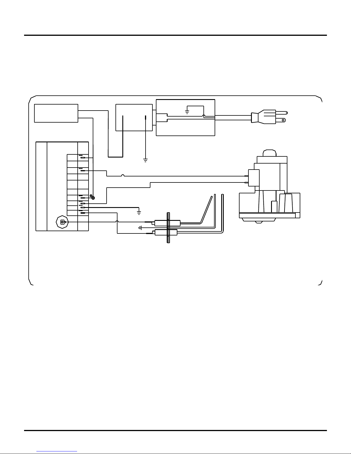
INSTALLATION
GREEN
FLAME SENSOR
GAS VALVE
SPARK ELECTRODE
PINK
GROUND ROD
MV
MV
POWER CORD
YELLOW
BROWN
JUNCTION BOX
TRANSFORMER
GREEN
BLUE
If any of the original wire as supplied with the
appliance must be replaced, it must be replaced
with wiring material having a temperature rating
of at least 105°C.
Si l'un des fils électriques original fournis avec
cet appareil doit etre remplacé, le remplace avec
un fil électrique fait de la température évalu ation
d'au moins 105°C.
SL003
S1
GND
V2
V1
HV
TH
24 V
BLUE
CNE MODULE
THERMOSTAT
24V
Series S Page - 13 - March 4, 2014
Page 14
VENTILATION / CONDENSATION
L1
N
HUMIDISTAT
L1
N
FAN #2
FAN
RELAY
FAN #1
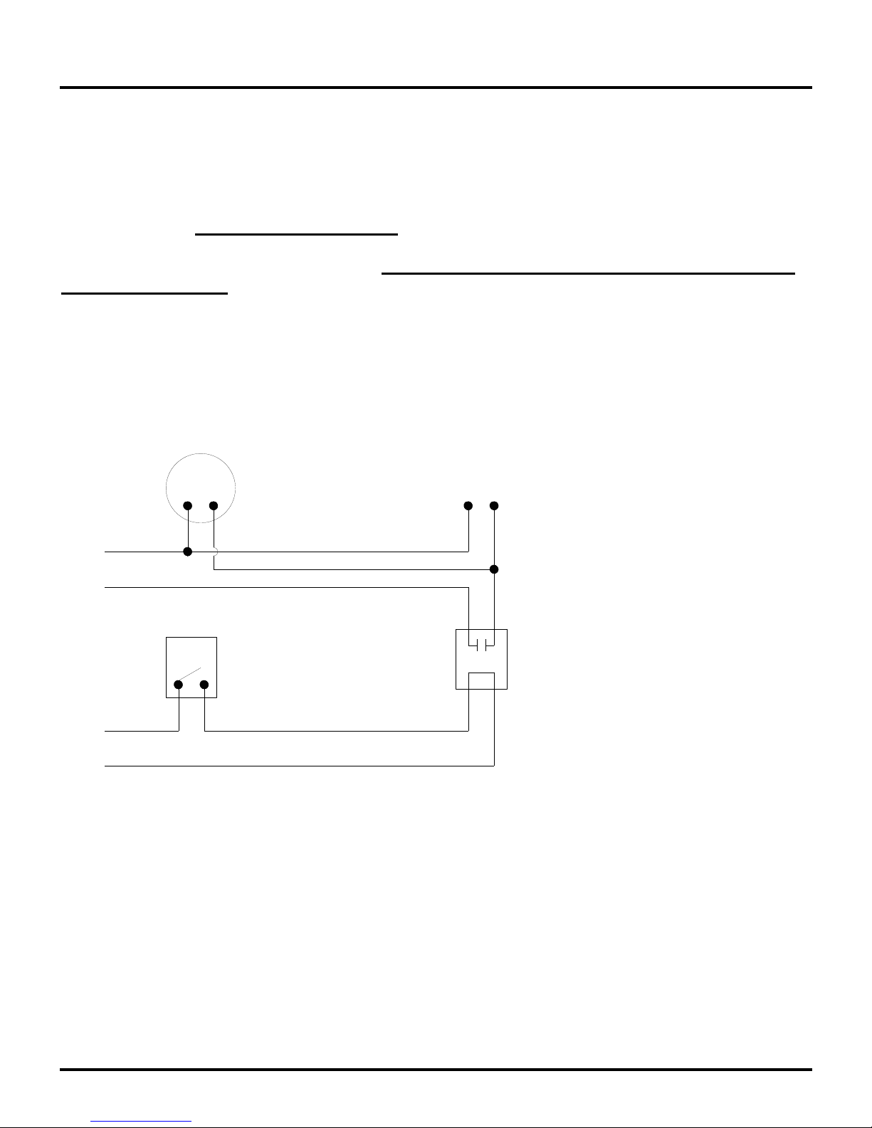
When using a humidistat to control exhaust
fans, wire the humidistat to cause the fan to
operate on humidity rise, NOT humidity fall.
Depending on fan horsepower, a relay may or
may not be needed.
Ventilation
Buildings using high intensity radiant heaters require ventilation. High Intensity type heaters are considered
un-vented gas fired appliances, requiring ventilation to supply combustion air and dilute/remove the products
of combustion.
Requirements for combustion air supply and dilution air vary by jurisdiction, building type and specific
installation details. See local codes for guidance. In general, where heaters are installed without direct
outside combustion air, fresh air ventilation must be provided to building space (3 cfm per 1000 BTU/Hr in
Canada, 4 cfm per 1000 BTU/Hr in the USA), Verify applicable local codes in the USA as requirements
change by jurisdiction.
Mechanical exhaust should be electrically interconnected with the heaters and should always be
installed in conjunction with inlet air openings. See “Block Diagram for Interconnecting
Fan/Humidistat” above for details.
Inlet air opening should be relatively small and distributed over the operating area of the heaters.
They must always be located below the level of the heaters. One square inch of net free inlet area per
1000 BTUH is recommended.
Condensation
The products of combustion for natural gas contain up to 1 liter of water per 100,000 BTU consumed. This
may add substantial amounts of moisture to the building air environment and may become a problem of
condensation on cold surfaces within the building. This is particularly true for poorly insulated metal roof
decks or structural steel framing.
To decrease condensation, increase mechanical ventilation.
Ensure that continuous waterproof barriers are used on the inside of all insulated surfaces.
Ensure that exhausters pull air from the entire space and across the condensing surface.
Humidistat controls may be integrated into the electrical control circuit of the heaters.
Series S Page - 14 - March 4, 2014
Figure 5: Block Diagram
Page 15

OPERATION / MAINTENENCE
Operation
Ensure the gas supply line has been purged.
Open all gas cocks to the heaters and electrically energize the system.
Follow the instructions on the heaters Lighting Instructions Label. Check to ensure that the thermostat starts
and shuts down the system.
Control Operating Sequence—Direct Spark Ignition
1. The thermostat calls for heat.
2. The combination gas valve opens and the spark igniter sparks in an attempt to light the fuel at the
face of the ceramic. The spark will continue for 15 seconds
3. Once flame is established (prior to complete steady-state conditions) the flame sensor signals the
module and sparking stops. If the burner does not light in 15 seconds, the system will lockout, i.e.
electric energy to the gas valve and electronic module is cut. The lighting sequence may be reset
by an interruption of the electric power supply.
4. Once operating, the heater will continue to do so until the thermostat is satisfied; shutting the gas
valve.
Annual Maintenance
1. Close the fuel gas valve and de-energize electrical power to the heater.
2. With an air hose regulated to no more than 15 psig blow away accumulated dust. Blow across the
face of the ceramic tiles, not directly at them. Blow into each venturi for about one minute.
3. Verify that there are no cracked tiles.
4. Review the wiring for any loose connections.
Series S Page - 15 - March 4, 2014
Page 16

Symptom
Possible Cause
Corrective Acton
Heaters will not turn off
Defective thermostat
Stuck solenoid valve
Repair or replace
Repair or replace
Gas Odor
Loose pipe connection
Verify all connections are sealed by
using an appropriate leak test
Burning of gas/air mixture inside
venturi (flashback)
Cracks between or across ceramic grids
Excessive drafts
Replace burner head assembly
Shield or relocate heater
Heaters Cycles on/off
Excessive drafts
Flame sense not grounded
Low gas pressure
Shield or relocate heater
Verify wiring and correct
Verify and correct
Low surface temperature on
ceramic surface
Dirty or plugged ceramics
Low inlet gas pressure
Misaligned manifold/orifice
Insufficient gas supply
See cleaning maintenance
Verify and correct
Replace manifold
Verify capacity of fuel supply lines
No spark, no ignition
No power to control module
Control module defective
No power to spark electrode
No equipment ground
Heater sparks but will not light
No gas supply
Defective gas valve solenoid
Defective electronic control
Check shut off valve and combination
gas valve
Heater lights but ‘locks out’ after
about 10 seconds
Poor ground
Reversed polarity on electric supply
Sense electrode not sensing flame
Defective electronic control
Check continuity of sense electrode
Verify and/or replace
Verify and correct/replace
Verify and correct/replace
Verify and correct/replace
TROUBLESHOOTING
Series S Page - 16 - March 4, 2014
Page 17
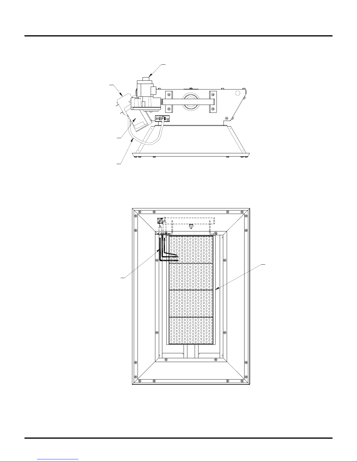
PARTS
ELECTRODE ASSEMBLY
(P/N SE001)
IGNITION WIRE
(P/N CE006)
IGNITION MODULE
(P/N CE109)
TRANSFORMER
(P/N SE004)
BURNER HEAD
ASSEMBLY
(P/N SG009)
GAS VALVE
(P/N SG003 - NAT GAS)
(P/N SG004 - LPG)
XXXX
XXX-XXX
Series S Page - 17 - March 4, 2014
Figure 6: Replacement Parts
Page 18

SERIES S INFRARED HEATERS
WARRANTY
The Manufacturer warrants to the original owner that the product will be free of defects in
material and workmanship. For the Series S, the warranty for all components except for the
ceramic burner head assembly is limited to 24 months from the date of installation. The ceramic
burner head assembly shall be warranted for an additional eight years for units which are proven
to the satisfaction of the manufacturer to be inoperative due to defects in material or workmanship.
The Manufacturer’s obligation under this warranty is limited to repair or replacement, F.O.B. its
facility, of the defective part. In no event shall the manufacturer be liable for incidental expense or
consequential damages of any kind.
This warranty does not cover any shipping, installation or other labor costs incurred in the repair
or re-placement of the product. No materials will be accepted for return without authorization.
This warranty will not apply if in the judgment of the Manufacturer the equipment has been
improperly in-stalled, unreasonably used, damaged, or modified.
This warranty will not apply to damage to the product when used in corrosive atmospheres and in
particular atmospheres containing halogenated hydrocarbons. No person is authorized to assume
for the Manufacturer any other warranty, obligation or liability.
THE REMEDIES PROVIDED FOR IN THE ABOVE EXPRESS WARRANTIES ARE THE
SOLE AND EXCLUSIVE REMEDIES. NO OTHER EXPRESS OR IMPLIED WARRANTIES
ARE MADE INCLUDING, BUT NOT LIMITED TO, ANY IMPLIED WARRANTY OF
MERCHANTABILITY OR FITNESS FOR A PARTICULAR USE OR PURPOSE.
Address questions to your local distributor
Heater Series
Installed rate
Serial Number
Installed date
:_________________________
:__________________Btu/hr
:_________________________
:_________________________
Series S Page - 18 - March 4, 2014
WARRANTY
 Loading...