

Page 1
Premier VS Infrared Heating System
Installation, Operation and Maintenance Instructions
FOR YOUR SAFETY
If you smell gas:
1. Open windows
2. Don’t touch electrical switches
3. Extinguish any open flame
4. Immediately call your gas supplier
FOR YOUR SAFETY
Do not store or use gasoline or other
flammable vapors and liquids in the
vicinity of this or any other appliance.
Read and thoroughly understand these instructions before attempting any installation.
CONSIGNES DE SEURITE
Si vous sentez une odeur de gaz:
1. Ouvrez les fenêtres
2. Ne touchez pas aux interrupteurs
électriques
3. Éteignez toute flamme nue
4. Contactez immédiatement votre
fournisseur de gaz
CONSIGNES DE SEURITE
Il est interdit d’utiliser des liquides
inflammables ou dégageant des vapeurs
inflammables, a proximités de tout
appareil fonctionnent au gaz.
Installer
Owner
Retain this manual for reference.
Improper installation, adjustment, alteration, service or maintenance can cause injury, death or
property damage. Read the installation, operating and maintenance instructions thoroughly before
installing or servicing this equipment.
Une installation, un réglage, une modification, une réparation ou un entretien incorrect peut entraîner
des dommages matériels, des blessures ou la mort. Lisez attentivement les instructions d’installation,
de fonctionnement et d’entretien avant de procéder à l’installation ou à l’entretien de cet équipement.
563 Barton Street, Stoney Creek, Ontario L8E 5S1
WARNING
AVERTISSEMENT
www.superiorradiant.com
06/14 LT013
Page 2
CAUTION: FIRE OR EXPLOSION HAZARD
Maintain clearance to combustible constructions as further specified in this manual.
Failure to do so could result in a serious fire hazard. Heaters should not be located in
hazardous atmospheres containing flammable vapors or combustible dusts. Signs should
be provided in storage areas specifying maximum safe stacking height and safe parking
locations for vehicles of various heights.
CAUTION: MECHANICAL HAZARD
This equipment expands and contracts with each operating cycle. The gas connection,
suspension hardware and the installation itself must safely allow this movement. Failure to
do so could result in serious fire or explosion hazard.
CAUTION: FIRE OR EXPLOSION
This heater is equipped with an automatic ignition device. Do not attempt to light the
burner by hand. Failure to comply could result in a serious fire and personal injury hazard.
CAUTION: MECHANICAL HAZARD
Do not use high pressure (above ½ psi [3.5 kPa]) to test the gas supply system with the
burners connected. Failure to comply could result in damage to the burner and its contr ol
components requiring replacement.
CAUTION: SERVICE LIFE RISK
Do not install equipment in atmospheres containing halogenated hydr ocarbons or other
corrosive chemicals. Failure to comply may lead to premature equipment failure and
invalidation of the warranty. Additionally, it is recommended that the equipment be
installed with a slope downward and away from the burner of ¼” in 10 ft
allow drainage of start-up condensate.
(7 mm per 3 m) to
Page 3

TABLE OF CONTENTS
INTRODUCTION .................................................................................................................................................... 4
Operating Principle ....................................................................................................................................... 4
APPLICABLE CODES ........................................................................................................................................... 5
General Installation and Gas Codes .............................................................................................................. 5
Aircraft Hangar Installation .......................................................................................................................... 5
Public Garage Installation ............................................................................................................................. 5
Parking Structures ......................................................................................................................................... 5
Gas Supply Lines .......................................................................................................................................... 5
Electrical ....................................................................................................................................................... 5
Venting .......................................................................................................................................................... 5
EQUIPMENT SPECIFICATIONS ........................................................................................................................ 6
System Layout Types .................................................................................................................................... 6
Basic Components ........................................................................................................................................ 8
Burners ........................................................................................................................................................ 10
Vacuum Pump A ......................................................................................................................................... 16
Vacuum Pump B ......................................................................................................................................... 17
CLEARANCE TO COMBUSTIBLES ................................................................................................................. 18
INSTALLATION ................................................................................................................................................... 20
Preparation .................................................................................................................................................. 20
Assembly Overview Notes ......................................................................................................................... 22
Part 1 - Radiant Line System ..................................................................................................................... 23
A‐RadiantLineTubes..............................................................................................................................23
B ‐TailpipeTubes.....................................................................................................................................28
C ‐Burners................................................................................................................................................29
D‐Reflectors............................................................................................................................................33
E ‐OptionalShieldEquipment.................................................................................................................37
F ‐Deco‐GrilleOption..............................................................................................................................41
Part 2 - Vacuum Pump & Venting ............................................................................................................. 43
A‐VacuumPumpMounting....................................................................................................................44
B ‐VentilationConnections......................................................................................................................48
C ‐AdditionalPumpConnections&Equipment.......................................................................................49
Part 3 - Optional Combustion Air Supply .................................................................................................. 50
A‐CombustionAirSupplyDuctConnections..........................................................................................50
Part 4 - Gas Supply System ....................................................................................................................... 51
A‐FlexibleGasConnectorLine................................................................................................................52
Part 5 - Electrical Connections................................................................................................................... 53
A‐Burners................................................................................................................................................54
B ‐FreshAirBlowerInterlock...................................................................................................................55
C ‐SystemWiringConnections................................................................................................................57
COMMISSIONING ............................................................................................................................................... 63
Part 1 - Installation Checklist ..................................................................................................................... 63
Part 2 - Initial System Power Test ............................................................................................................. 64
Part 3 - Balancing the System Vacuum ..................................................................................................... 65
OPERATION ......................................................................................................................................................... 67
MAINTENANCE & TROUBLE-SHOOTING ................................................................................................... 68
PARTS .................................................................................................................................................................... 71
WARRANTY .......................................................................................................................................................... 74
Page 4

INTRODUCTION
Superior Radiant Products is a company in the infrared heating industry founded on the principles of product
quality and consumer commitment.
Quality commitment is evidenced by superior design, a regard for design detail and an upgrade of materials
wherever justifiable.
Customer commitment is apparent through our ready responses to market demands and a never ending training
and service support program for and through our distributor network.
The Premier VS Vacuum System is the culmination of decades of infrared expertise and commitment to quality
products. The VS system is easy to install and maintain, offers flexibility of design which is unmatched in the
industry and provides economical and trouble free operation.
Important
These instructions, the layout drawing, local codes and ordinances, and applicable standards such as
apply to gas piping and electrical wiring comprise the basic information needed to complete the
installation, and must be thoroughly understood along with general building codes before proceeding.
Only personnel who have been trained and understand all applicable codes should undertake the
installation. SRP Representatives are Factory Certified in the service and application of this
equipment and can be called on for helpful suggestions about installation.
Operating Principle
The PREMIER VS System operates on the following basic principles:
The Burner Unit can provide Rates from 120,000 to 250,000 BTU/hr.
Burner Models are specially engineered & built for the individual ‘Positions’ they are installed
in along each Branch.
Burner Rate (BTU/hr) is determined by the Vacuum Setting of the Branch. Rates can be
adjusted by changing the Vacuum Settings at the Branch End Vent.
Systems may be operated in ONE of TWO modes:
o Single Rate: Entire system operates at ONE fixed rate using Manual Dampers.
o Modulating Rate: The use of Motorized Dampers allows the System to adjust the overall
Heat Output during operation to meet building demand by automatically changing the
Vacuum Settings of the Branches in the System.
Premier VS Infrared Heating System Page 4 June 04, 2014
Page 5

APPLICABLE CODES
Installations must comply with local building codes, or in their absence, the latest edition of the national
regulations and procedures listed below:
General Installation and Gas Codes
Heaters must be installed only for use with the type of gas appearing on the rating plate, and the installation
must conform to the National Fuel Gas Code, ANSI Z223.1 (NFPA 54) in the US and the Natural Gas and
Propane Installation Code, CAN/CGA B 149.1 & B149.2 in Canada.
This heater must maybe approved for either indoor or outdoor installation. Not for use in residential
dwellings, refer to rating plate.
Aircraft Hangar Installation
Installation in aircraft hangars must conform to the Standard for Aircraft Hangars, ANSI/NFPA 409 in the US
and CAN/CGA B149.1 & B149.2 in Canada.
Public Garage Installation
Installation in public garages must conform to the Standard for Parking Structures, NFPA-88A or Standard
for Repair Garages, NFPA 88B, in the US and CAN/CGA B149.1 & B149.2 in Canada.
Parking Structures
Technical requirements are outlined in the Standard for Parking Structures, ANSI/NFPA 88a, in the US and
CAN/CGA B149.1 & B149.2 in Canada.
Gas Supply Lines
Gas supply pipe sizing must be in accordance with the National Fuel Gas Code, ANSI Z223.1 (NFPA 54) in
the US and the Natural Gas and Propane Installation Code, CAN/CGA B149.1 & B149.2 in Canada.
A 1/8” inch NPT plugged tap must be installed in the gas line connection immediately upstream
of the burner farthest from the gas supply meter to allow checking of system gas pressure.
Electrical
All heaters must be electrically grounded in accordance with the National Electric Code, ANSI/NFPA 70 in
the US, and the Canadian Electric Code, CSA C22.1 in Canada, and must comply with all local requirements.
Venting
Refer to the National Fuel Gas Code, ANSI Z223.1 (NFPA 54) in the US and the Natural Gas and Propane
Installation Code, CAN/CGA B149.1 and B149.2 in Canada for proper location, sizing and installation of
vents as well as information on termination clearance requirements when penetrating combustible walls for
venting purposes.
Premier VS Infrared Heating System Page 5 June 04, 2014
Page 6
EQUIPMENT SPECIFICATIONS
System Layout Types
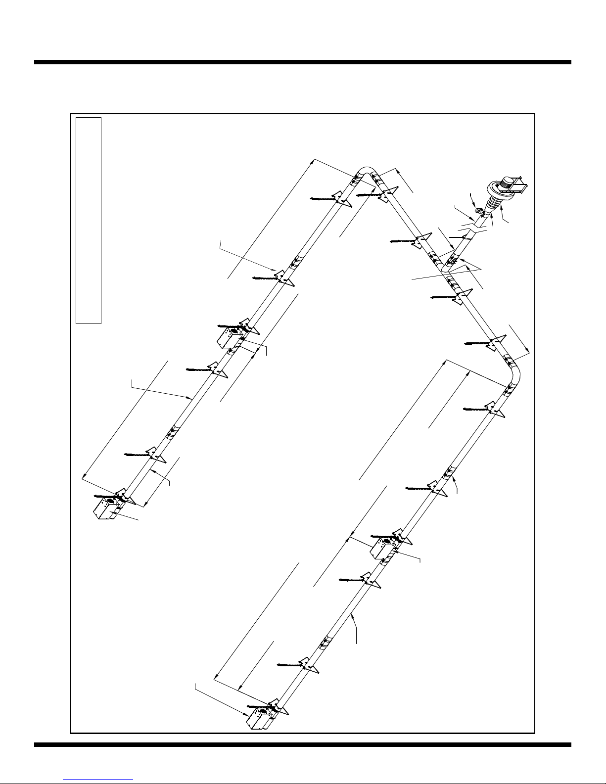
Figure 1: Symmetric System Overview
Vacuum Switch
Common Tailpipe
Reducer
e
p
Flexible Boot
i
p
l
i
a
T
Shown WITHOUT Reflectors for Tube Clarity
Radiant Tube
e
p
i
p
l
i
a
Reflector Hanger
"
B
"
h
c
n
a
r
B
t
n
a
i
d
a
R
e
n
i
L
t
n
a
i
d
a
R
g
n
i
l
p
u
o
T
C
r
e
p
m
a
D
Burner #1
Combustion Tube
L
t
n
a
i
d
a
R
Burner #1
e
n
i
Burner #2
d
a
R
e
n
i
L
t
n
a
i
d
a
"
A
"
h
c
n
a
r
B
t
n
a
i
d
a
R
e
n
i
L
t
n
a
i
R
Coupling
Burner #2
Premier VS Infrared Heating System Page 6 June 04, 2014
Radiant Tube
Page 7
EQUIPMENT SPECIFICATIONS
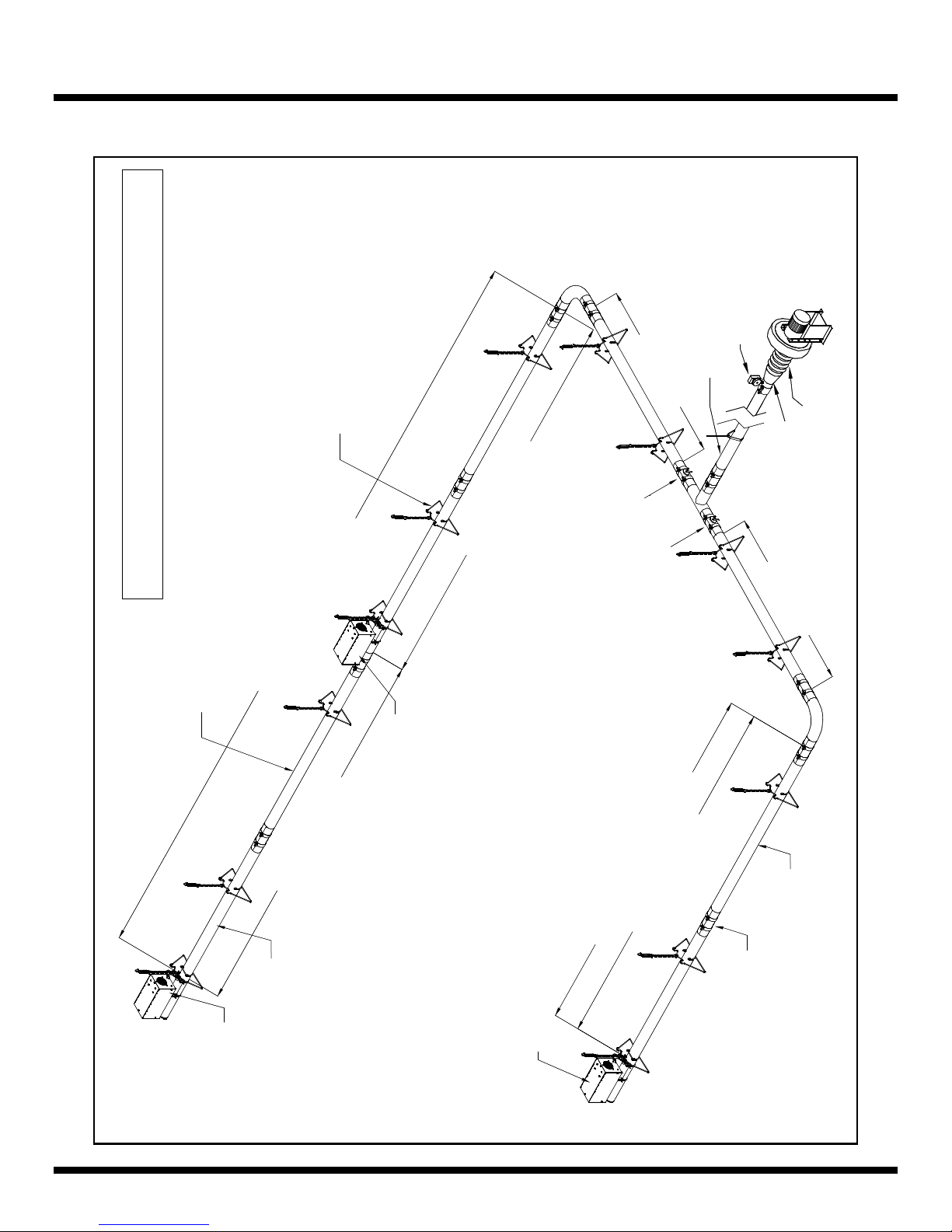
Figure 2: Non Symmetric System Overview
e
p
i
p
l
i
a
T
Vacuum Switch
Common Tailpipe
Reflector Hanger
e
n
i
L
t
n
a
i
"
B
"
h
Shown WITHOUT Reflectors for Tube Clarity
d
a
R
c
n
a
r
B
t
n
a
i
R
d
a
s
g
n
i
l
p
u
o
C
r
e
p
m
a
D
Reducer
Flexible Boot
e
p
i
p
l
i
a
T
Radiant Tube
t
n
a
i
d
a
R
Burner #1
Premier VS Infrared Heating System Page 7 June 04, 2014
Combustion Tube
B
R
"
A
"
h
e
c
n
n
i
a
L
r
t
n
a
i
d
a
e
n
i
L
Burner #2
R
t
n
a
i
d
a
Radiant Tube
Burner #1
Coupling
Page 8
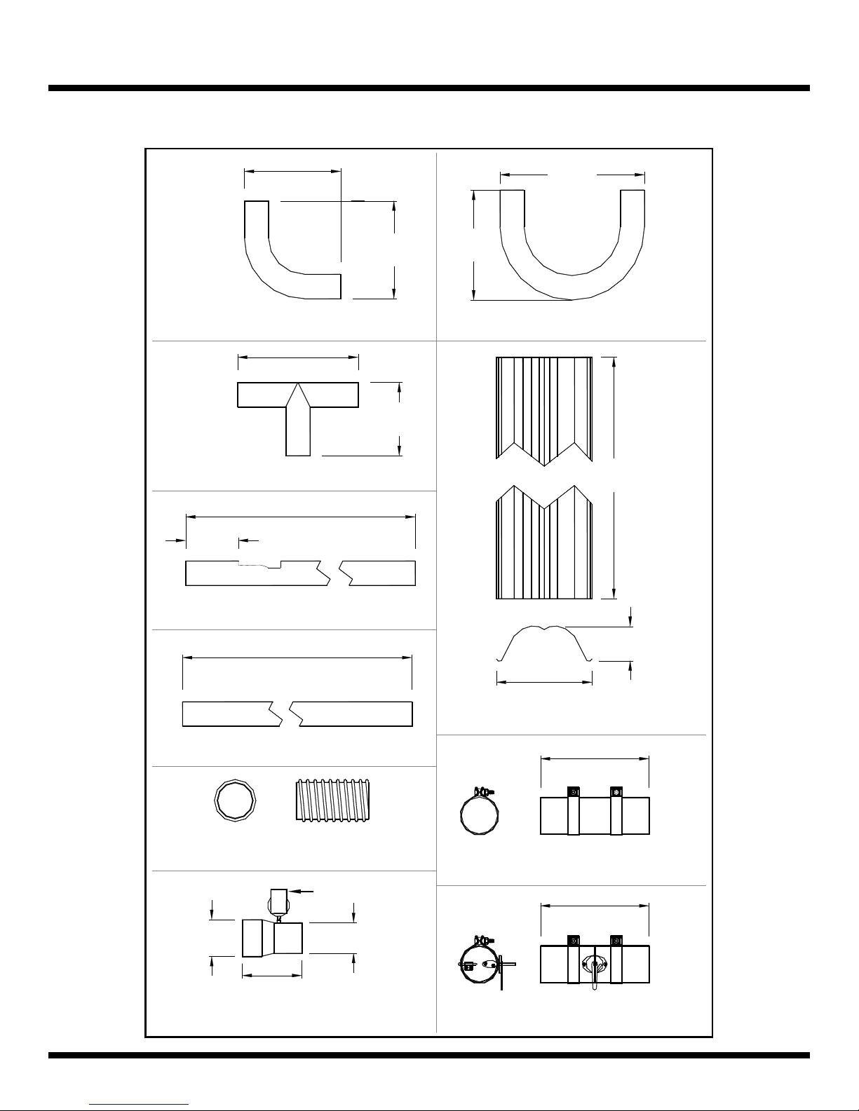
EQUIPMENT SPECIFICATIONS
Basic Components
Tube Elbow, 4" (10.2cm) Ø
36"
(91.4cm)
Figure 3: Common Component Dimensions
16"
(40.6 cm)
16"
(40.6 cm)
20"
(50.8 cm)
12"
(30.5 cm)
Tube Tee, 4" (10.2cm) Ø
120"
(305 cm)
18"
(45.7 cm)
Tube U Bend, 4" (10.2cm) Ø
24"
(61 cm)
124"
(315 cm)
Combustion Tubes, 4" (10.2cm) Ø
120"
(305 cm)
Tubes, 4" (10.2cm) Ø & 5" (12.7cm) Ø
Flexible Boot
4" (10.2cm) Ø Or 6" (15.2cm) Ø
Vacuum Switch
Ø 6"
(15.2cm)
7.4"
(18.8 cm)
Ø 4" (10.2cm)
or 5" (12.7cm)
Reducer w/Vacuum Switch
6" (15.2 cm)
16"
(40.6 cm)
Standard Reflector
12"
(30.5 cm)
Tube Coupling
4" (10.2cm) Ø or 5" (12.7cm) Ø
12"
(30.5 cm)
Damper Coupling
4" (10.2cm) Ø or 5" (12.7cm) Ø
Premier VS Infrared Heating System Page 8 June 04, 2014
Page 9
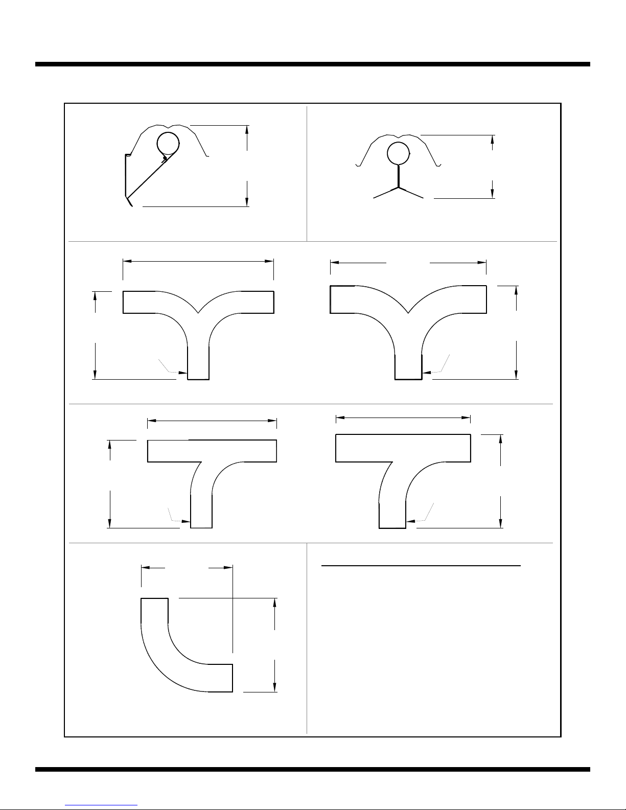
EQUIPMENT SPECIFICATIONS
Figure 4: Specialty Component Dimensions
16"
(40.6 cm)
Side Reflector
4" Ø
(10.2cm)
28"
(71 cm)
24"
(61 cm)
15.5"
(39.4 cm)
Double Swept Tee
Bottom Shield
29"
(74 cm)
(12.7cm)
25"
(63.5 cm)
(25.4 cm)
5" Ø
10"
17"
(43 cm)
16"
(40.6 cm)
4" Ø
(10.2cm)
17"
(43 cm)
5" Ø
(12.7cm)
Single Swept Tee
Additional Components Available:
17"
(43 cm)
Stainless Steel (S/S) Components
Reflector Kit, Mitered 90°
Fresh Air Inlet Hood
17"
(43 cm)
- - -
Tubing
Coated Tube & Tubing Components
45° Elbow, 4" Ø
Cross Fitting, Square, 4" or 5" Ø
Cross Fitting, Double Swept, 5" Ø
Tube Elbow, 5" (12.7cm) Ø
Hanger Strap, 4" or 5" Ø (tailpipe)
*A List of Parts & Part Numbers can be found in the PARTS Section at the end of this Manual.
Premier VS Infrared Heating System Page 9 June 04, 2014
Page 10
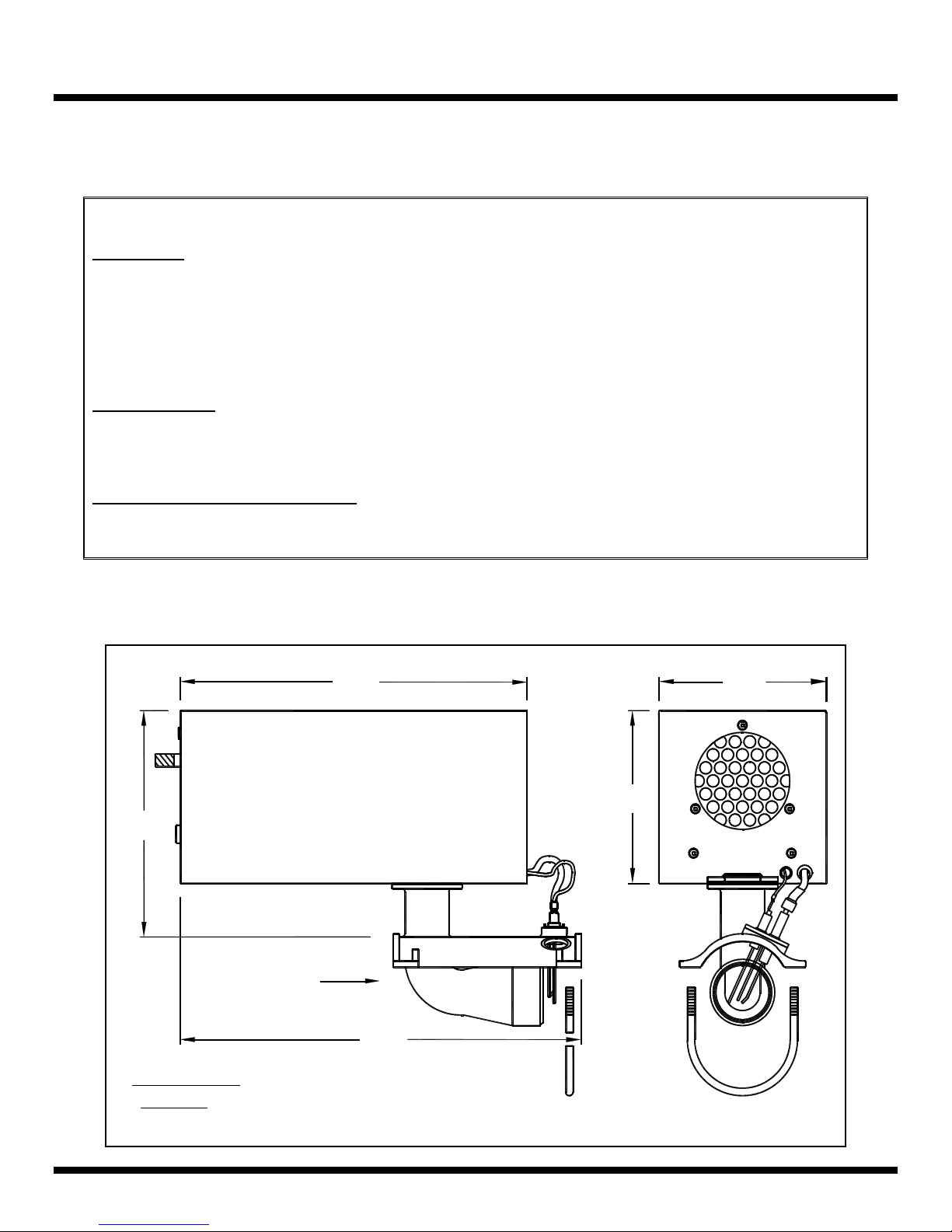
EQUIPMENT SPECIFICATIONS
Burners
General Burner Specifications
Gas Supply
Natural Gas: Minimum 5.0” W.C. Propane Gas: Minimum 11.0” W.C.
Maximum 14.0” W.C Maximum 14.0” W.C.
Manifold Pressure: Natural Gas: 0” W.C. Inlet Connection: ½” NPT male
Propane Gas: 0” W.C.
Electric Supply
120 VAC, 60 Hz, 0.2 Amp: 36” (0.9 m) cord connecter with grounded 3-prong plug.
Flue and Outside Air Connection
4” type C duct for flue adaptor and outside air (optional) provided at the heater.
Figure 5: Burner Dimensions
14.75
(37.5)
7.18
(18.2)
9.48
(24.1)
7.11
(18.1)
Air Flow
Direction
Dimensions: Inches (centimeters)
Weight: 25 lbs (11.4kg)
Premier VS Infrared Heating System Page 10 June 04, 2014
17.06
(43.3)
Page 11
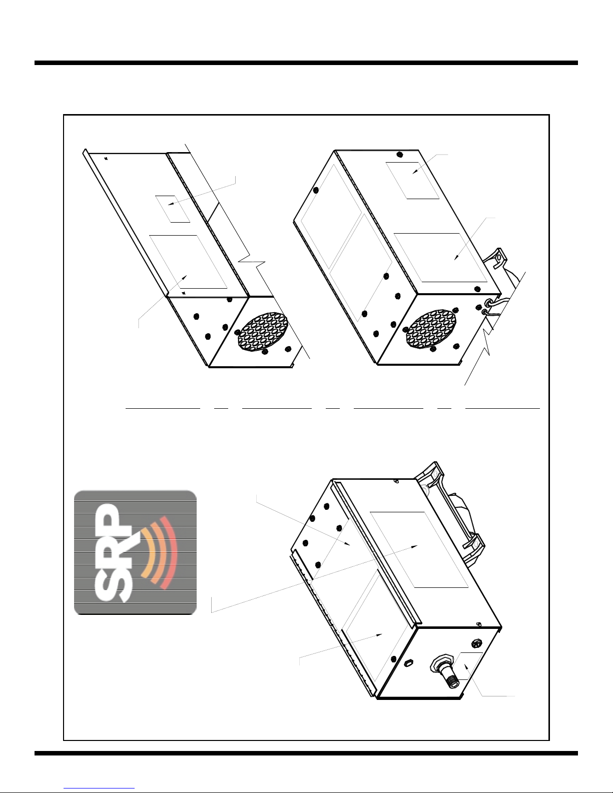
EQUIPMENT SPECIFICATIONS
)
L
E
N
A
P
f
o
E
D
I
S
N
I
(
Figure 6 : Locations of Burner Labels /Stickers
Venting
VL005
Label
N
E
P
O
Warning
Diagram
UL007
Clearance
Label
VL002
Wiring
Diagram
VL008
Manufacturer's
Logo (SRP)
Burner
Rating Plate
VL007
Premier VS Infrared Heating System Page 11 June 04, 2014
VL001
Burner
Rate Chart
CL034
Gas Connection Label
Page 12
EQUIPMENT SPECIFICATIONS
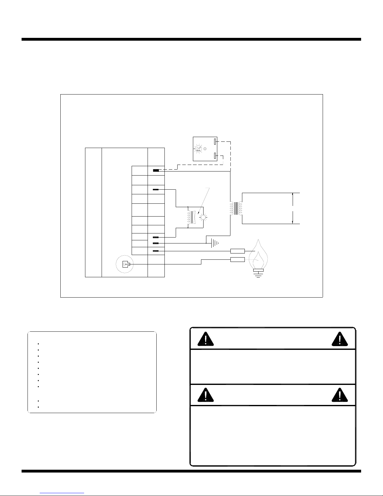
Details of all Burner Labels / Stickers: (7)
Wiring Diagram - VL008
WIRING DIAGRAM
FENWALL DSI MODEL VS
TH
V1
V2
GND
S1
HV
Optional
Delay-on-make
Timer
BLUE
BROWN
YELLOW
GREEN
PINK
NOTE: If any of the original wire as supplied with
the appliance must be replaced, it must be replaced
with wiring material having a rating of at
Gas
Valve
RUN
LAMP
YELLOW
RED
24V
least 105°C
RED
SENSOR
IGNITER
L1
TRANSFORMER
NEUTRAL
BURNER
120V
VL008
08/09
Venting Label - VL005
1. SRP Part # for venting materials
wall thimble (4") . . . . . . . . . . . . . . .
wall thimble (6") . . . . . . . . . . . . . . .
vent terminal (4") . . . . . . . . . . . . . .
vent terminal (6") . . . . . . . . . . . . . .
C vent / aluminized tube (4") . . . . .
C vent / galvanized tube (6") . . . . .
Vibration Boot Package (4") . . . . . .
Vibration Boot Package (6") . . . . . .
2. Vent length from vacuum pump
minimum 2 ft.
maximum 50 ft.
Premier VS Infrared Heating System Page 12 June 04, 2014
CS006
CS033
CT011
CT044
CT001
CT059
VS010
VS048
VL005
02/10
Warning Diagram - UL007
Improper installation, adjustment, alteration, service or
maintenance can cause property damage, injury or death.
Read the Installation, Operating and Maintenance Instructions
thoroughly before installing or servicing this equipment.
WARNING
AVERTISSEMENT
For use with natural gas or propane. A conversion kit as
supplied by the manufacture, shall be used to convert this
heater to the alternate fuel. Installation shall be by qualified
personnel only.
Pour utilization avec gaz naturel ou propane. Pour changer d un
combustible a lautre, vous été requisz de prendre une trousse
fournie par le fabricant. Linstallation doit etre fait par des
personnes qualifiees seulement.
`
UL007
Page 13

12"
For US use only
For Canada use only
150 MBTU. Gas connector sold separate from heater.
Gas Connection Label - CL034
3" Max.
Displacement
Heater Movement End View
WARNING: Connector Must Be Installed As Shown Above.
1
" x 24" or 36" SS ; or
2
1
" x 30" rubber ; or
2
(on a YELLOW Background)
3
" x 24" SS for burners over 150 MBTU
4
3
" x 30" rubber for burners over
4
90°
45°
EQUIPMENT SPECIFICATIONS
*For more Gas Connection details refer to Part 4 Gas Supply System on page 51.
45°
CL034
VS Burner Rates – VL017
Premier VS - Chart of Burner Rates
Important: This burner is a variable input appliance.
See chart below to determine appliance burn rate.
Natural Gas requires a No.
LP Gas requires No.
A conversion kit as supplied by the manufacturer shall be used to
covert to the alternate fuel.
A flow plate appropriate to the position of the burner in the system
MUST be installed (see Manufacturer's Instructions).
Positions are identified in ascending order from the start end of the system.
Note: An end vent vacuum intermediate to those shown will result
in rates intermediate and proportional to those indicated.
End Vent
Vacuum
(in. wc)
4.5
3.6
3.0
2.0
1.7
Burner Position 1
Flow Plate No. 1
Rate (BTUH)
250,000
225,000
200,000
175,000
150,000
S drill size orifice.
K drill size orifice.
Burner Position 2
Flow Plate No. 2
Rate (BTUH)
165,000
130,000
120,000
Burner Position 3
Flow Plate No. 3
Rate (BTUH)
130,000
120,000
Premier VS Infrared Heating System Page 13 June 04, 2014
Superior Radiant Products Ltd.
Stoney Creek, ON
VL017
02/10
Page 14
EQUIPMENT SPECIFICATIONS
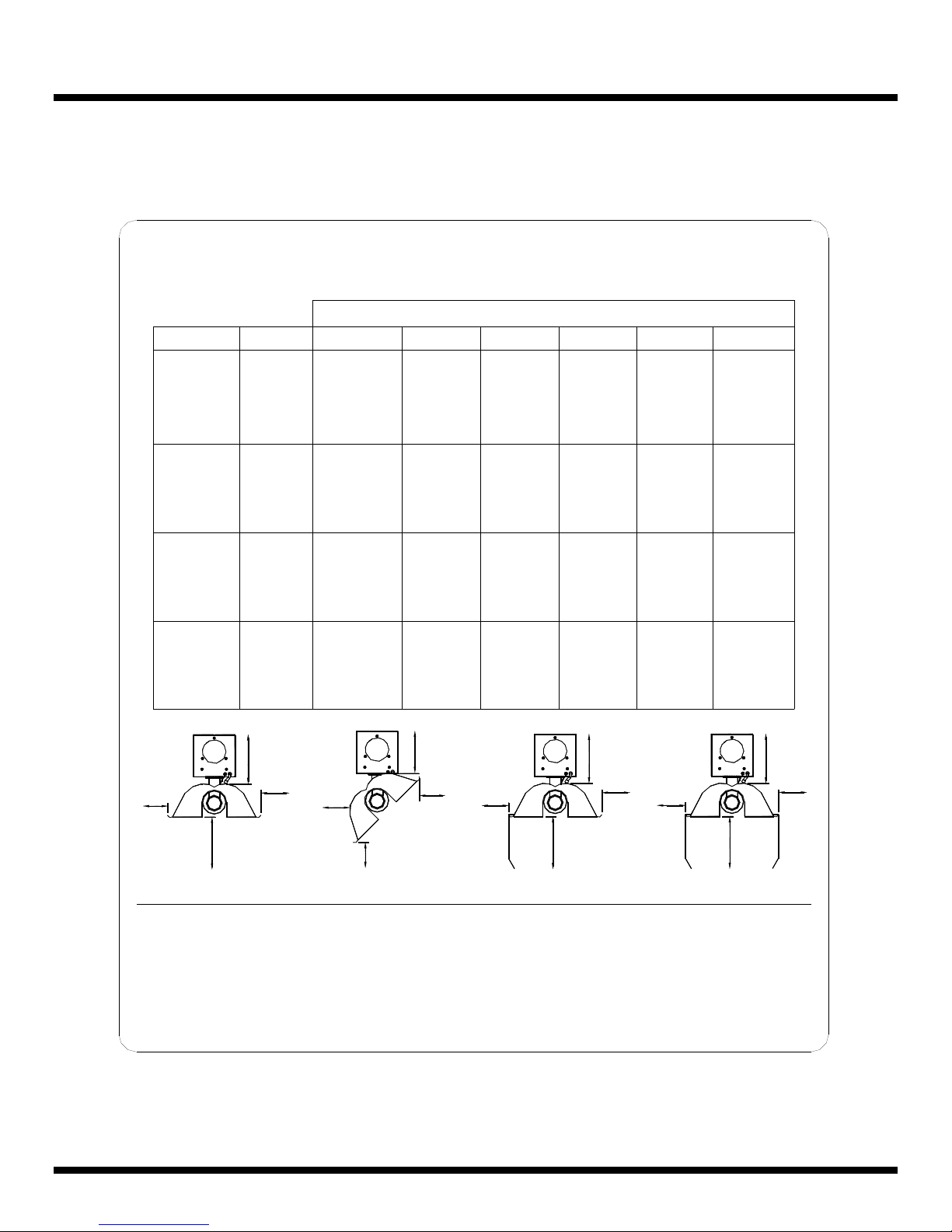
Clearance Label – VL018
MINIMUM CLEARANCE TO COMBUSTIBLE MATERIALS
for space heating applications (inches)
DIM.
120
BURNER RATE 1,000 BTUH
150
175
200
225
250
B
FIG. 1
FIG. 2
FIG. 3
FIG. 4
A
B
C
D
A
B
C
D
A
B
C
D
A
C
D
A
D
4
30
60
30
4
4
66
59
4
4
73
49
4
74
21
B
4
36
73
36
6
4
71
64
4
4
77
52
4
2321B 3432
79
23
A
D
4
40
75
40
6
4
74
67
6
6
80
54
6
26
82
26
B
44
80
44
78
72
84
56
29
86
29
6
6
4
6
6
6
A
D
6
46
83
46
6
4
81
75
6
6
87
58
6
89
32
B
6
50
85
50
6
4
83
77
6
6
89
60
6
92
34
A
D
C
FIG. 1
NOTES:
Fig. 1 clearances also apply with use of approved decorative grill.
Use of approved bottom shield reduces C by up to 25% EXCEPT BURNER RATE
250,000 BTUH.
Downstream 25 ft. from burner: B, C, D can be reduced by 50% for burner rates up to
150,000 BTUH and by 40% for burner rates 150,000 to 250,000 BTUH.
(See Manual for Complete Details).
Premier VS Infrared Heating System Page 14 June 04, 2014
C
FIG. 2
C
FIG. 3
C
FIG. 4
VL018
02/10
Page 15
EQUIPMENT SPECIFICATIONS
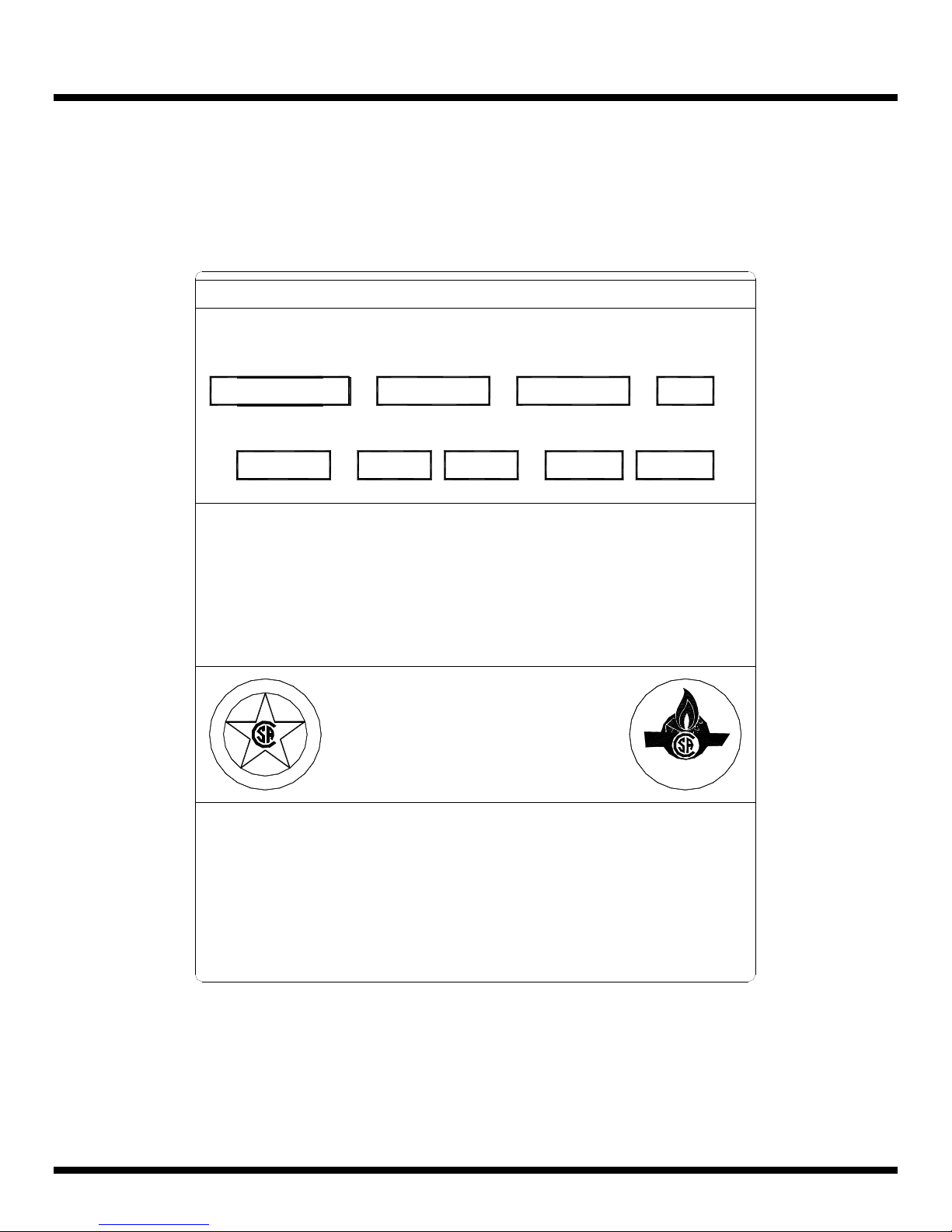
Burner Rating Plate - VL007
INFRARED HEATER / RADIATEUR INFRA-ROUGE
U.S. Patent # 5,842,854
MODEL NO.
No. modele
SUPERIOR RADIANT PRODUCTS LTD.
STONEY CREEK, ON CANADA
0-4500'
SERIAL NO.
No. de serie
INPUT BTUH
See Chart
Debit calorifique
GAS
Gaz
ELECTRICAL RATING
115V 60Hz 1A
Class electrique
SUITABLE FOR INSTALLATION
SUITABLE FOR INSTALLATION IN AIRCRAFT HANGARS PER ANSI 409 & PUBLIC GARAGES PER NFPA 88A
HEATER MAY BE INSTALLED IN VARIABLE CONFIGURATION IN HORIZONTAL POSITION ONLY
Peut-etr Installe En Configuration Variable Mais En Position Horizontal Seulement
FOR NON-RESIDENTIAL SPACE HEATING AND BROODER USE
HEATER MAY BE VENTED OR UNVENTED
Peut Etre Ventile Ou Non
I
S
G
E
N
D
MANIFOLD PRESSURE
0" W.C. NAT
Press a l'orifice
MIN. SUPPLY PRESSURE
5" W.C. NAT
Press d'alimentation
INDOORS/Interieur
Pour Chauffage Non-residentielle Et Elevage Des Poules
REFLECTOR MAY BE INSTALLED AT 45°
Reflecteur Peut Etre Installe A 45°
CERTIFIED
CERTIFIE
'
CAN1-2.20 M85 (R2006) IAS-U.S. Req. 8-94
ANSI Z83.20-2008 / CSA 2.34-2008
C
E
R
T
LIGHTING INSTRUCTIONS
1. ENSURE ALL MAIN SUPPLIES ARE OFF.
2. SET THERMOSTAT BELOW AMBIENT TEMPERATURE.
3. TURN MAIN GAS VALVE ON.
4. TURN ON ELECTRICAL CURRENT.
5. SET THERMOSTAT TO DESIRED TEMPERATURE.
SHUT DOWN INSTRUCTIONS
1. TURN DOWN THERMOSTAT.
2.TURN OFF ELECTRIC POWER.
3.TURN OFF MAIN GAS VALVE.
4. WAIT 5 MINUTES BEFORE ATTEMPTING TO RE-LIGHT.
D
E
I
®
F
I
CAN/CSA C22.2 No. 3-M1988 (R2004)
CGA 2.17-M91 (R2009)
INSTRUCTION DE MIS EN MARCHE
1. ASSUREZ QUE TOUTES ALIMENTATION EST FERMER.
2. REGLEZ LE THERMOSTAT AU DESSUE DE LA
TEMPERATURE AMBIENT.
3. OUVEREZ LA VANNE PRINCIPAL DE GAZ.
4. OUVEREZ LE COURANT ELECTRIQUE.
5. REGLEZ LE THERMOSTAT A LA TEMPERATURE
DESIRER.
INSTRUCTION DE FERMETURE
1. DESCENDEZ LE THERMOSTAT EN DESSOUS DE LA
TEMPERATURE AMBIENT.
2. COUPEZ LE COURANT ELECTRIQUE.
3. FERMEZ LA VANNE PRINCIPALE DE GAZ.
4. ATTENDEZ 5 MINUTES AVANT UNE ESSAI DE
REALUMAGE.
CERTIFIED
®
VL007
11/09
Premier VS Infrared Heating System Page 15 June 04, 2014
Page 16
EQUIPMENT SPECIFICATIONS
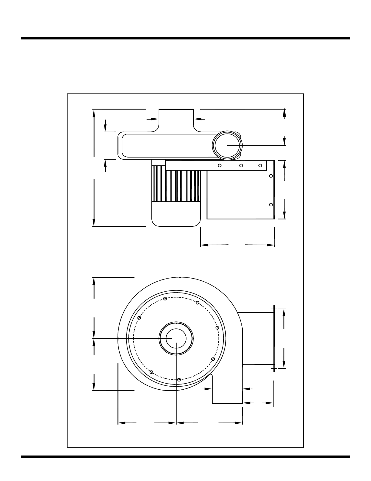
Vacuum Pump A
Electric Supply: 115/230 VAC, 60Hz, 1 PH, 0.75 HP
Tube Connection: 6” dia. Inlet & 4” dia. Outlet
Figure 7: Vacuum Pump A - Available in RH or LH Style
3.75
(9.5)
16.06
(40.8)
6.0 Ø
(15.2)
5.00
(12.7)
Dimensions: Inches (centimeters)
Weight: 100 lb (45.5kg)
(Including connecting pieces)
8.38
(21.3)
7.13
(18.1)
9.81
(24.9)
8.00
8.12
(20.6)
(20.3)
Premier VS Infrared Heating System Page 16 June 04, 2014
7.73
(19.6)
8.78
(22.3)
4.0 Ø
(10.2)
4.25 (10.8)
Page 17
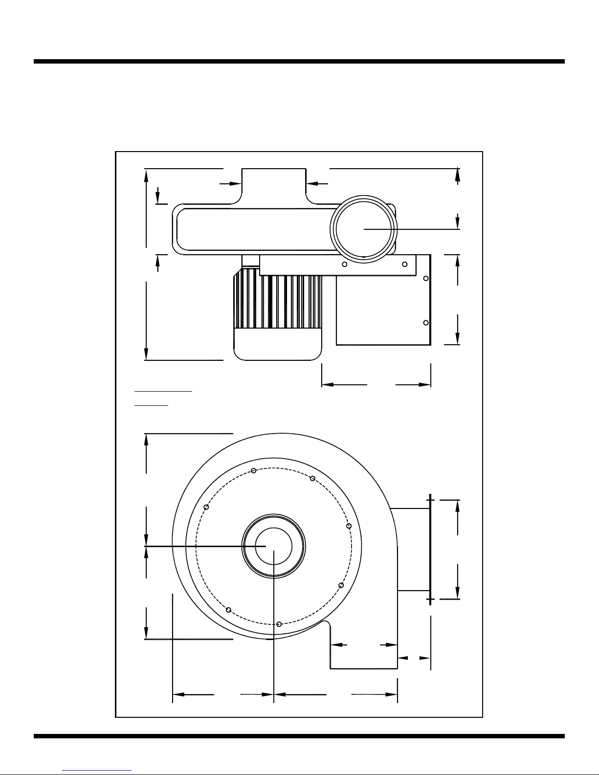
Vacuum Pump B
EQUIPMENT SPECIFICATIONS
Electric Supply: 208/230/460 VAC, 60Hz, 3 PH, 1.5 HP
Tube Connection: 6” dia. Inlet & 6” dia. Outlet
Figure 8: Vacuum Pump B - Available in RH or LH Style
6.0 Ø
(15.2)
4.49
(11.4)
17.00
(43.2)
5.38
(13.7)
Dimensions: Inches (centimeters)
Weight: 115 lbs (52.3kg)
(Including connecting pieces)
10.01
(25.4)
9.73
(24.7)
8.00
(20.3)
8.79
(22.3)
8.24
(20.9)
Premier VS Infrared Heating System Page 17 June 04, 2014
9.03
(22.9)
11.02
(28.0)
6.0 Ø
(7.5)
(15.2)
2.97
Page 18
CLEARANCE TO COMBUSTIBLES
A general clearance of 18” (0.5 m) in every direction is required around each Burner, Vacuum Pump, and
End Vent Cap air supply (at the far end of each Radiant Branch) to ensure adequate air flow in and around the
Heating System.
In addition to this it is very important to observe the minimum clearance to combustibles at all times to
avoid any possibility of property damage or personal injury.
Clearances as marked on the heater body must be maintained from vehicles parked beneath. Signs should be
posted identifying any possible violation of the clearance distances from the heater in all vehicle areas.
Maximum allowable stacking height in storage areas should be identified with signs or appropriate markings
adjacent to the thermostat or in a conspicuous location.
Combustible materials are considered to be wood, compressed paper, plant fibres, plastic, Plexiglas or other
materials capable of being ignited and burned. Such materials shall be considered combustible even though
flame-proofed, fire-retardant treated or plastered.
The stated clearance to combustibles represents a surface temperature of 90°F (50°C) above room temperature.
Building materials with low heat tolerance (such as plastics, vinyl siding, canvas, tri-ply, etc…) may be
subject to degradation at lower temperatures. It is the installer’s responsibility to assure that adjacent
materials are protected from degradation.
Table A lists the minimum clearance to combustible materials for various installation configurations. Note that
standard clearances also apply to installation above T-bar ceilings and above decorative grills. Additional
clearance may be required for glass, painted surfaces and other materials which may be damaged by radiant or
convective heat.
Note 1:
Bottom Shields are approved for all Burner sizes except the 250,000 BTU/hr model. The
“below” clearance (dimension C in Table A) may be reduced by 25% when an approved
Bottom Shield is used.
Note 2:
Reduced clearances downstream from the Burner are approved for all configurations.
Dimensions “B”, “C”, and “D” in Table A can be reduced for locations 25 ft (7.6 m) or
more downstream from a burner, before the next burner:
- For burner sizes up to 150,000 BTU/hr; maximum reduction 50%
- For burner sizes 155,000 to 250,000 BTU/hr; maximum reduction 40%
Premier VS Infrared Heating System Page 18 June 04, 2014
Page 19
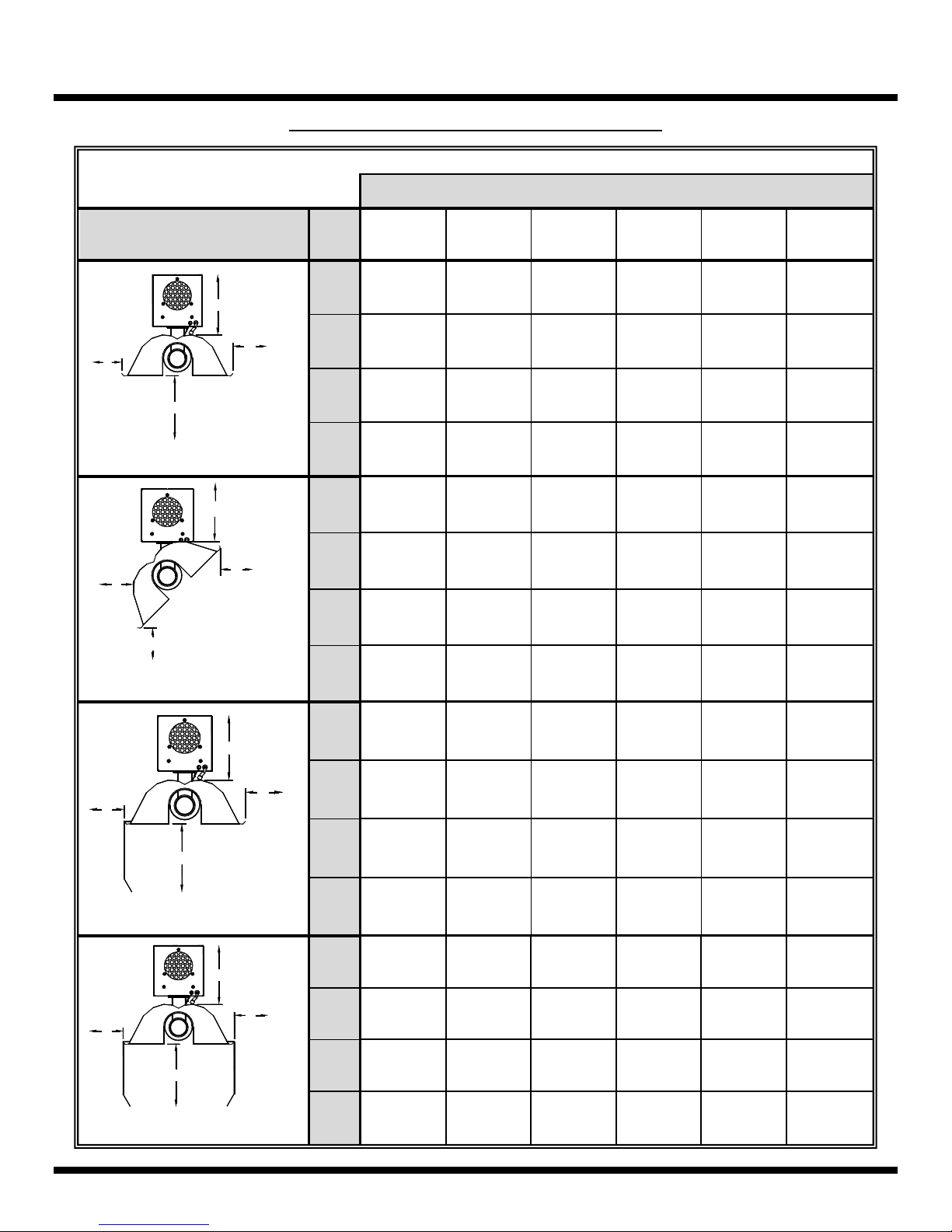
CLEARANCE TO COMBUSTIBLES
Table A: Required Clearance to Combustibles
*Clearance to combustibles for non- r eflectored fittings is 18” (0.5 m).
Dimensions: Inches ( cm)
Reflector
Configurations
A
D
B
C
Horizontal
A
D
B
C
45° Reflector Tilt
Burner Rate in Thousanda of BTU/hr [MBH]
Dim 120 150 175 200 225 250
A
444666
(10.2) (10.2) (10.2) (15.3) (15.3) (15.3)
B
30 36 40 44 46 50
(76.2) (91.4) (102) (112) (117) (127)
C
60 73 75 80 83 85
(153) (186) (191) (204) (211) (216)
D
30 36 40 44 46 50
(76.2) (91.4) (102) (112) (117) (127)
A
466666
(10.2) (15.3) (15.3) (15.3) (15.3) (15.3)
B
444444
(10.2) (10.2) (10.2) (10.2) (10.2) (10.2)
C
66 71 74 78 81 83
(168) (181) (188) (199) (206) (211)
D
59 64 67 72 75 77
(150) (163) (170) (183) (191) (196)
A
D
B
C
One Side Reflector
A
D
B
C
Two Side Reflectors
A
B
C
D
A
B
C
D
446666
(10.2) (10.2) (15.3) (15.3) (15.3) (15.3)
446666
(10.2) (10.2) (15.3) (15.3) (15.3) (15.3)
73 77 80 84 87 89
(186) (196) (204) (214) (221) (226)
49 52 54 56 58 60
(125) (133) (138) (143) (148) (153)
446666
(10.2) (10.2) (15.3) (15.3) (15.3) (15.3)
21 23 26 29 32 34
(53.3) (58.4) (66.0) (73.7) (81.3) (86.4)
74 79 82 86 89 92
(188) (201) (209) (219) (226) (234)
21 23 26 29 32 34
(53.3) (58.4) (66.0) (73.7) (81.3) (86.4)
Premier VS Infrared Heating System Page 19 June 04, 2014
Page 20
INSTALLATION
Preparation
Most vacuum system designs are laid out on a clean blank sheet of paper. Unfortunately, typical construction
does not permit this unimpeded access and therefore some planning and preparation early in the project will
save much time and effort later on.
Start by reviewing the installation procedure. Examine where the equipment will be installed and how it will be
supported. Please pay special attention to any objects that might be in the way or in close proximity to the
heating system. Refer to Table A (Clearance to Combustibles) to ensure a safe distance between the heating
system and any combustible materials.
Acquaint yourself with the standard components referred to in this manual. Many of these components are
shown in detail in Figure 3. They are also shown in general assembly form in Figure 1 and Figure 2 to illustrate
where the components fit in a typical symmetrical system and a non-symmetrical system. (These Figures are
found in the Equipment Specifications section.)
If possible, lay the entire system out on the floor prior to installation. This will help identify any potential
problems with the installation as well as any discrepancy in component quantity. Ensure that all Burners are
those specified for the planned system in both output and gas type.
*DO NOT TRIM / CUT ANY Combustion Tube, adjust the System to fit around the Combustion Tubes.
Layout Limits
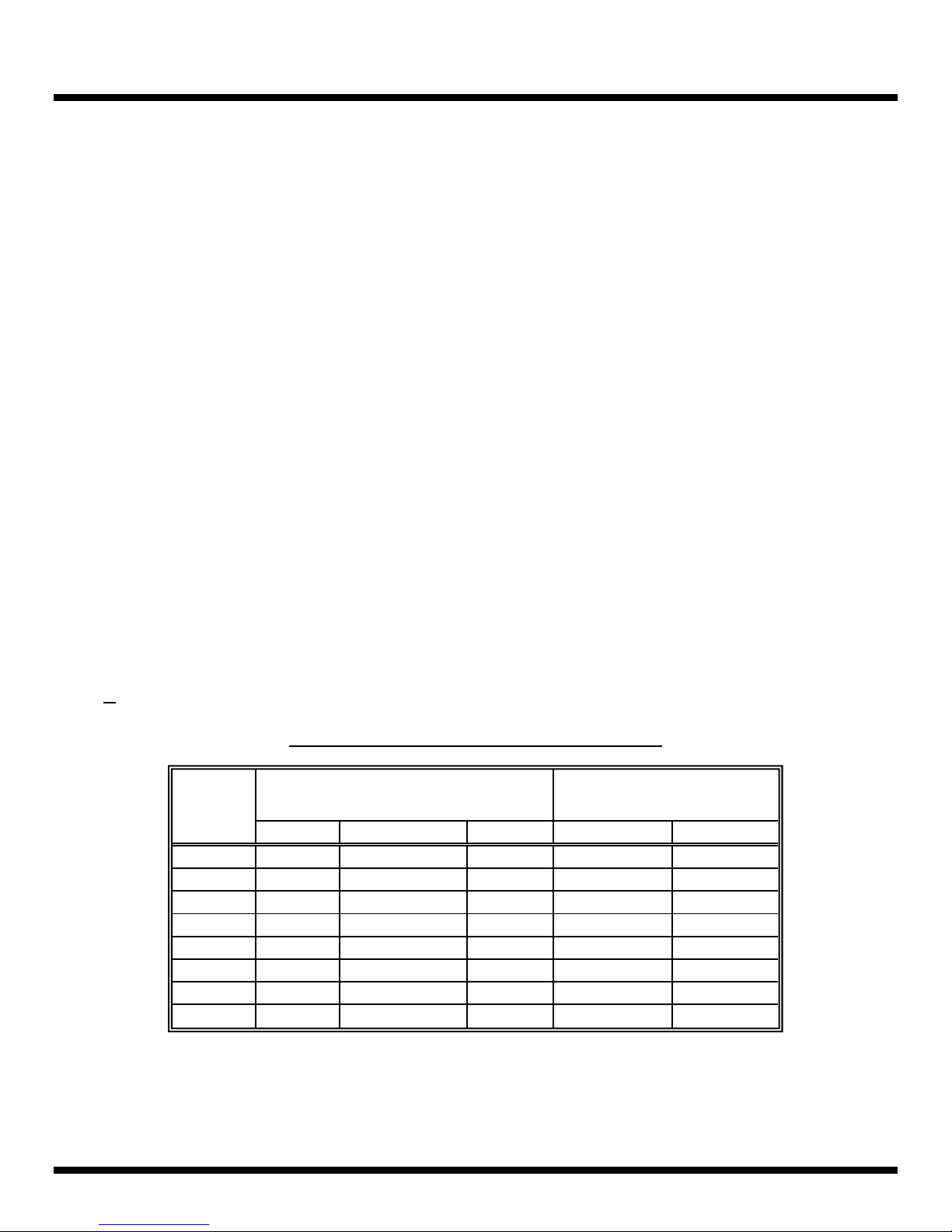
Ensure that the System Layout meets the limits required in Table B and
Table C for the Burner Rate you intend the System to function at.
Table B : Radiant Tube System Layout Limits
Burne r
Rating
[BTU/hr]
120000 30(9.2) 40(12.2) 45(13.7) 3(0.9) 15(4.6)
130000 35(10.7) 40(12.2) 55(16.8) 3(0.9) 20(6.1)
150000 40(12.2) 50( 15. 3) 60(18.3) 3(0.9) 20(6.1)
165000 45(13.7) 50(15.3) 65(19.8) 3(0.9) 20(6.1)
175000 45(13.7) 50(15.3) 65(19.8) 3(0.9) 20(6.1)
200000 50(15.3) 60(18.3) 70(21.4) 3(0.9) 25(7.7)
225000 50(15.3) 60(18.3) 70(21.4) 3(0.9) 25(7.7)
250
000 55(16.8) 70(21.4) 75(22.9) 3(0.9) 25(7.7)
*When minimum Radiant Tube lengths are used, minimum tailpipe length must be increased by 50%
(DistancebetweenBurners)[ft(m)]
Minimum Recommended Maximum BeforeBurner AfterBurner
RadiantTube Lengths
MinimumDistancetoElbow
[ft(m)]
Premier VS Infrared Heating System Page 20 June 04, 2014
Page 21
INSTALLATION
Table C: Tailpipe Lengths Required for Various Branch Layouts
Numberof
Burnersin
Radiant
Branch
1
2
3
1
2
3
1
2
1
1
Burne rInputRateateachPosition
[MBTU/hr]
No.1No.2No.3
TotalOutput
forBranch
[MBTU/hr]
150 ‐‐150 20(6.1)
150 120 ‐ 270 30(9.2)
150 120 120 390 30(9.2)
175 ‐‐175 20(6.1)
175 130 ‐ 305 30(9.2)
175 130 130 435 30(9.2)
200 ‐‐200 20(6.1)
200 165 ‐ 365 30(9.2)
225 ‐‐225 20(6.1)
250 ‐‐250 20(6.1)
Exceptions:
1)WhenminimumRadiantTubelengthsareused,
minimumtailpipelengthmustbeincre asedby50%
2)IfusingCommonTailpiperefertothefollowi ngtodetermine
theMinimumCommonTailpipelengthrequired:
1‐AddupusualrecommendedlengthsofTailpipe(fromdata inthisTable)
2‐SubtractthelengthofanyT ailpipewhichwillNOTbe Common
3‐Ifresultis>40'
OR3‐
Ifresultis≤40'remaining,multiplyby0.75forMinimumCommonTailpipeLength
remaining,multiplyby0.6forMinimumCommonTailpipeLength
3)Whenusing5"ØTailpipe,theRequiredTailpipeLengthsmayber educedby25%
Minimum
Tailpipefor
Branch
[ft(m)]
Premier VS Infrared Heating System Page 21 June 04, 2014
Page 22

INSTALLATION
Assembly Overview Notes
Generally there is no unique sequence for installation of the Premier VS system. A review of the job site will
often indicate a logical installation order. However, it is typical to start at the end of the branch with the furthest
Burner location and continue that Branch downstream towards the Vacuum Pump, then begin again with the
next Branch. Generally, 10 ft (3 m) increments of Tube and Reflector can be used until one reaches the
Common Tailpipe areas or Vacuum Pump connections. The general order of material in this manual is
recommended for low-hassle installation purposes.
The Installation of the Entire System potentially consists of 5 individual Parts, one Part for each major
component / system;
1- Radiant Line System, (Heat Exchangers)
2- Vacuum Pumps & Ventilation Systems,
3- Optional Combustion Air Supply System,
4- Gas Supply System, and
5- Electrical System(s)
Directions for the installation of each component / system are therefore found in the respective sections
along with general information and safety notes as required
Premier VS Infrared Heating System Page 22 June 04, 2014
Page 23

INSTALLATION – Part 1
Part 1 - Radiant Line System
For the purpose of this section the term “Radiant Line System” will refer only to the main heat exchanging
components: Tubes, Burners, Reflectors, Tailpipes and attached Optional pieces. These must be hung from
ceiling supports and form the main Radiant Lines & Branches of the Heat Exchanger System.
Installation of the Radiant Line System has been divided into 6 main parts as follows:
Radiant Line Tubes
Tailpipe Tubes
Burners
Reflectors
Option Shield Equipment
Deco-Grille Option
The order they are listed in is recommended for ease of installation and allows for adjustments to be made
easily if required. Other orders of installation are possible; please note that there are certain components which,
once installed, will make it more difficult to install others. Thoroughly read through the following installation
directions for details on individual components.
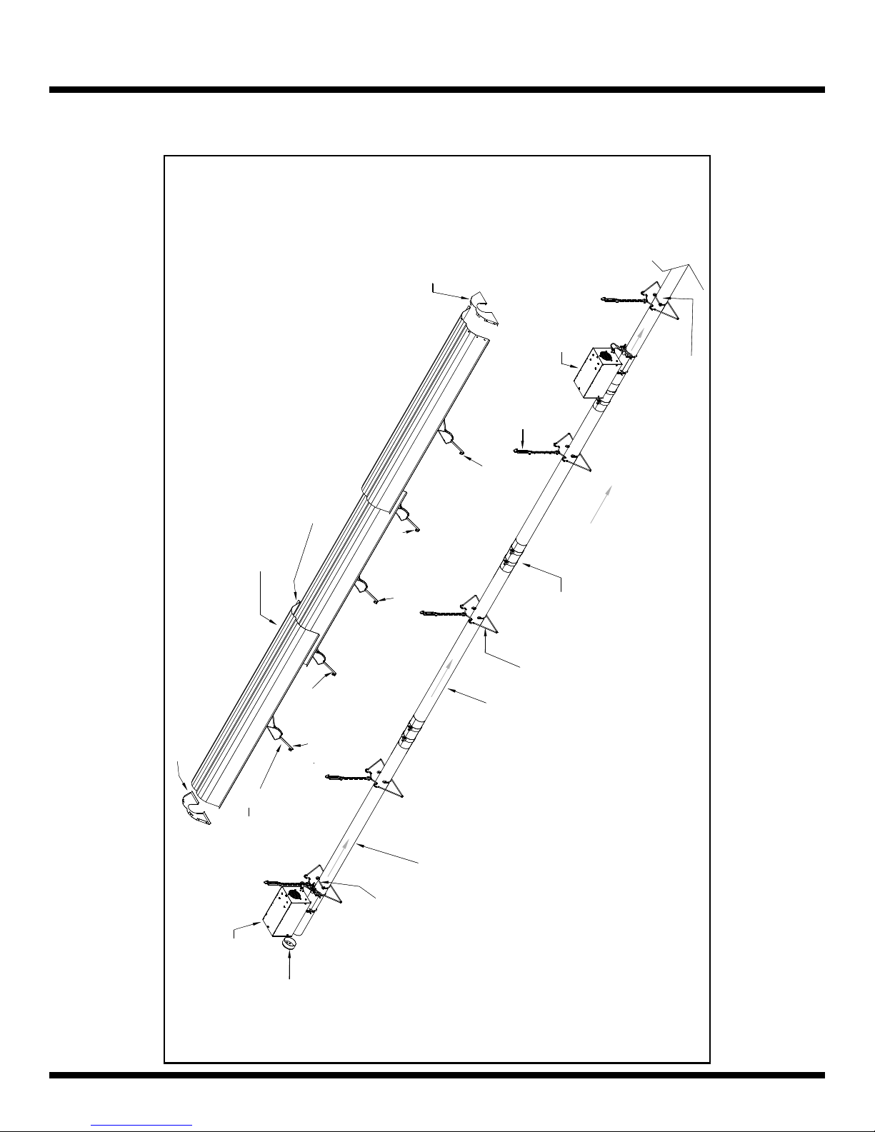
Figure 9 illustrates the relationship of many of the various components of the Radiant Line System and will be a
useful reference at many times during the installation.
NOTE: The Premier VS System does not typically require the use of Baffles, if Baffles are desired please
consult with the Manufacturer (SRP) prior to installation.
A - Radiant Line Tubes
All Combustion Tubes are heat-treated aluminized steel tubes. On Burners that are to be fired at
150,000 BTU/hr or more, the next 10 ft (3 m) Tube section is to be heat-treated aluminized as
well. The remaining Radiant Tube length can be either hot rolled or heat-treated aluminized
depending on the system design.
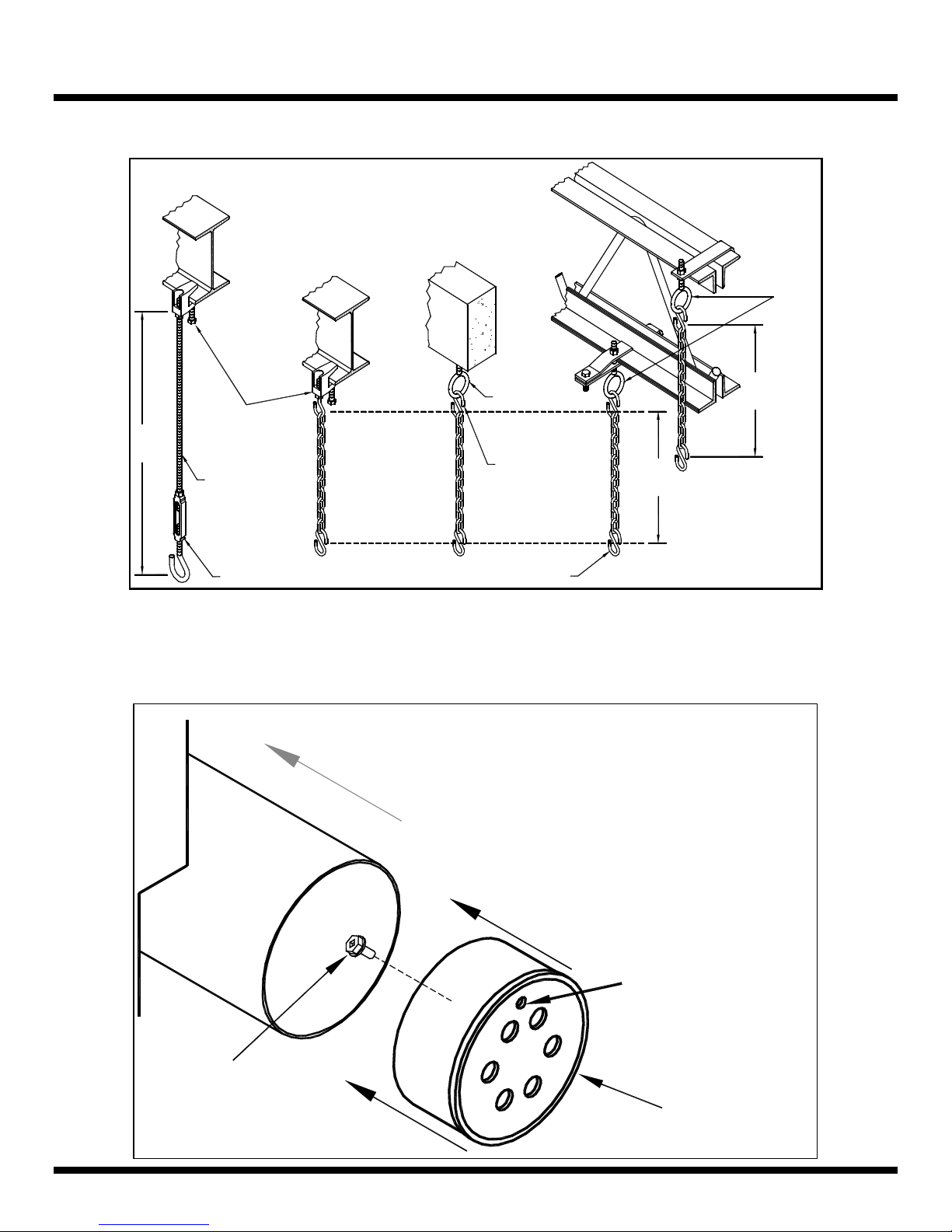
1. Locate hanging chain at predetermined points in the structure using methods as shown in Figure 10. The
first 2 hanging points are approximately 7.5 ft (2.3 m) apart to fully support each end of the first Tube.
Thereafter spacing of 10 ft (3 m) is acceptable, i.e. one hanging point per Tube. Ensure that Reflector
Hangers located on a Combustion Tube will be within 8” (20 cm) of the Burner. Ensure that the mounting
height allows a downward slope of ¼” per 10 ft (7 mm per 3 m) towards the Vacuum Pump location.
Welded link chain with a working load limit of at least 500 lbs. (230 kg) is
recommended. The suspension mechanism must allow for lateral expansion of
the Tubing. A minimum length of 12” (30 cm) of hanging chain is
recommended. Using turnbuckles between the chain and the Reflector Hanger
allows for easy height adjustment later.
Premier VS Infrared Heating System Page 23 June 04, 2014
Page 24
INSTALLATION – Part 1
Figure 9: Radiant Line System - Component Relationships
with screws
Fasten end caps
Burner #2Coupling
Turnbuckles
Reflector (overlap approx 4")
Reflector End Cap
Bracket
Reflector
Secure every second reflector
& Clip Set
overlap with #8-3/8 screws
Tight Screws
Loose Screws
Combustion Tube
Tight Screws
Reflector Hanger
Radiant Tube
w
n
o
l
o
i
F
t
c
r
i
e
r
A
i
D
following a burner only
Install the J-bolts in the
hangers immediately
Burner #1
End Vent Cap
Premier VS Infrared Heating System Page 24 June 04, 2014
following a burner only
Install the J-bolts in the
hangers immediately
Page 25
INSTALLATION - Part 1
Figure 10: Ceiliing Mounting / Hanging Options
Truss
Eye Bolt
12"
Min.
12"
Min.
24"
Min.
I-Beam
Beam Clamp
3/8"
Threaded
Rod
Turnbuckle
I-Beam
Concrete Beam
Anchor
Note:
Close a ll "S" Hooks,
Turnbu c kles , "J" Bolts.
"S" Hook
2. Install an End Vent Cap at the beginning of each Branch (open end of the first Combustion Tube) and fasten
it with a #8 x 3/8” screw as shown in Figure 11 below.
#8 x 3/8" Screw
Figure 11: End Vent Cap Orientation
A
i
r
F
D
l
o
i
w
r
e
c
t
i
o
n
Make sure 1/4" hole is in
the 12 o'clock position
relative to the
Combustion Tube and
Burner, then secure to
the Tube with a screw.
End Vent Cap
VS016
Premier VS Infrared Heating System Page 25 June 04, 2014
Page 26
INSTALLATION – Part 1
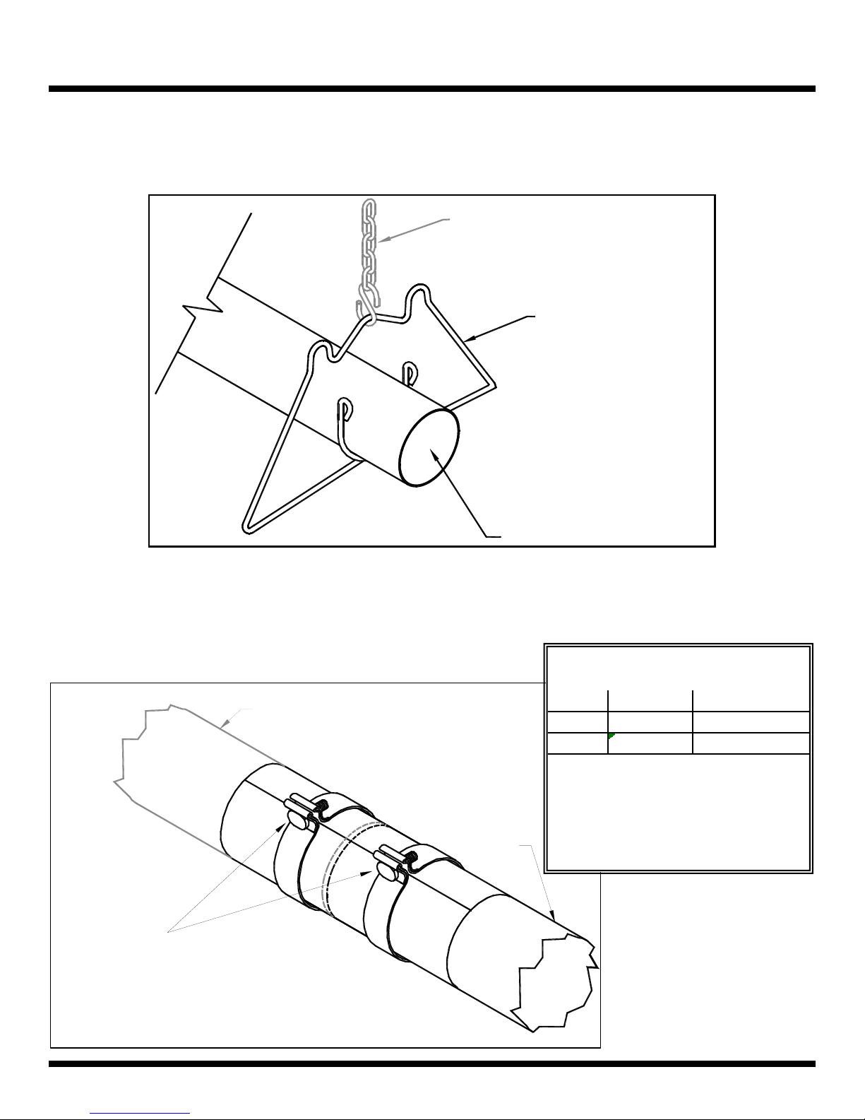
3. Fasten the Reflector Hanger to the end of the hanging chain and place the Tube in the hanger (Refer to
Figure 12). Ensure that Combustion Tubes have the Burner mounting hole positioned at 12 o’clock and
facing downstream (Refer to Figure 17).
Figure 12: Tube & Reflector Hanger Detail
Connect to Turnbuckle
And/Or Ceiling Support Chain
Reflector Hanger
CR003
Combustion / Radiant Tube
4. Join consecutive pieces of Tube using Couplings. Insert one end of both Tubes fully into the Coupling.
(Refer to Figure 13). These should be tightened as the Tubing is put in place, as it is more difficult to do so
once the Reflector is installed. Tighten band clamps alternately to prevent buckling of the sleeve, set to
Torque listed. Ensure that the weld seams on ALL other Tubes are facing down.
Figure 13: Tube Coupling Installationl
Previos Tube
Coupling CR005 S/S or
CR010
Next
Tube
Recommended Static Torque*
for Couplings:
S/S Aluminized
Nm
lb ft
* Stat i c (Audi t ) Torque is defined
as t he am ount of torque required
to rot a t e the nut approxi m at el y
13.5-27 20-34
10-20 15-25
th
1/8
turn in the tightening
direc t i on i m m edi ately after
rundown.
Position coupling in either the 10 o'clock
or 2 o'clock position. Ensure tubes are fully
insertd in the coupling. Tighten Band Clamps
progressively and alternatively to avoid
wrinkles in the liner.
Premier VS Infrared Heating System Page 26 June 04, 2014
Page 27
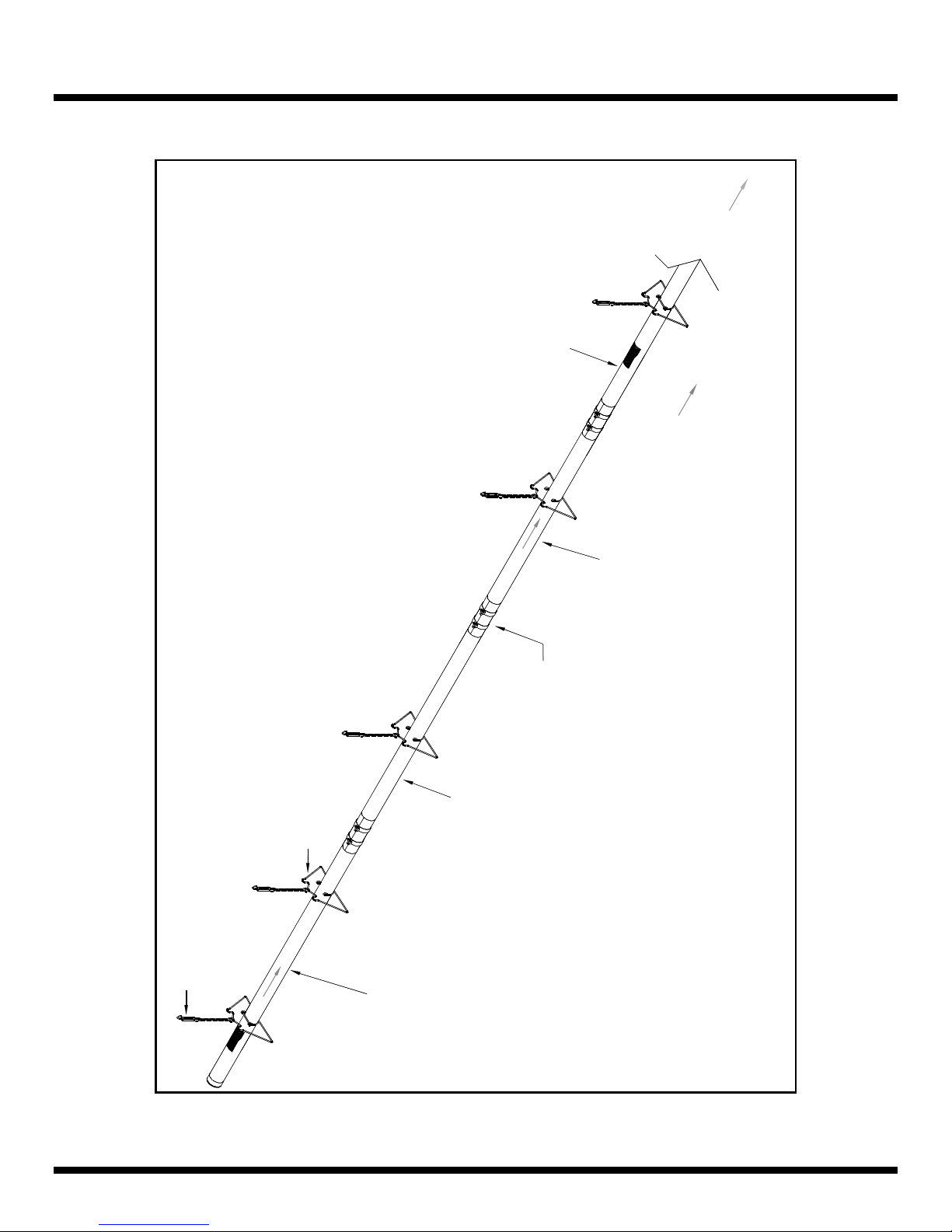
INSTALLATION - Part 1
Figure 14 : View of System after Installation of Radiant Line Tubes
&
e
m
p
i
u
p
u
c
m
a
u
V
P
T
T
o
p
l
i
a
A
w
o
l
o
i
F
ct
r
i
e
r
i
VT001
Combustion Tube
D
CT001 or CT002
Radiant Tube
Coupling
CR005 S/S or CR010
n
Reflector Hanger
Turnbuckles
CH010
System is now ready for Tailpipe installation(s).
System is now ready for Burner installation(s).
Premier VS Infrared Heating System Page 27 June 04, 2014
CR003
VT001
Combustion Tube
CT001 or CT002
Radiant Tube
Page 28
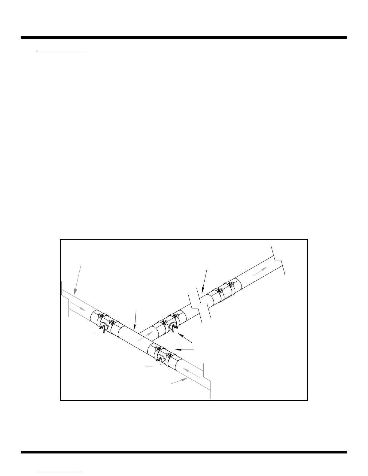
INSTALLATION – Part 1
B - Tailpipe Tubes
1. Continue to install Hangers*, Tubes and Couplings as per Installation Part 1-A: Steps 1 to 3. Ensure that the
mounting height allows a downward slope of ¼” per 10 ft (7 mm per 3 m) towards the Vacuum Pump
location.
*On Tubes which will NOT have Reflectors, i.e. Tailpipe, the use of Hanger Straps instead of Reflector
Hangers is approved.
2. BEFORE installing the Tee Section between the Branch Tailpipes and the Common Tailpipe determine
where the Damper Couplings need to be installed.
3. Check which type of System is being installed, Symmetric (S) or Non-Symmetric (N) as per Figure 1 and
Figure 2. Dampers are positioned to allow the Vacuum Setting at the Branch End Vent to be adjusted
individually for each Branch. Symmetric / Identical Branches require the same Vacuum setting so One
Damper coupling is located before the Tailpipe splits into separate Branches. Non-Symmetric Bra nches
require a separate Damper Coupling for each Branch. For Modulating Rate Systems ensure that Motorized
Damper Couplings are used.
Damper Couplings are ONLY installed in the locations on the System where the respective lette r reference
“S”, OR “N” is located in Figure 15, on all other connections use normal Couplings. Dampers and
Couplings are installed using the same method. (See previous section.)
Figure 15: Typical Tailpipe Connections
m
u
u
c
p
m
u
Branch "B" Tailpipe
Common Tailpipe
o
T
a
V
P
w
o
l
F
n
r
o
i
i
t
A
c
e
r
i
D
4" Tee
S
N
Damper Couplings
CR015 - Manual, Ø 4"
N
Branch "A" Tailpipe
CR070 - Manual, Ø 5"
CR047 - Manual, Ø 4" S/S
CR013 - Manual, Ø 4"
CR014 - Manual, Ø 5"
4. Continue to install the Common Tailpipe in the same manner as all other Tubing. Ensure that the mounting
height allows a downward slope of ¼” per 10 ft (7 mm per 3 m) towards the Vacuum Pump location.
System is now ready for Vacuum Pump and Ventilation connection(s).
Premier VS Infrared Heating System Page 28 June 04, 2014
Page 29
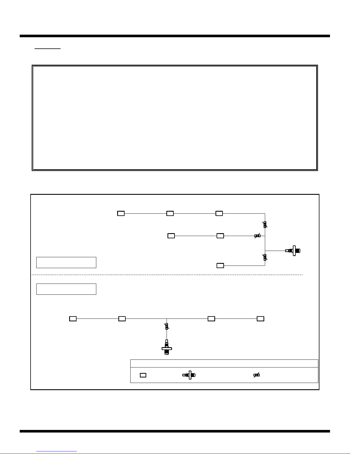
C - Burners
Burner Position No.1 is at the furthest end of the branch from the Vacuum Pump and the
Each Burner is shipped with a Burner Rating Plate & As-Built Burner Position Label affixed,
with the corresponding Air Plate installed. If the System Design Layout changes and the
Burner must be placed in a position other than the As-Built Burner Position then the Air Plate
INSTALLATION – Part 1
Each Burner in a Premier VS Branch must be placed in its appropriate position,
and have the appropriate Air Plate installed.
Burner number increases as the branch runs towards the Vacuum Pump.
(As shown in Figure 16 & referred to in your System Design Layout)
will need to be replaced with the appropriate one for the required new Position.
(See below figure for details.)
Verify that the Burners are correct for the fuel being burned.
Branch A
Example System 1
Example System 2
Figure 16 : Burner Position Reference Diagram
Position 1
Position 2 Position 3
Position 2Position 1
Branch B
Position 1
Branch C
Position 2Position 1
Branch A
Branch B
Position 1Position 2
Premier VS Infrared Heating System Page 29 June 04, 2014
= Burner
Legend
= Vacuum Pump
= Damper Coupling
Page 30
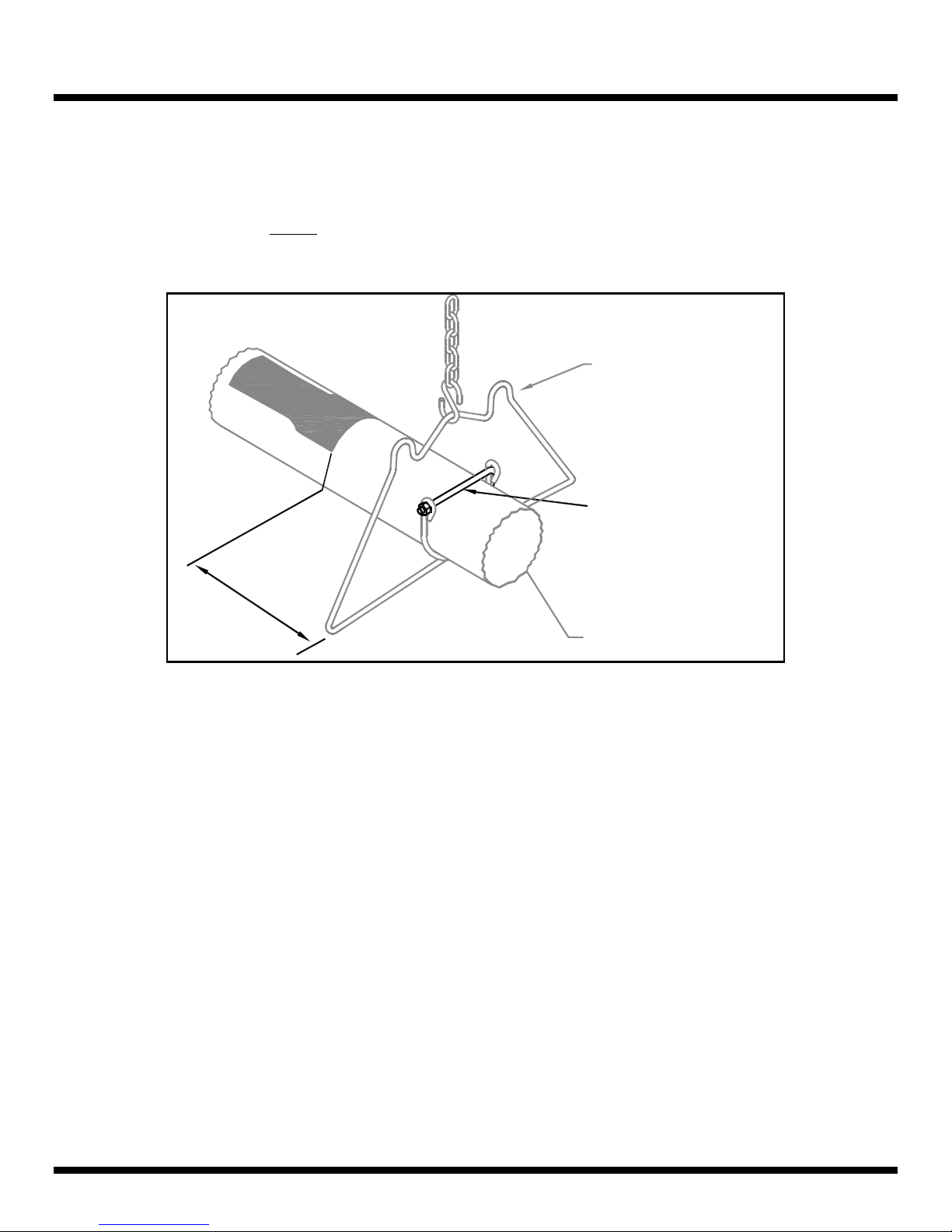
INSTALLATION – Part 1
1. Use the J-bolt (included with the Burner packaging) to clamp the Tube snugly at the first Reflector Hanger
after a Burner mounting hole location. This prevents the Tube from twisting / rotating once the Burner is
installed. (Refer to Figure 9 and Figure 17)
2. J-bolts must be installed before the Reflectors are inserted
Figure 17: J-Bolt Installation Detail
Reflector Hanger
CR003
Before installing Reflec tor:
Install J-bolt on first
hanger after every burner
[ Max. 8" (20 cm) away ]
Max. 8"
Burner to Hanger
Combustion Tube
3. Install each Burner. Ensure the gasket is properly in place, a small amount of contact cement will hold the
gasket. Position the Burner completely to the back of the installation slot as shown in Figure 18. Ensure
that little or no Tube is in view thru the Viewing Glass/ Window.
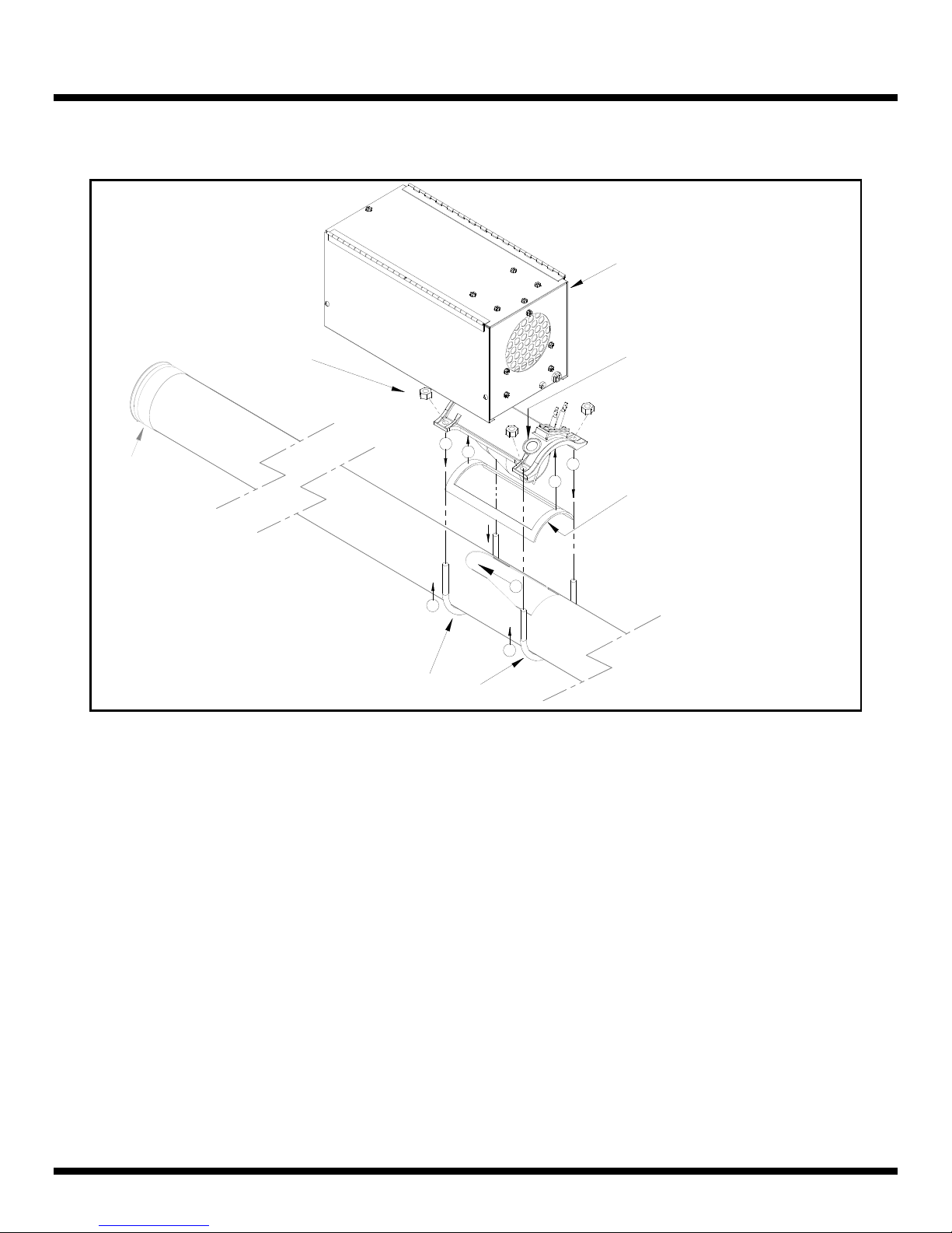
4. Fasten the U-bolts but do NOT over tighten as it will damage the Combustion Tube.
Premier VS Infrared Heating System Page 30 June 04, 2014
Page 31
INSTALLATION – Part 1
Figure 18: Burner Installation
Burner (Position #1)
DO NOT over tighten
the nuts on the U-bolts,
this damages the
End Vent
Cap
Combustion Tube
2 - Align & Fasten Burner to
Combustion Tube with U-Bolts
2
1
3
2
2
1
3 - Make sure the casting is as far
back as possible to ensure the
Viewing Glass on the casting
is not being obstructed and
sight into the Combustion Tube
is being optimized.
Gasket
1 - A small amount of silicone on
each corner of the gasket will help
hold it in place on the underside
of the Burner Casting during
installation.
2
U-bolts
Burners are now ready for Fresh Air Supply connection(s) as necessary.
Burners are now ready for Electrical System connection(s).
Burners are now ready for Gas Supply System connection(s).
Combustion Tube
Premier VS Infrared Heating System Page 31 June 04, 2014
Page 32
INSTALLATION – Part 1
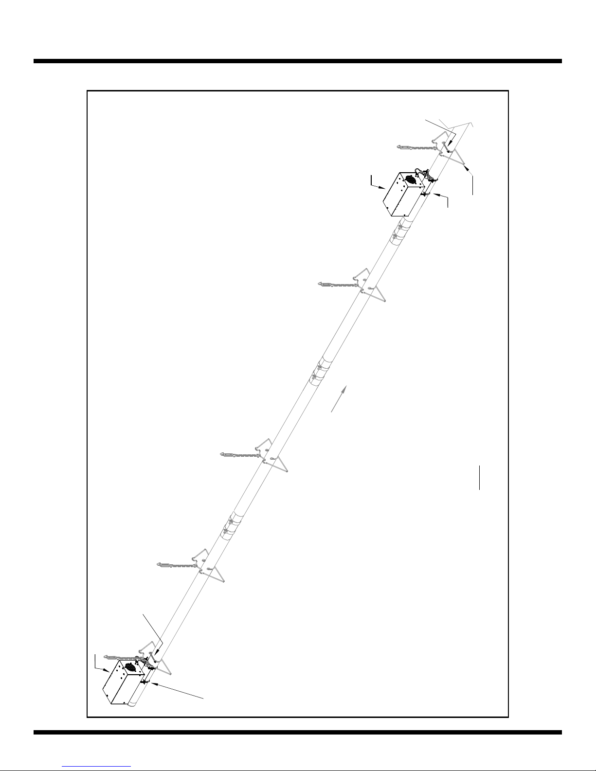
Figure 19 : View of System after Installation of Burners
J-bolt
e
o
p
i
T
p
l
i
a
T
Burner #2
With U-bolts
Secure Burner
Burner #1
J-bolt
w
n
o
l
o
i
t
F
c
r
i
e
r
A
i
D
Install J-bolts only in the Hanger immediately following a Burner
Ensure there is a Hanger a Max. of 8" from the Front of each Burner
Premier VS Infrared Heating System Page 32 June 04, 2014
With U-bolts
Secure Burner
Page 33
INSTALLATION – Part 1
D - Reflectors
1. Install Reflectors after any Tube Couplings and J-bolts they cover have been installed. (For ease of
installation it is suggested to install Burners before the Reflectors; however it is possible to do the reverse.)
2. *If the System Plan includes Bottom Shields these MUST be put on before the Reflectors as there will be
limited access afterwards. For details see Section E - Optional Shield Equipment.
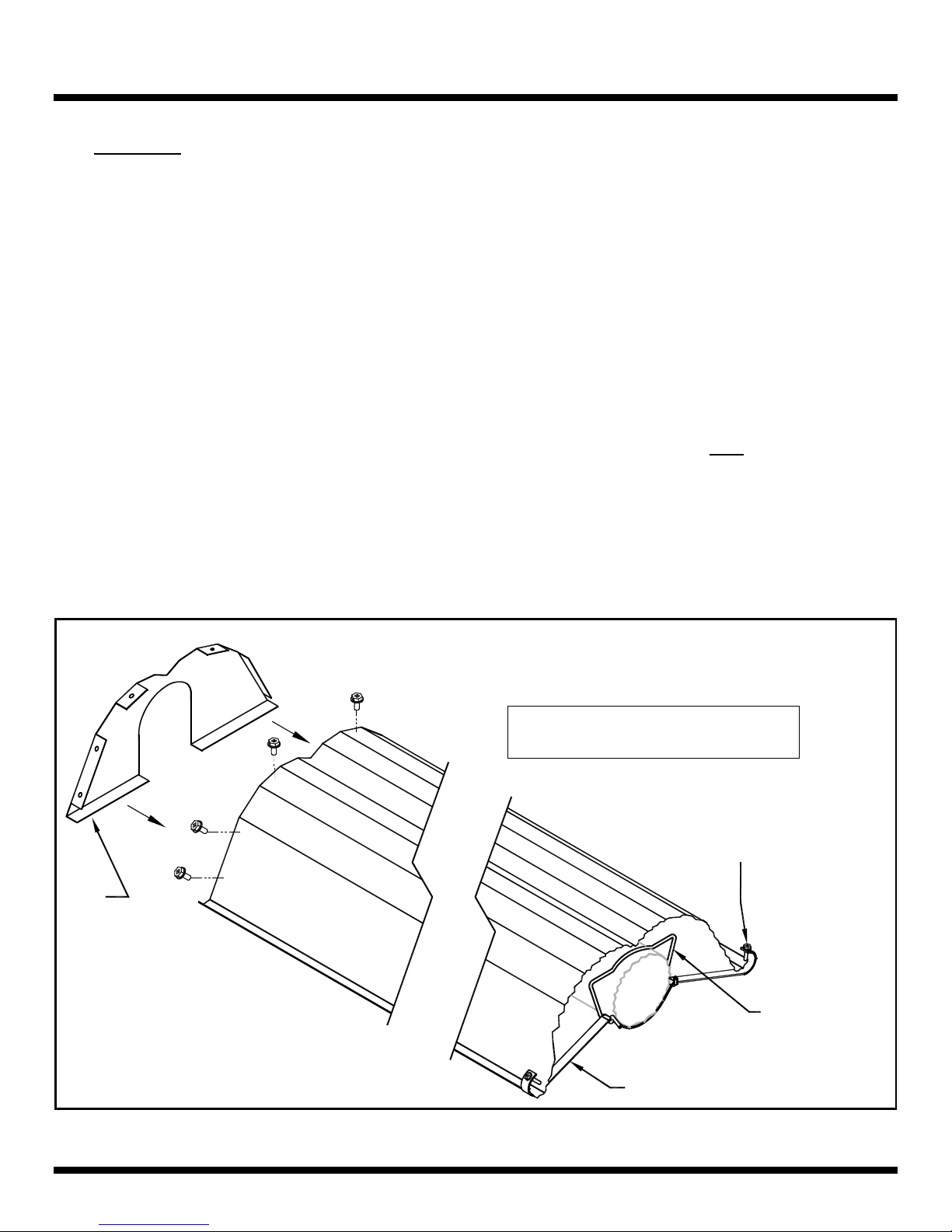
3. Begin the first Reflector after a Burner with an End Cap about 3” (7.6 cm) downstream of the Burner as
shown in Figure 20 & Figure 21. Install the End Cap using #8 x 3/8” screws. Leaving space in the Reflector
run allows unimpeded installation and servicing of the Burner.
4. Install Reflector Brackets. Place one at each Reflector overlap position and one in the middle of each 10 ft
(3 m) Reflector length. Secure the Brackets loosely with #8 x 3/8” screws. Tighten only the screws for
Brackets in the centre of alternating Reflectors & at every second overlap location. The remaining Reflector
Bracket screws are left loose to accommodate system movement / expansion. Refer to Figure 20 below and
to Figure 9 for a visual of which bolts to tighten and which to leave loose.
Reflector
End Cap
CR002
Figure 20: Reflector End Cap & Bracket Detail
Secure End Cap with
Six (6) - #8 x 3/8" screws
Note: Only tighten screws
on every second reflector overlap.
Secure Bracket with supplied
#8 x 3/8" screws and tighten
firmly where required.
Reflector
CR001 / CR032
Premier VS Infrared Heating System Page 33 June 04, 2014
Spring Clip
CR024
Reflector Bracket
Page 34
INSTALLATION – Part 1
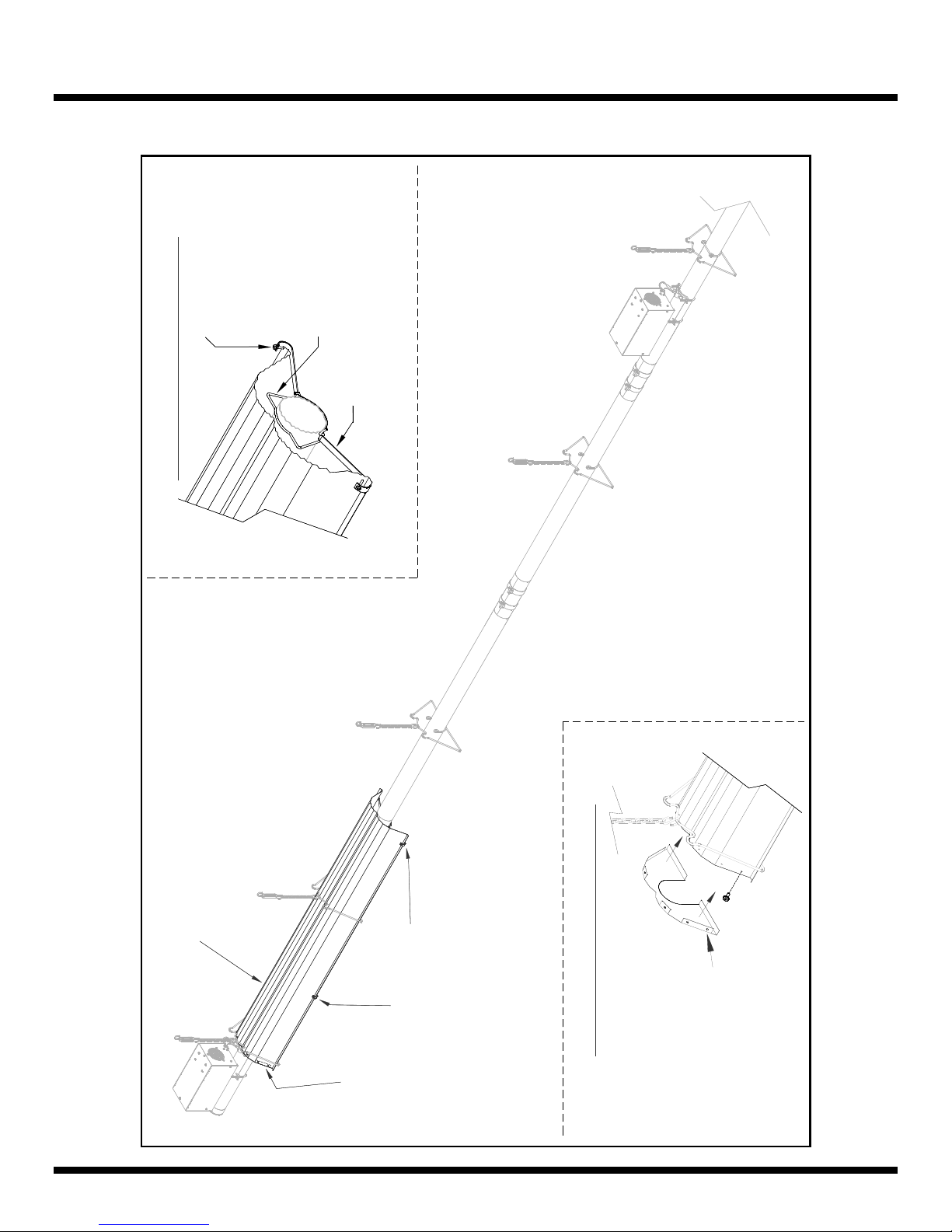
Figure 21 : View of System after Installation of first Reflector
#8 x 3/8" screws and
tighten firmly where
Secure support with
required.
Spring Clip
CR024 (Set)
Reflector Bracket
Reflector Bracket Details
CR001 / CR032
Reflector
Premier VS Infrared Heating System Page 34 June 04, 2014
End Cap
Reflector
Reflector
Clip Sets
Bracket &
CR002
CR024
Reflector End Cap Details
Reflector End Cap
with #8 x 3/8" screws (x6)
Secure End Cap
CR002
Page 35
INSTALLATION – Part 1
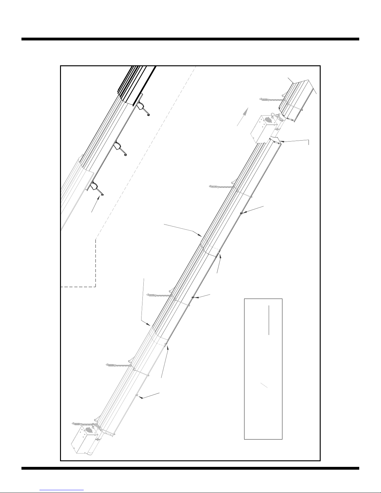
5. Continue to slide the Reflectors into place within the Tube/Reflector Hanger up to the next Burner position.
Overlap the Reflectors as shown in Figure 9 and Figure 23.
DO NOT install Reflectors like roofing shingles, by overlapping the same end of the reflector every time.
This will cause damage once the system heats up and components start to expand.
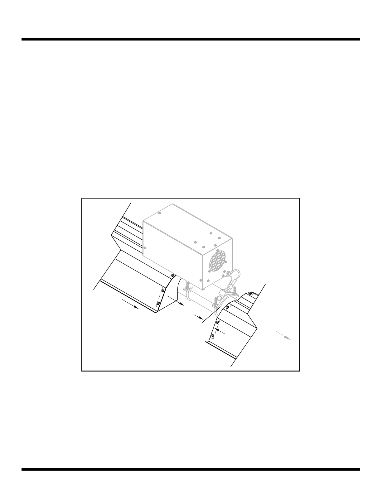
6. When approaching successive Burner locations, ensure the Reflector is as far under the Burner (close to the
Burner mounting hole) as possible, as shown in Figure 22. *Install an End Cap using #8 x 3/8” screws on
the open end of the Reflector which will be under the Burner at the end of the Reflector run.
*Burner Reflectors are for use instead of End Caps. If Burner Reflectors, for Continues Reflector runs,
are required by the System Plan please refer to Section E - Optional Shield Equipment for alternate
Reflector installation details.
Figure 22: Standard Reflector & Burner Relative Positioning
Place Reflectors
as far under Burner
housing as possible.
3"
Max.
A
i
r
F
D
l
o
i
r
e
c
t
i
o
w
n
7. Stop the Reflector run as per plan or when reaching an Elbow or Tee and install an End Cap at the end of
the Reflector run using #8 x 3/8” screws.
*When using the optional Corner / Mitered Reflectors refer to Figure 26 in Section E - Optional Shield
Equipment, for details on how to assemble Reflectors sections instead of installing End Caps.
Premier VS Infrared Heating System Page 35 June 04, 2014
Page 36
INSTALLATION – Part 1
Figure 23 : View of System after Installation all Reflectors
Overlap
V
O
as shown
Reflectors
R
E
U
N
D
E
R
O
V
E
R
w
n
o
l
o
ti
F
c
r
i
e
r
A
i
D
with screws
Fasten End Caps
Tight Screws
Reflectors (CR001 / CR032)
CR024
Reflector Brackets
(overlap approx 4")
Loose Screws
Tight Screws
") on every second
4
1
Reflector & overlap ONLY
(#8-3/8 x 1
Tighten Reflector Bracket screws
Premier VS Infrared Heating System Page 36 June 04, 2014
Page 37
INSTALLATION – Part 1
E - Optional Shield Equipment
Bottom Shields
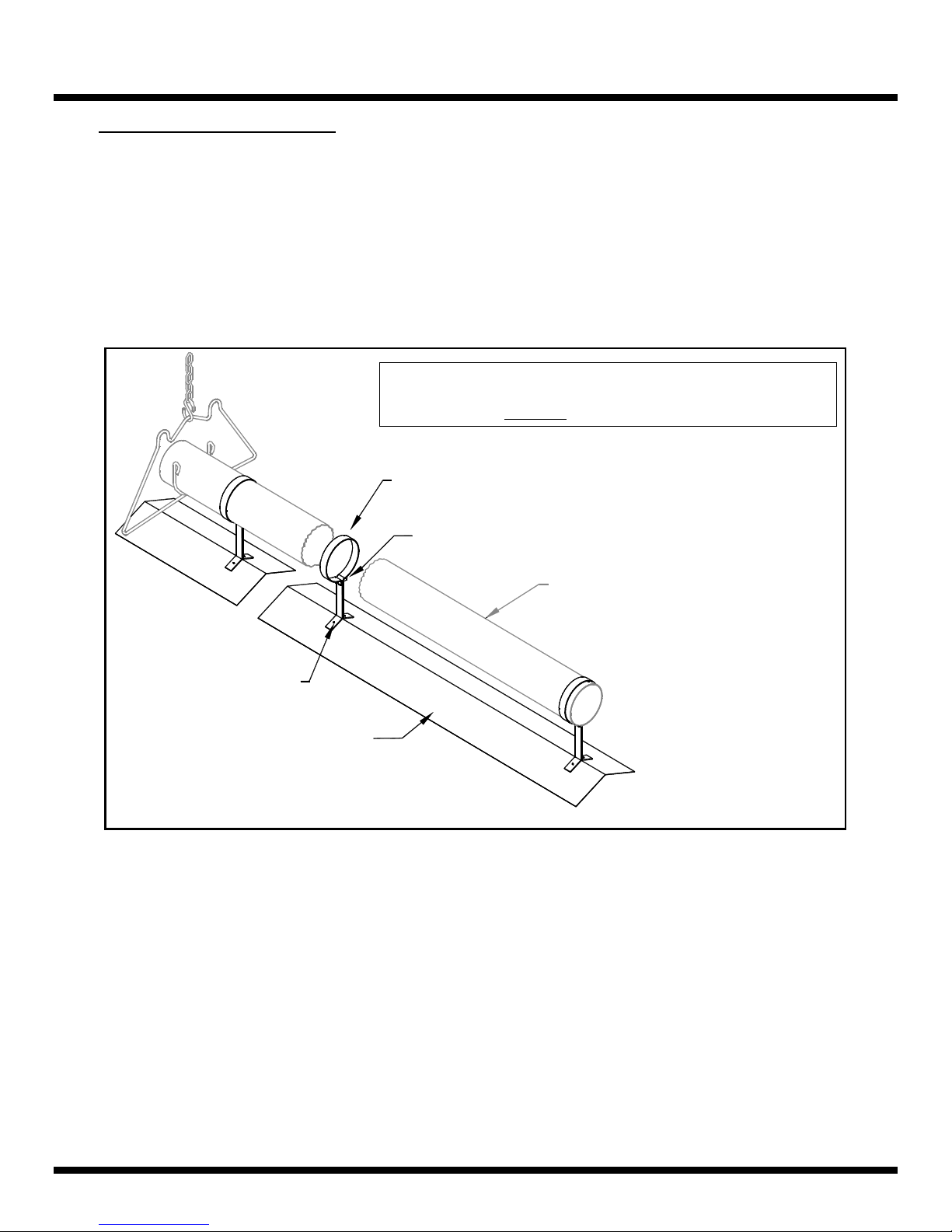
Bottom Shields do not need to overlap. Each 5 ft (1.5 m) section is held with two Support Brackets. Secure each
of the Support Brackets around the Tube with a #8 x 3/8” screw.
Refer to Figure 24 below for reference.
Figure 24: Bottom Shield Installation Detail
It is easier to insta ll B o tt o m Shield
assemblie s
before Reflecto rs ar e in -p la ce .
Bottom Shield Bracket
CR017
Install Brackets, tighten screws
Tube Section
#8 x 3/8" Screws
Bottom Shield
CR018
Secure Bottom Shields to Brackets after
Brackets are installed on Tubes
Burner Reflectors
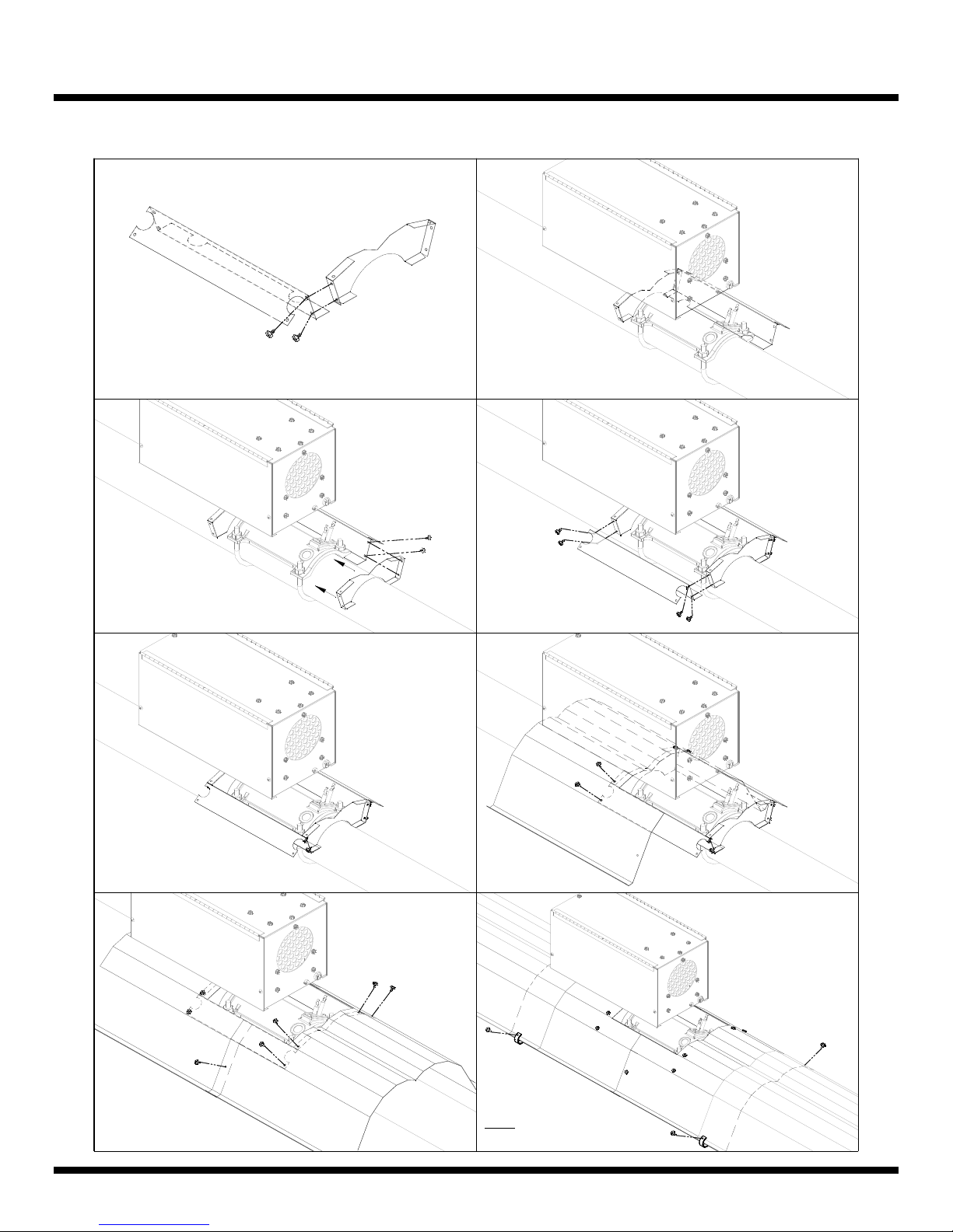
Burner Reflectors are used to maintain a continuous Reflector surface along the length of the Heat Exchanger
instead of ending & restarting Reflector runs with End Cap s at each Burner location.
Burner Reflectors are installed after the Burner installation, and before / during assembly of the main Reflector
run. All pieces are connected using #8 x 3/8” Screws. The Side pieces and End Sections are installed first to
create a Base to secure the Burner Reflector sections to. Overlap the Burner Reflectors with Standard
Reflectors, secure the Reflectors together with Support Brackets. Refer to the sequence of images in Figure 25
for more detail.
Premier VS Infrared Heating System Page 37 June 04, 2014
Page 38
INSTALLATION – Part 1
Figure 25: Burner Reflector Installation Sequence Details
VR003
Install screws through one Side Segment
into one End Cap
Attach second End Cap
to first Side Segment
1
Position under Burner
2
34
Attach second Side
Segment to both End Caps
Base of Burner Reflector
is now assembled
Secure the second
Burner Reflector Section
on top of the Base
6
Overlap with main
Reflectors and secure
each in-place with one
Bracket and 2 Screws
5
Secure one
Burner
Reflector
Section
on top of the
Base
(4 Screws)
7
Finished
Premier VS Infrared Heating System Page 38 June 04, 2014
Page 39
INSTALLATION – Part 1
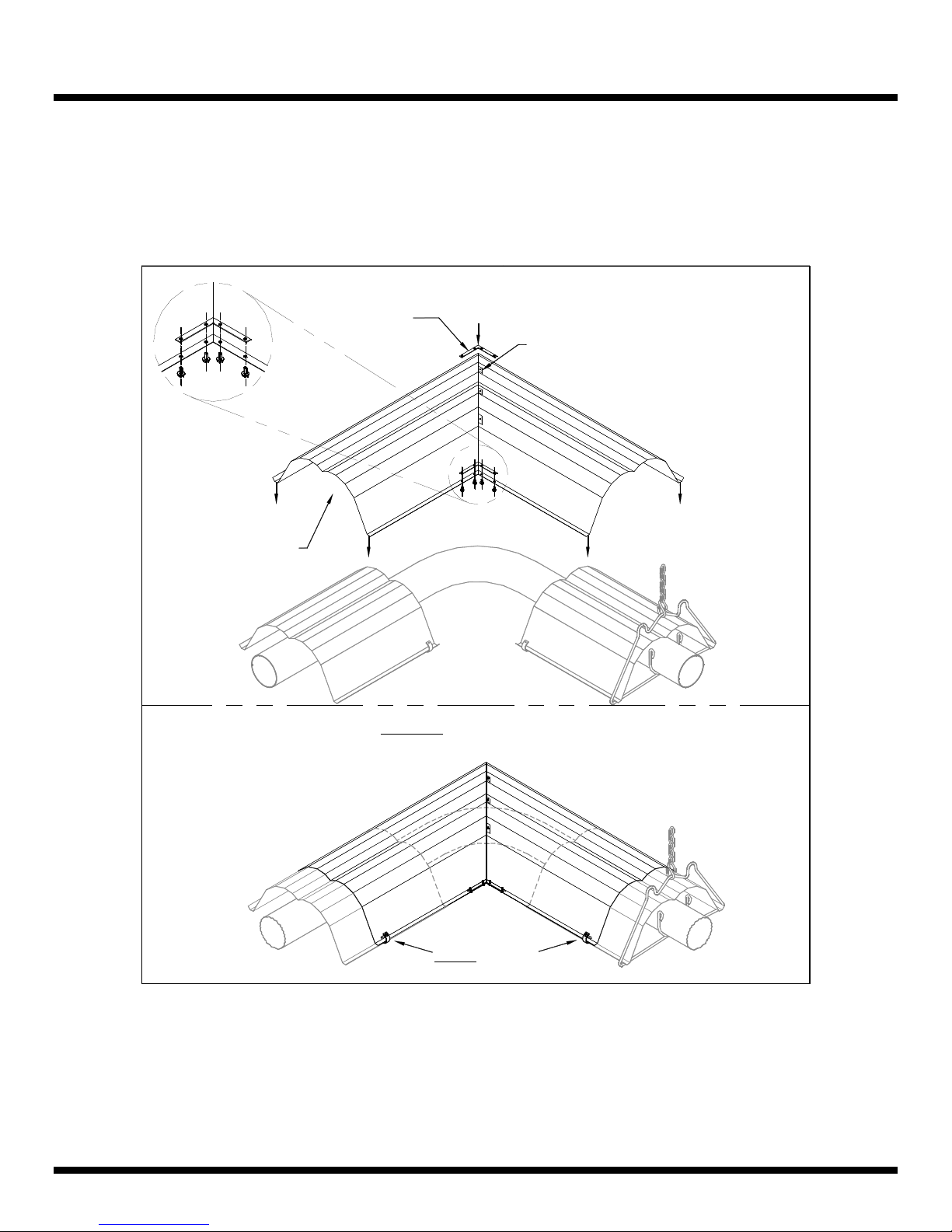
Corner / Mitered Reflector
Corner / Mitered Reflector Kits are used above elbow locations instead of stopping and restarting a Reflector
run to accommodate the elbow. Secure the Mitered Reflectors together using the Two (2) Corner Brackets as
shown in Figure 26. Also insert #8 x 3/8” screws at each ‘tab’ location along the top of the Reflectors.
Figure 26: Optional - Corner (Mitered) Reflectors
Assemble Corner Brackets to
Mitered Reflectors as shown
Fasten Mitered Reflectors
with 4 #8 x 3/8" Screws
CR039
Mitered Reflector
Kit
Mitered Reflector
sections should
overlap Standard
Reflectors by
at least 4".
Assembled Sections: Tighten screws on Reflector Brackets at both sides.
Ensure sequence of Tight / Loose screws on Reflector run starts from this point.
Tight screws
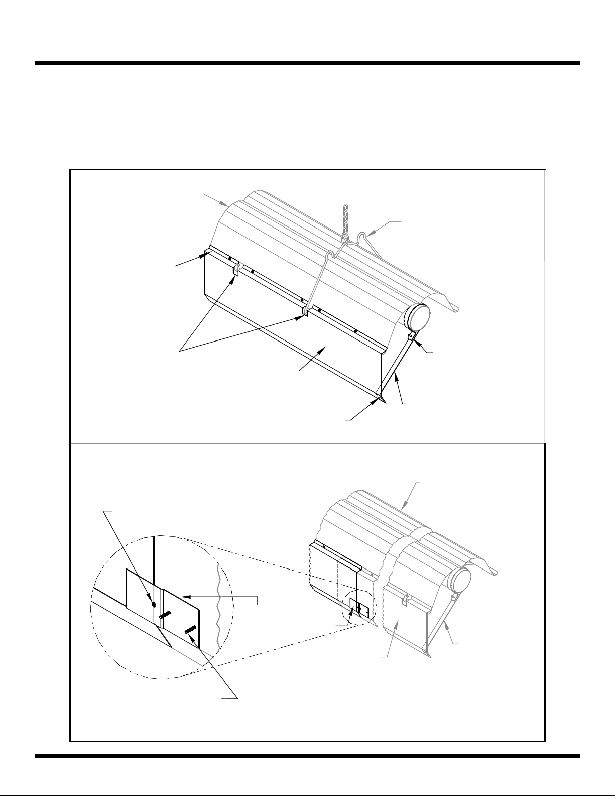
Side Reflectors
Side Reflectors are 124” (3.15 m) long. Fasten one Side Reflector per main Reflector tightly with #8 x 3/8”
screws spaced about 18” (0.5 m) apart. Install three (3) Side Reflector Brackets per Side Reflector, spaced
about 48” (1.2 m) apart, using #8 x 3/8” screws. DO NOT tighten screws where Reflectors overlap. Refer to
Figure 27 on the following page for details.
Premier VS Infrared Heating System Page 39 June 04, 2014
Page 40
INSTALLATION – Part 1
Install Side Reflector Retainer Clips when connecting / overlapping Side Reflectors.
Side Reflectors should be independent of each other. They should overlap approximately 2-4” (5-10 cm) but
with no physical connection between them. This will allow for movement with thermal expansion of the Tube
& main Reflector.
Figure 27: Side Reflector Installation Detail
Reflector
Reflector
Hanger
#8 x 3/8" Screws
Notch the Side Reflector
for Reflector Brackets
and Hangers
Side Reflector
CR019
#8 x 3/8" Screw
Use the hole as a guide to position Side Reflector.
The Side Reflector edge must be visible through
the hole at room temperature.
Side Reflector
Retainer Clip
CR035
Side Reflector
CR019
#8 x 3/8" Screw
Side Reflector Bracket
(approx. 48" apart)
CR016
Reflector
Side Reflector
Bracket
CR016
Screws to be installed from inside of Side Reflector.
Install screws on one end of the Retainer Clip to allow movement.
Premier VS Infrared Heating System Page 40 June 04, 2014
Page 41
INSTALLATION – Part 1
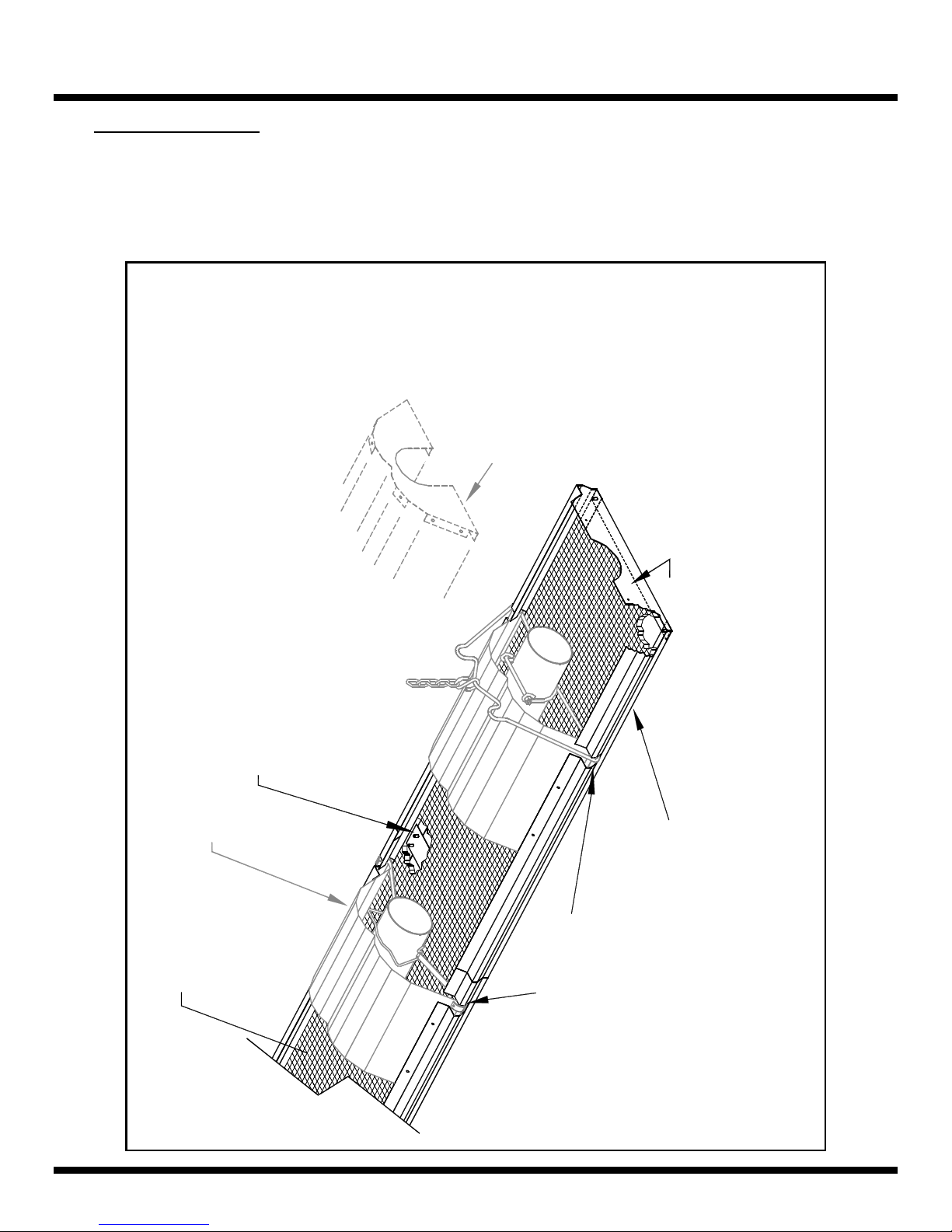
F - Deco-Grille Option
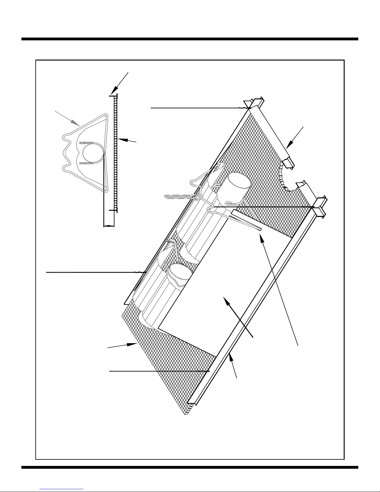
Premier VS System heaters are approved for the addition of a Decorative Grille [Deco-Grille] either directly to
the Reflector or as part of a T-bar installation where the Heater System is above the ceiling structure. Refer to
Figure 28 and Figure 29 below for their respective details.
Figure 28: Deco-Grille – Mounted Directly To Heater
as usual
Install End Cap
CR053
Deco-Grille Cross Strap
At Every 5ft Section
Fasten with Screws
Reflector
Deco-Grille Panel
Notch
for Hangers
CR054
CR052
& Supports
Deco-Grille Support
Deco-Grille Supports
Fasten to End Cap &
Deco-Grille End Angle
Shield and hold with
Install from Outside of
Screws from Outside
Premier VS Infrared Heating System Page 41 June 04, 2014
Deco-Grille Support
Page 42
INSTALLATION – Part 1
Figure 29: Deco-Grille – Mounted With T-Bar
T-bar
T-bar Shield
CR027
Reflector Hanger
CR026
Deco-Grille Panel
2" Min.
CR026
Deco-Grille Panel
CR059
Side Shield
Premier VS Infrared Heating System Page 42 June 04, 2014
(Cut to fit Deco-Grille)
T-bar Suspended
Ceiling
Notch Side Shield as required for
Reflector Brackets and Hangers
Page 43

INSTALLATION – Part 2
Part 2 - Vacuum Pump & Venting
Vacuum Pump
General Requirements
The Vacuum Pump (with permanently mounted motor affixed) is generally located at the height of the system,
bolted to a platform or support structure that is either suspended from the ceiling members or is bolted to a
column or building sidewall. The Vacuum Pump scroll is orientated for the preferred horizontal discharge, but
can be rotated 90 degrees in the field for vertical discharge.
(Refer to Figure 30, Figure 31 and Figure 32 for visuals of Vacuum Pump mounting options.)
*If a lengthy heater run has a 90 degree elbow with a short run to the Vacuum Pump, consider placing the Pump
somewhat off (past) the centerline of the connecting Tailpipe so that as the system grows the Flexible Boot
Connection in fact improves performance.
Safety Warnings
Confirm that the Vacuum Pump’s impeller rotates in the same direction indicated by the arrow on the pump
scroll. To reverse rotation, see instructions on the motor.
WARNING - DO NOT OPERATE THE VACUUM PUMP WHEN NOT INSTALLED
- Unguarded openings can entangle clothing and severe injury can result
- Unrestricted air flow into Vacuum Pump can cause the motor to overload
To ensure maximum safety, a vacuum proving switch is mounted near the inlet of the vacuum pump and
electrically interlocked to the burner power circuit. No fuel gas can flow or ignition begin before the
vacuum proving switch has established the presence of a blower induced vacuum.
See the “Electrical Connections” section for details on wiring the switch.
Premier VS Infrared Heating System Page 43 June 04, 2014
Page 44
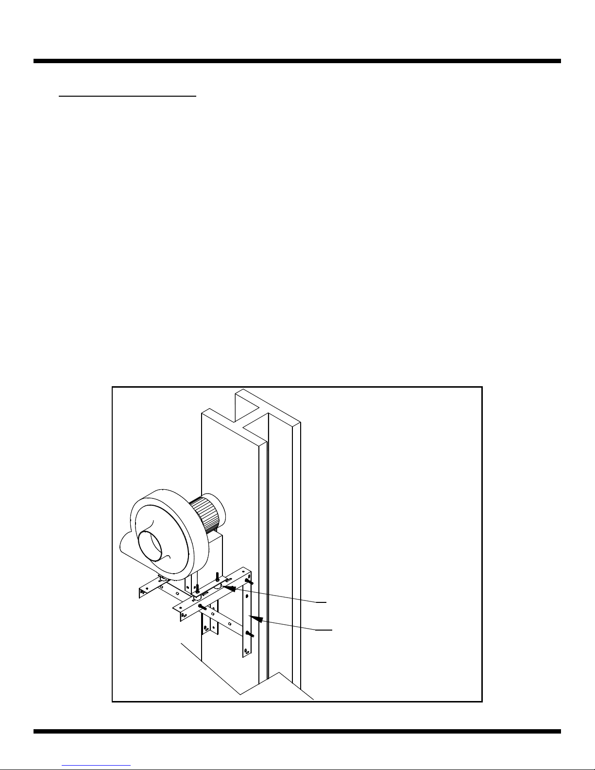
INSTALLATION - Part 2
A - Vacuum Pump Mounting
1. Install Vacuum Pump as per designed system mounting location and position.
2. Ensure that mounting supports are sufficient to withstand the weight and vibration of the Vacuum Pump and
Ventilation System. Welded link chain with a working load limit of at least 200 lbs. (91 kg) is recommended
for mounting vacuum pumps only.
3. Install using the Vacuum Pump Mounting Kit if purchased. (Chain & threaded rods for ceiling mounting
are NOT included in package.)
4. Ensure elevation of Inlet will allow for the alignment of the Tubing with a downward slope of ¼” per 10 ft
(7 mm per 3 m) towards the Vacuum Pump.
5. Ensure that the isolators are placed between the Pump housing and the mounting supports to reduce
vibration transfer to the structure.
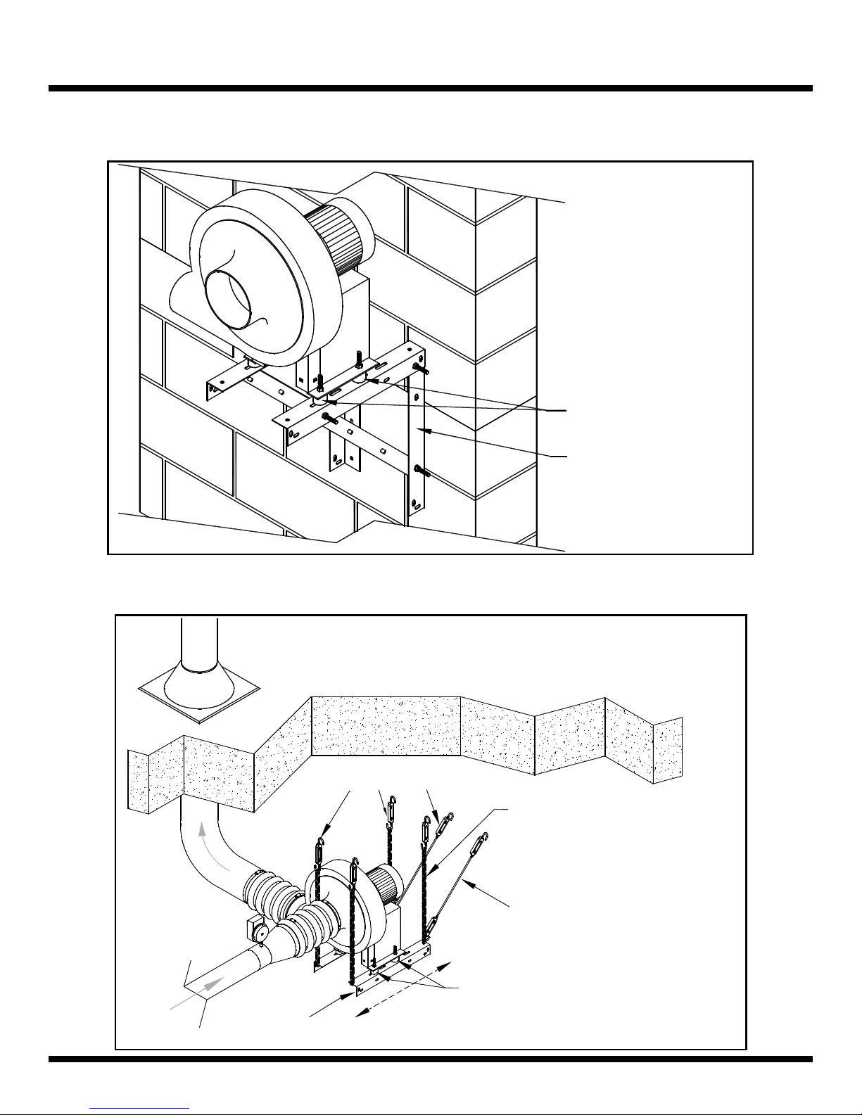
See Figure 30, Figure 31 or Figure 32 respectively for mounting type details.
Figure 30: Column Mounting – Recommended Pump Suspension
Mount bracket to
column with
suitable fasteners.
Premier VS Infrared Heating System Page 44 June 04, 2014
Isolators
VH010
Mounting Kit
Page 45
INSTALLATION - Part 2
Figure 31: Side Wall Mounting - Recommended Pump Suspension
Mount bracket
to wall with
suitable fasteners.
Isolators
VH010
Mounting Kit
Figure 32: Ceiling Mount - Recommended Pump Suspension
Turnbuckles for height adjustment.
Welded link chain with a working
load limit of at least 200 lbs. (91 kg)
is recommended for mounting
vacuum pumps only.
w
o
l
F
n
r
o
i
i
t
A
c
e
r
i
D
Premier VS Infrared Heating System Page 45 June 04, 2014
Mounting Kit
VH010
When suspending from ceiling,
add threaded rod to prevent
horizontal movement of pump.
Isolators
Page 46

INSTALLATION - Part 2
Venting
The Premier VS System is approved for both Sidewall (Horizontal) and Roof (Vertical) Venting.
(Refer to Figure 33 and Figure 34)
General Requirements
Venting must comply with the National Fuel Gas Code, ANSI Z223.1/ NFPA-54 in the USA and CAN/CGA
B149.1/B149.2 Installation Code in Canada.
Note: ANSI Z223.1 specifies a minimum 4 ft (1.22 m) horizontal vent terminal clearance from gas and
electric meters, regulators and relief equipment (see clause 1/31/3-m4).
Items Common to both Codes:
(always check for changes to Code – list is for example only)
Horizontal discharge must be not less than a specified distance above grade
Vent must not terminate within a specified distance below, horizontally from, or above any window,
door or gravity opening to a building.
Discharge must be at least a specified distance from any opening through which vent gases can enter a
building.
Venting must terminate beyond any combustible overhead and at a height sufficient to prevent blockage
by snow.
Venting through a combustible wall requires an approved thimble.
Vent should extend beyond wall surfaces to avoid splash-back condensation.
Corrosion resistant materials should be employed for venting.
General Installation Notes
Never connect venting to a chimney flue serving a separate solid-fuel burning appliance.
Rigid, spiral wrap, corrosion resistant ducting is recommended to facilitate leak-proofing the system.
Venting runs over 25 ft (7.6 m) in length may need to be insulated.
Always install venting with a down-slope of at least ¼” per 10 ft (7 mm per 3 m) towards the Vacuum
Pump location.
Ensure that ducting is well suspended to avoid low spots where condensate can gather.
Seal ALL joints using higher temperature Silicone Sealant. (RTV Silicone)
Premier VS Infrared Heating System Page 46 June 04, 2014
Page 47

System Requirements
Horizontal Venting:
Material:
Size:
Sealant:
Fasteners:
Minimum 24 gauge, GALV, single wall Pipe
4 " or 6 " dia. as per Vacuum Pump Outlet
RTV Silicone
Minimum of Two (2) sheet metal screws #8 x 3/4" per joint.
INSTALLATION - Part 2
Table D: Size Conditions for Exhaust Venting
For specific Part Numbers of Wall Vent connection pieces see Figure 33 OR the
listing in the PARTS section of this manual.
Vertical Venting:
For Vertical Venting refer to ANSI Z223.1 and CAN/CGA B149.1 for Fan Assisted
Appliances.
Premier VS Infrared Heating System Page 47 June 04, 2014
Page 48
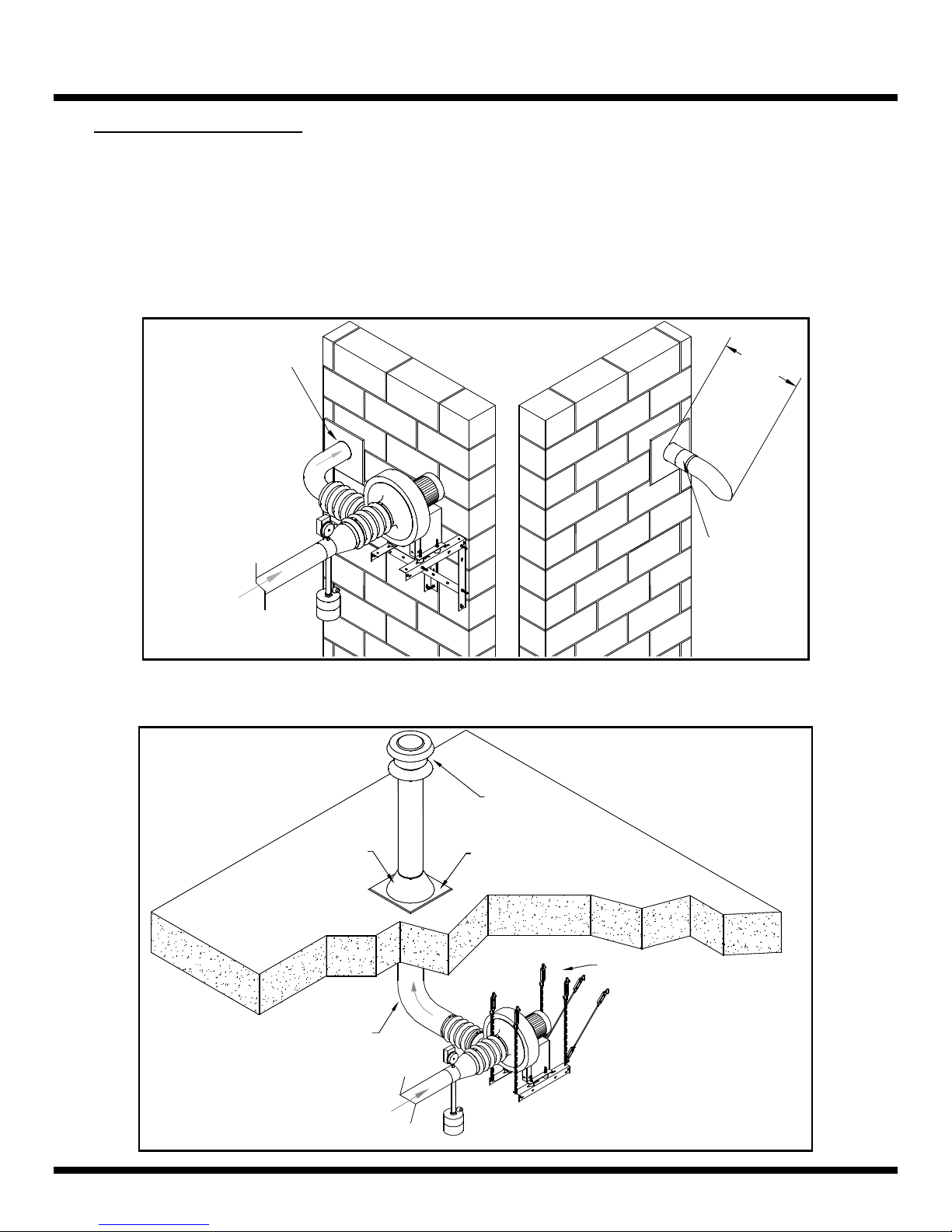
INSTALLATION - Part 2
B - Ventilation Connections
1. Install Ventilation system pipes, etc. as per design / conformance with required Codes and connect with
Vacuum Pump Outlet. Ensure that there is a minimum of 2” (5 cm) between the Vacuum Pump outlet and
the first rigid section of the Ventilation piping to avoid mechanical contact between the two. Use the
Silicone Connector Boot to connect the Vent Pipe to the Vacuum Pump Outlet.
(Refer to Figure 33 or Figure 34 respectively for mounting type details.)
Figure 33: Side Wall Mounting - Recommended Venting (Horizontal)
Approved wall thimble
(if necessary)
4" Ø: CS006
6" Ø: CS033
18" Min.
24"-26"
Preferred
Vent Terminal
4" Ø: CT011
w
o
l
F
n
r
o
i
i
t
A
c
e
r
i
D
6" Ø: CT044
Figure 34: Ceiling Mounting - Recommended Venting (Vertical)
Rain Cap
Flashing
Approved Thimble
(If Necessary)
Fasten To Ceiling Bolts
FOR VERTICAL VENTING REFER
TO ANSI Z223.1 AND CAN/CGA B149.1
AND B149.2 FOR FAN ASSISTED
APPLIANCES.
Premier VS Infrared Heating System Page 48 June 04, 2014
w
o
l
F
n
r
o
i
i
t
A
c
e
r
i
D
Page 49
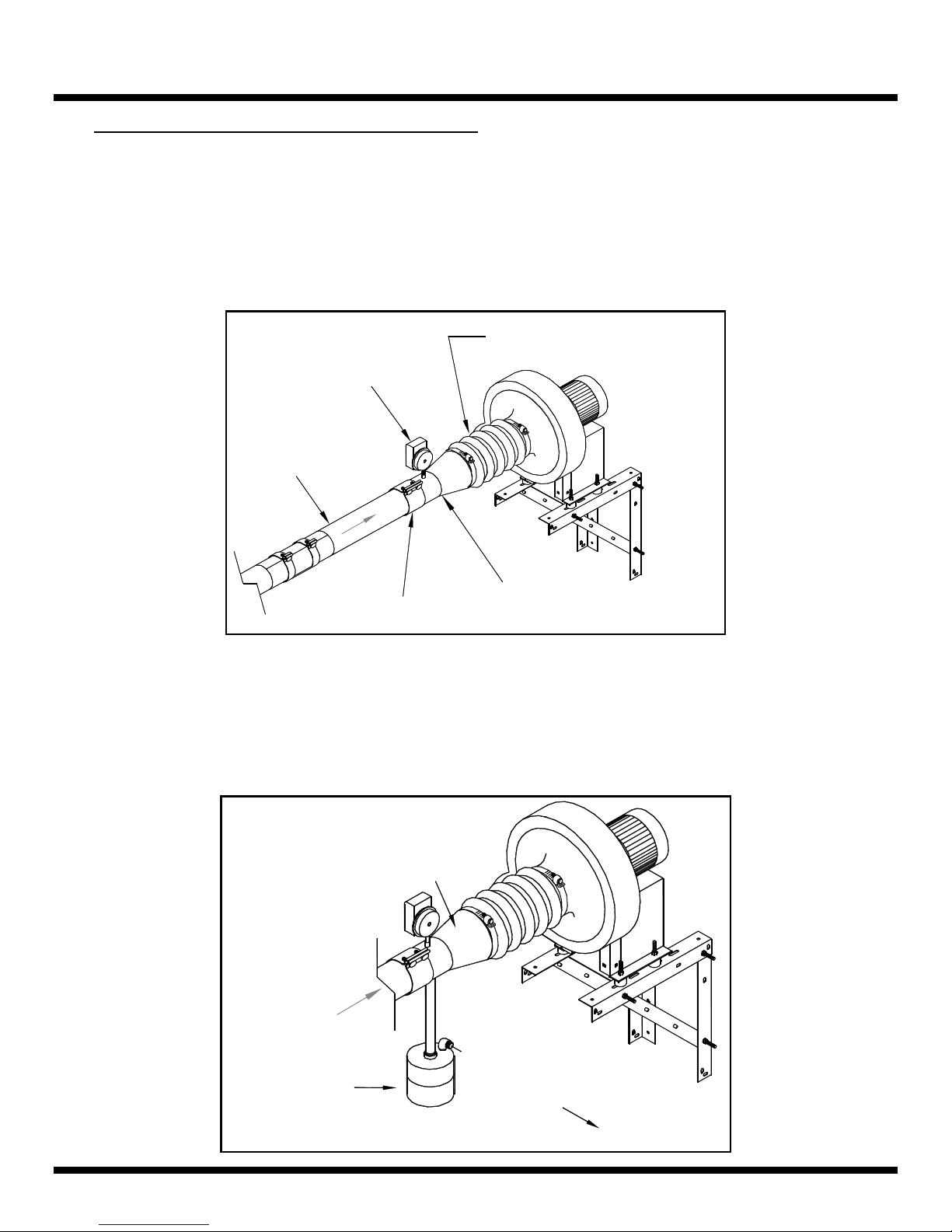
p
INSTALLATION - Part 2
C - Additional Pump Connections & Equipment
1. Connect the Reducer to the end of the Common Tailpipe using a 4” Butt Joint Clamp. Ensure a minimum
of 2" (5 cm) clearance between the Reducer and the Pump Inlet.
2. Install the Flexible Boot Connector between the Reducer and Pump Inlet, to reduce vibration and noise
transmission, using a gear clamp at either end, as shown in Figure 35.
Figure 35: Tailpipe to Vacuum Pump Connections
Vibration Boot
Package
Vacuum Switch
VE007
4" Common
Tailpipe
(6" Ø shown)
4" Ø: VS010
6" Ø: VS048
w
o
l
F
n
r
o
i
i
t
A
c
e
r
Di
Butt Joint
Clam
CR046
6" To 4" Reducer
CT048
3. Seal all joints and seams using high temperature Silicone Sealant (RTV Silicone).
4. Where condensing designs are specified, a Condensate Drain may be installed as shown in Figure 36.
Ensure connection to Drain Pipe is flexible to allow for system movement / expansion during operation, and
that an appropriate Neutralization Device is installed as required.
Figure 36: Condensate Drain Detail - Optional
6" to 4" Reducer
w/ Vacuum Switch
VE007
F
r
i
A
r
i
D
Condensate Trap
VH004
Premier VS Infrared Heating System Page 49 June 04, 2014
l
e
ow
t
c
n
o
i
1
/
2
"
T
o
o
r
D
N
D
e
r
e
v
a
u
i
in
t
r
a
l
i
z
a
c
t
e
i
o
n
Page 50
INSTALLATION - Part 3
Part 3 - Optional Combustion Air Supply
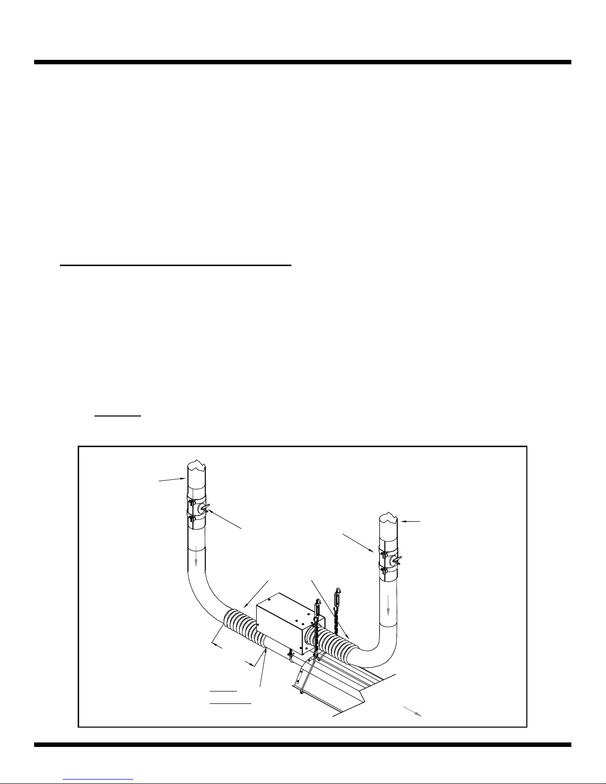
An air supply at atmospheric pressure of 40 CFM per 100,000 BTU/hr to each Burner and the end of each
Radiant Branch (at the End Vent Cap) is usually sufficient.
Under certain circumstances of very dirty or wet environments, or extremely negative building pressure, a
Combustion Air Supply System that is connected to the fresh air outside the building may be recommended.
The Combustion Air Supply System must be designed with accepted HVAC design methods to ensure adequate
supply of air to each Burner and Radiant Branch. This Combustion Air can be supplied using a Blower. Supply
at the Burner must be at atmospheric pressure therefore it may be necessary for the Installer to insert Damper
Couplings to allow adjustment of pressure just before the connection to each Burner and at the end of each
Branch. The Blower must be electrically interlocked with the Vacuum Pump, details can be found in
“Electrical Connections”.
A - Combustion Air Supply Duct Connections
1. Install Blower if required.
2. Install Combustion Air Supply ductwork and Damper Couplings as required.
3. Each Burner can be fitted with a 4” dia. fitting to accept 4” dia. Type C-Duct or 4” PVC pipe. Provision for
thermal expansion of the System must be made when considering Combustion Air Supply Ducting. Ensure
that the System movement / expansion does not restrict the supply of fresh air to the Burners or the Radiant
Branches. (Refer to Figure 37 for clearance requirements)
As required, connect the Supply Ductwork in the same manner as for the Burner. (Refer to Figure 37 for
details), DO NOT remove the End Vent Cap from the Radiant Branch to make this connection.
* Dampers are to be provided by Installer,
as necessary, to obtain atmospheric
To Outside Air:
Directly to Outside
or to Common
Ductwork
from Blower
Outside Air Dampers*
Flex Duct
pressure at the Burner(s)
To Outside Air:
Directly to Outside
or to Common
Ductwork
from Blower
12" Min.
for all Flex Ducts
Premier VS Infrared Heating System Page 50 June 04, 2014
Note:
DO NOT Remove
End Vent Cap
D
A
i
r
F
l
o
i
r
w
e
c
t
i
o
n
Page 51

INSTALLATION – Part 4
Part 4 - Gas Supply System
General Requirements
Supply Lines
The Gas Supply Meter and the Supply Service must be sufficiently large to supply gas to the total building gas
load including the heating equipment. Additionally, the gas distribution piping must be designed according to
local and national ordinances. Generally, systems designed with a maximum ½” W.C. total pressure drop (low
pressure) meet this requirement.
Gas supply pipe sizing must be in accordance with the National Fuel Gas Code, ANSI Z223.1 (NFPA 54) in the
US and CAN/CGA B149.1 and B149.2 Installation Codes in Canada.
A 1/8” NPT plugged tap must be installed in the Gas Line connection immediately upstream of the Burner
farthest from the Gas Supply Meter to allow checking of system gas pressure.
A Gas Shut-off Valve must be installed parallel to EACH Burner Gas Inlet connection.
Before connecting Burners to the Gas Supply System, verify that high pressure testing of the Gas System
has been completed. Burners must be isolated from any pressure testing in excess of ½ psi (3.5 kPa).
Failure to comply may expose the Burner components to damaging high pressure, requiring replacement of key
components.
Flexible Gas Connector Lines
Gas Flex Line Connector sizes for Burners with firing rates: (1 MBH = 1 000 BTU/hr)
o Below 150 MBH, requires ½” dia. x 36” (90 cm) long
o At 150 MBH or higher, requires ¾” dia. x 36” (90 cm) long
In Canada: Only use Type I Hose Connector that is (a) certified as being in compliance with the Standard for
Elastomeric Composite Hose and Hose Couplings for Conducting Propane and Natural Gas, CAN/CGA 8.1;
and (b) of a length of 36” ± 6” (90 ± 15 cm).
In the United States: The Flexible Metallic Connector Hose must be certified for use on a Radiant Tube type
Infrared Heater per the Standard for Connectors for Gas Appliances, ANSI Z21.24/CSA 6.10.
Failure to install the Gas Connection in the approved manner will result in a hazardous and potentially
deadly situation due to the movement of the heat exchanger and burner in the normal course of
operation.
Installation or repair of this heater should only be done by personnel qualified
for the installation of powered gas appliances.
(Certified by the local or national regulating body)
Premier VS Infrared Heating System Page 51 June 04, 2014
Page 52
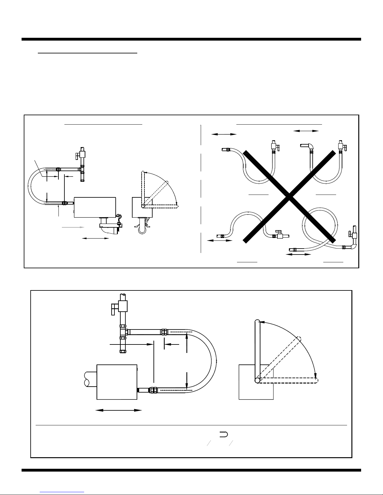
INSTALLATION - Part 4
A - Flexible Gas Connector Line
A Flexible Gas Connector of approved type & size must be installed as shown in Figure 38 and Figure 39, in
one plane, and without sharp bends, kinks or twists. A smooth loop of approximately 12” (30 cm) in diameter is
best. Refer to Figure 38 for examples of correct and incorrect positioning.
Figure 38: Installation Position Instructions
CORRECT POSITIONS INCORRECT POSITIONS
3" (7.62 cm) Max.
Displacement
12"
(30 cm)
1/2" Flexible Gas Connector
Air Flow Direction
Shut-Off Valve
Shut-Off Valve
Heater Movement
Heater Movement
Vertical
(As Shown Below)
Alternate
Positions
Okay
END VIEW
Heater
Movement
WRONG WRONG
Figure 39: Connector Installation Details
(As Shown at Left)
WRONG
Vertical
Heater Movement
WRONG
Heater
Movement
3" (7.62 cm) Max.
Displacement
Heater Movement
WARNING:
Premier VS Infrared Heating System Page 52 June 04, 2014
CONNECTOR MUST BE INSTALLED IN " " CONFIGURATION. USE ONLY THE
36" (90 cm) LONG CONNECTION OF
THAT WAS FURNISHED WITH THIS HEATER.
12"
(30 cm)
1
" OR
2
Alternate
Positions
END VIEW
3
" (12.7 OR 19 mm) NOMINAL ID
4
Okay
Page 53

INSTALLATION – Part 5
Part 5 - Electrical Connections
General Requirements
If electronic components are to be installed in an area that is subject to water (drips, spray, rain etc.) then
sufficient means shall be provided by the Installer to protect the components from water ingress.
Ensure that all Electricity to the Supply locations involved has been ‘disconnected’ and ‘locked out’ as
per local and national safety requirements before proceding with any part of the Electrical installation.
General Wiring
All field wiring and connections must be in accordance with the National Electric Code, ANSI/NFPA 70 in the
US, and the Canadian Electric Code, CSA C22.1 in Canada, and must comply with all local requirements.
All heaters must be connected and electrically grounded in accordance with the National Electric Code,
ANSI/NFPA 70 in the US, and the Canadian Electric Code, CSA C22.1 in Canada, and must comply with all
local requirements.
Thermostats
Preference is to have each Branch as a separate Heating Zone with a separate Thermostat for better control of
heat levels and fuel usage.
Thermostats must be located/ mounted within the operting heat envelope of the Radiant Line Branch being
controlled. Thermostats must be protected / shielded from direct ‘line of sight” with the Radiant Tubing &
Reflectors.
Control Methods & Devices*
1. Single Thermostat: Entire system operates as one Heating Zone, ON or OFF using one Relay to control the
Vacuum Pump, Vacuum Switch and Burner Power.
2. Multiple Thermostats: System Branches operate as multiple individual Heating Zones which can be
separately controlled ON or OFF. Burners are controlled ON / OFF by the Thermostat they are wired /
connected to using one of the following control devices:
a. Relays (Two) - 2 Thermostats - Hardwired control of Vacuum Pump & Burner Power depending on
individual Thermostat status change.
b. Premier Control Panel - up to 6 Thermostats - Local Panel control of Burner Power & Vacuum
Pump with options for response to Thermostat status change.
c. SRP Accu-Rate
TM
(Modulating Control System)- 2 Systems & up to 4 Thermostats per System Remote / Local control of Burner Power & Vacuum Pump (and optional Modulating Dampers) with
options for various Thermostat status change response types.
*Refer to their respective OEM Manual when electrically wiring ALL Control Devices
Premier VS Infrared Heating System Page 53 June 04, 2014
Page 54
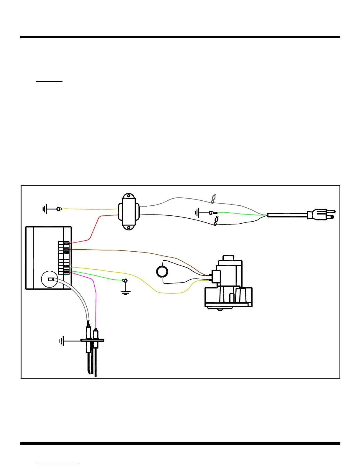
INSTALLATION – Part 5
General Requirements (cont’d)
A - Burners
Maximum current draw is 0.2 A per Burner. Burners operate on 120 VAC, 60 Hz. Internal Burner wiring
between the transformer, gas valve, etc. has been completed by the manufacturer as shown in Figure 40 and
Figure 41 and in the Wiring Diagram located on the inside of the panel door on the Burner Cover. Burners are
connected via a standard three-prong plug (grounded) which has a Power Cord length of 3 ft (90 cm) and
extends from the back of the Burner.
Any repair / replacement of the manufacturer’s wiring must have a minimum temperature rating of at least
105C and supply circuit wiring shall have a minimum size of 18 AWG.
Fenwall
Module
GND
TH
V1
NC
V2
S1
High Voltage
Supression Cable
Yellow
Red
Pink
Figure 40: Burner Wiring Diagram
Transformer
Brown
Green
Spark/Flame Rod
White
Light
Yellow
Black
Green
White
Black
Power Cord
120 V AC, 60HZ
Gas Valve
Premier VS Infrared Heating System Page 54 June 04, 2014
Page 55
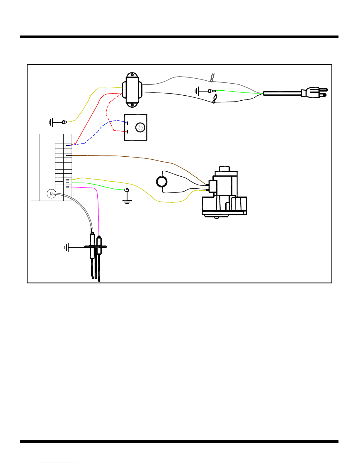
INSTALLATION - Part 5
Figure 41: Burner Wiring Diagram with Optional Delay on make Timer
Yellow
Red
Module
TH
V1
V2
GND
S1
HV
High Voltage
Supression Cable
BLUE
Pink
Transformer
Red
Brown
Green
Black
White
Optional
Delay-on-make
Timer
Light
Yellow
Green
White
Black
Power Cord
120 V AC, 60HZ
Gas Valve
Spark/Flame Rod
B - Fresh Air Blower Interlock
If a Blower is installed to achieve the 40 CPM per 100,000 BTU/hr of Fresh (Combustion) Air Supply
requirement then an ‘interlock’ connection must be made between the Blower and Vacuum Switch (and
therefore the Vacuum Pump).
1. Mount the Vacuum Switch and make the connections to the Blower as required. (See Figure 42 below for
details)
Ensure that field wiring maintains the required clearances when being routed near equipment.
Premier VS Infrared Heating System Page 55 June 04, 2014
Page 56
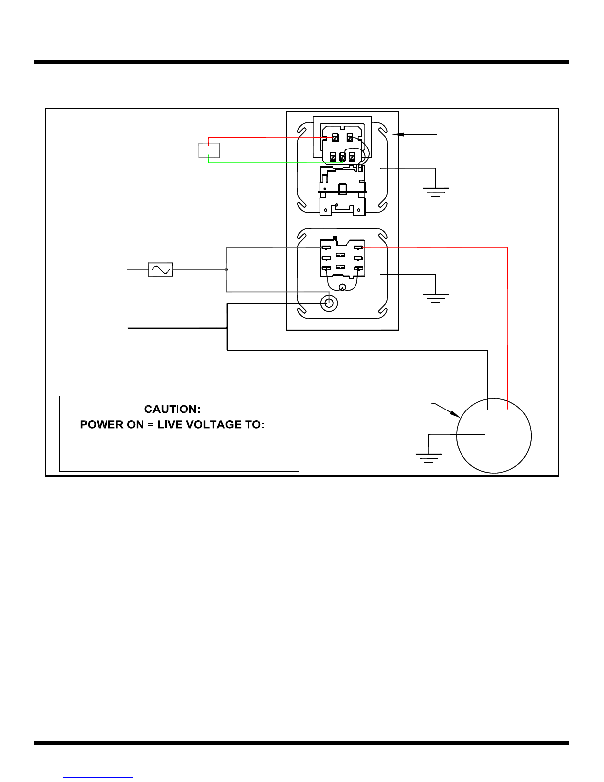
INSTALLATION - Part 5
Figure 42: Fresh Air Blower Connection Diagram
Vacuum Switch
Part # VE007
L1
Supply Voltage
115V, 60 HZ, 15 A
L2
R
G
Black
Black
White
White
SPDT
Relay (P/N: CE046)
COIL
CR
YGW
1
4
3
2
6
5
COIL
1 PH. Fresh Air Blower
115 VAC, 1/3 HP
Transformer
Red
BROWN (2) WIRE
- USE WIRE NUT TO AVOID GROUNDING
& EXPOSURE OF LIVE WIRE
Premier VS Infrared Heating System Page 56 June 04, 2014
Page 57

INSTALLATION - Part 5
C - System Wiring Connections
1. Ensure that field wiring maintains the required clearances when being routed near equipment
2. Mount ALL Electrical components as required by Code(s) and system layout / plan.
Reminder: Ensure that all Electricity to the supply locations involved has been ‘disconnected’ and ‘locked
out’ as per local and national safety requirements before proceding with any part of the electrical
installation.
3. Mount the Thermostat(s) as per plan & as described on Page 53. Wire the Thermostats into the system
Relay(s) / Control Panel as shown in Figure 43, Figure 44 or Figure 45 respectively and according to the
device OEM Manual.
4. Mount the Electrical Power Outlets (120 VAC, 60 Hz, 0.2 A) for each Burner. Outlets are required to be
within reach of the Burner Power Cord while maintaining the minimum clearances around the equipment.
5. Wire the Electrical Power Outlets to the Relay(s) / Control Panel according to the device OEM Manual: as
required for the Heating Zone system Plan/Layout.
6. Mount / position the Vacuum Switch onto the Radiant System as shown in Figure 35. Connect the Vacuum
Switch to the Vacuum Pump and the Relay(s) / Control Panel as shown in Figure 43, Figure 44 or Figure 45
and according to the device OEM Manual.
7. Depending on System layout, wire the Modulating Damper controls to respective panel(s) as per the device
OEM Manual(s) as required.
8. Connect the Electrical Power Supply to the Relay(s) / Control Panel and all other equipment as shown in
Figure 43, Figure 44 or Figure 45 and according to the device OEM Manual.
9. Test all connections / wires as necessary.
DO NOT energize Relay(s) / Control Panel with Electrical Power until it is time to complete the
COMMISSIONING of the System.
10. Confirm that the Vacuum Pump’s impeller rotates in the same direction indicated by the arrow on the pump
scroll. To reverse rotation, see instructions on the motor.
WARNING - DO NOT OPERATE THE VACUUM PUMP WHEN NOT INSTALLED
- Unguarded openings can entangle clothing and severe injury can result
- Unrestricted air flow into Vacuum Pump can cause the motor to overload
Premier VS Infrared Heating System Page 57 June 04, 2014
Page 58
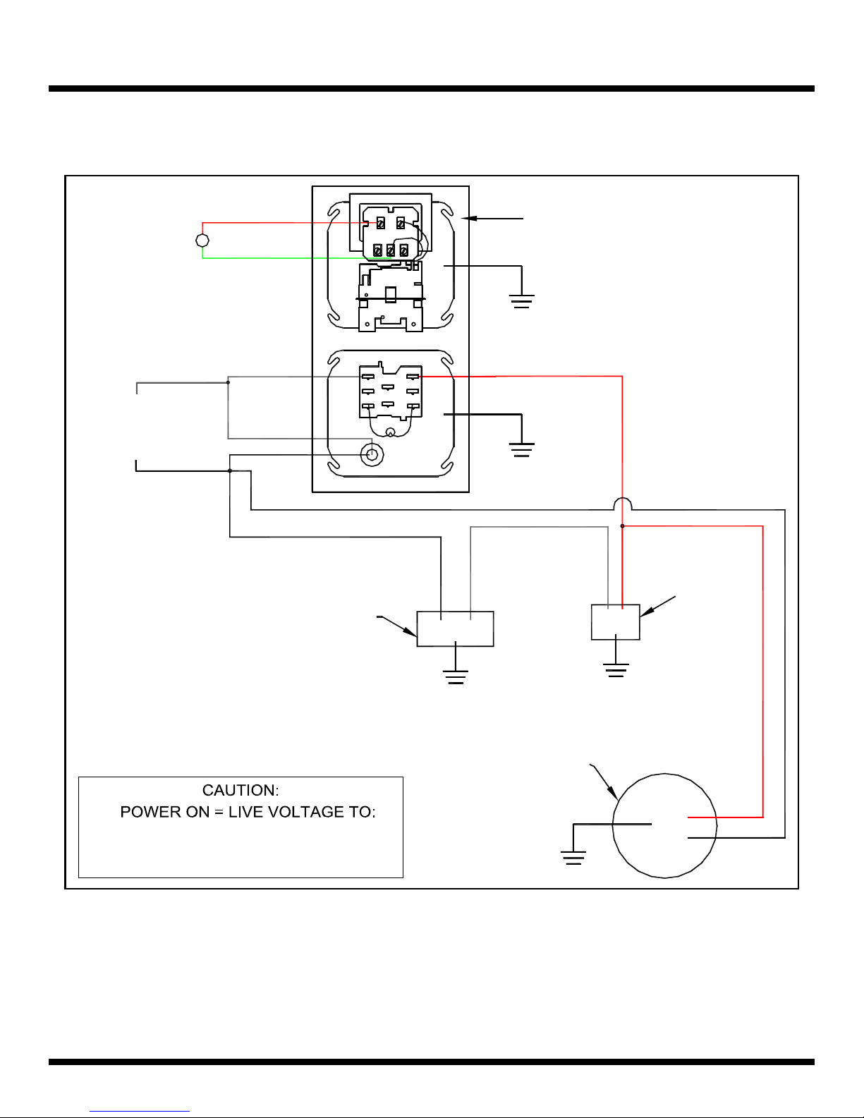
INSTALLATION - Part 5
Figure 43: Single Zone with One Thermostat Wiring Diagram
Thermostat
Black
Supply Voltage
120 V, 60 HZ
15A Circuit
White
SPDT
Relay (P/N: CE046)
WGY
1
4
COIL
RC
2
5
COIL
3
6
R
t
G
Black
Black
White
Transformer
Red
White
White
Neutral
Hot
Red
Vacuum
Switch
VS Burners
(Maximum of 6)
Part #
VE007
BROWN (2) WIRE
- USE WIRE NUT TO AVOID GROUNDING
& EXPOSURE OF LIVE WIRE
Premier VS Infrared Heating System Page 58 June 04, 2014
1 PH. Vacuum Pump Motor
OR 3PH. Motor Starter
Red
White
Page 59
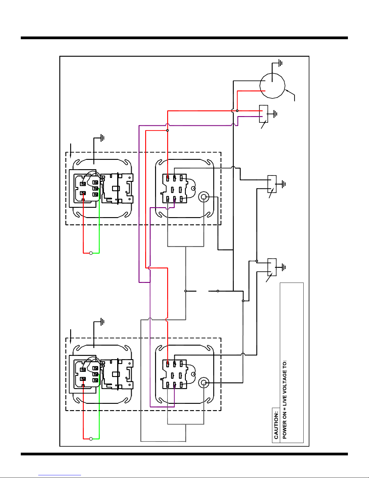
INSTALLATION - Part 5
Figure 44: Two Zones with Two Thermostats - Wiring Diagram
WHITE
RED
PURPLE
RED w/ YELLOW
TRANSFORMER
RELAY (P/N: CE047)
DPDT
R C
RED
PURPLE
RED
3
6
COIL
5
W G Y
RED
2
1
4
COIL
AIR
SWITCH
NEUTRAL
(ZONE 2)
VS BURNERS
OR 3PH. MOTOR STARTER
1 PH. VACUUM PUMP MOTOR
DPDT TRANSFORMER
RELAY (P/N: CE047)
R
t
GW Y
RC
GG
BLACK
120V, 60 HZ
SUPPLY VOLTAGE
WHITE
NEUTRAL
WHITE
(ZONE 1)
VS BURNERS
RED w/ YELLOW
BROWN (2) & YELLOW (5) WIRES
WHITE
THERMOSTAT
(ZONE 2)
PURPLE
BLACK
PURPLE
PURPLE
BLACK
RED
3
2
1
BLACK
6
COIL
5
4
COIL
R
t
(ZONE1)
THERMOSTAT
Premier VS Infrared Heating System Page 59 June 04, 2014
BLACK
BLACK
& EXPOSURE OF LIVE WIRE
- USE SEPARATE WIRE NUTS ON EACH TO AVOID GROUNDING
Page 60
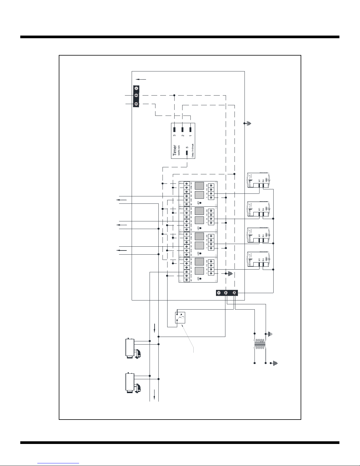
INSTALLATION - Part 5
Figure 45: Control Panel Wiring Diagram (4 Zones)
4 Zones Control Panel
To 24VAC Motor Starter
To 24V Relays
in VS Burners- Zone # 4
To 24V Relays
in VS Burners- Zone # 3
To 24V Relays
in VS Burners- Zone # 2
Relay CE161 and Optional
Fresh-Air Blower Relay CE161
CM
24VAC
Yellow
Red
Blue
VE090
Brown
Red
Brown
Yellow
Blue
Red
CONTROL PANEL
in all burners.
24VAC Isolation
relays are required
Zone #4
Thermostat
Zone #3
Thermostat
Zone #2
Thermostat
Zone #1
Thermostat
Relay Boards
VE093
24 Volt AC
SE010
VE007
At The Pump
N/O Vacuum
Proving Switch
Burners in Zone # 1
To 24V Relays in VS Burners- Zone #1
24 Volt/100VA Transformer,
Mounted Externally
Grounded Supply
115V, 60 Hz
Ground
* This is ONE possible set-up for the Control Panel, other set-ups are available, see OEM Instructions and / or
your SRP Representative for more details.
Premier VS Infrared Heating System Page 60 June 04, 2014
Page 61
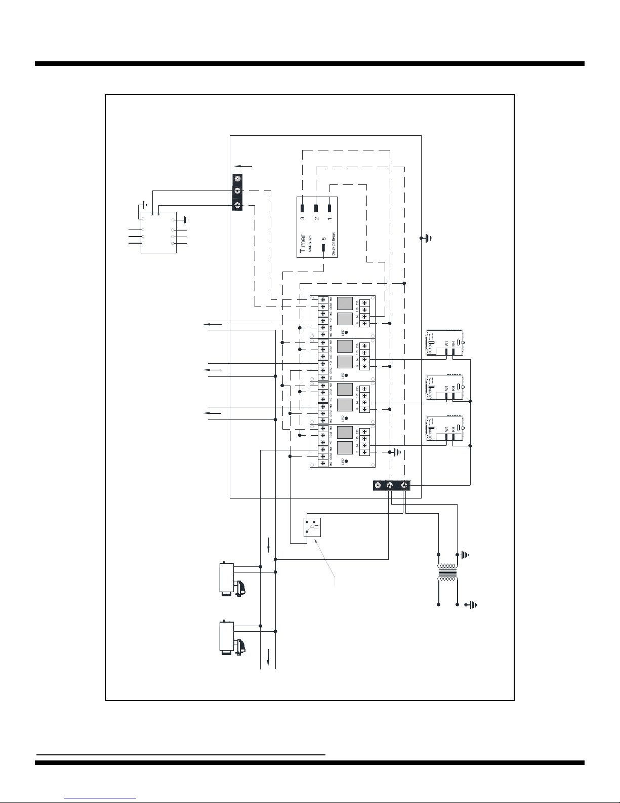
INSTALLATION - Part 5
Figure 46: SRP Control Panel Wiring Diagram with VFD (Optional One Stage, 3 Zones)
Single Stage 3 Zones Control Panel With VFD
Yellow
Red
VE090
Red
Blue
CONTROL PANEL
in all burners.
24VAC Isolation
relays are required
To Vacuum Pump
VE035 -- VFD for Pump-B
VE034 -- VFD for Pump-A
To DI1 & CM Of VFD
CM
DI1
DI1
CM
L3
T3T2T1
AC Drive
GS1
L2
SUPPLY
L1
Green
Black
Brown
To 24VAC Optional
Fresh-Air Blower Relay CE161
To 24V Relays
in VS Burners- Zone # 3
To 24V Relays
in VS Burners- Zone # 2
Zone #3
Brown
Yellow
Blue
Relay Boards
VE093
VE007
At The Pump
N/O Vacuum
Proving Switch
Burners in Zone # 1
Red
24 Volt AC
SE010
Mounted Externally
24 Volt/100VA Transformer,
Grounded Supply
115V, 60 Hz
Thermostat
Zone #2
Thermostat
Zone #1
Thermostat
Ground
* This is ONE possible set-up for the SRP Control Panel with a Variable Frequency Drive (VFD), other set-ups
are available, see OEM Instructions and / or your SRP Representative for more details.
NOTE: VFD is used for a single speed motor control only
Premier VS Infrared Heating System Page 61 June 04, 2014
To 24V Relays in VS Burners- Zone #1
Page 62
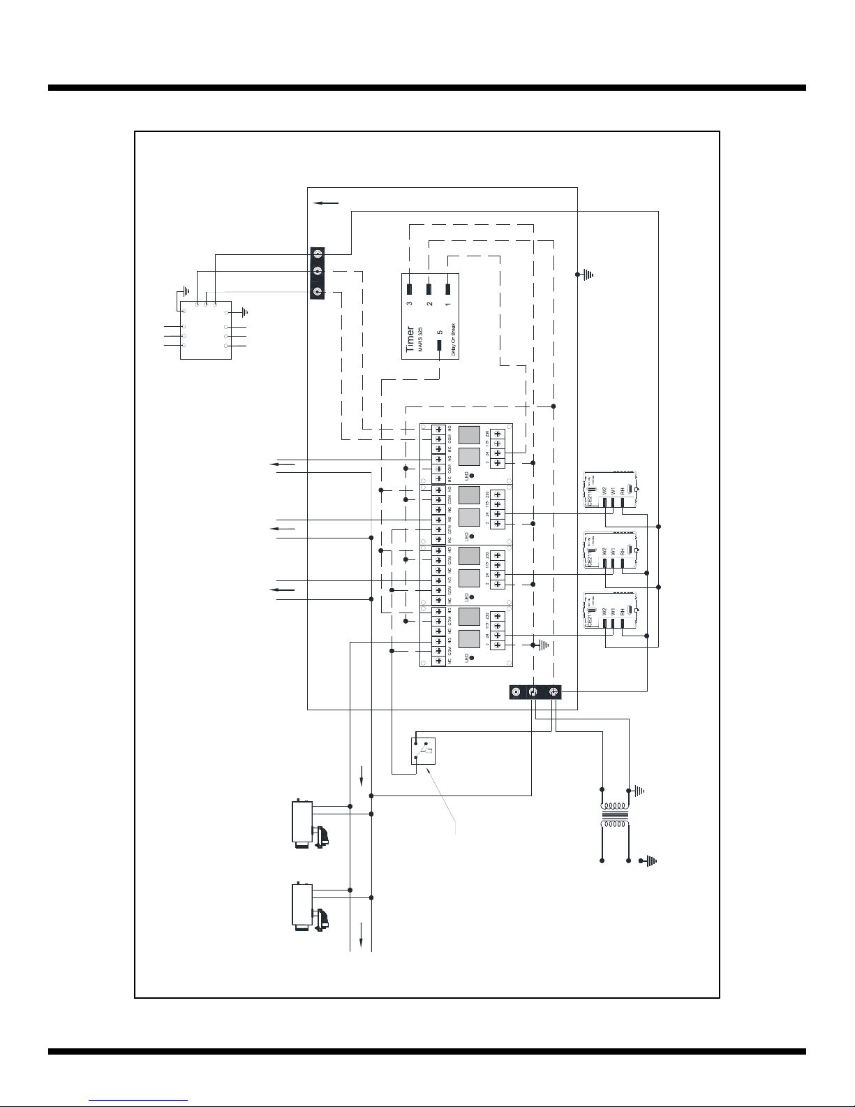
INSTALLATION - Part 5
Figure 47: SRP AccuRateTM Wiring Diagram with VFD (Optional Two Stage, 3 Zones)
Two Stage 3 Zones Control Panel With VFD
VE035 -- VFD for Pump-B
VE034 -- VFD for Pump-A
DI1
CM
DI2
T3T2T1
L2 L3
AC Drive
GS1
To Vacuum Pump
SUPPLY
L1
To 24VAC Optional
Fresh-Air Blower Relay CE161
To 24V Relays
in VS Burners- Zone # 3
To 24V Relays
in VS Burners- Zone # 2
CM DI2
DI1
Black
To DI1, DI2 & CM Of VFD
Green
Brown
Blue
VE090
Yellow
Red
Red
Blue
Red
Yellow
CONTROL PANEL
24VAC Isolation
relays are required
Zone #3
Thermostat
Zone #2
Thermostat
Zone #1
Thermostat
in all burners.
Relay Boards
VE093
24 Volt AC
SE010
VE007
Burners in Zone # 1
To 24V Relays in VS Burners- Zone #1
N/O Vacuum
Proving Switch
At The Pump
Mounted Externally
24 Volt/100VA Transformer,
Grounded Supply
115V, 60 Hz
Ground
* This is ONE possible set-up for the SRP Control Panel with a Variable Frequency Drive (VFD), other set-ups
are available, see OEM Instructions and / or your SRP Representative for more details.
Premier VS Infrared Heating System Page 62 June 04, 2014
Page 63

COMMISSIONING
Part 1 - Installation Checklist
Before proceeding with the start-up of the system, review the list of items below to ensure proper operation.
Close all open ended “S” hooks and turnbuckles to avoid unlocking chain with inadvertent contact
Verify that the Burners are correct for the fuel being burned. The rating plate listing this information is
located on the Burner housing, check this against your site plans.
Burners are position dependent. For proper operation, ensure that the Burner labeled as ‘No. 1’ on the
housing is located at the end of each Radiant Branch. Subsequent Burners in each Branch must be
positioned sequentially.
Burners should be mounted with the Burner casting as far back in the Tube opening as possible. Ensure
that little or no Tube is in view thru the viewing window.
Ensure that the End Vent Cap is oriented with the ¼” test hole at the 12 o’clock position and that it has
been secured to the end of each Branch with a #8 x 3/8” screw.
If you have both hot rolled Tube (black & shiny) and heat-treated aluminized steel Tube (matte gray),
ensure that the heat-treated aluminized Tube is used in the Tailpipe section of the system, and used in the
10 ft (3 m) following all Burners with a rating of 150,000 BTU/HR or higher.
Ensure that Tubes are fully inserted in the Couplings and tightened with band clamp hardware at the 10 or
2 o’clock position. Tighten band clamps alternately to prevent buckling of the Coupling sleeve.
Ensure that each Branch has a Damper Coupling at the end of the Radiant length, as well as one at the
Vacuum Pump. If the system is symmetrical, one Damper along the Common Tailpipe may be used.
Single Rate Systems will use standard Manual Dampers while Modulating Rate Systems will use
Motorized Dampers.
Ensure that Reflectors are properly overlapped and that every second overlap joint is screwed together, as
shown in Figure 9. The remaining joints are left loose. This will allow the Reflectors to ‘telescope’ with
the thermal expansion of the System.
Visually confirm that the Vacuum Pump’s impeller rotates in the same direction indicated by the arrow on
the pump scroll. To reverse the rotation, see instructions on the motor.
Ensure that EACH Flexible Gas Connector is of sufficient size for the desired Burner rate and is installed
in a smooth arc with no kinks. For Burners firing at 150,000 BTU/hr and higher ¾” dia. x 36” Gas Flex
Connector is required.
Purge Gas Lines of all air.
Verify the Wiring & that the Electrical Power Supply is connected but remains turned OFF.
Premier VS Infrared Heating System Page 63 June 04, 2014
Page 64

COMMISSIONING
Part 2 - Initial System Power Test
With the individual gas valves to each burner ‘Shut off’ perform the following:
1. Ensure Gas Supply is turned OFF. (Open main gas valve and ensure that no gas is flowing through the gas
meter [dial test].)
2. Verify that lock-up gas pressure is not above 14 in. W.C.
3. Set all thermostats below room temperature and turn ON main power – no part of the System should be
energized.
4. Check each Radiant Branch in each Zone in sequence by turning up the appropriate Thermostat. In each
case the Vacuum Pump should turn on and after the pre-purge time, the Burners in that Zone should attempt
to light.
5. Troubleshoot as necessary to get the System operational. (See the Trouble-Shooting section of this manual
for more detailed information & helpful notes.)
Premier VS Infrared Heating System Page 64 June 04, 2014
Page 65

COMMISSIONING
Part 3 - Balancing the System Vacuum
NOTE: The Premier VS burner is a variable rate appliance. Vacuum Pump setting must be accurately adjusted
to ensure Burners are operating at the specified design input.
1. Turn ON the Electrical Supply but NOT the Gas Supply (remains turned OFF).
2. Allow the system to run without Burners operating.
3. With a manometer check the vacuum at the End Vent Cap of the longest Branch. (Refer to Figure 48 for
manometer positioning details.)
4. Adjust the Damper that is installed in the Tailpipe of the same Branch to obtain the vacuum readings
according to Table E below. (In Systems that are “Symmetrical” there will be only one Damper along the
Common Tailpipe.) The setting maybe within +0.75 to +0.50 in. W.C. at this time. Mark the Damper
positions for future reference.
5. Proceed similarly until each individual branch in the system is balanced / adjusted.
6. Shut down the System.
7. Turn ON the Gas Supply.
8. Turn up the Thermostat(s) to start the System and let it run (with Burners operating) for at least 30 minutes.
9. With a manometer check the vacuum at the End Vent Cap of the longest Branch. (Refer to Figure 48 for
manometer positioning details.)
10. Adjust the Dampers again (Caution: dampers are now hot adjust with caution) as required to obtain the
vacuum readings within +0.1 to -0.2 in. W.C. of the settings in Table E. The Burners in this Branch should
now be firing at the appropriate rate.
11. Proceed similarly until each individual Branch in the System is balanced / re-adjusted.
12. Mark the Damper position and lock in place when the System has been balanced. (Lock in place by putting
a screw through the handle to hold it against the Sleeve / Tube.)
13. Turn the Thermostat(s) down again to shut off the System.
Note: An End Vent Vacuum which is intermediate to (between) those shown will result in rates intermediate
and proportional to those which are listed.
Note: Vacuum settings and rates apply regardless of the number of Burners being used in the System Branch.
Your System is now ready for use.
Premier VS Infrared Heating System Page 65 June 04, 2014
Page 66
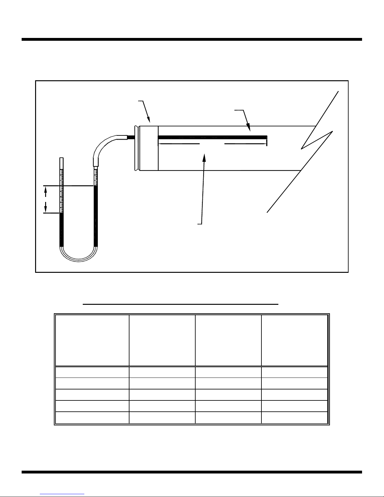
COMMISSIONING
Figure 48: Manometer Placement Diagram
End vent cap
0.25" O.D.
Ridgid Tubing
12"
Insert manometer 12"
H
from the end of the End
Vent Cap in order to
establish recommended
end vent vacuum settings
H = Inches W .C.
(see Table B)
Table E: Vacuum System Settings for Relative Burner Rates
Radiant
Branch
End Vent
Vacuum
[Inches W.C.]
1.7 150 000 120 000 120 000
2 175 000 130 000 130 000
3 200 000 165 000
3.6 225 000
4.5 250 000
Premier VS Infrared Heating System Page 66 June 04, 2014
Burner
Position
(Flow Plate)
No. 1 Rate
[MBTU/hr]
Burner
Position
(Flow Plate)
No. 2 Rate
[MBTU/hr]
Burner
Position
(Flow Plate)
No. 3 Rate
[MBTU/hr]
Page 67

Manual Set-Up
1. Set the ambient temperature to be maintained at / by each Thermostat.
2. Ensure Electrical Power and Gas Supply are turned “ON”
Automatic Operating Sequence
Start-up
1. Thermostat calls for heat and energizes the transformer relay.
2. Transformer relay contacts close and the Vacuum Pump motor is energized.
OPERATION
3. If the Vacuum Switch finds no fault, power is supplied to all the Burners in the Zone(s) in which the
Thermostat(s) are calling for heat.
4. At the Burner, the control module waits for the pre-purge period and then opens the fuel valve and the spark
igniter is energized. Time delay in the control module causes the Burners to light sequentially.
5. When the flame is established, the flame sensor signal returns to the control module and the ignition spark
ceases.
6. If the flame is not established, the control module will re-try the ignition cycle again in 30 seconds.
7. Should ignition continue to fail, the control module will make 3 ignition attempts every hour.
8. If it does not, or if it continues to “not establish a flame”, Trouble-Shoot to find the cause.
9. System operates until Thermostat(s) temperature setting is reached.
Shut-down
1. When the Thermostat has been supplied sufficient heat, its contacts open and de-energize the transformer
relay.
2. The contacts of the transformer relay open and Electrical Power to the Burners and Vacuum Pump is
disconnected.
3. A post purge cycle can be provided when a Control Panel is supplied.
4. System remains ‘OFF’ until ambient temperature falls below the Thermostat(s) setting.
5. System cycles through Steps 1 to 10 on a continuous basis until Power is turned OFF.
Premier VS Infrared Heating System Page 67 June 04, 2014
Page 68

MAINTENANCE & TROUBLE-SHOOTING
General Safety Reminders
Ensure Gas Supply and Electrical Power are shut OFF before commencing maintenance work. Exception:
Checking ignitor flames will require the system to be operational.
Keep area clear and free from combustible materials, gasoline and other flammable vapors and liquids.
Caution: Label All Wires Prior To Disconnection When Servicing Controls. Wiring Errors can cause
improper and dangerous operation.
Verify proper operation and set-up (as listed in the Commissioning section) after servicing.
Annual Maintenance Recommendations
Annual maintenance, prior to the heating season (Fall / Winter) is recommended.
Part 1: Each Burner
1. Remove Burner and inspect burner face for soot or cracks.
2. Visually inspect electrode. Replace if there is excessive oxidation, erosion or cracks in the ceramic
insulators. Set spark gap at 0.125” (3.175 mm) and clean the electrodes.
3. Verify that flame observation glass is clean, free of cracks and airtight.
4. Inspect air filter. Change as necessary.
5. Observe each flame through the flame sight glass.
6. Flame may flutter once or twice at ignition but should settle promptly.
7. Flame should extend straight out from Ignitor
8. Sense rod (and ignitor) will glow bright red-orange on all except No.1 Burners.
Note: Dirty air filters will restrict combustion air flow into the burner housing, creating a slight
negative pressure environment for the zero governor (and other controls). Consequently, while flame
characteristics and balance will not change appreciably, overall burner rate will decline. Very dirty
filters will cause the flame to become more rich (yellow and soft). Filters can be cleaned once with
reverse air pressure, but it is generally more cost effective to merely replace them.
For VS Air Filter includes frame (Bulk Qty. 20) use part No. VH001B
For VS Filter Media Kits (Bulk Qty 24) use part No. VH053B
(Overall System maintenance requirements are found on the next page.)
Premier VS Infrared Heating System Page 68 June 04, 2014
Page 69

MAINTENANCE & TROUBLE-SHOOTING
Part 2: The Vacuum Settings
1. If the Vacuum is too low, inspect the Flexible Boot Connectors on the Inlet and Outlet of the Vacuum Pump
if the Vacuum for tight connections, leaks, damage, kinks, etc.
Part 3: The System
1. Inspect the Common Tailpipe and Vent Pipe for soot or dirt, clean as required to avoid obstructions.
2. Check that Flexible Boot Connectors are without cracks, kinks or leaking connections.
3. Ensure that the Vacuum Pump and motor mounting bolts are tight.
4. Make a visual inspection (without dismounting) of the Vacuum Pump impeller.
5. Clean the Condensate Trap and ensure that all piping to / from the Condensate Trap allows free flow of
fluid.
6. There should be no sound of leaking air around any of the various gaskets or connections.
7. Make spot checks of the interior of the Radiant Line Tubes for soot or obstructions, clean as required.
Premier VS Infrared Heating System Page 69 June 04, 2014
Page 70

MAINTENANCE & TROUBLE-SHOOTING
Trouble-Shooting
Vacuum Pump
Vacuum Pump Fails To Run
1. Check that a Thermostat is calling for heat.
2. Check the main Electrical Power Supply, fuses or breakers.
3. Check for power to the Control Panel or Relay.
Vacuum Pump Runs, But Little to No Vacuum
1. Check the direction of the impeller rotation.
2. Are the End Vent Caps installed in all of the Branches?
Vacuum Pump Runs, But No Power to Burners
1. Check the Vacuum Switch.
2. Check voltage to Burner terminals.
3. Check Relay.
4. Check individual Burner control.
Burners
No Power to Burner
1. Check if correct Thermostat is calling for heat.
2. Check for 120VAC supply at Burner.
No Gas Supply
1. Ensure manual supply valve to the System is turned ON.
2. Ensure gas valve knob on Burner gas control is ON.
3. Check for 24V across valve terminals during ignition trial time.
Burner Does Not Light
1. Ensure spark is present during ignition trial.
2. (If no, check control module, check for cracked ignitor insulation.)
3. Ensure there is gas flow during ignition trial.
4. Purge gas lines.
5. Ensure Filter is not obstructed.
Burner Does Not Stay Lit
1. Check ground wire from ignitor for continuity.
2. Measure flame signal current, it should be above 5 A - DC.
3. Regulator adjustment may be necessary.
4. Ensure Filter is not obstructed.
Premier VS Infrared Heating System Page 70 June 04, 2014
Page 71
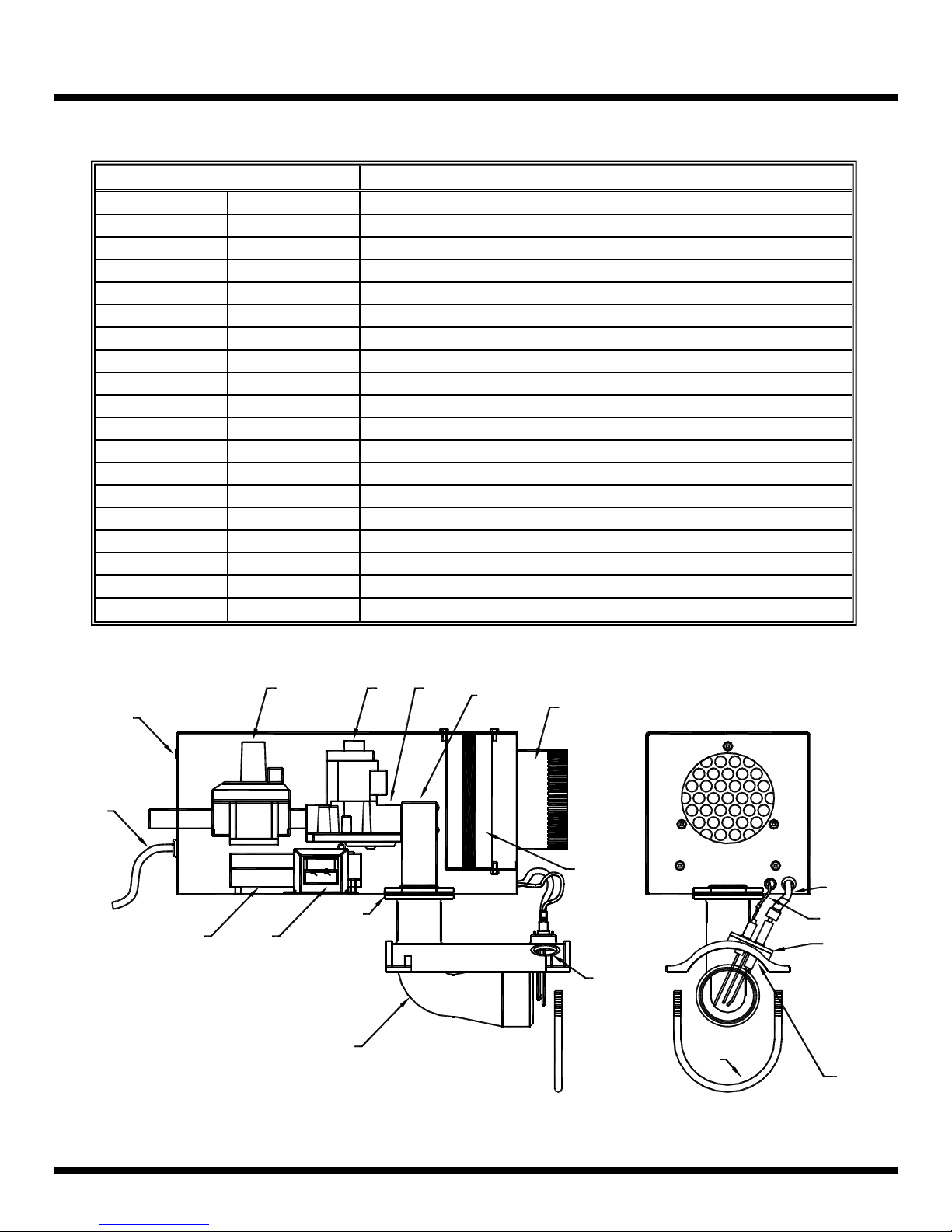
PARTS
Table F: Burner Parts List
Item No. Part No. Description
1 VG0 10 ZERO GOVERNOR, MAXITROL R-500Z
2 VG009 GAS VALVE, HONEYWELL 8205M
3 VH002 VALVE GA SKET
4 VG001 MIXING CHAMBER
5 VS022 COM B USTION AIR ADA PTOR AND GASKET (AIR)
6 VH001 COMBUSTION AIR FILTER
7 CH007 VALVE TRAIN GASKET/BURNER MOUNT
8 VG0 16 BURNER HEA D ASSEMBLY (ELECTRODE INCL UDED)
9 CE008 TRANSFOR MER
10 CE05 6 CONT R OL M ODULE , FEN WAL
11 CE010 POWER CORD
12 CE057 OPERATOR INDICA TOR LIGHT (ROUND)
13 VH003 BURNER MOUNTING GA SKET
14 VH004 M OUNTING U-BOLTS
15 CE036 SENSE WIRE
16 CE006 IGNITION WIRE (12 INCH)
17 VE002 ELECTRODE ASSEM BLY
18 VH005 ELECTRODE ASSEMBLY GASKET
19 CH011 FLAME SIG HT WINDOW
23
7
8
4
5
6
16
15
17,18
19
14
13
11
12
10
1
9
Premier VS Infrared Heating System Page 71 June 04, 2014
Page 72
PARTS
Part No. Description Part No. Description
V SN1 PREMIER VS BU RNER #1 N AT VSP1 PREMIER VS BURNER #1 LPG
V SN2 PREMIER VS BU RNER #2 N AT VSP2 PREMIER VS BURNER #2 LPG
V SN3 PREMIER VS BU RNER #3 N AT VSP3 PREMIER VS BURNER #3 LPG
Table G: Burner Part Numbers
Table H: Gas Connection Replacement Part Numbers
Part No. Description
CG022 GAS FLEX CONNECTOR - 36" x 1/2" dia.
CG024 GAS FLEX CONNECTOR - 36" x 3/4" dia.
CG011 SHU T OFF VA LVE - for gas flex (1/2")
CG028 SHU T OFF VA LVE - for gas flex (3/4")
Table I: Vacuum Pumps - Main Part Numbers
Part No. Description
V H010 PUM P MOUNTING PKG .
VS010 VI BRATION BOOT PKG - 4" for vacuum pump
VS048 VI BRATION BOOT PKG - 6" for vacuum pump
VE020 V ACUUM PUMP A w/ below:
VE032 MOTOR - 0.75 HP, 110/220 V, 1 PH
VE024 V ACUUM PUMP A w/ below:
VE039 MOTOR - 0.75 HP, 208/230/460 V, 3 PH
VE021 VACUUM PUMP B w/ below:
VE030 MOTOR - 1.50 HP, 208/230/460 V, 3 PH
VE023 VACUUM PUMP B w/ below:
VE031 MOTOR - 1.50 HP, 575 V, 3 PH
VE025 VACUUM PUMP B w/ below:
VE049 MOTOR - 1.50 HP, 115/230 V, 1 PH
Table J: Optional Wall Vent Terminal Part Numbers
Part No. Description
CT011 VENT TERM INAL 4" - Exterior Wall Flue (Pump A)
CT044 VENT TERM INAL 6" - Exterior Wall Flue (Pump B)
CS006 WALL THIMBLE 4" (Pump A)
CS033 WALL THIMBLE 6" (Pump B)
Premier VS Infrared Heating System Page 72 June 04, 2014
Page 73
Table K: Main System Component Parts List
Part No. Description Part No. Description
SPECIALTYTUBINGCOMPONENTSCOMMONCOMPONENTS
VT001 VSCOMBUSTIONTUBE,4"OD CT002 TUBE,4"ODHR
CT001 TUBE,4"OD,HEATTREATEDALUM. CT012 TUBE,4"ODALUMINIZEDNHT
CT010 ELBOW,90DEG,4"OD CT055 ELBOW,4"ODx45DEGREES
CT020 U‐TUBE,4"ODon10"RADIUS(ROUND) CT050 TEE,4"DOUBLESWEPT
CT021 TEEFITTING,4"ODSQUARE CT051 TEE,4"SINGLESWEPT
CT022 CROSS,4"O.D.ALUMINIZED VT001S SHORTCOMBUSTIONTUBEVS
CR010 COUPLINGASS'Y4"ALUMIN IZED
VS016 END
CH0 10 TURNBUCKLE CT040 ELBOW,90DEG,5"OD
CR003 HAN GER,TUBE&REFLECTOR CT05 2 TEE,5",SINGLESWEPT
CR024 REFL.BRACKET&CLIPSET CT039 TEEFITTING,5",DOUBLESWEP T
CR001 REFLECTOR124" CT056 CROSS,5"OD, SQUARE
CR002 ENDCAP CT078 CROSS,5"OD,DOUBL ESWEPT
CS005 4"AIRINLETHOOD CT041 REDUCER6"‐5"w/PSNIPPLE
CR015 DAMPERCOUPLING,4"‐MANUAL CT042 REDUCER,5"‐4"ALUMIN IZED
CR025 HAN GERSTRAP,4"ODTAILPIPE CR028 COUPLING5"DIA
VH044 CONDENSA TETRAPASSEMBLY CR070 DAMPERCOUPLING,5"‐MANUA L
OPTIONALSIDE SHIELDEQUIPMENT
CR039 REFLECTORKIT‐MI TERED90DEGREE
VR003 BURNERREFLECTORKIT VT003 S/SCOMBUSTIONTUBEVS
CR019 SIDEREFLECTOR CR005 S/SCOUPLINGASS'Y,4"
CR016 BRACKETASS'Y(forSI DESHIELD) CR027 S/ SCOUPLINGLINER
CR035 RETAINERCLIP‐SIDESHI ELD CR047 S/SDAM PERCOUPLING‐MANUA L
VENTCAP CT038 TUBE,5"OD
CR029 HAN GERSTRAP‐5"TAILPIPE
SideReflecterComponents
BottomShieldComponents
CT030 S/SRADIANTTUBE
CR032 S/SREFLECTOR
PARTS
5"Tailpipe
StainlessSteel(S/S)
CR018 BOTTOMREFLECTOR/SHIELD CR033 S/SSIDERE FLE CTOR
CR017 SUPPORTASS'Y(forBOTTOMSHIELD)
DECO‐GRILLEComponents(Suspended
CR051 DECORATIVEGRILLE15"x60"x.5" CT033 TUBE,COATEDINSIDE&OUT
CR052 DECOGRILLESUPPORT60" VT004 COMBUSTION TUBEVSCOATEDINSIDE
CR053 DECOGRILLECROSSSTRAP15" V T005 COMBUSTIONTUBEVSCOATEDIN&OUT
CR054 DECOGRILLEENDANGLE15" CT034 ELBOW90DEGREE,COATEDINSIDE
DECO‐GRILLEComponents(SuspendedCeiling)
CR026 DECOGRILLEPANEL24"x
CS059 DECOGRILLESIDESHIELD CT037 TEE,4"SQUARECOATEDINSIDE&OUT
CR053 DECOGRILLECROSSSTRAP15"
CR054 DECOGRILLEENDANGLE15" VT013 MOTORIZEDDAMPER4"Dia.
CS027 T‐BARSHIELD VT014 MOTORIZEDDAMPER5"Dia.
Premier VS Infrared Heating System Page 73 June 04, 2014
CoatedTubes
fromHeater)
48" CT036 TEE,4"SQUARECOATEDINSIDE
CT032 TUBE,
CT035 ELBOW90DEGREE,COATEDINSIDE&OUT
MODULATINGSYSTEMCOMPONENTS
COATEDINSIDEONLY
Page 74
WARRANTY
PREMIER VS
VACUUM SERIES INFRARED SYSTEM
The Manufacturer warrants to the original owner that the product will be free of defects in material and
workmanship as described below.
VS Vacuum System Components
Control Panel
Vacuum Pump
Burner Electrical Components
Cast Iron Burner Head
Hot Rolled Heat Exchanger
Aluminized Heat Exchanger
Hot Rolled Heat Exchanger with Control Panel
Aluminized Heat Exchanger with Control Panel
Tailpipe – Aluminized / Coated (per minimum design length)
Warranty Period (Years)
1 3 5 7 10
The Manufacturer’s obligation under this warranty is limited to repair or replacement, F.O.B. its facility, of the
defective part. In the case of replacement parts, the warranty period shall be the longer of the original warranty
or a period of 12 months from date of purchase. In no event shall the manufacturer be liable for incidental
expense or consequential damages of any kind.
This warranty does not cover any shipping, installation or other labour costs incurred in the repair or
replacement of the product. No materials will be accepted for return without authorization.
This warranty will not apply, if in the judgment of the Manufacturer, the equipment has been improperly
installed, unreasonably used, damaged, or modified.
This warranty will not apply to damage to the product when used in corrosive atmospheres and in particular
atmospheres containing halogenated hydrocarbons. No person is authorized to assume for the Manufacturer
any other warranty, obligation or liability.
THE REMEDIES PROVIDED FOR IN THE ABOVE EXPRESS WARRANTIES ARE THE SOLE AND
EXCLUSIVE REMEDIES. NO OTHER EXPRESS OR IMPLIED WARRANTIES ARE MADE
INCLUDING, BUT NOT LIMITED TO, ANY IMPLIED WARRANTY OF MERCHANTABILITY OR
FITNESS FOR A PARTICULAR USE OR PURPOSE.
Premier VS Infrared Heating System Page 74 June 04, 2014
 Loading...