

Superior Radiant LA series, LX series, LXR series Installation, Operation And Service Instructions
Page 1
Series LA/LX/LXR Infrared Heater
Installation, Operation and Service Instructions
FOR YOUR SAFETY FOR YOUR SAFETY
If yo u s me ll ga s:
1. Open windows
2. Don’t touch ele ct rical switches
3. Extinguish any open flame
4. Immediately ca l l your ga s supplier
CONSIGNES DE SECURITE
Si vous sentez une odeur de gaz:
1. Ouvrez les fenetres
2. Ne touchez pas aux interupteurs
electriques
3. Eteignez tout flamme nue
4. Contactez immediatment votre
fournisseur de gaz
Read and thoroughly understand these instructions before attempt ing any insta llation.
Retain this manual for refe re nce.
WARNING
Improper installat ion, ad just ment, alteration, service or maintenance can cause injur y, death or property
damage. Read the installation, operation and service instructions thoroughly before installing or
serv icing this equip ment.
Installer
Owner
Do no t st ore or use gasoli ne or other
flammable vapo rs and liquids in t he
vicinity of this or any other appliance.
CONSIGNES DE SECURITE
Il est interdit d‘utiliser des liquides
inflammables ou degageant des
vapeurs inflammables, a proximites de
to ut app areil fonctionnent au gaz.
23-428 Millen Road, Stoney Creek, Ontario L8E 3N9
Superior Radiant Products
www.superiorradiant.com
Page 2
CAUTION: FIRE OR EXPLOSION HAZARD
Maint a in c lear anc e t o co mbustib le co ns tr uct ion s a s fur t her spec if ied in t his ma nua l. Fa i lure
to do so could result in a serious fire hazard. Heaters should not be located in hazardous
atmospheres containing flammable vapors o r combustible dusts. Signs should be provided in
storage areas specifying maximum safe stacking height.
CAUTION: MECHANICAL HAZARD
This equipment expands and contracts with each operating cycle. The gas connection,
suspe ns ion ha rdw are a nd t he inst a llat ion it sel f mu st sa fely a llow th is mo veme nt. Failu re t o
do so could result in serious fire or explosion hazard.
CAUTION: FIRE OR EXPLOSION HAZARD
This heater is equipped with an automatic ignition device. Do not attempt to light t he burner
by hand. Failure to comply could result in a serious fire and personal injury hazard.
CAUTION: MECHANICAL HAZARD
Do not use high pressure (above 1/2 psi) to test the gas supply system with the burners
connected. Failure to do so could result in damage to the burner and its control components
requiring replacement.
CAUTION: SERVICE LIFE RISK
Do not install equipment in atmospheres containing halogenated hydrocarbons or other
corrosive chemicals. Failure to do so may lead to premature equipment failure and
invalidation of the warranty. Additionally, it is r ecommended that the equipme nt be installed
with a slope downward and away from the burner of ¼" inch in 10' feet to allow start-up
condensate drainage.
Page 3

Table Of Cont en t s
INTR O D U CT ION ............................................................................................................................... 2
Importan t ................................................................................................................................................ 2
Installation Codes .................................................................................................................................... 2
General Installation and Gas Codes ............................................................................................. 2
Aircraft Hangar Installation ........................................................................................................ 2
Public Garage Installation ........................................................................................................... 2
Gas Supply Lines ........................................................................................................................ 3
Electrical .................................................................................................................................... 3
Venting ...................................................................................................................................... 3
GENERAL SPECIFICATIONS.......................................................................................................... 3
Gas Supply.............................................................................................................................................. 3
Inlet Pressures ............................................................................................................................ 3
Manifold Pressu res ..................................................................................................................... 3
Inlet Connections ........................................................................................................................ 3
Electrical Supply ..................................................................................................................................... 3
Flue and Outside Air Connection ............................................................................................................. 3
DIMENSIONAL CHARTS ................................................................................................................. 4
CONFIGURATIONS........................................................................................................................... 5
CLEARANCE TO COMBUSTIB LES ................................................................................................ 6
Clearance to Combustibles Materials ....................................................................................................... 7
INSTALLATION DETAIL ................................................................................................................. 8
Installation Sequence............................................................................................................................. 11
VENTING / COMBUSTION AIR DUCTING ..................................................................................20
General Requirements ........................................................................................................................... 20
Un-Vented Operation ............................................................................................................................ 20
Vented Operation .................................................................................................................................. 21
Horizontal Venting ................................................................................................................... 21
Vertical Venting ....................................................................................................................... 21
Common Roof Venting ............................................................................................................. 22
Combustion Air Supply (Optional) ........................................................................................................ 23
Outdoor Installation .............................................................................................................................. 23
GAS PIPING .......................................................................................................................................24
General Requirements ........................................................................................................................... 24
ELECTRICAL WIRING ...................................................................................................................25
General Requirements ........................................................................................................................... 25
BURNER OPERATION .....................................................................................................................26
Starting Sequence of Operation ............................................................................................................. 26
Maintenance.......................................................................................................................................... 26
TROUBLESHOOTING .....................................................................................................................27
Blower motor Fails to Run .................................................................................................................... 27
No Gas Supply ...................................................................................................................................... 27
Burner Does Not Light .......................................................................................................................... 27
Burner Does Not Stay Lit ...................................................................................................................... 27
Troubleshooting Chart ........................................................................................................................... 28
REPLACEMENT PARTS ..................................................................................................................29
WARRANTY ......................................................................................................................................31
Series-LA/LX/LXR Page 1 6/15/2010
Page 4
Introduction
Superior Radiant Products is a company in the infrared heating industry founded on the principles of
product quality and customer commitment.
Quality commitments are evidenced by superior design, a regard for design detail and an upgrade of
materials wherever just ifiable.
Customer commitment is apparent thro ugh o ur ready responses to market demands and a never ending
training and service support program for and through our distributor network.
Superior Radiant offers its 15 years of infrared expert ise in a cost effective unitary heat er design as
culminatio n of t ha t co mmitment. Series LA/LX/L X R models are field ass emb led, low inten sit y infrared
heaters that are easy to install and maintain, and which were engineered w ith significant input from our
customers. They are designed to prov ide economical operation and trouble-free service for years to
come.
Important
These instructions, the layout drawing, local codes and ordinances, and applicable standards such as
apply to gas piping and electrical wiring comprise the basic information needed to complete the
installation, and must be thoroughly understood along with general building codes before proceeding.
Only personnel who have been trained and understand all applicable codes should undertake the
installation. SRP Represe nt atives are Factory Certified in the service and application of this equipme nt
and can be called on for helpful suggestions about installation.
Installation Codes
Installations must co mply with local building codes, or in their absence, t he latest edit ion of the national
regulations and procedures as listed below.
General Installation and Gas Code s
Heaters must be installed only for use with the type of gas appearing on the rating plate, and the
installa tion mus t conform to the National Fuel Gas Code, ANSI Z223.1 (NFPA 54) in the US and
CAN/CGA B149.1 and B149.2 Installation Codes in Canada.
Aircraft Hangar Installation
Installation in aircraft hangars must conform to the Standard for Aircraft Hangars, ANSI/NFPA 409 in
the US and CAN/CGA B149.1 and B149.2 Installation Codes in Canada.
Public Garage Installation
Installation in public garages must conform to the Standard for Parking Structures, NFPA-88A or
Standard for Repair Garages, NFPA 88B, in the US and CAN/CGA B149.1 and B149.2 Installation
Codes in Canada.
Parking Structures
Technical requirements are o utlined in ANSI/NFPA 88B (USA)
Series-LA/LX/LXR Page 2 6/15/2010
Page 5
Introduction
Gas Supply Lines
Gas supply pipe sizing must be in accordance with the National Fuel Gas Code, ANSI Z223.1 (NFPA
54) in the US and CAN/CGA B149.1 and B149.2 Installation Codes in Canada.
A 1/8" inch NPT plugged tap must be installed in the gas line connection immediately upstream of the
burner farthest from the gas su p ply meter to allow chec king o f syst em gas pressur e .
Electrical
All heaters must be electrically grounded in acco r dance w ith the National Electric Code, ANSI/NFPA
70 in the US, and the Canadian Electric Code, CSA C22.1 in Canada, and must comply with all local
requirements.
Venting
Refer to the National Fuel Gas Code, ANSI Z223.1 (NFPA 54) in the US and CAN/CGA B149.1 and
B149.2 Installation Codes in Canada for pr oper loca tion, s izing and inst allatio n of vent s a s well a s
information on clearance requirements when penetrating combustible walls for venting purposes.
General Specifica tions
Gas Supply
Inlet P ressure
Natural Gas: Minimum
Manifo l d Pressure
Natural Gas:
Inlet Connection
Natural Gas Or Propane Gas: 1/2" female NPT
Electric Supply
120 VAC, 60 HZ, 1 Amp: 36" cord with grounded 3 prong plug
Flue and Outside Air Connection
5.0" W.C
Maximum
3.5" W.C.
2.4” W.C.
14.0" W.C.
(High Rate)
(Low Rate)
Propane Gas: Minimum
Maximum
Propane Gas: 10.5" W.C.
6.2" W.C.
11.0" W.C
14.0" W.C.
4" inch O.D. male connection for flue adapter and outside air (opt ional) provided at t he heater
Series-LA/LX/LXR Page 3 6/15/2010
Page 6
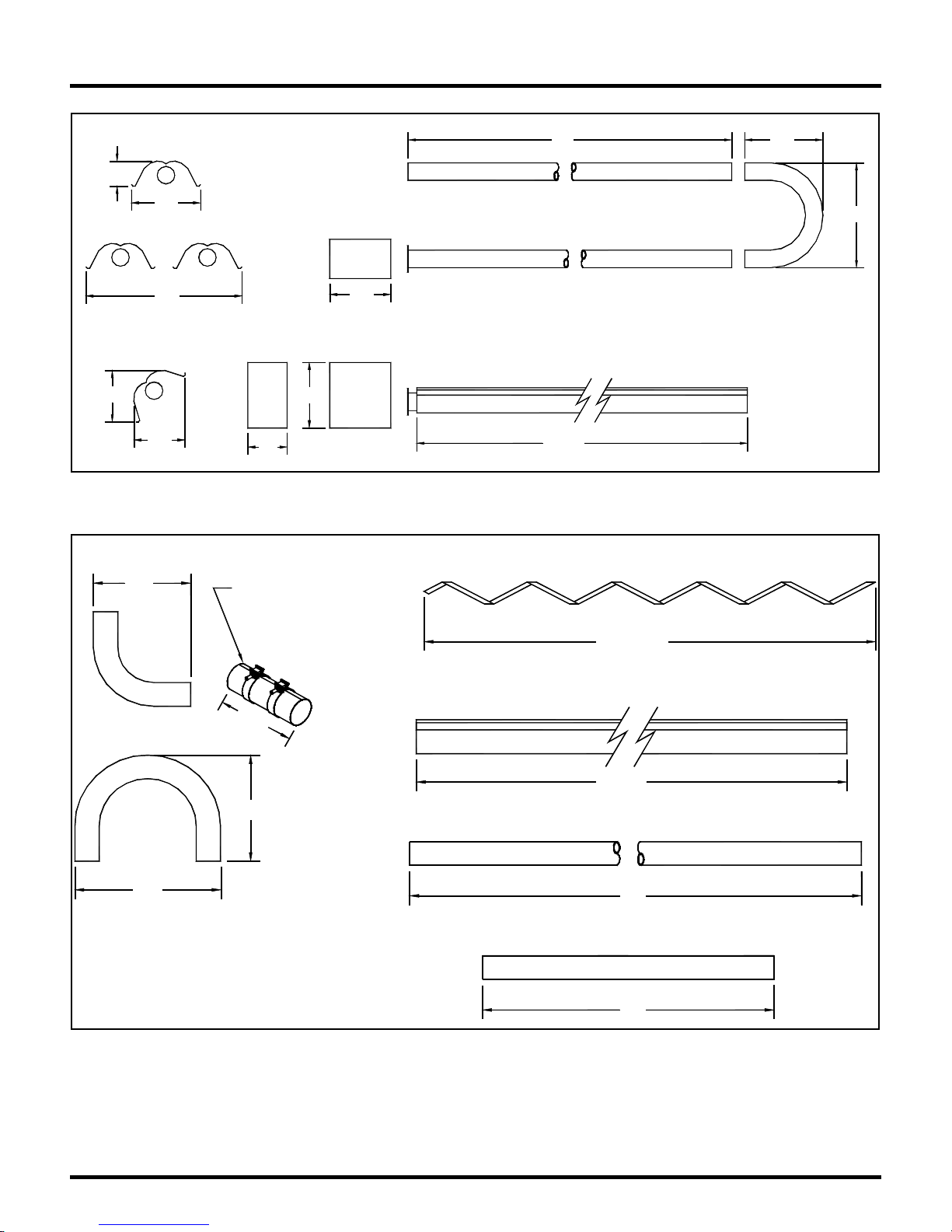
Dimensional Charts
6"
12"
ELBOW
16"
12"
16"
44"
14"
15"
9"
Figu re 1: Overall Dimensiona l Info rma tion
WHEN INSTALLING, ORIENT
BAND CLAMP LOCK BOLTS
TO TOP, AT 10 O'CLOCK
OR 2 O'CLOCK POSITION
10'
10' - 4"
18"
24"
BAFFLE SECTION
4' OR 6'
24"
U-BEND
12"
18"
COUPLING
REFLECTOR
10' - 4"
TUBE
10'
INSERT
4'
Figure 2: Component Dimensional Information
Series-LA/LX/LXR Page 4 6/15/2010
Page 7
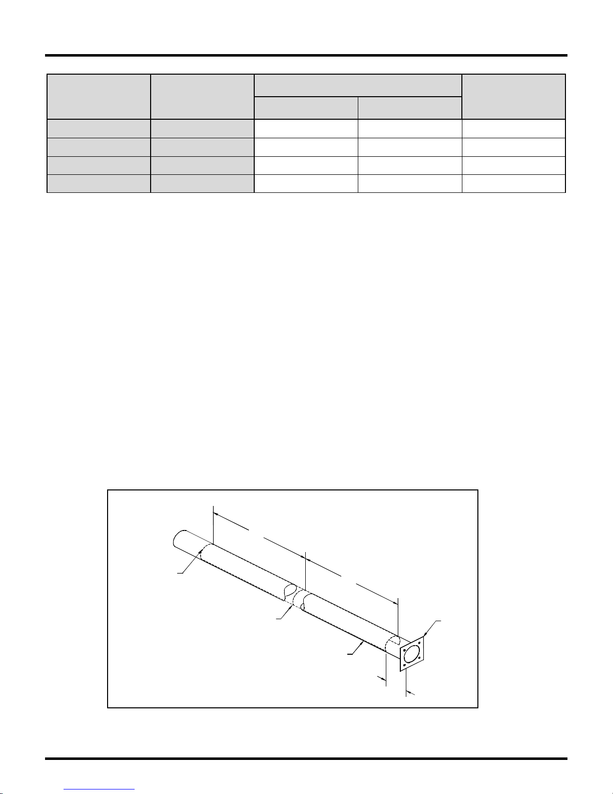
Configurations
Heat Exchanger Length (ft.)
Minimum Maximum
Baffle
Length (ft.)
Model
LA/LX/LXR-40
LA/LX/LXR-60
LA/LX/LXR-80
LA/LX/LXR-100
Rate
(BTU/Hr)
40,000 30' 40' 12'
60,000 30' 50' 12'
80,000 40' 60' 6'
100,000 50' 50' Three 4' lengths
Table1: Configuration Information
Note:
- Baffles are always placed in the last section of radiant tube except for the 100,000 BTU burner.
- Baffles are either aluminized or stainless stee l sectio ns 6' ft. long.
- When only 6' ft. is required (80,000 BTU), an aluminized steel baffle is installed (See Fig. 4)
- When 12' ft. is required (40,000 or 60,000 BTU) the aluminized steel baffle is lengthened
forward (toward the burner) with a 6' ft. stainless steel section that is twist locked to the first
section of Baffle. See Figure 5 for installation details.
- In the case of a 100,000 BTU system, place 4' sections of baffle in the end of each of the last 3
10' sections of tube. See Figure 6 for installation details.
Part numbers for reference are:
CT007 Baffle 6' ft. long, aluminized steel
CT006 Baffle extension, 6' ft. long stainless steel.
CT026 Baffle 4’ ft. long, aluminized steel.
Insert (Must Be Installed)
To further improve heat distribut ion along the length of the heater, two stainless steel inserts must be
installe d be low. The inser ts w ill re duce heat output in the first tu be, w h ich r e s ults in more heat relea s e in
the latter part of the heat exchanger.
Series-LA/LX/LXR Page 5 6/15/2010
(2) I n serts
P/N UT003
Inst a ll T wo 4 ' In s e rt s Into Comb ustio n Tu be
As I llustra t e d. T he T w o In s erts S hou ld B e
Butted Next To Each O ther. The Insert Closest
To The Burner Flange Should Be 3" in From
The End (As shown).
Figure 3: Stainless Steel Insert Installation
4'
4'
Tube
Flange
Combustion
Tube
3"
Page 8

Clearance To Combustibles
It is important to observe minimum clearance to combustibles at all times to avoid any possibility of
property da ma ge or perso nal injury. C lea rances must be maint aine d from veh icles parked bene ath
heaters. Signs should be posted identifying any possible violation of the clearance d istances from the
heater in vehicle areas. Also, maximum allowable stacking height in storage areas shou ld be identified
with signs or appropriate markings. Table 2 lists minimum clearance to combustible materials
corresponding to the installation configuration.
Approved reflector configurations include the standard (with or without decorative grille), the 45° tilt
reflector, single and dual side extension shields, standard U tube mounting and opposite 45° U tube
reflector mounting.
Bottom shields are also approved. The “below” clearance dimension for the horizontal configuration
(dimension “C” in Table 2) may be reduced by 25% when an approved bottom shield is used.
Reduced clearances downstr eam from the burner are approved for a ll configurations, except those with
the U-bend. Dimensions “B”, “C”, and “D” can be reduced by 50% for locations 25' feet or more
downstream from the burner box.
Elbows and U-bends are un-heat-treated aluminized mat erial and are t ypically installed without
reflectors. Clearance to combust ibles is 18" inches abo ve and from the end in all cases. When elbows
or U-bends must be reflectored due to the proximity of combustible material, a 90 degree mitered
reflector kit is available from your SRP dealer (part # CR039). Clearances in the case where mitered
reflector kits are used are the same as the previous section of reflecto r.
Series-LA/LX/LXR Page 6 6/15/2010
Page 9
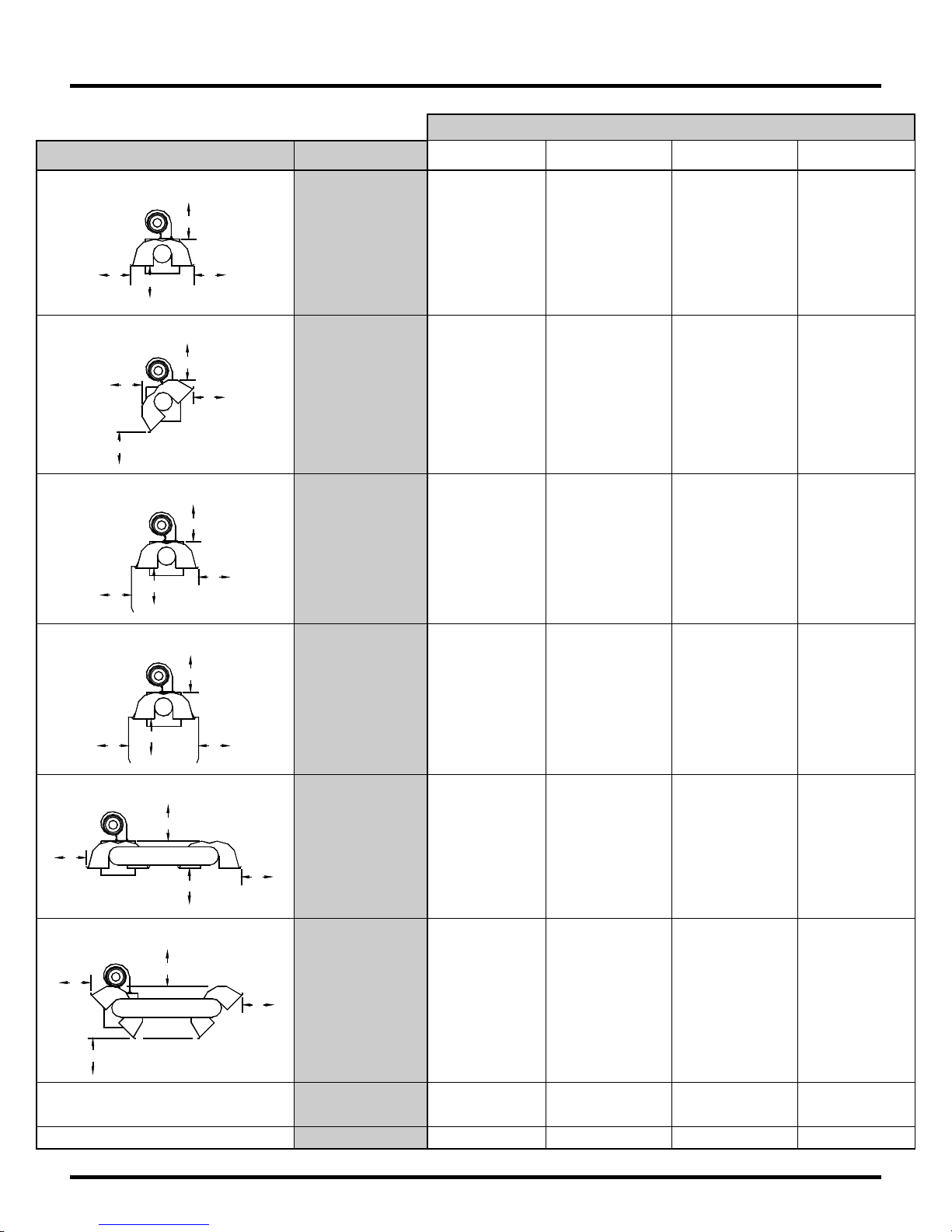
Clearance To Combustibles
Model No.: LA / LX / LXR
Refl ect or Configuratio ns Dimension
Horizontal
A
C
DB
45° Reflector Tilt
A
B
C
D
One Side Extension
A
C
B
D
Two Side Extension
A
A
B
C
D
A
B
C
D
A
B
C
D
A
B
40 60 80 100
2"
4"
31"
4"
3"
3"
18"
18"
2"
2"
35"
6"
2"
2"
2"
4"
31"
4"
3"
3"
18"
18"
2"
2"
35"
6"
2"
2"
2"
4"
31"
4"
3"
3"
18"
18"
2"
2"
35"
6"
2"
2"
2"
6"
36"
6"
4"
3"
20"
20"
2"
3"
36"
6"
2"
3"
C
B
U-Tube, Horizontal
A
B
C
U-Tube, Opposite 45°
B
C
A
Un-Vented Above
Vented End 18" 18" 18" 18"
C
D
D
A
B
D
C
D
A
B
D
C
D
End
38"
2"
2"
4"
32"
4"
3"
18"
18"
18"
12"
26"
38"
2"
2"
4"
32"
4"
3"
18"
18"
18"
12"
26"
38"
2"
2"
4"
32"
4"
3"
18"
18"
18"
18"
26"
38"
3"
2"
6"
38"
6"
4"
20"
20"
20"
18"
26"
Table 2: Minimum Clearance to Combustibles
Series-LA/LX/LXR Page 7 6/15/2010
Page 10
Installation Detail
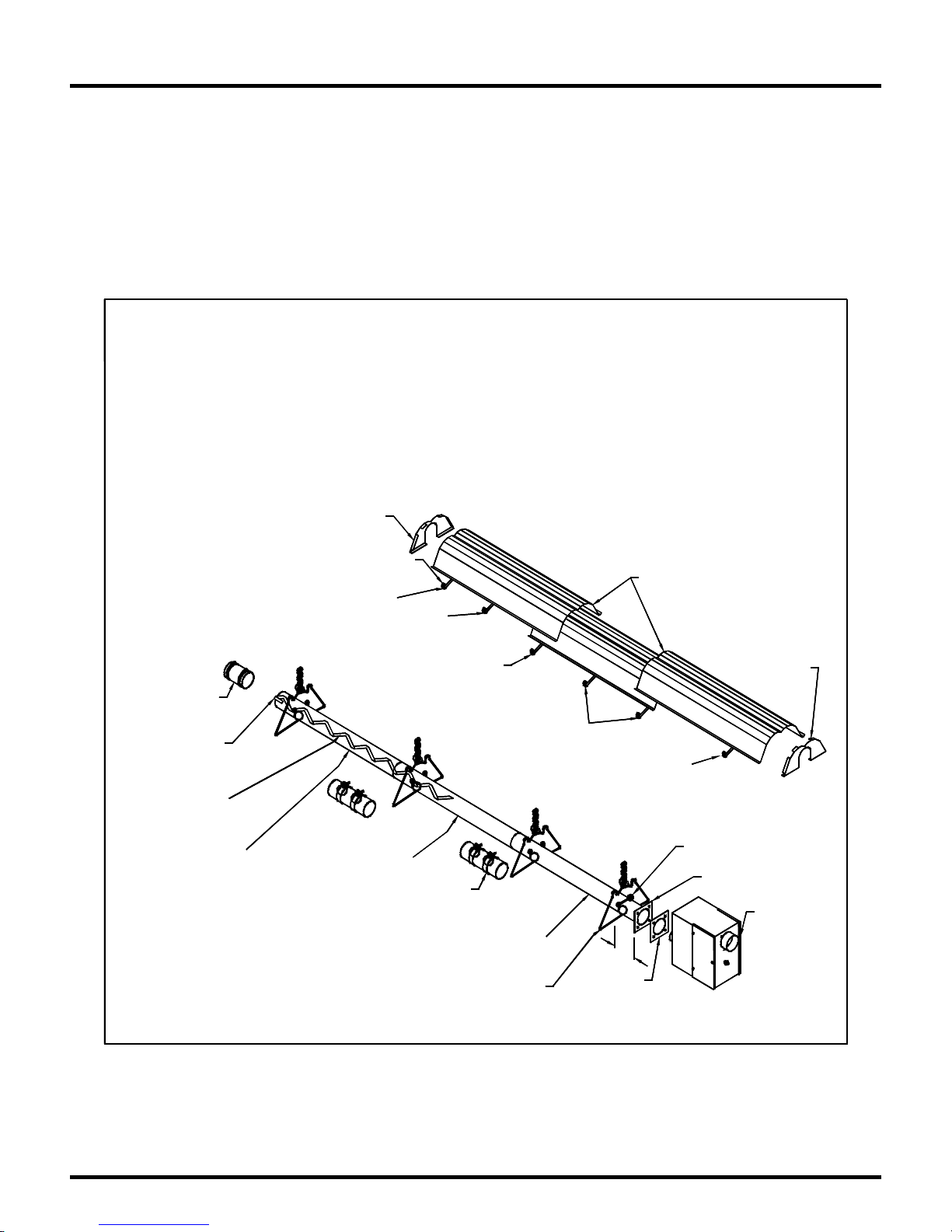
Generally, there is no unique sequence for installation of the burner or heat exchanger. A review of the
job site will usually indicate a logical installat ion order. However, time and expense can be saved if
installation is begun at the most critical dimension, watching for interference from overhead door s,
cranes, aut o lift s e tc. Figure 4-6 provides a gener al overview of the components utilized in the
installa tion, as w ell a s their gene ral relations h ip.
Install 12' Baffle
(2 - 6' Sections Twist
Lock Together)
(Grey Co lor) Tube
Vent
Adapter
Bend Tab
over End
of Tube
Heat Treated
Reflector
End Cap
Reflector
Support
Loose
Screws
Non Heat Treated
(Silver Color)
Tube
Loose
Screws
LA / LX / LXR 40,000 BTU
LA / LX / LXR 60,000 BTU
30' Long
For 40' and 50' Heaters follow the same sequence. The 12' baffle is
Installed in the last sections of tube.
Reflector Overlap
Approx. 8"
Tight
Screws
Loose
Screws
Tight
Screws
Install "J" Bolt
at first hanger
Tube
Couplin g
Combustion
Non Heat Treated
(Silver Color)
Tube
Tube & Reflector
Hangers
3"
Gasket
Fasten Endcap
with Screws
Tube
Flange
Burner
Assembly
Figure 4 Installation Configurations for 40,000 & 60,000 BTUH Model
Series-LA/LX/LXR Page 8 6/15/2010
Page 11
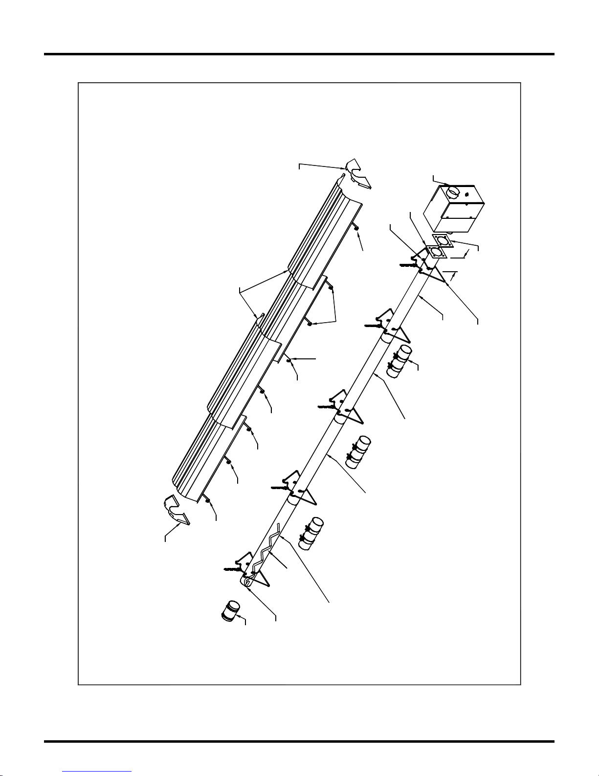
Installation Detail
with Screws
Fasten Endcap
Tube
at first hanger
Install "J" Bolt
Approx. 8"
Reflector Overlap
Tight
Screws
40' Long
For 50' Heater follo w the same s eq uence. The baffle is
LA/LX/LXR 80,000 BTU
Installed in the last sections of tube.
Loose
Screws
Reflector
Support
Tight
Screws
Loose
Screws
Loose
Screws
Non Heat Treated
Loose
Screws
End Cap
Reflector
Tight
Screws
Heat Treated
(Grey Color) Tube
Install 6' Baffle
Vent
Adapter
of Tube
over End
Bend Tab
Heat Treated
(Grey Color) Tube
Figure 5 Installation Configuration for 80,000 BTUH Model
Flange
Tube
(Silver Color)
Coupling
Tube
Assembly
Burner
3"
Gasket
Tube
Hangers
Combustion
(Silver Color)
Non Heat Treated
Tube & Reflector
Series-LA/LX/LXR Page 9 6/15/2010
Page 12
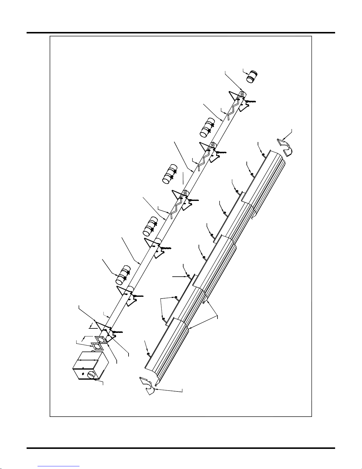
Installation Detail
Tube & Reflector
Hangers
Gasket
Coupling
(Silver Color)
Tube
3"
Burner
Assembly
Figure 6 Installation Configuration for 80,000 BTUH Model
Tube
Non Heat Treated
Bend Tab
Adapter
over End
of Tube
(Grey Color) Tube
Heat Treated
4' Baffle
(Grey Color) Tube
Heat Treated
4' Baffle
(Grey Color) Tube
Heat Treated
Screws
4' Baffle
Non Heat Treated
(Silver Color)
Tube
Screws
Tight
Reflector
Support
Combustion
Install "J" Bolt
at first hanger
Flange
Tube
Screws
Loose
Screws
Tight
Fasten End cap
with Screws
Screws
Screws
Loose
Loose
Loose
Reflector Overlap
Approx. 4 to 8"
Vent
Reflector
End Cap
Screws
Loose
Screws
Loose
Screws
Tight
LA/LX/LXR 100,000 BTU
50' Long
For 60' Heater follow the same sequence. The baffles are
Installed in the last three sections of tube.
Series-LA/LX/LXR Page 10 6/15/2010
Page 13
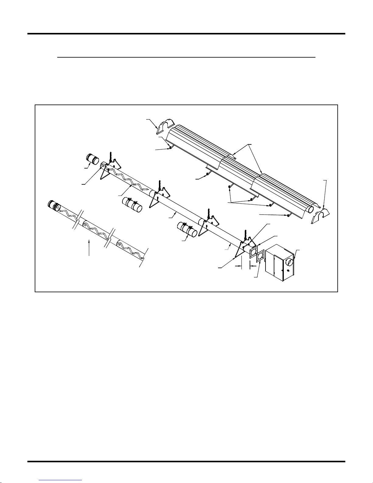
Installation Sequence
A general ordered sequence for installation is provided below for reference.
• Locate hanging chain at predetermined suspension points in the structure. It is re quired that the
• first hanging point be 2" inches to 8" inches from the burner mounting flange, the second
Reflector
End Ca p
Reflector
Vent
Adapter
Bend Ta b
over End
of Tube
In 100,000 BTU systems, place 4' baffles in
the last 3 ten fo ot tube lengths as sh own.
Instal l B affle
as required in
last section
of tube
Support
Loose
Screws
Exchanger
Heat
Tube
Coupling
Tight
Screws
Loose
Screws
Tube
Combustion
Tube
Tube & Reflector
Hangers
Reflector Overlap
Approx. 8"
Fasten Endcap
with Screws
Tight
Screws
Install "J" Bolt
at first hanger
Tube
Flange
Burner
Assembly
3"
Gasket
Figure 7: General Overview of Installation
• Hanging point should be about 8' feet to 9' feet away. Thereafter, 10' feet apart on average is
acceptable for the remainder of the heat exchanger. At no time should hangers be more than 12'
feet apart.
• Always use all the hangars supplied. As a rule the combustion tube ( first t ube) utilizes 2 hangers
and there after 1 hanger per 10' section.
Series-LA/LX/LXR Page 11 6/15/2010
Page 14
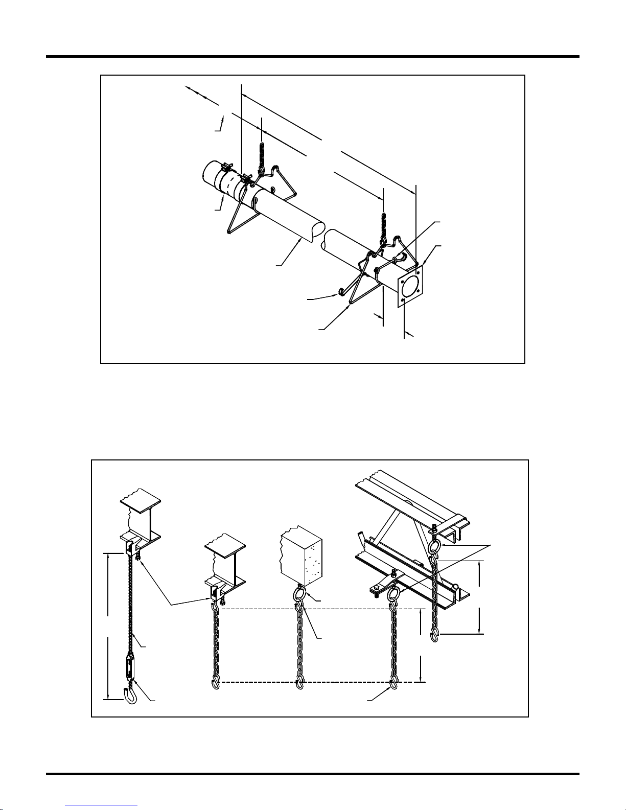
Installation Sequence
Locate Tube and
Reflector Ha ng ers
every 10' thereafter.
Coupling Should Be
Loosely Fitted
• S uspension me cha nism must allow fo r lateral tubing expansion. A minimu m 12" inch length
welded link chain with a working load limit of at least 200 lbs. is recommended. Close all open
ended S hooks and turnbuckles to avoid unhooking chain with inadvertent contact.
I-Beam
24"
Min.
Beam Clamp
3/8"
Threaded
Rod
Turnbuckle
10'
Combustion
I-Beam
Tube
Reflector
Support
Tube & Reflector
Hangers
Figure 8
Concrete Beam
Figure 9
10'
8' - 9'
Anchor
Note:
Close all "S" Hooks,
Turnbuckles, "J" Bolts.
"S" Hook
Install "J" Bolt
at first hanger
Tube
Flange
3"
Truss
Eye Bo lt
12"
Min.
12"
Min.
Series-LA/LX/LXR Page 12 6/15/2010
Page 15
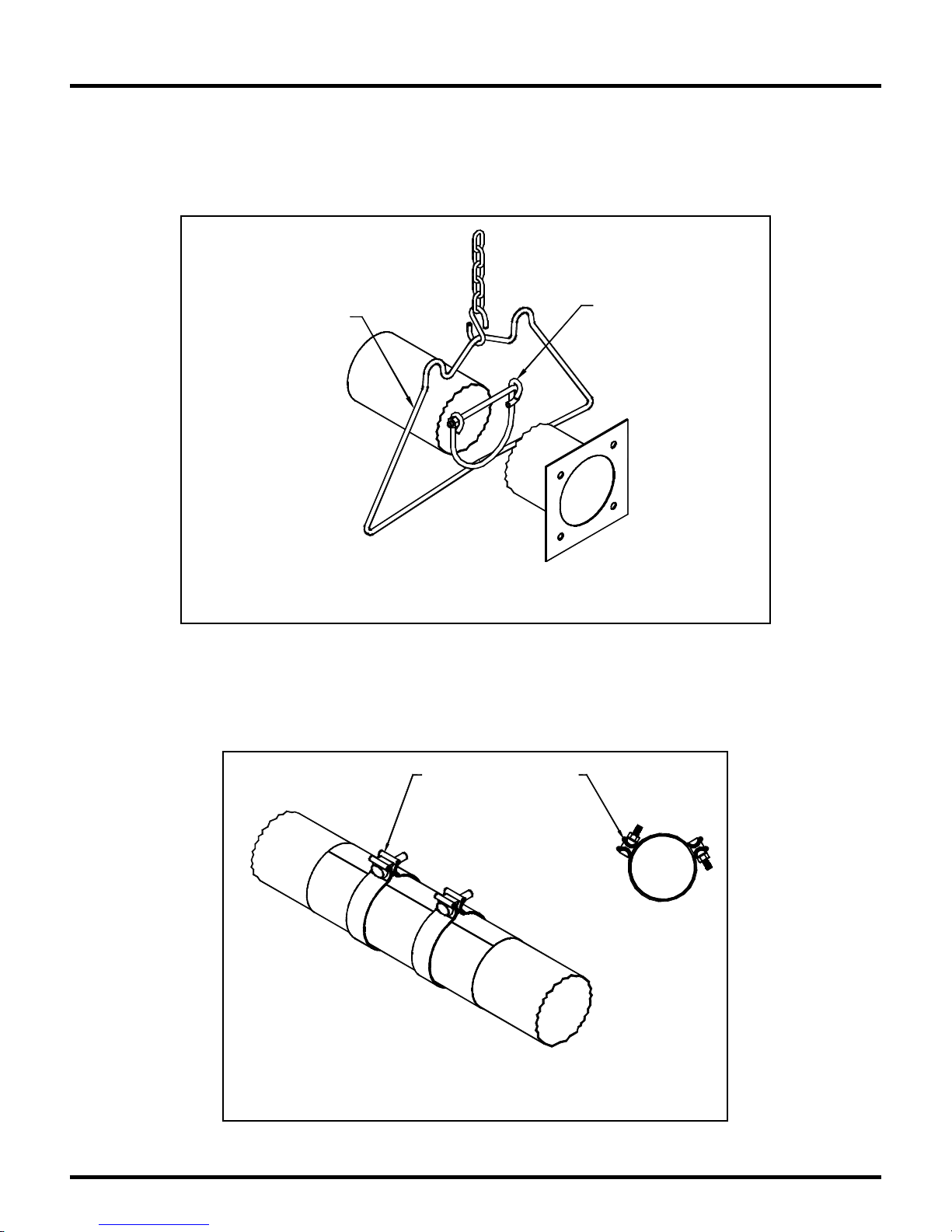
Installation Sequence
• Install the tube and reflector support hanger on the chain with “S-hooks”.
• P lace the first (f langed, aluminized) tube in the first two hangers. Be sure the flange is toward the
intended burner location. The other end of the tube should have the first coupling already loosely
fitted. Tighten the cradle loops of the first hanger with the “J-Bolt” found in the burner box to
snugly hold the combustion tube from rotating.
Reflector Hanger
Place T ube in the
Reflector Hanger
as shown.
Installation of Reflector H angers
and "J" Bolt
Figure 10
Note: For all coupling joints, ensure that the tube joint is in the center of the coupling length,
and that the overlap joint of the coupling is above the centerline of the tube. Also ensure that
the weld seam on ALL tubes is facing down.
When Insta lli ng, Orient
Band Clamp Lock Bolts
to Top, at 10 o' clock
Or 2 o'clock Position to
Avoid Contact with the
Reflector.
Installa tion of Tube Coupling
Figure 11
Install "J" Bolt at the
First Hang er Onl y .
Series-LA/LX/LXR Page 13 6/15/2010
Page 16
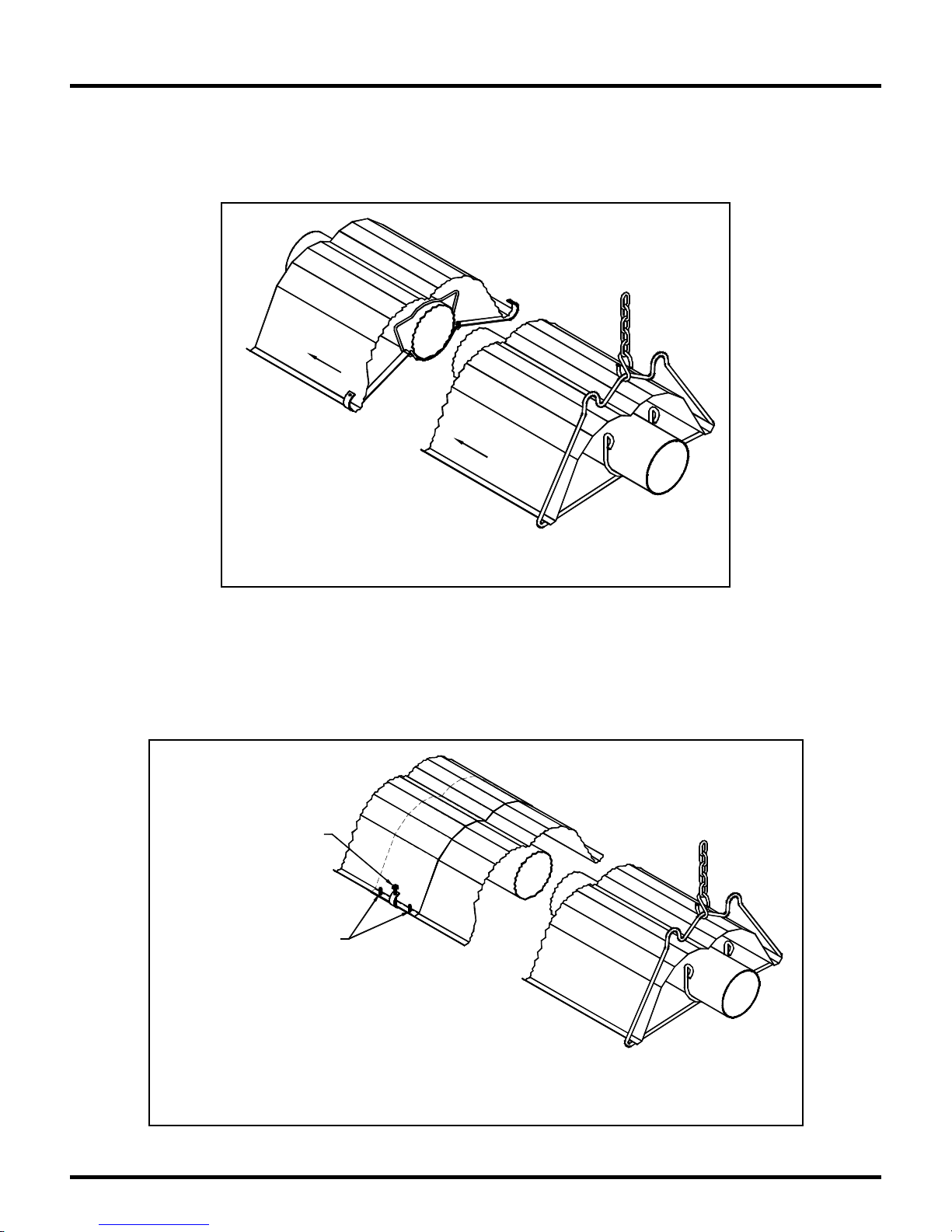
Installation Sequence
• Locate the burner gasket provided, bolt the burner in place on the tube flange with provided
hardware. Burner must never be installed in a tilted position. The sense electrode of the burner
cup should be in the 12 o’clock position.
• S lide a reflecto r section into place w ithin the support hanger.
• Co nt inue placing tubes, co uplings and reflectors to complete the heater assembly. Ensure heat
exchanger sections line up straight. Couplings should be tightened as heat exchanger is placed,
since it is more difficult to do so once the reflector is in position. Reflecto r s should over lap
adjacent reflectors 4" to 6" inches.
Secure reflector to reflector
bracket by tightening
#8 x 1 1/4" long screws every
other over lap on each side.
Secure every second reflector
overlap with a minimum of 2
Slide Reflector through
the Hanger and Reflector
Support as shown.
Installation of Reflector Sections
Figure 12
#8 x 3/8" long screws
on each side
Installation of Reflector Supports
and Reflector Overlaps
Figure 13
Series-LA/LX/LXR Page 14 6/15/2010
Page 17
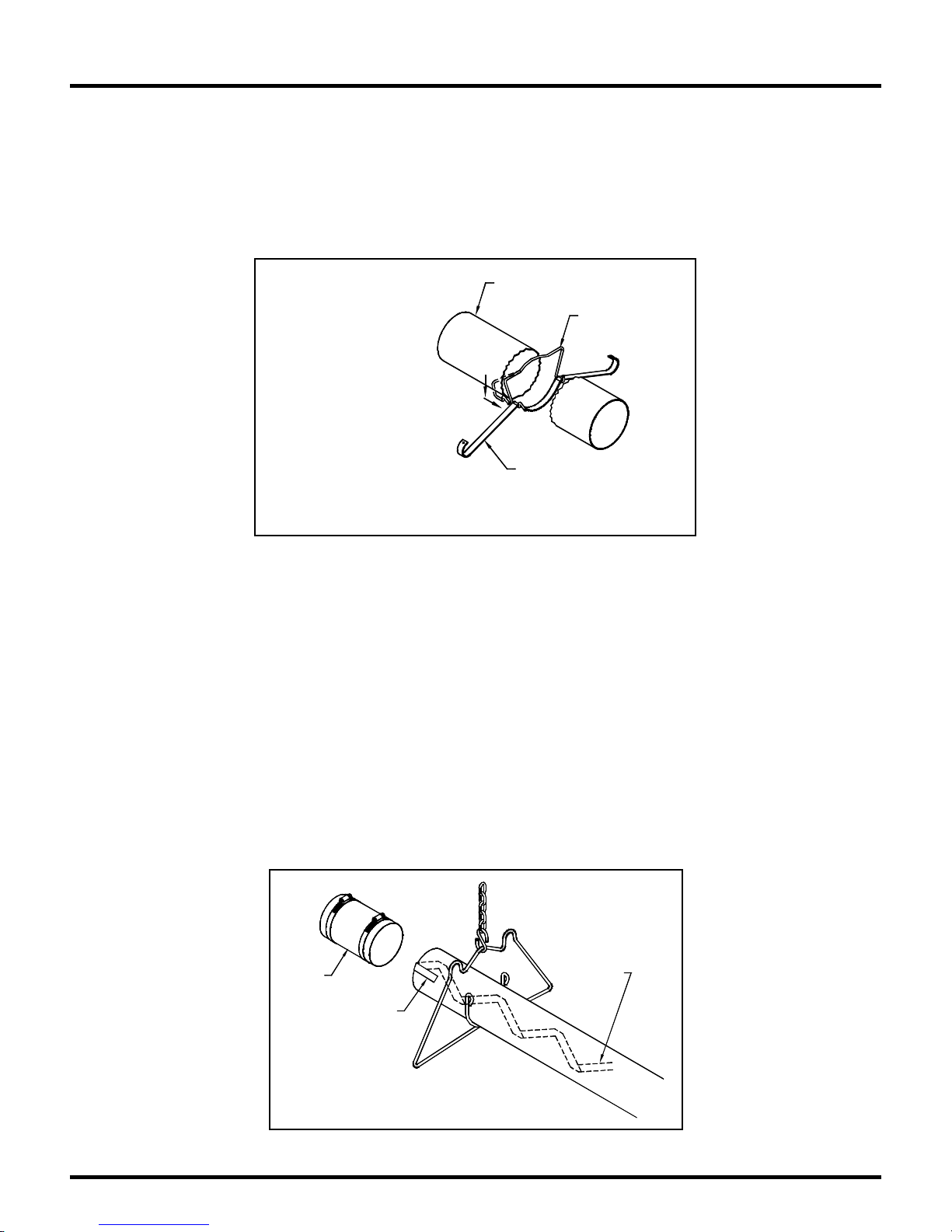
Installation Sequence
Note: In order to obtain smoothly sealed coupling liners, tighten each of the coupling bands
progressively and alternately. Tightening one band completely before the other may result in
an undesirable wrinkle in the liner.
Note: Be sure not to tile reflector sections; that is, reflector sections must be either above both
adjacent reflector sections, or below both adjacent reflector sections.
• Insta ll reflector support brackets, one at each reflector overlap position, and one in the middle of
each 10' foot reflector length.
1. Place Reflector Bracket
underneath the tube.
2. Hook the Spri ng Clip wi th
the Reflector Bracket and over
the tube.
3. Push down the Spring Clip
and slide underneath the
Reflector Bracket.
Installation of Reflector Support Brackets
Figure 14
• Secure ever y second re flector overlap together with a minimum of 2 - #8 x 3/8" inch long screws
(not supplied), and secure reflector to the reflector bracket at this point by tightening down #8 x
1¼" inch screws supplied with reflector bracket s. The remaining reflecto r overlap joints and
reflector bracket s ar e left loose to accommodate s ystem movement .
• If required for your heater model (refer to Table 1), install the baffle at the end of the heat
exchanger. The small tab on the baffle is folded over the end of the tube and clamped in place by
the vent connector and vent syste m.
Note: Baffles are always placed at the end of the last heat exchanger tube length, with the
exception of the 100,000 BTU units which gets a 4’ section in the last three 10’ sections.
Note: Baffles are either one or two sections (4’or 6’). 6’ sections are simply twist locked
together. Where stainless and aluminized sections are supplied, always place the stainless
steel section closest to the burner. The easiest installation method is to pull the baffle through
the tube using a long wire.
Vent
Adapter
Bend Tab
over End
of Tube
Baffle Installation
Figure 15
Tube
Spring Clip
Reflector Bracket
Reflector Bracket
Install Baffle
as required in
last secti on
of tube
Series-LA/LX/LXR Page 15 6/15/2010
Page 18
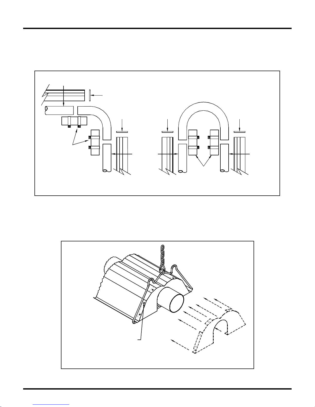
Installation Sequence
• If required by the heater layout, install 90° elbows or U-tube where indicated. Refer to Figure 16
for d eta ils .
Note: Elbows or U-bends are typically installed without reflectors. To reduce the above
clearance to combustibles distance use mitered reflectors (see figure 15) and refer to
Clearance to Combustibles information.
Hanger
Location
Endcap
Couplings
Elbow Detail
Endcap Endcap
Hanger
Location
Couplings
U-Bend Detail
Endcap
Hanger
Location
Figure 16: 90° Elbow and U-Tube Assembly Detail
• Elbows or U Tubes must be located not less than 20' feet from the burner in LA/LX/LXR-100 and
sma ller mo de ls .
• Insta ll End Cap as shown in Figure 17 and the figure below.
Insert End Cap into Reflector
and Secure i t wi th #8 x 3/8" Screws
Installation of End Cap
Figure 17
Series-LA/LX/LXR Page 16 6/15/2010
Page 19
Installation Sequence
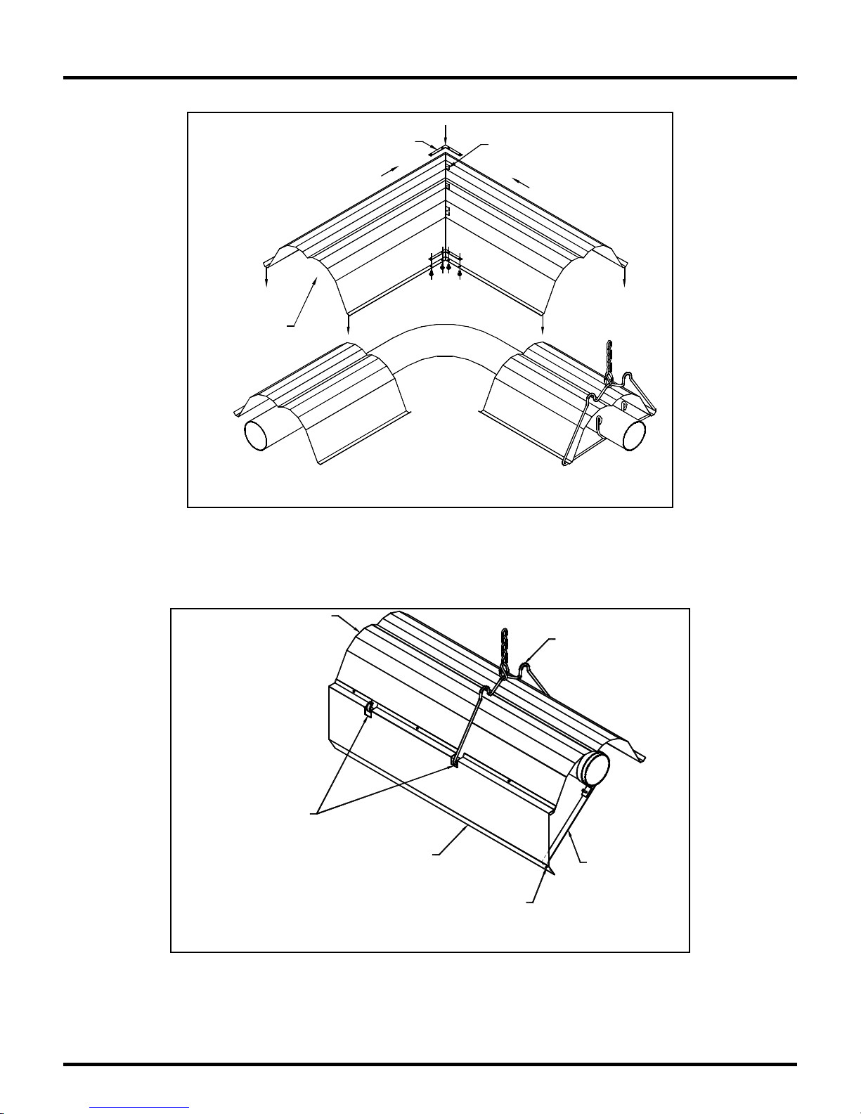
• If used, insta ll the Mitered reflecto r as shown below.
Mitered Reflector
Sections should
overlap standard
Reflectors.
• If used, install side shields (reflectors) and/or bottom shield as required. Refer to Figures 19-21 for
details.
for Reflector Bracket
and Tube & Reflector Hanger
• S ide shields are 124" inches long. Fasten one side shield per reflector with #8 x 3/8" inch screws.
Use three side shield brackets per side shield. Spac e abou t 48" inches apart.
Assemble Corner Bracket
to Mitered Refle c to rs as shown
Installation of Mitered Reflector Sections
Reflector
Relief Notch
Installation of Side Reflector
(Side Shields)
Figure 18
Side Reflector
Figure 19
Fasten Mitered Reflectors
with 4 #8 x 3/8" S c rews
Tube and Reflector Hanger
Side Shield Support
#8-3/8 Screw
Series-LA/LX/LXR Page 17 6/15/2010
Page 20
Installation Sequence
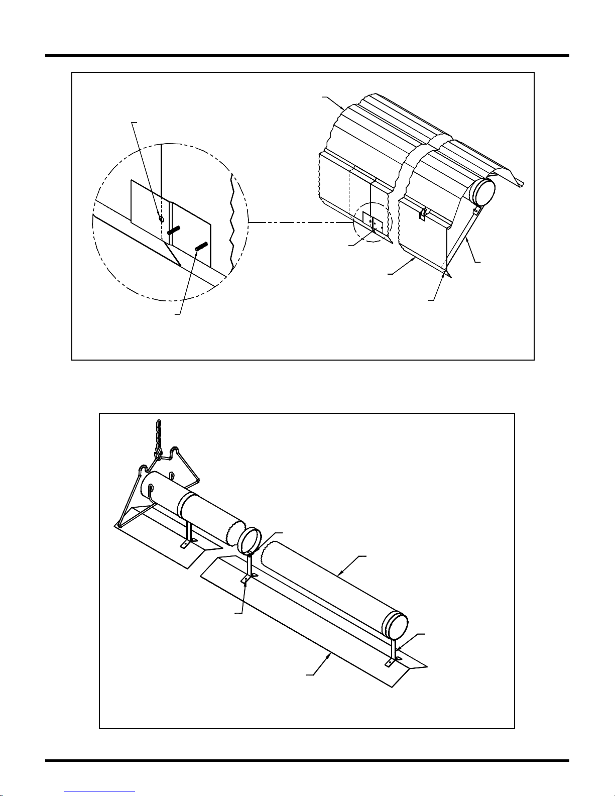
Use hole as a guide to
position side reflector.
The side reflector end must
be visible through the hole
at room temperature.
Screws to be installed
from inside of s ide
reflector. Install screws
on one end of the bracket
to allow movement.
Installation of Side Reflector Overlaps
• Bottom shields need not overlap. Each 5' feet section is held with two support bracket s.
#8 x 3/8" screws
Bottom Shield
Installation of Bottom Shields
Reflector
Side Reflector
Retainer Bracket
Figure 21
Tighten Screw
Figure 22
Side Reflector
Side Shield
#8 X 3/8" Screw
Tubing Section
Support Bracket
Side Sh ie ld
Support
Series-LA/LX/LXR Page 18 6/15/2010
Page 21
Installation Sequence
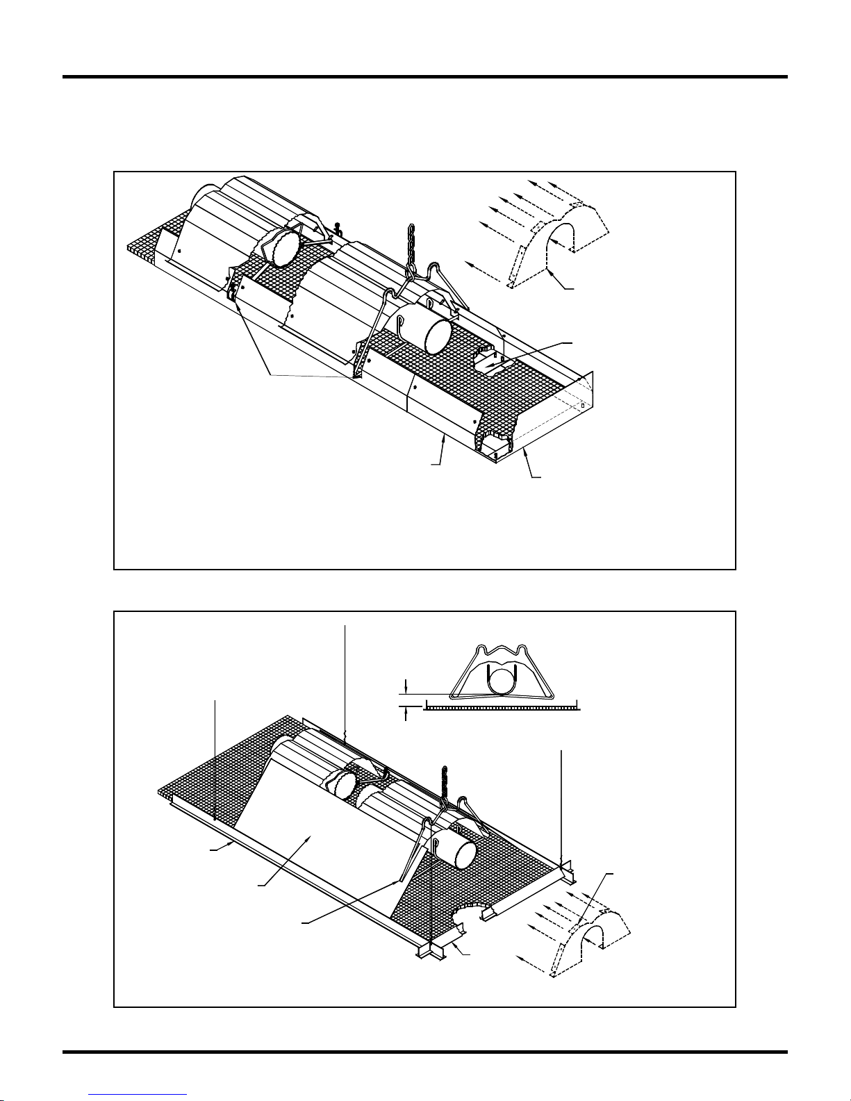
Deco-Grille Opti on
Series LA/LX/LXR heat er s are approved for the addition of Deco-Grille either directly to the heater
reflector or as part of a T-Bar installation where t he heater is above the ceil ing str u ctur e. Refer to figures
23 and 24 below for details.
Notch Deco-Grille Support
for Hangers an d Supports
Deco-Grille Support
Installed from inside of Shield
and held by Scre ws fr om outside
Installation of Deco-Grille Mounted Directly to Heater
Install End Cap as per
"Install at ion of End Cap"
Figure
Deco-Grille Cross Strap
Fastened with Screws
Deco-Gri lle End Angle
Fastened to Deco-Grille Supports
and Trim edges as required
Figure 23
2" Min.
T-Bar Susp ended
Ceiling
Reflector Shield
(Cut to fit Deco-Grille)
Notch Reflector Shield
as re quired for Hanger s
and Reflector Supports
Install End Cap as per
"Installation of End Cap"
Figure
T-Bar
Shield
Installation of Deco-Grille on Suspended Ceiling
Series-LA/LX/LXR Page 19 6/15/2010
Figure 24
Page 22

Venting / Combustion Air Ducting
General Require ments
• Re fer to the National Fuel Gas Code, ANSI Z223.1 (NFPA 54) in the US and CAN/CGA B149.1
and B149.2 Installation Codes in Canada , as wel l a s all loca l r e quire ment s for gener al venting
guidance.
• Ser ies LA/LX/LXR Infrared Heaters may be installed vented or unvented.
• Series LA/LX/LXR Infrared Heaters may be vented horizontally or vertically using conventional
venting mat e r ials .
• I f he ater is to be vented hor izontally, t he vent from building must :
o Be not less than seven feet above grade when located ad jacent to public walkways.
o Terminate at least three feet abo ve any forced a ir inlet locat ed within t en feet.
o Terminate at least four feet below, four feet hor izonta lly from or one foot abo ve any door,
wind o w, or gr a vity inlet into any bu ild in g.
o Be located at least 12" inches from any opening through which vent gases could enter a
building.
o Be be yond any c ombustible overha ng.
o Be installed at a height sufficient to prevent blockage by snow.
• Opt ional out s ide air supply may be directed to t he heater horizonta lly or vert ically.
Important
Max imum total vent length allo wed for a ny model he ate r is 30'
feet.
Maximum total fresh air inlet duct length allowed for any
mo del he ate r is 30' feet.
Total of vent length plus outside air supply duct length cannot
exceed 50' feet for any heater with maximum heat exchanger
length.
If condensation outside the vent pipe duct is a problem, then
make provisions for removal or containment.
Note: The above stated requirements assume a maximum of 2
elbows in the total combination of vent and air supply duct.
Subtract 5' feet of allowable length for each elbow if 3 or more
elbows are used. Do not use flexible duct for fresh air supp ly
duct.
Un-Vente d Operation
• In genera l, where heaters ar e installed without direct outside combustion air, fresh air vent ilation
must be provided to the building space (4 cfm per 1000 BTU/Hr in USA, 3 cfm per 1000 BTU/Hr
in Canada). Verify applicable codes.
• Opt ional outs ide air supply is not recommended for unvented heaters due to poss ible pressure
imbalances in the building space.
• Ensure t hat minimum co mbust ible clearances are ma inta ined for unvent ed heat er s. Refer to Table
2, for required clearance dimensions.
Series-LA/LX/LXR Page 20 6/15/2010
Page 23
Venting / Combustion Air Ducting
Vented Operation
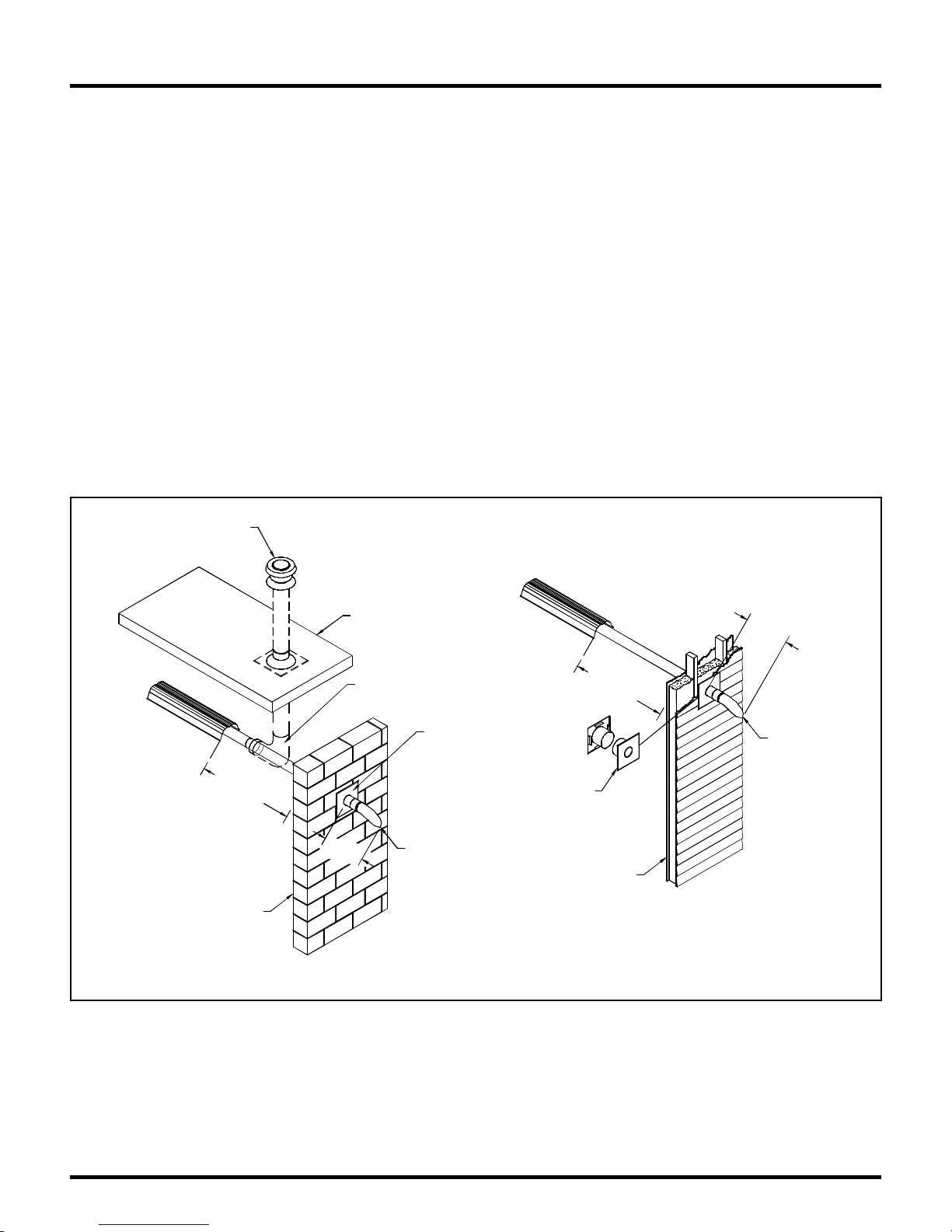
In all cases, be sure vent pipes and outside air supply ducts are sealed with approved sealant, such as
high temperature RTV silicone. Double wall venting (B vent) may not require sealant.
Horizo ntal Ve nting
• When vent ing through combustible walls, use approved vent terminal Tjernlund VH1-4, or SRP
supplied deflecto r terminal w ith an app roved ins ula ting thimble.
• When vent ing through non-combustible walls, use SRP supplied deflector vent terminal.
Recommended extension of t he terminal past t he outside wall s urface is 18" inches minimum.
Vertical Venting
• Minimum vent pipe size is 4" inch for an individual heater. Additional vent pipe sizes as required
to accommodate multiple heater s venting through a common roof vent are defined in the
appropriate gas installation code. (Refer to common venting section below).
• Us e of an a pproved thimb le to pass through c ombu s tible roof materia ls is re quired.
• Use of an approved vent cap is required.
• Check local codes for vertical vent size for fan-assisted appliances.
FOR VERTICAL VENTING REFER TO
ANSI Z223.1 AND CA N /CGA B149.1
AND B149.2 FOR FAN ASSISTED
APPLIANCES.
MAX. 30'
WITH 2 ELBOWS
NON-COMBUSTIBLE WALL
ROOF
INCREASE TO DETERMINED
"B" VENT SIZE
18" MIN.
4" VENT
TERMINAL
P/N CT011
NOTES: (FOR HORIZONTAL VENTING)
1- USE 4" SINGLE WALL VENT FOR HORIZONTAL VENTING
2 - WALL THIMBLES AND VENT TERMINALS
MUST TO BE USED WITH SINGLE WALL HORIZONTAL VENTING THROUGH COMBUSTIBLE WALLS.
WALL THIMBLE MAY BE REPLAC ED BY FLA SH ING WHERE THE VENT IS PENETRATING
A NON-COMBUSTIBLE WALL.
FLASHING
WITH 2 ELBOWS
4" WALL THIMBLE
P/N CS006
COMBUSTIBLE WALL
MAX. 30'
18" MIN.
4" VENT TERMINAL
P/N CT011
Figure 25
Series-LA/LX/LXR Page 21 6/15/2010
Page 24
Venting / Combustion Air Ducting
Common Roof Venting
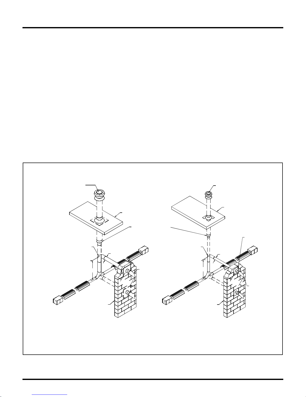
• A maximum of 4 heaters can be vented through a common vertical stack. Common vent sizing
information is defined in the appropriate gas installation code (Refer to ANSI Z223.1 and
CAN/CGA B149.1 and B149.2 for sizes and installation information). Copies can be obtained
from your local SRP representative or directly from Superior Radiant Products.
• Us e of a n approve d thimble to p a s s through c ombu s tible roof materials is required. Ad ditionally,
B type vent materials are required for stacks above the roo f line.
• Use of an approved vent cap is required.
• The o pen area of the common vent must equal the sum of the open areas of each of the flue pipes
connected to the common vent.
• Co nnect ion locations to the common vent should be offset to avoid pressure interferences between
heaters.
• All heaters connected to a common vent must operat e at the same time. Co nnect t he electrical
circuit to the same thermostat to ensure simultaneous operation.
Common Horizontal Venting
WITH A COMBINED TOTAL I NPU T OF 250 ,000 BTUH OR GREATER
FOR VERTICAL VENTING REFER TO
ANSI Z223.1 AND CAN/CGA B149.1
AND B149.2 FOR F AN ASSISTED
TOTAL VENT LENGTH FOR SINGLE WALL VENTING
(INCLUDING ELBOWS) = 40'
MAX. NUMBER OF ELBOW = 3
COMMON VENTING FOR HEATERS
APPLIANCES.
EACH ELBOW = 5'
5' MAX .
WALL
COMMON VENTING FOR HEATERS
WITH A MAX. TOTAL INPUT OF 250,000 BTUH
FOR VERTICAL VENTING REFER TO
ANSI Z223.1 AND CAN/CGA B149.1
AND B149.2 FOR F AN ASSISTED
ROOF
ROOF
INCREASE TO DETERMINED
"B" VENT SIZE
TOTAL VENT LENGTH FOR
SINGLE WALL VENTING
(INCLUDING ELBOWS) = 40'
6"
6" VENT
TERMINAL
P/N CT044
18" MIN.
MAX. NUMBER O F ELBOW = 3
EACH ELBOW = 5'
4"
5' MAX.
18" MIN.
WALL
APPLIANCES.
FOR COMBUSTIBLE WALLS
4" WALL THIMBLE
P/N CS006
6" WALL THIMBLE
P/N CS033
4" VENT
TERMINAL
P/N CT011
Series-LA/LX/LXR Page 22 6/15/2010
NOTES: (FOR HORIZONTAL VENTING)
1- USE 4" SINGLE WALL VENT WITH HEATERS OF COMBINED INPUT OF UP TO 250,000 BTUH
AND 6" FOR A COMBINED TOTAL INPUT OF 250,000 BTUH OR GREATER.
2 - WALL THIMBLES AND VENT TERMINALS
MUST TO BE USED WITH SINGLE WALL HORIZONTAL VENTING THROUGH COMBUSTIBLE WALLS.
WALL THIMBLE MAY BE REPLACED BY FLASHING WHERE THE VENT IS PENETRATING
A NON-COMBUSTIBLE WALL.
Figure 26
Page 25
Combustion Air Supply
Combusti o n Ai r Supply (Optional)
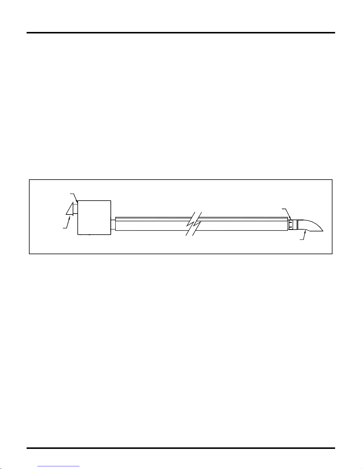
• An outs ide co mbustion air supply is strongly recomme nded if the building space encloses a
negati ve pre ssure due to exhaust et c. or if the bui lding contains material s which wou ld expose the
heater to halogenated hydrocarbon atmospheres.
• The out side air terminal must be o f an approved type, and should be located at an elevation equal
to o r below t he vent terminal elevation to pre vent back-ve nting of flue gas e s int o the burne r
compartment.
• Flexib le duct is not recommended for the ent ire run of the fresh air supply nor is it recommended
to form elbow or U bends. A short piece of flexible duct is recommended to connect the fresh air
supply to the heater to allow for some thermal expansion of the heater, this short piece should be in
a linear position and should not have a length longer than 24 inches.
Outdoor Installation (LXR Models Only)
When a heater is to be mounted outdoors it must be installed in such a way that wind will have
minimum effect on its movement. This considerat io n is intended to eliminate undue stress o n the gas
flex connector. In all cases a fresh air hood must be used in conjunction with a vent terminal of the
Seal Joints
Seal Joints
Seal Joints
Seal Joints
Fresh Air
Fresh Air
Inlet Hood
Inlet Hood
Vent Terminal
Vent Terminal
Outdoor Installation
Outdoor Installation
Figure 27
approved type, and all connections must be sealed with a high temperatur e sealant that can withstand
400°F.
Note that this heater is a sealed construction. If any services o r repair is conducted in the futur e, gasket
materials should be inspected and replaced if found to be deteriorated.
Series-LA/LX/LXR Page 23 6/15/2010
Page 26
Gas Piping
General Require ments
• The gas meter and service must be sufficiently large to supply gas to the connected building gas
load including the heating equipment and any other gas fired equipment. Additionally, the gas
distribution piping must be designed according to local and national ordinances. Generally (low
pressure) systems designed with a maximum ½" inch w.c. total pressure drop meet this
requirement.
• Gas supply pipe sizing must be in accordance with the National Fuel Gas Code, ANSI Z223.1
(NFPA 54) in the US and CAN/CGA B149.1 and B149.2 Installation Codes in Canada.
• Be fore connecting burners to the gas supply system, verify that high pressure testing of the system
has been completed. Failure to do so may e xpose the burner components to damaging high
pressure, requiring replacement of key components.
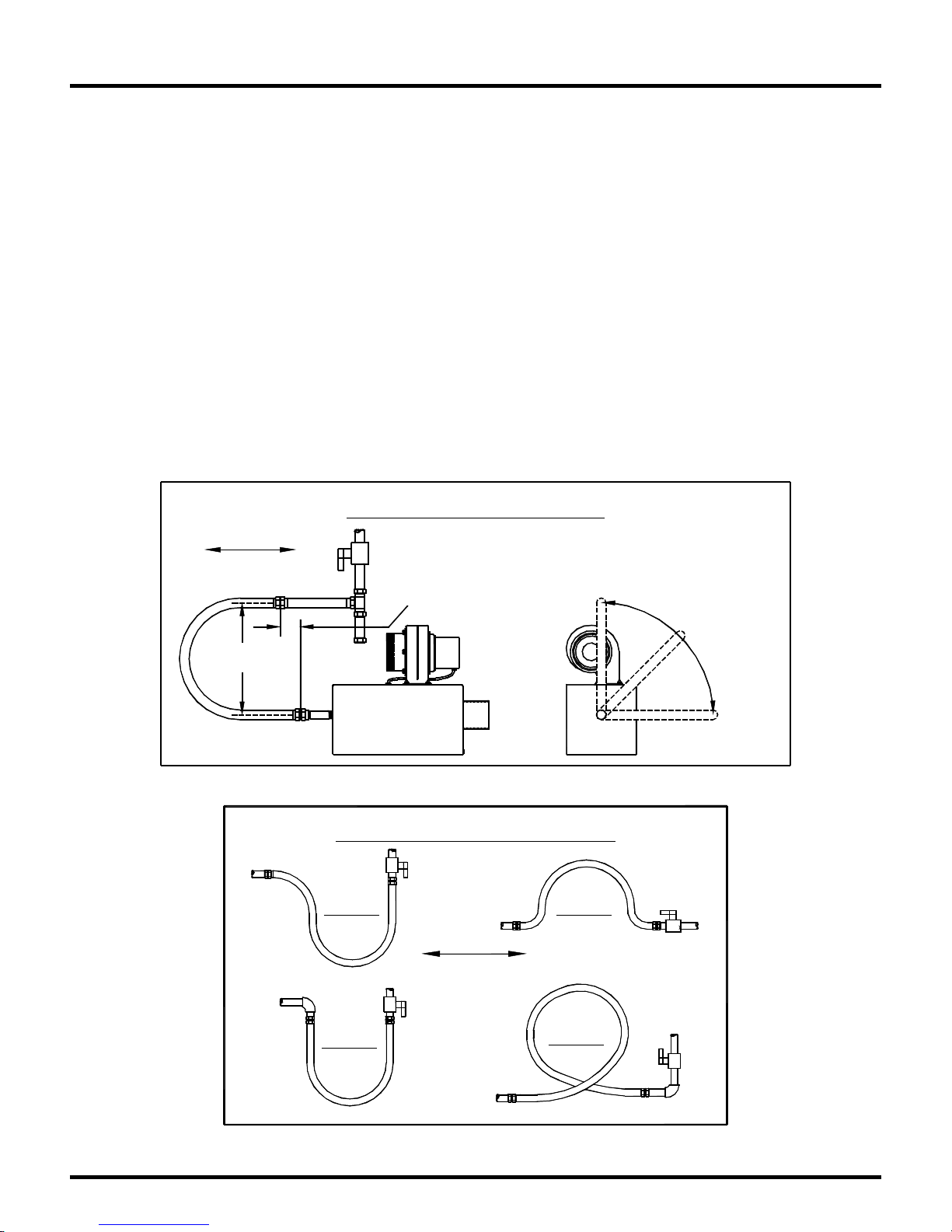
Flexible gas connectors of approved type must be installed as shown in Figur e 28A, in one plane, and
without sharp bends, kinks or twists. A smooth loop of approximately 12" inches in diameter is best.
Failure to install the gas connection in the approved manner will result in a hazardous and potentially
deadly situation due to the movement of the heat exchanger and burner in the nor mal course of
op e ration. The ga s s hut off valve must be insta lled p arallel to the burn e r gas inlet co nnectio n.
CORRECT POSITIONS
Heater Move me nt Vertical
12"
(30 cm)
3" (7.62 cm) Max.
Displacement
Figure 28A
(As Shown Below)
Alternate
Positions
Okay
INCORRECT POSITIONS
WRONG WRONG
Series-LA/LX/LXR Page 24 6/15/2010
WRONG
Heater Movement
WRONG
Figure 28B
Page 27
Electrical Wiring
General Require ments
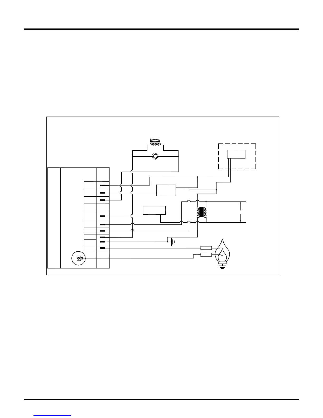
Heaters are normally controlled by line vo ltage or low voltage (24V) ther most ats. In all cases, heater s
must be grounded in accordance with the National Electric Code, ANSI/NFPA 70 in the US, and the
Canadian Electric Code, CSA C22.1 in Canada, and must comply with all local requirements. Heaters
may also be controlled with a manual l ine switch or timer sw itch in pla ce o f the thermostat . R e fer to
Figure 29 for guidance on electrical wiring of heaters.
If any of the original wire as supplied with the heater must be replaced, it must be replaced with wiring
having a rating of at least 105°C temperature service and 600 volts capability.
FENWAL DSI
CNE Controls DSI
TH
PSW
V1
IND
L1
24V
V2
GND
S1
HV
Wiring Diagram All Models LA/LX/LXR
GAS VALVE
Yellow Brown
Orange
Black
Yellow
Red
BLOWER
Green
Pink
RUN
LAMP
Brown
AIR
SWITCH
Black
Blue
Purple
Purple
Yellow
24V
Red
TRANSFORMER
SENSOR
IGNITER
Figure 29
THERMOSTAT IS
MOUNTED EXTERNALLY
24V STAT
BLUE & PURPLE WIRES ARE
FACTORY JUMPERED,
Purple
DISCONNE CT TO
Blue
WIRE IN THERMOSTAT
L1
120V
NEUTRAL
BURNER
Series-LA/LX/LXR Page 25 6/15/2010
Page 28

Burn er Operation
Starting Sequence of Operation
• Tur n t he thermost at up. When the ther most at calls for heat, t he blower motor will energize.
• When the moto r appro aches nominal running RPM, the air-proving switch closes and activates the
ignition module.
• The ignition modu le, after a pre-purge period of approximately 30 seconds, energizes the igniter.
Additionally, the gas valve is energized for this ignition trial period of 15 seconds.
• If a flame is detect ed, the ignition sensing ro d "reads" a rectification signal and the gas valve
remains open. The sparking stops when the flame signal is established.
• If no flame is detect ed, the gas valve closes and a 30 sec inter-purge period begins. After the inter-
purge, the module repeats the trial for ignition period. If flame is still not established, a third and
final inter-purge followed by a final ignition t rial cycle begins. After three trials, the module will
lockout for a period of approximately 1 hour or until reset. (Reset is accomplished by removing
power from the module for at least 5 seconds.) After this 1-hour period, the module re-attempts
the full ignition sequence.
• When using a 24V thermost at and the heat requirement has been met and the thermostat opens, the
burner shuts off but the fan continues to run for approximately 30 seconds. This is referred to as a
post purge. This allows the products of combustion to be removed from the heat exchanger to
avoid nuisance condensation and increase heat exchanger life.
• When using a line vo ltage thermost at and the heat requirement has been met and the thermostat
opens, the burner and fan shut off with no post purge.
Maintenance
For best performance, the certain minimal maintenance pro cedur es should be performed before each
heating season:
• Before per for ming any services or maintenance, shut off gas and electrical supply to heater.
• Check co ndit ion of forced air blower scroll and motor. Dirt and dust may be blown or vacuumed
from the blower.
• Check condition of burner. R emove any foreign obje cts or d ebris from inside the bur ner box or
burner cup.
• Inspect the igniter. Replace igniter if there is excessive wear or ero sion, breakage or ot her defects.
• Be sure the burner observation window is clean and free of cracks or ho les. Clean or r eplace as
necessary.
• Check t he flue pipe for soot or dirt and reatt ach to the heater after cleaning as necessary.
• The re flector sections may be cleaned by wiping with a damp cloth.
• A service agency qualified to adjust and repair infrared heater s shou ld be engaged for service other
than routine maintenance.
• Be sure vent t er minal and fresh air inlet ar e free from obstruct ions. If either pipe is restricted, t he
safety air switch will not operate properly, and the heater co uld fail to operate.
• Check t he inside of the heat exchanger tube visually with a flashlight. If carbon or scale are
present, scrape or otherwise remove deposits (a wire brush works well).
Series-LA/LX/LXR Page 26 6/15/2010
Page 29

Troubleshooting
Blower Motor Fails to Run
• Is the ther most at calling for heat? Is there 115V at the burner receptacle?
• Check blower side door for seal. Repair as necessary.
• Check blower for obstr uct ions. Rep lace blower if necess ary.
No Gas Supply
• Check to see if manual supply valve to heat er is ON.
• Check to see if gas valve knob on heater gas co ntrol is ON.
• Supp ly gas pressure can be checked at 1/8" NPT pressure tapping in gas supply system.
• Is co mbination gas control opening? No manifold pressure indicates valve is closed. Gas pressure
downstream of gas control can be measured by connecting a manometer to pressure tap on control.
If the valve is closed, either the gas valve or the ignition module is faulty.
Burner Does Not Light
• Is spark visible through site glass during ignition trial? If no, further electrical checks by a
qualified service person are required.
• Check to see if gas lines were properly purged of air.
• Check inlet and outlet gas pressure during ignition period.
• Check for pro per orifice and air plate.
Burner Does Not Stay Lit
• Check ground wire continuity.
• Check insulation on the igniter leads.
• Measure flame signal current; it should be between 2 to 6 micro amps dc. Minimum 0.8 micro
amps
• Clean flame rod if necessary.
• Rep lace module if necessary.
Series-LA/LX/LXR Page 27 6/15/2010
Page 30
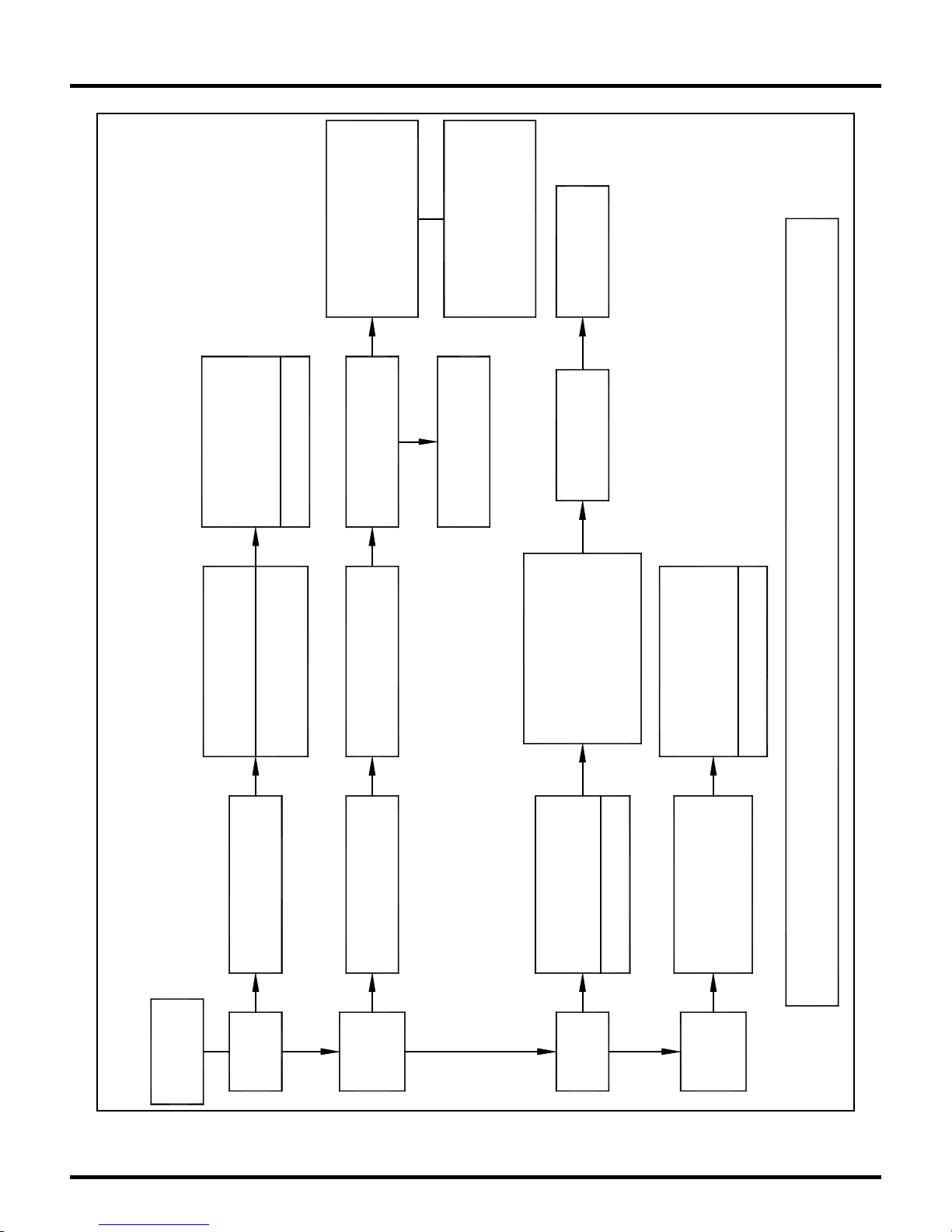
Troubleshooting Chart
Spin Freely?
Unplug Motor
Does Motor/Impeller
Verify at Motor
Check 120V Power
Replace Motor If
Rectify As Required
Required
Check For 24V At
Replace Ignition
Switch
Control Module
Rectify Transformer Or
Wiring As Required
Replace Valve
YES
Position?
Is Valve In On
YES
Valve During
Does 24V Occur At
As required
Verify Wiring
Verify Sense Electrode
Verify Ground
Rectify As Required
Wiring and Rectify
Ignition Trial? Check
Switch
NO
Is Pressure Switch
Check Electrode Gap
Check Burner System
Operating?
Set to 1/8"
For Obstruction
YES
Check Air Lines To
TROUBLESHOOTING CHART
Check Thermostat
Replace If Required
NO
Blower
Turn Up
Thermostat
Series-LA/LX/LXR Page 28 6/15/2010
Starts?
YES
Does
Check Ignition Wire
NO
Electrode
Replace If Damaged
Spark?
YES
YES
Valve? Is Gas
Is Gas Present At
NO
Burner
Pressure Sufficient?
Lights?
NO
YES
IF PROBLEM PERSISTS CONTACT YOUR LOCAL SRP REPRESENTATIVE
Is There A Flame
NO
Burner
Signal To Module?
Min. 0.8 Micro Amps
Lit?
YES
Stays
Rectify As Required
YES
Page 31
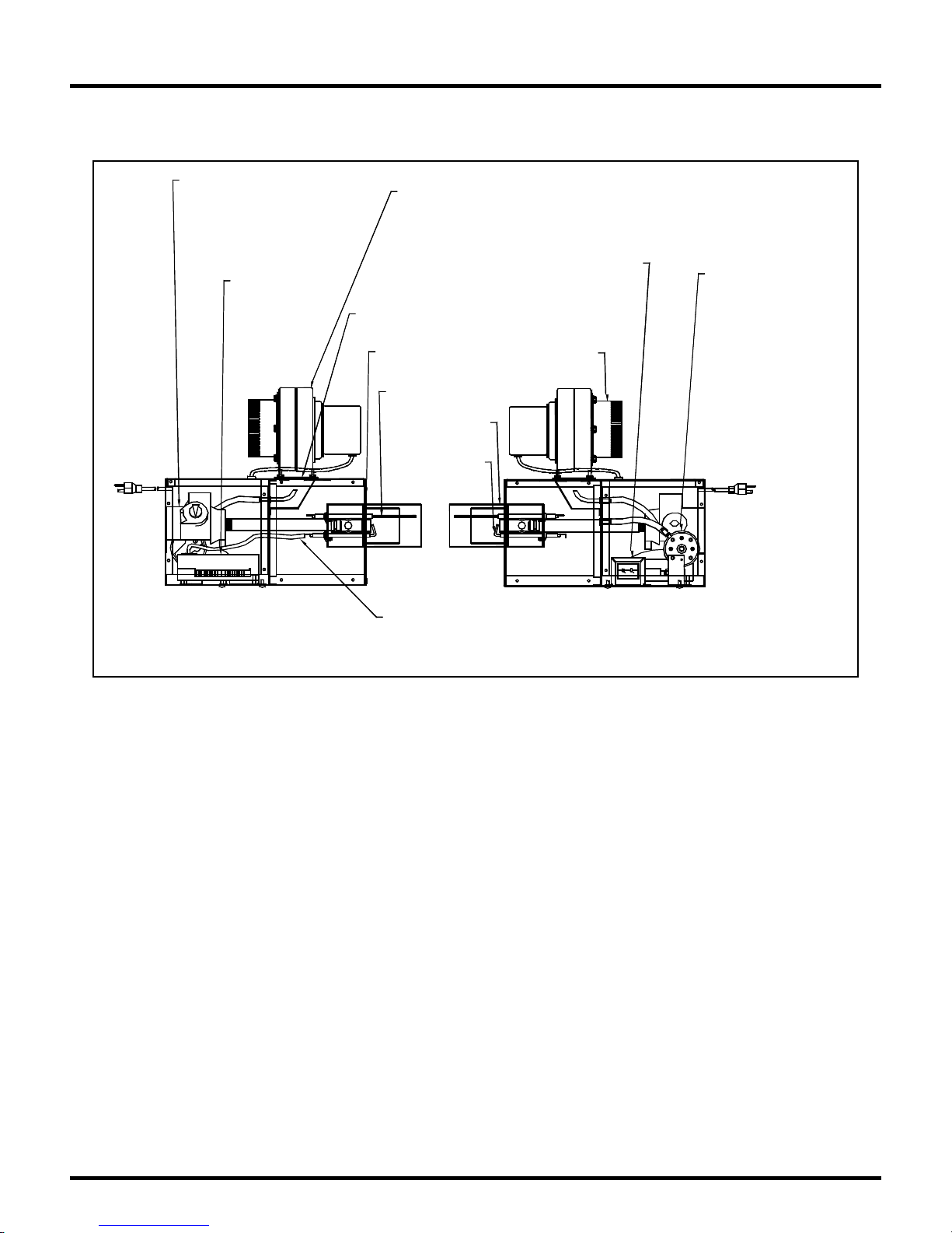
Replacement Parts
GAS VALVE,
- HONEYWELL P/N CG003 NAT.
- HONEYWELL P/N CG010 LP.
- WHITE RODGERS P/N CG060 NAT.
- WHITE RODGERS P/N CG061 LP.
IGNITION MODULE
P/N CE015
BLOWER GASKET
P/N CH 0 07
LA/LX INDICATO R LIGHT (NOT SHOWN)
YELLOW P/N CE057 ( ROUND)
MOTOR/BLOWER
(Models with 40,000 - 80,000 Btu input) - CE004
(Model with 10 0,0 00 Bt u i np ut) - CE 013
Models LA LX (40 VA) CE058
BURNER GASKET
P/N CH001
SENSE ELECTRODE
P/N LE002
BURNER CUP
P/N LG004
SPARK
ELECTRODE
P/N LE001
IGNITION LEAD
P/N CE006
TRANSFORMER
AIR INLET KIT
P/N VS022
PRESSURE SWITCH
LA/LX -40 CE025
LA/LX -60 CE025
LA/LX -80 CE025
LA/LX-100 CE0142
* LXR MODELS USE THE
SAME PARTS AS LX MODELS
Figure 30
Series-LA/LX/LXR Page 29 6/15/2010
Page 32
Notes
Series-LA/LX/LXR Page 30 6/15/2010
Page 33
d
Warranty
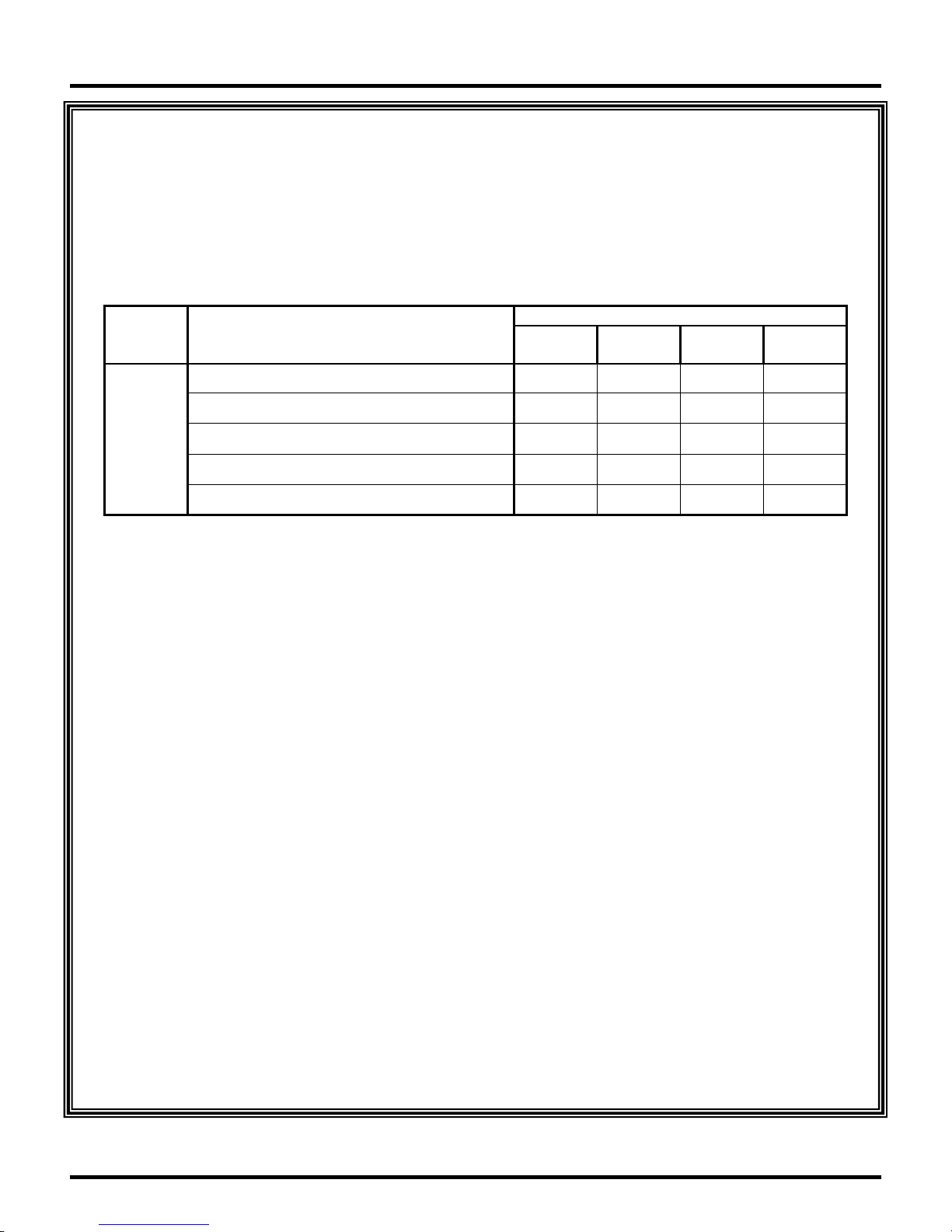
SERIES LA, LX and LXR INFRARED HEATERS
WARRANTY
The manufacturer warrant s to the original owner that the product will be free of defects in material
and workmanship as described below.
Warranty Perio
Series Component
Burner & Controls *
U,
T,
L,
LT
Hot Rolled Heat E xchanger w/o Post Purge *
Aluminized Heat Exchanger w/o Post P u rge *
Hot Rolled Heat E xchanger with Post Purge *
Aluminized Heat Exchanger with P ost Purge *
3
Years
5
Years
The Manufacturer’s obligation under this warranty is limited to repair or replacement, F.O.B. its
facility, of the defective part. I n the case of replacement part s, the warr anty period shall be the longer
of the original warranty or a period of 12 mo nths from the date o f purchase. In no event shall the
Manufacturer be liable for incidental expense or consequential damages of any kind.
This warranty does not cover any shipping, installation or other costs incurred in the repair or
replacement of the product. No materials will be accepted for return without author izat ion.
This warranty will not apply if in the judgment of the Manufacturer, the equipment has been
improperly installed, unreasonably used, damaged or modified.
This warranty will not apply to damage t o the product when used in corrosive atmospheres and in
particular atmospheres containing halogenated hydro carbons. No person is authorized to assume for
the Manufacturer any other warranty, obligation or liability.
7
Years
10
Years
THE REMEDIES PROVIDED FOR IN THE ABOVE EXPRESS WARRANTIES ARE THE SOLE
AND EXCLUSIVE REMEDIES. NO OTHER EXPRESS OR IMPLIED WARRANTIES ARE
MADE INCLUDING, BUT NOT LIMITED TO, ANY IMPLIED WARRANTY OF
MERCHANT ABILI TY OR FITNES S FOR A PART I CULAR USE OR PURPOSE.
Series-LA/LX/LXR Page 31 6/15/2010
 Loading...