

Page 1
OWNER’S MANUAL
INSTALLATION AND OPERATION
INSTRUCTIONS FOR
SUBMERSIBLE SUMP PUMPS
Models:
92250, 92260, 92251, 92255
92257, 92330, 92331, 92335
92337, 92341, 92342, 92351
92352, 92501, 92511, 92507
Superior Sump Manual Revised 10/08
Page 2
If for any reason you have questions concerning your new Superior Pump, call us toll free at
1-800-495-9278, or contact us on the web at www.superiorpumpco.com
Carefully read and understand all of the Warnings and installation instructions in this
manual. Failure to follow these instructions could lead to serious bodily injury and/or
property damage. Retain these instructions for future reference.
This pump has been manufactured with your needs in mind. Properly installed in the right
application, your new Superior Pump will give you years of carefree performance.
DANGER Water and electricity can be dangerous if certain precautions are not adhered
to. This pump is designed to operate perfectly safe in a water environment; however,
improper use and installation can result in personal harm from electrical shock. Please pay
attention to the following warnings.
WARNING
Never touch any electrical device, including this pump, when it is touching water, in water, or
even in a moist environment. Always unplug (disconnect the electricity) when working on or
installing the unit.
WARNING
RISK OF ELECTRICAL SHOCK. This pump is supplied with a grounding conductor and
grounding-type attachment plug. To reduce the risk of electrical shock, be certain that it is
connected only to a properly grounded, grounding-type receptacle.
WARNING Do not use the power cord or discharge hose to carry or handle the pump.
Doing so may cause damage to the power cord or discharge hose. Use the carrying handle
supplied with the pump.
WARNING Always use a grounded outlet. A three-prong mating type receptacle is
required for safe use. This should be in accordance with the National Electric Code and any
additional codes or laws required by your local government.
NOTICE It is strongly recommended to use a ground fault interrupt device on any
electrical appliance, including this pump, when used in a wet or moist environment as it
provides a much safer installation and will greatly reduce possible injury from electrical shock.
This is required by many local codes and enforcement agencies.
1
4
5
7
8
6
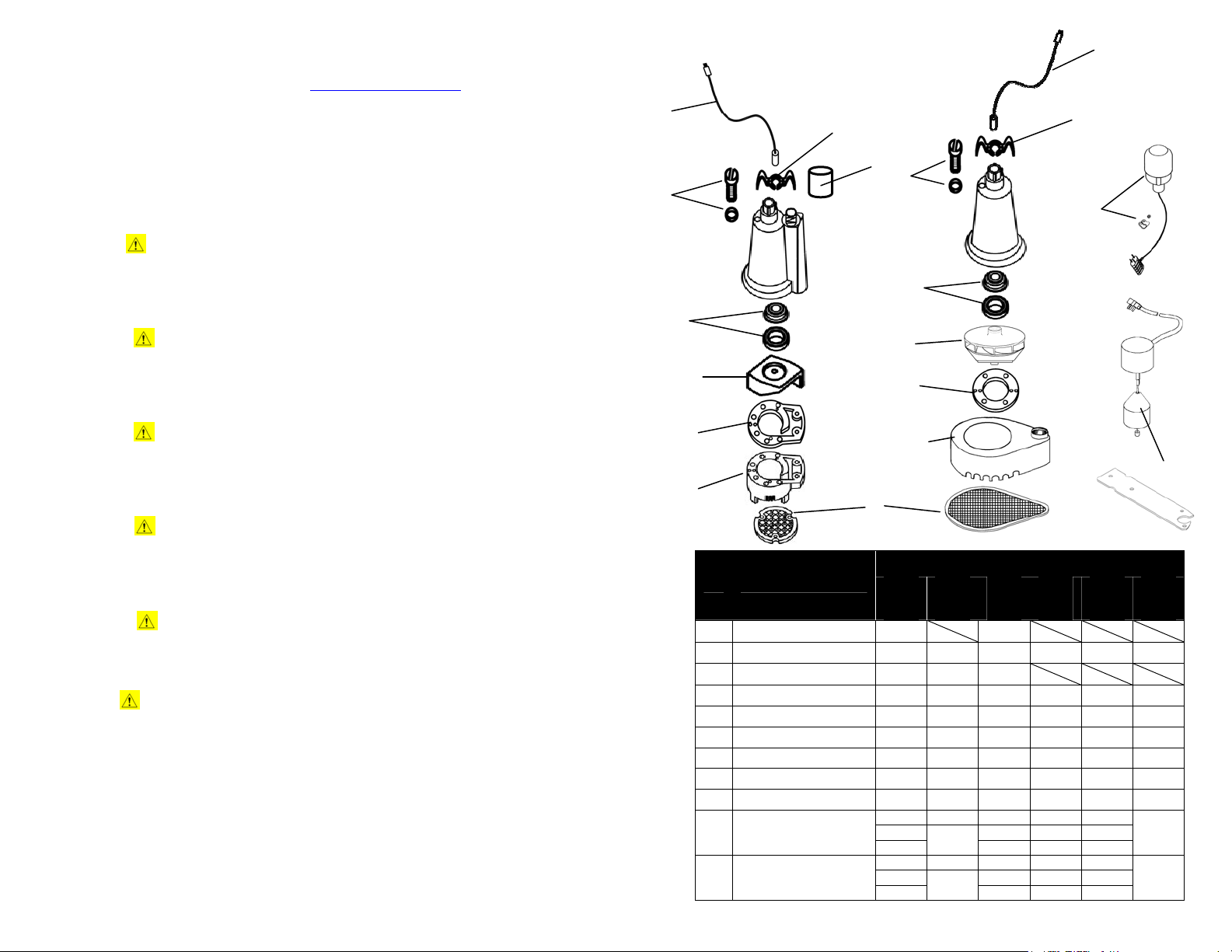
Ref Description
1 Power Cord 99008
2 Handle 99050 99051 99050 99051 99051
3 Hose Coupling/Adapter 99007 99007 99007
4 Oil Fill Plug with O-ring 99056 99056 99056 99056 99056
5 Shaft Seal 99057 99057 99057 99057 99057
6 Impeller 99060 99087 99065 99096 99070
7 Gasket 99062 99062 99062 99088 99064
8 Volute/Base 99067 99078 99069 99078 99071
9 Intake Screen 99073 99076 99073 99076 99074 99074
10 Float Switch
11 Vertical float Switch Bracket
REPLACEMENT PARTS
To order replacement parts,
Call 1-800-495-9278
2
3
4
5
6
7
8
9
92250
92255
92260
92000
92010
N/A
99105
92251
92257
92000 92000 92000 92000
92005
N/A
N/A
2 7
2
PARTS FOR MODEL#
92330
92342
92335
99008
92331
92341
92337
N/A
N/A
92010 92000
N/A
99105 N/A
N/A
92010
92005 92005 92005
99105
1
10
92351
92501
92507
N/A
N/A
10
11
92352
92511
99051
99056
99057
99070
99064
99071
92010 92000
99105 N/A
Page 3

NOTICE Height and/or piping restriction will reduce the pump output performance. See
the performance chart below to insure you have the proper pump for your application.
Whenever possible use the same size or larger pipe as the pump discharge for optimum
performance. Reducing the pipe size will not harm your pump; it will just reduce the output.
PERFORMANCES
DANGER Do not use this pump to pump chemicals, flammable liquids, sewage or
corrosive liquids. You could injure yourself and the pump will fail. Pumping these types of
liquids voids the warranty. Decko Products manufactures pumps for these types of liquids.
Make sure you purchase a pump designed for your specific needs. This pump will handle
fluids with the same characteristics as water. If you have any questions call us at
1-800-495-9278 or contact us on the web at www.superiorpumpco.com
Output in gallons per minute at listed discharge
Model #
0’ 5’ 10’ 15’ 20’ 25’
92250, 92251, 92260, 92255, 92257 30 22 20 16 9 2
92330, 92342, 92335 40 34 28 22 12 2
92331, 92337, 92341 46 36 30 25 12 1
92351, 92352 60 56 50 35 15 6
92501, 92511, 92507 70 66 58 48 25 10
height above pumping level
SPECIFICATIONS
92250
Model #
HP 1/4 1/4 1/3 .3 1/3 1/2
Amps 3.82 3.82 4.1 4.1 7.6 7.6
Solids Handling 1/8” 1/8” 1/8” 3/8” 1/2” 1/2”
Warranty
(Years)
Discharge Size 1 ¼” 1 ¼” 1 ¼” 1 ½” 1 ½” 1 ½”
Power supply requirements 120V, 60 Hz (15 amp)
Motor Continuous Duty, Capacitor Start,
Liquid Temperature Range 32° F - 120° F (0° C - 49° C)
92255
92260
1 3 1 3 3 3
92251
92257
92330
92342
92335
Thermally Protected
92331
92341
92337
92351
92352
92501
92511
92507
WARNING
Your pump has thermal over-loa
liquids over 120 F. The thermal overload protector will automatically shut down the pump in
an overheat situation. It will then reset itself once the pump cools down. This overload is
designed as a safety device and it will fail after repeated use. Normal operation is for fluids
between 32 F & 120 F.
DO NOT RUN THE PUMP DRY. The pump depends on water for cooling and lubrication.
Operating the pump without water may cause the motor to overheat or cause damage to parts
of the pump. It may also shorten the life of your pump.
d protection built in. It is not recommended for pumping
NOTICE
EXTENSION CORDS
For best performance, it is recommended to connect the power cord directly to the grounded
GFCI outlet. If the use of an extension cord is necessary, always use a grounded waterproof
type cord. Never use longer than a 25-ft. cord that is lighter than 14/3 gauge.
DANGER Keep all electrical connections away from wet and moist environm ents. Wet
connections can cause electrical shock resulting in personal injury.
USE AND INSTALLATION
WARNING ALWAYS DISCONNECT THE POWER SOURCE BEFORE ATTEMPTING TO INSTALL,
SERVICE OR PERFORM MAINTENANCE ON THE PUMP
ELECTRICAL SHOCK
Your Superior Pump is designed and built to give you reliable performance and long life. It will
pump water auto
.
matically for years when properly installed in the right environment.
. FAILURE TO DO SO MAY RESULT IN FATAL
REMOVING OLD PUMP. (If necessary)
1. Make sure power supply is disconnected.
2. After the power is off, remove
types of insta
3. It is best to remove all old p
debris and dirt out of the sump basin before insta
Be sure to have a grounded 120V AC outlet mounted within 6 ft. of your sump basin. Again,
is highly recommended that a GFCI (ground fault circuit interrupter) outlet be installed in the
receptacle box.
llati
ons.
the old pump. There are many different possibl
iping and start over with new piping. Be sure to clean a
lling your new pu
mp.
it
e
ll
NOTICE A qualified electrician must perform all wiring.
6 3
Page 4

INSTALLATION (New Pump)
A
1. Set your new pump in the bottom of the sump basin off to one side. The pump should be
placed on a solid foundation. Do not place the pump directly on the ground or sandy or
rocky surfaces. Sand and small stones may clog or cause damage to your pump.
2. Make sure the float switch will swing freely from the bottom to top without coming in
contact with the side of the sump basin. Contact with the side of the sump basin may
cause the switch to malfunction. See figure below.
Wide Angle Switch Installations
. Grounded Outlet. A GFCI outlet
is strongly recommended.
B. Full-flow swing type check valve
C. Discharge Pipe
D. Sump basin. Min. 14” diameter
E. Position pump so the float switch
operates freely without touching
the sides of the basin.
3. It is highly recommended to install a full flow, swing type check valve (not included)
as close to the discharge outlet on the pump as possible. A new check valve will
greatly increase the life of your pump. The check valve should be the same size as
Vertical Switch Installations
PROBLEM POSSIBLE CAUSES HOW TO CORRECT
If the pump does not
start or run
The pump starts and
stops too often
If the pump runs but
moves little or no water
TROUBLESHOOTING
Pump is not plugged in, switch or
breaker is off
Check for blown fuses or tripped circuit
breakers or tripped GFCI outlets
Float switch is defective Check and replace if necessary
Motor thermal protector tripped Allow pump to cool. Pump will reset
Float switch is stuck or obstructed
Backflow of water from discharge
hose/pipe
Float switch is defective Replace float switch
Clogged intake screen Clean or replace screen
Clogged discharge hose/pipe Remove clog
Frozen discharge hose/pipe Allow hose/pipe to thaw
Pump is air locked
Low line voltage
Check valve is stuck in the closed
position
Check valve is installed backwards
Worn, damaged or clogged pump parts
the pump discharge.
4. Connect the pump and check valve together using schedule 40 PVC pipe and
fittings. You can also use DWV or ABS pipe, as this is not a pressure installation.
Corrugated drain hose is intended for temporary use and should not be used in a
permanent installation. Although there are many types of pipe that work adequately
Pump does not
shut off
Discharge head exceeds pump
capacity
Float switch is obstructed or stuck Remove obstruction
Defective Float Switch Replace switch
for this installation, PVC is recommended.
5. Test your installation after you have completed setting up the pump. Plug the cord
from the pump into the piggyback plug of the float switch, then plug that into your
grounded outlet. The pump should not run at this point. If the pump runs, the
switch is stuck in the upright position or the pump is plugged directly into the outlet
and not through the piggyback switch plug. Fill the sump basin with water using
buckets or a hose. When the switch floats to the upright position, the pump will turn
on. The switch will turn off the pump when it reaches the down position. You may
adjust the switch to meet your particular needs. Remember the switch must swing
freely without touching the sides of the sump basin. NOTE: The cut out (turn off)
setting is the only adjustment available on vertical type switches.
4 5
Plug pump in or turn on
switch/breaker
Replace fuse, reset breaker, reset
GFCI outlet
Remove obstruction or position pump
so it will not become stuck
Install or replace check valve
Clean out airlock hole with a paper
clip or pipe cleaner
Check wire size and increase if
necessary
Inspect, repair or replace if necessary
Make sure check valve is installed in
the correct direction of flow
Inspect for wear, damage or clog and
clean or replace if necessary
If pumping height is over 25’, the
pump will not move water. See
performance chart
 Loading...