

superior fires F500453, F500456, F500455, F500454, F500457 Installation And User Instructions Manual
...
INSTALLATION & USER INSTRUCTIONS
Please note : All colour/finish variants are not shown.
All instructions must be handed to the user for
safekeeping.
MODELS COVERED BY THESE INSTRUCTIONS
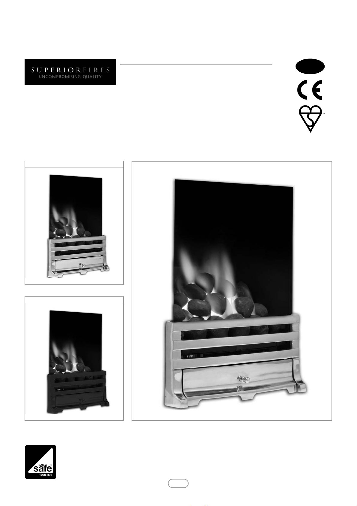
FULL DEPTH INSET DECORATIVE GAS FIRE
Please note : Except where otherwise stated, all rights, including
copyright in the text, images and layout of this booklet is owned by
Focal Point Fires plc. You are not permitted to copy or adapt any of
the content without the prior written permission of Focal Point Fires
plc.
1
Revision A - 12/11
© 2011 Focal Point Fires plc.
GB IE
BS EN 509 : 2000
KM579168
SONORA GROVE BRASS MANUAL CONTROL NG F500452
SONORA GROVE CHROME MANUAL CONTROL NG F500453
SONORA GROVE BLACK MANUAL CONTROL NG F500454
SONORA GROVE BRASS REMOTE CONTROL NG F500455
SONORA GROVE CHROME REMOTE CONTROL NG F500456
SONORA GROVE BLACK REMOTE CONTROL NG F500457
SONARA BLENHEIM MANUAL NG F500458
SONARA ELEGANCE MANUAL NG F500459
SONARA ELYSEE MANUAL NG F500460
SONARA BLENHEIM REMOTE CONTROL NG F500461
SONARA ELEGANCE REMOTE CONTROL NG F500462
SONARA ELYSEE REMOTE CONTROL NG F500463
Superior Fires
Christchurch, Dorset BH23 2BT
Tel: 01202 588 632
Fax: 01202 499326
www.superiorfires.co.uk
e : info@superiorfires.co.uk
SONORA GROVE BRASS
IN THE UK ALWAYS USE A GAS SAFE REGISTERED ENGINEER TO INSTALL, REPAIR OR SERVICE THIS APPLIANCE
SONORA GROVE CHROME
SONORA GROVE BLACK

• This appliance is an Inset Decorative Fuel Effect appliance which provides radiant warmth utilising the latest type
burner technology.
• The fire is designed to suit various types of fireplaces and natural draught flues as detailed in this manual.
• The appliance must be installed by a competent person in accordance with Gas Safety (Installation and Use)
Regulations 1998. It is strongly recommended that a GAS SAFE registered engineer be used for this purpose.
• Read all these instructions before commencing installation.
• This appliance must be installed in accordance with the rules in force and used only in a sufficiently ventilated
space.
• The appliance is designed for installation on to a non-combustible hearth of at least 300mm depth.
• This appliance is factory set for operation on the gas type, and at the pressure stated on the appliance data plate.
• In the event of gas leakage from the appliance, the gas supply must be turned off at the nearest isolating valve.
• The appliance must be installed in accordance with the following:
• Failure to comply with the above could lead to prosecution and deem the manufacturer’s warranty invalid.
• The appliance is designed to fit various types of situations as described in sections 3.0 and 4.0.
• It should be noted that heaters create warm air currents. These currents move heat to wall surfaces next to the
heater. Installing the heater next to vinyl or cloth wall coverings or operating the heater where impurities in the air
(such as tobacco smoke, candle smoke etc.) exist, may cause the walls to become discoloured.
• WARNING: The manufacturer of this appliance considers all surfaces as working surfaces with the exception of
the control knob and ash pan door. Where young children, pets, the elderly or infirm are concerned, a suitable fireguard should be used.
• Consult ALL instructions before installation and use of this appliance.
• This appliance is intended for decorative purposes.
• This appliance is free from any asbestos material.
• Refractories and fuel bed are constructed from ceramic fibre.
1.0 IMPORTANT NOTES
INSTALLATION INSTRUCTIONS
© 2011 Focal Point Fires plc.
2
GB IE
• Manufacturers' Instructions.
• The Building Regulations issued by the Department for Communities and Local Government, the Building Standards
(Scotland)
(Consolidation) Regulations issued by the Scottish Development Department.
• Relevant British Standards insofar as the relevant areas are not covered by these instructions.
• For Republic of Ireland, reference should be made to the current edition of IS813 (the relevant standards governing
installation).
Section
1.0
2.0
3.0
4.0
5.0
6.0
6.1
7.0
8.0
9.0
10.0
11.0
11.1
Contents
Important Notes
Appliance Data
Installation Requirements
Site Requirements
Ventilation
Unpacking the Appliance
Component Checklist
Installing the Burner
Fuel Bed Layout
Fire Front
Testing & Commissioning
Operating the fire
(Manual Models)
Operating the fire (Remote Models)
Page No.
2
3
3
3
4
4
4
4
5
5
5
5
5
Section
12.0
12.1
12.2
12.3
12.4
13.0
13.1
13.2
13.3
13.4
13.5
14.0
Contents
Spark Gap
Operating Pressure
Flue Spillage Monitoring System
Testing For Spillage
Briefing the Customer
Servicing
Cleaning the Ceramics
Removing the Burner
Servicing the Burner
Pilot Assembly
Replacing the Batteries (Remote control versions)
Troubleshooting Guide
User Guide
Page No.
6
6
6
6
7
7
7
7
7
7
8
8
2.0 APPLIANCE DATA
3
Model
Destination
Country
Cat
Operating Pressure
(±2.0 mbar)
Max Energy Input (kW) Min Energy Input (kW)
Natural gas
G20 G25 G30 G31 Gross Net Gross Net
Sonora
GB - IE
I
2H
20 -
- - 6.8 6.1 3.5 3.15
GB IE
© 2011 Focal Point Fires plc.
3.0 INSTALLATION REQUIREMENTS
This appliance MUST NOT be installed into a room containing a bath or shower, or where steam may be present. The fire has
been designed to fit into a builders’ opening or fireplace conforming to BS 1251 (and meeting certain dimensional requirements),
or a suitable flue box complying with the constructional requirements of BS 715. Either a ‘Replacement Chairbrick’ or a BS 1251
chairbrick should also be fitted into the builders’ opening. The flue box must be installed onto a suitable non-combustible insulating surface at least 12mm thick, covering the entire base are of the box.
The flue must have an effective height of at least three meters, as measured from the hearth to the top of the flue. Any flue damper
plates or restrictors should be removed and no other restriction fitted to the flue. Where removal is not practical, the restriction must be fixed in the fully open position. A natural draught flue system is required, and if previously used for solid fuel or oil
burning, the flue and chimney must be swept prior to appliance installation. The flue must be checked before installation by using
a smoke pellet or similar to ensure proper draw and that leakage is not evident at any joints. Repair and re-test as necessary
before the appliance is installed. The flue must be connected to only one fireplace, and the flue must not vent more than one appliance (i.e. not shared with a gas back boiler). There must be no opening in the flue apart from the one that the appliance is installed
into, and the one venting the gases into the air. A suitable terminal may be fitted, such as class GC1, as regulations allow.
This appliance has been tested for use with circular flues of a minimum internal diameter of 175mm. The flue termination (cowl)
must be of a type suitable for use with an inset Decorative Fuel Effect Fire BS5871 part 3 contains further details.
The fireplace opening should be inspected and repairs made where necessary. Any chair brick may be left in place.
The opening WIDTH and HEIGHT dimensions should be between
405mm and 440mm wide, and 565mm to 575mm high.
Opening DEPTH should be 220mm or greater. Opening DEPTHS
include any plaster or infill panels which form part of the installation.
This appliance requires a natural draught flue system which may be one
of the following;
• 225mm x 225mm (9in x 9in) brick or stone.
• 175mm (7in) minimum diameter lined brick or stone.
• 175mm (7in) minimum diameter twin wall flue conforming to BS 715.
Any existing under grate draught device must be sealed off.
The opening wall must be non-combustible.
The appliance requires a hearth with
non-combustible surface of at least
12mm thick.
The top surface must be at least 50mm
above the surrounding floor level, or be
surrounded by a raised edge or fender
50mm high.
Specifications Manual control models Manual control models
Main burner injector Stereo size 76 Stereo size 76
Oxypilot SIT 9081 SIT 9081
Gas Control Copreci 21400/342 Mertik Maxitrol GV30 series
Gas Inlet 8mm compression - Inlet restrictor elbow 8mm compression - Inlet restrictor elbow
Ignition Piezo Spark Piezo Spark
Spark Gap 3.5 - 4.5mm 3.5 - 4.5mm
Flue specification
225mm x 225mm (9in x 9in) brick or stone.
175mm (7in) minimum diameter lined brick or stone.
175mm (7in) minimum diameter twin wall flue conforming to BS 715.
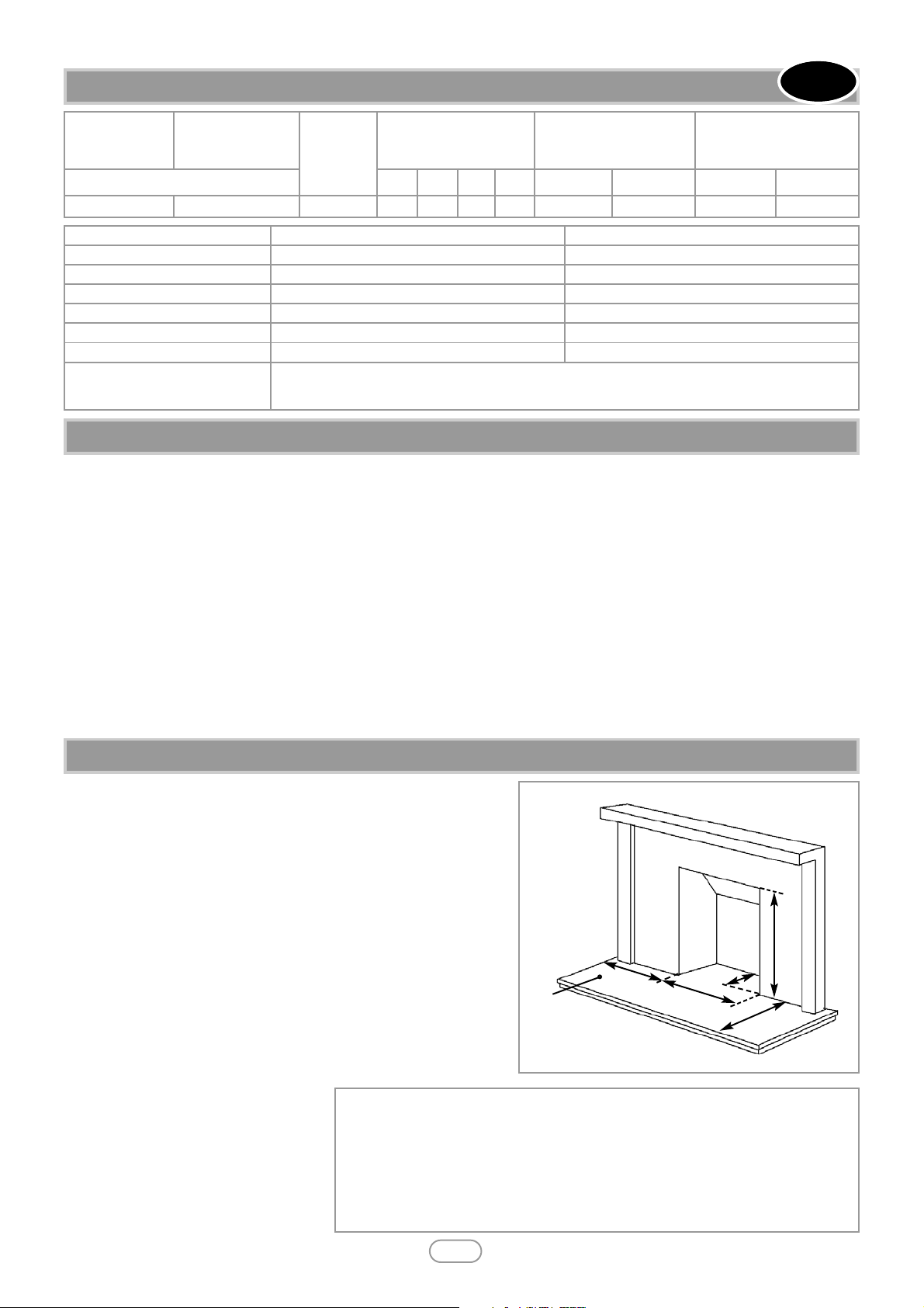
4.0 SITE REQUIREMENTS
A. Opening height: 565mm min/575 mm max.
B. Opening width: 405mm min/440mm max.
C. Mounting depth: 220mm
D. Hearth must extend minimum of 150mm either side of the opening.
E. Hearth must extend minimum of 300mm in front of the opening.
F. Non-combustible hearth must be a minimum of 50mm in height, or be surrounded by a 50mm high fender.
‘A’
‘B’
‘C’
‘D’
‘E’
‘F’
Figure 1

4.0 SITE REQUIREMENTS - CONTINUED
Any type of fire surround used with this appliance must be adequately sealed to the wall and floor.
A combustible shelf may be fixed to the wall above the fire, providing that it complies with the dimensions given below.
A non-combustible shelf may be fitted to within 10mm of the top edge of the fireplace opening.
Combustible materials, such as wood, may be fitted to within 100mm (4in) of either side of the fireplace opening , providing the
forward projection does not exceed 100mm (4in).
Any combustible side walls must be at least 500mm to the side of the radiant heat source.
As with all heating appliances, any decorations, soft furnishings, and wall coverings (i.e. flock, blown vinyl and embossed paper)
positioned too close to the appliance may discolour or scorch.
No purpose provided ventilation is normally required for this appliance. The requirements of other appliances operating in the
same room or space must be taken into consideration when assessing ventilation.
If spillage is detected when commissioning the appliance then amongst other problems there may be insufficient natural ventilation for the correct operation of the flue. This is potentially a greater problem should the property be of modern nature. If the
appliance does not spill with windows open but does with windows closed, this proves that lack of ventilation is the problem, if
not, it will be the flue at fault. Installation of an air brick in these circumstances may be the best solution. Any ventilation fitted
must comply with BS 5871 part 2 and BS 5440 part 2. Ventilation located underneath or within the immediate vicinity (one metre)
of the fire MUST NOT be used as it may adversely affect the performance of the O.D.S. system.
Spillage detected during commissioning is almost always a result of poor flue performance, which cannot be corrected by any
amount of ventilation. For Republic of Ireland ventilation may be required, see IS 813, ICP3, IS 327, and any other rules in force.
Read all the instructions before continuing to unpack or install this appliance.
Remove the box containing the firefront, and the bag containing the coals. Remove the cardboard packing pieces, and any bags
containing other fittings or parts. Remove the burner unit from the remaining packaging.
Check that the components supplied correlate with the checklist given in section 6.1. Please dispose of the packaging materials
at your local recycling centre.
Note: Ensure that the gas supply is isolated before commencing installation of the appliance.
Smoke test the flue to ensure proper draw and that there are no leaks present.
Locate the gas supply point. This appliance is suitable for all gas connections, including those concealed behind the opening.
Important Note: Check that the thermocouple connection nut into the rear of the valve is secure.
Place the appliance into the shaped firebrick, ensuring it does not protrude forward of the fireplace opening. Mark the location
of the front support of the tray. Remove the tray and drill the two marked holes with an appropriate masonry bit. Place wall plugs
into the holes. Remove the front support from the appliance by unscrewing from the two front legs. Position the front foot in the
over the holes and secure the front support using suitable screws into the prepared holes. Re-fit the tray into the shaped firebrick, and secure the front legs of the tray to the support.
Using 8mm diameter pipe, connect the appliance to the gas supply point. The appliance must be fitted with rigid or semi-rigid pipe
of 8mm external diameter. The appliance is factory fitted with an inlet restrictor elbow.
Use a minimum length of 8mm pipe, less than 1.5m where possible, as a long run of pipe may cause an unacceptable drop in the
supply pressure.
GB IE
4
© 2011 Focal Point Fires plc.
5.0 VENTILATION
6.0 UNPACKING THE APPLIANCE
6.1 COMPONENT CHECKLIST
QUANTITY DESCRIPTION
1 Burner tray assembly.
1 Cast firefront with separate ashpan cover.
1 Moulded ceramic fibre combustion matrix.
16 Individual ceramic coals (coal models only)
16 Individual ceramic pebble (pebble models only)
9 Individual ceramic logs (log models only)
1 Moulded ceramic front strip.
1 Set of manufacturers instructions.
1 Remote control handset (remote control models only)
1 Screw pack.
7.0 INSTALLING THE BURNER
Maximum depth of shelf Minimum distance from finished hearth surface to underside of shelf
100mm 745mm
150mm 845mm
203mm 895mm
Please refer to the relevant section of the user manual.
Unwrap the firefront and ashpan door. Place the firefront directly in front of the fire and slide the ashpan door into place.
Do not use any firefront other than the one supplied with the appliance.
Turn on and test the gas supply up to the fire for any leaks, in accordance with current edition of BS6891.
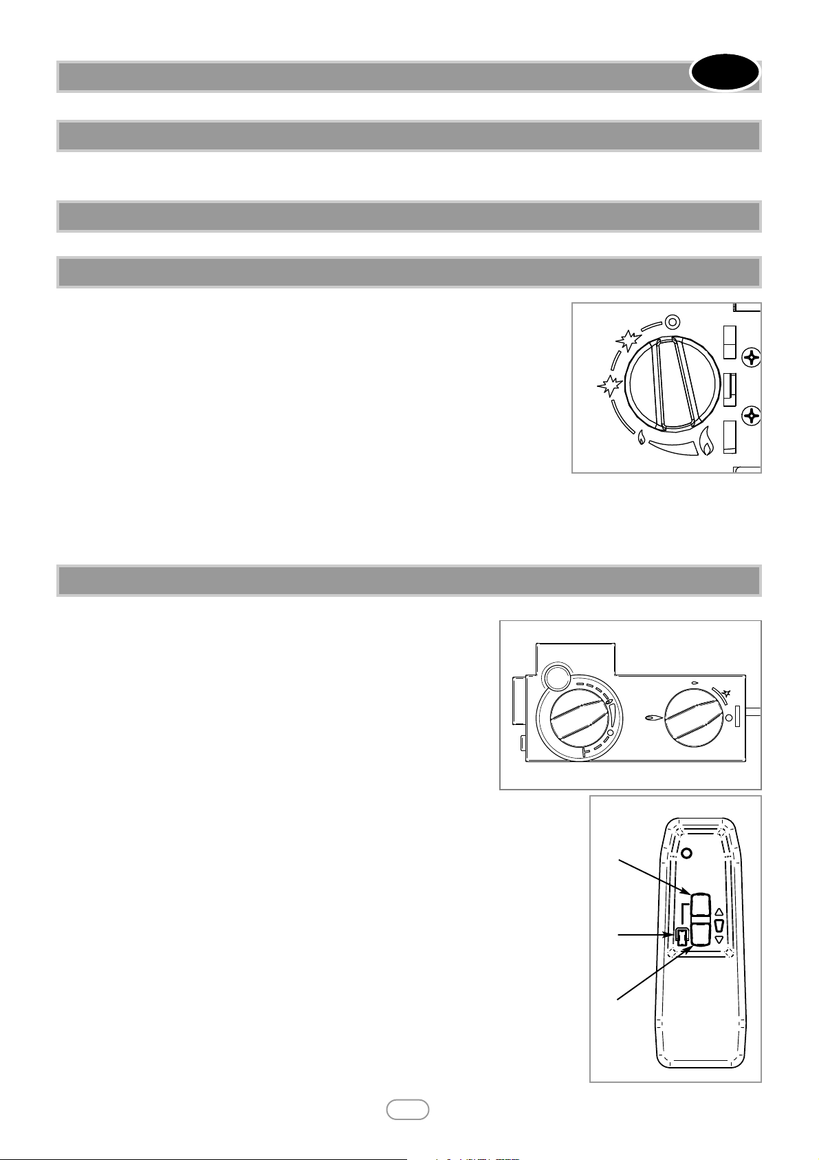
The pilot is visible through the left hand side of ceramic fuel matrix. When cold, the coals or
pebbles may be rotated for good viewing. The fire features a ‘twin spark’ ignition system to
aid lighting, Push the control knob in fully and turn anti-clockwise through both of the
SPARK positions, keeping fully depressed, hold there for a few seconds. If the fire has not
been used for some time, hold the knob in this position for longer, to allow any air in the
pipes to be purged.
Ensure the pilot has lit. If not, return the knob clockwise, and repeat. When the pilot lights
after one of the two sparks, keep the knob depressed in the nine o’clock position for
approximately ten seconds. Now release the knob and the pilot should stay alight. If the pilot
is extinguished during use, wait three minutes before repeating the ignition procedure.
To achieve the HIGH setting, push the control knob in slightly and continue turning anticlockwise to the high position. The main burner should light after a few seconds. To decrease the setting to LOW, push the knob
in slightly and turn the control knob clockwise to the low setting. To turn to the pilot only position from the HIGH or LOW positions, press the control knob in, and return to the nine o’clock position and release. To turn the fire OFF, keep the knob pressed
in, return to the off position and release.
The pilot is visible through the left hand side of ceramic fuel matrix. When cold,
the coals or pebbles may be rotated for good viewing. Turn the main burner
control (shown in figure 3 on left hand side of control valve) knob fully anticlockwise.
Turn ignition knob (shown on right hand side of control valve) slightly left
towards the ignition position until reaching the stop, press down and hold for
5 seconds (only pilot gas is flowing).
Continue pressing down the knob while turning further to the left to activate
the piezo spark, continue to hold the knob down for a further 10 seconds after
the pilot has been lit. If the pilot does not light repeat the previous steps.
Upon lighting and after the further 10 seconds, release the knob and turn further to the left to the ON position. The main burner will light and be controlled in accordance
with the main burner control knob setting. Adjust the main burner control knob to the desired
setting.
If the pilot is extinguished during use of the fire, you MUST wait ten minutes before repeating
the ignition procedure.
To turn the main burner OFF whilst keeping the pilot flame lit, turn the ignition control knob
to the pilot position then only the pilot will remain lit.
To shut the fire off completely, press the ignition control knob down and continue turning to
the right from the pilot position to the OFF position.
A safety interlock prevents re-ignition of the pilot flame until the thermocouple has cooled sufficiently to allow the magnetic valve unit to reset itself.
The remote control unit allows operation of the main burner setting between maximum and
pilot only setting. It does not permanently turn the pilot on or off.
The remote control handset incorporates an inbuilt safety feature to prevent the main burner
being activated or turned up accidentally. It is necessary to press buttons 1 and 2 (see figure 4)
simultaneously to turn the fire up.
To turn the fire down press button 3 only.
8.0 FUEL BED LAYOUT
5
© 2011 Focal Point Fires plc.
GB IE
9.0 FITTING THE FIREFRONT
10.0 TESTING AND COMMISSIONING
11.0 OPERATING THE FIRE (MANUAL CONTROL MODELS)
Figure 2
11.1 OPERATING THE FIRE (REMOTE CONTROL MODELS)
1
2
3
Figure 3
Figure 4
 Loading...