

Superior Fireplaces VRT4032WH, VRT4036RS, VRT4036WS, VRT4036WH, VRT4032RS Installation And Operation Instructions Manual
...
Installation and Operation Instructions
PFS
US
SuperiorTM Unvented (Vent-Free) Universal Firebox
P/N 126709-01 Rev.A 02/2014
P126709-01
Models
®
VRT4032WS
VRT4032WH
VRT4032RS
VRT4032RH
VRT4036WS
VRT4036WH
VRT4036RS
VRT4036RH
VRT4042WS
VRT4042WH
VRT4042RS
VRT4042RH
INSTALLER: Leave this manual with the appliance.
CONSUMER: Retain this manual for future reference.
WARNING: Carefully review the instructions supplied with the decorative type unvented room heater for
the minimum fireplace size requirement.
Do not install the appliance in this firebox, unless this firebox meets the minimum dimensions required for
the installation.
WARNING: For use only with a listed, gas-fired unvented decorative room heater not to exceed 40,000
Btu/H.
Do not build a wood fire.
WARNING: If the information in these instructions is not followed exactly, a fire or explosion may result
causing property damage, personal injury or loss of life.
— Do not store or use gasoline or other flammable vapors and liquids in the vicinity of this or any other
appliance.
— WHAT TO DO IF YOU SMELL GAS:
• Do not try to light any appliance.
• Do not touch any electrical switch; do not use any phone in your building.
• Immediately call your gas supplier from a neighbor’s phone. Follow the gas supplier’s instructions.
• If you cannot reach your gas supplier, call the fire department.
— Installation and service must be performed by a qualified installer, service agency or the gas supplier.

WARNING: Improper installation, adjustment, alteration, service or maintenance can cause injury or
property damage. Refer to this manual for correct installation and operational procedures. For assistance
or additional information consult a qualied installer,
service agency or the gas supplier.
TABLE OF CONTENTS
Safety .................................................................. 2
Local Codes......................................................... 3
Product Features ................................................. 4
Locating Firebox .................................................. 4
Product Specications ......................................... 5
Air For Combustion and Ventilation ..................... 7
Installation ........................................................... 9
Replacement Parts ............................................ 14
Technical Service............................................... 14
Accessories ....................................................... 15
Parts .................................................................. 16
Warranty ............................................................ 20
SAFETY
This appliance may be installed
in an aftermarket,* permanently
located, manufactured (mobile)
home, where not prohibited by
local codes.
* Aftermarket: Completion of sale, not for
purpose of resale, from the manufacturer
This firebox has been tested
under Z21.91b-2007 for use
with approved ANSI Z21.11.2
decorative type unvented room
heater.
WARNING: Any change to
this rebox or its controls can
be dangerous.
WARNING: Do not use a
blower insert, heat exchanger
insert or other accessory not approved for use with this rebox.
www.SuperiorFireplaces.US.com
IMPORTANT: Read this owner’s
manual carefully and completely
before trying to assemble, operate or service this replace.
Improper use of this replace
can cause serious injury or
death from burns, re, explosion, electrical shock and carbon
monoxide poisoning.
DANGER: Carbon monoxide
poisoning may lead to death!
WARNING: Do not allow fans
to blow directly into the rebox.
Avoid any drafts that alter burner
ame patterns. Ceiling fans can
create drafts that alter burner
ame patterns. Altered burner
patterns can cause sooting.
126709-01A2
SAFETY
Continued
Due to high temperatures, the
appliance should be located out
of trafc and away from furniture
and draperies.
Do not place clothing or other
ammable material on or near
the appliance. Never place any
objects in the rebox or on logs.
Firebox front and screen becomes very hot when running
rebox. Keep children and adults
away from hot surfaces to avoid
burns or clothing ignition. Firebox will remain hot for a time
after shutdown. Allow surfaces
to cool before touching.
Carefully supervise young children when they are in the room
with rebox.
Keep the replace area clear and
free from combustible materials,
gasoline, and other ammable
vapors and liquids.
You must operate this replace
with the provided fireplace
screen and hood in place. Make
sure these parts are in place
and screens are closed before
running installed gas log heater.
Replace hood with INNOVATIVE
HEARTH PRODUCTS model
109511-01 50", 109511-02 42",
or 109511-03 36" only. This hood
has been designed to keep the
operation of your replace safe
and efcient.
1. Do not use this rebox as a wood burning
replace. Use only decorative unvented
room heaters (log sets).
2. Do not add extra logs or ornaments such as
pine cones, vermiculite or rock wool. Using
these added items can cause sooting.
3. Use only the provided hood. See Parts,
page 18.The rebox canopy (hood) must
not be modied or replaced with a canopy
(hood) that may be provided with the
unvented decorative room heater.
4. Vent-free gas log heaters installed in these
reboxes require fresh air ventilation to
run properly. See Air for Combustion and
Ventilation, page 8.
5. Do not run vent-free heaters installed in
these reboxes
• where ammable liquids or vapors are
used or stored
• under dusty conditions
6. Do not use this rebox to cook food or
burn paper or other objects.
7. Turn unit off and let cool before servicing.
Only a qualied service person should
service and repair rebox.
8. Operating vent-free heaters installed in
these reboxes above elevations of 4,500
feet could cause pilot outage.
9. Do not use the rebox if it has been
under water.
10. Before using furniture polish, wax, carpet
cleaner or similar products, turn heater
off. If heated, the vapors from these prod-
ucts may create a white powder residue
within burner box or on adjacent walls
and furniture.
11. Provide adequate clearances around air
openings.
126709-01A 3
www.SuperiorFireplaces.US.com

LOCAL CODES
Install and use with care. Follow all local
codes. In the absence of local codes, use
the latest edition of The National Fuel Gas
Code, ANSI Z223.1/NFPA 54*. Firebox must
be electrically grounded in accordance with
the National Electrical Code, ANSI/NFPA70
(latest edition).
*Available from:
American National Standards Institute, Inc.
1430 Broadway
New York, NY 10018
National Fire Protection Association, Inc.
Batterymarch Park
Quincy, MA 02269
PRODUCT FEATURES
OPERATION
This rebox has been tested and approved
under ANSI Z21.91 for use with any gas
log approved to ANSI Z21.11.2 for indoor
applications and ANSI Z21.97 for outdoor
applications. (Physical size limitations apply.
Refer to minimum rebox requirements supplied with log heater.) It requires no outside
venting or chimney making installation easy
and inexpensive. When used without blower,
heater installed in rebox requires no electric-
ity making it ideal for emergency backup heat.
State of Massachusetts: The installation
must be made by a licensed plumber or
gas tter in the Commonwealth of Massachusetts.
Sellers of unvented propane or natural
gas-red supplemental room heaters shall
provide to each purchaser a copy of 527
CMR 30 upon sale of the unit.
Vent-free gas products are prohibited for
bedroom and bathroom installation in the
Commonwealth of Massachusetts.
REFRACTORY BRICK LINER
Your rebox may feature a concrete refractory
brick liner. As with all concrete liners, this liner
may develop slight cracks when exposed to
heat. These cracks will not affect performance
of replace or vent-free gas logs.
OUTSIDE AIR KIT ACCESSORY
An optional AK4 air kit provides additional
outdoor air to improve burner efciency and
reduce build-up of condensation in the living
space. Follow instructions included with air kit.
LOCATING FIREBOX
PLANNING
Plan where you will install the rebox. This will
save time and money later when you install
the rebox. Before installation, consider the
following:
1. Where rebox will be located: Allow for
wall and ceiling clearances (see Installa-
tion Clearances, page 10).
2. Everything needed to complete replace
installation.
www.SuperiorFireplaces.US.com
3. These models CANNOT be installed in
a bedroom unless maximum Btu rating
of installed vent-free log set is less than
10,000 Btu/hr.
4. Proper air for combustion and ventilation
(page 7).
126709-01A4

237/8"
39/16"
17
3
/8"
297/16"
34
7
/16"
36
3
/8" Indoor
37
3
/8" Indoor/Outdoor
Standoffs
227/16"
321/4"
361/2"
3
9
/16"
8
1
/8"
41/4"
Built-In
Side
Nailing
Flanges
5/8"
32" MODELS
237/8"
297/16"
34
7
/16"
36
3
/8" Indoor
37
3
/8" Indoor/Outdoor
Standoffs
227/16"
321/4"
361/2"
815/16"
93/4"
19 3/8 "
16 5/8"
19/16"
3
9
/16"
8
1
/8"
213/16"
85/8" Indoor
8
1
/4" Indoor/Outdoor
41/4"
Built-In
Side
Nailing
Flanges
Square
Gas Line
Access
Holes
5/8"
Left Side
View with
Air Kit
Outside Air
Kit Location
(Optional)
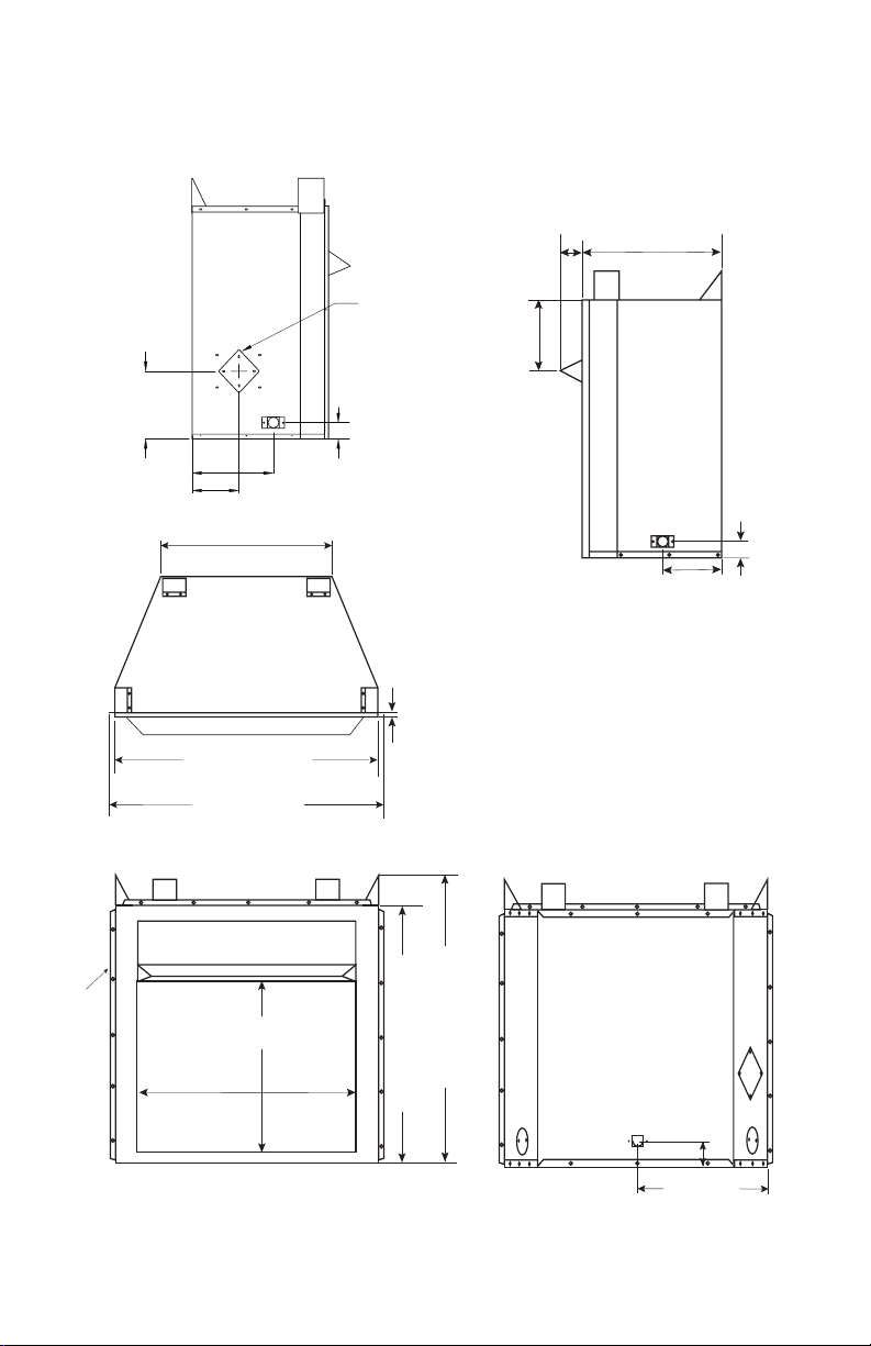
PRODUCT SPECIFICATIONS
1
/8"
8
1
10
/2"
1
8
/8"
7
3
/16"
Firebox Top View
3 9/16"
3
9
/4"
Top View
Front View
Figure 1 - Firebox Dimensions (32" Models)
Right Side View
Back View
126709-01A 5
www.SuperiorFireplaces.US.com
20 1/2"
(36" Models)
24
1
/8"
(42" Models)
9
/16"
2 9/16"
26
3
/4" (36" Models)
29
5
/8" (42" Models)
35" (36" Models)
42" (42" Models)
40" (36" Models)
44
1
/
4
" (42" Models)
43"(36" Models)
51
1
/8"(42" Models)
29
1
/8" (36" Models)
36
1
/8" (42" Models)
41
1
/8"(36" Models)
48
1
/4"(42" Models)
5/8"
36
1
/
8
" (36" Models)
40" (42" Models)
Built-In
Side
Nailing
Flanges
PRODUCT SPECIFICATIONS
13 11/16" (36" Models)
12
3
/8" (42" Models)
7 1/4" (36" Models)
9" (42" Models)
2 9/16"
10
1
/2"
(36" Models)
12
1
/2"
(42" Models)
13 11/16" (36" Models)
15
9
/16" (42" Models)
2
9
/16"
3
13
/16"
26
3
/4" (36" Models)
29
5
/8" (42" Models)
35" (36" Models)
42" (42" Models)
40" (36" Models)
44
1
/
4
" (42" Models)
43"(36" Models)
51
1
/8"(42" Models)
29
1
/8" (36" Models)
36
1
/8" (42" Models)
8
1
/8"
(36" Models)
9"
(42" Models)
21
1
/8" (36" Models)
23
1
/16" (42" Models)
41
1
/8"(36" Models)
48
1
/4"(42" Models)
5/8"
36
1
/
8
" (36" Models)
40" (42" Models)
Built-In
Side
Nailing
Flanges
Continued
36" AND 42" MODELS
Note: If only one dimension is shown, dimension is the same for both 36" and 42" models.
Left Side
View with
Air Kit
Top View
Front View
Figure 2 - Firebox Dimensions (36" and 42" Models)
Outside Air
Kit Location
(Optional)
Right
Side
View
Firebox Top View
www.SuperiorFireplaces.US.com
Back View
126709-01A6

AIR FOR COMBUSTION AND VENTILATION
WARNING: This heater shall
not be installed in a room or
space unless the required volume of indoor combustion air
is provided by the method de-
scribed in the National Fuel Gas
Code, ANSI Z223.1/NFPA 54, the
International Fuel Gas Code, or
applicable local codes. Read the
following instructions to insure
proper fresh air for this and
other fuel-burning appliances
in your home.
Today’s homes are built more energy efcient
than ever. New materials, increased insulation
and new construction methods help reduce
heat loss in homes. Home owners weather
strip and caulk around windows and doors to
keep cold air out and warm air in. During heating months, home owners want their homes
as airtight as possible.
While it is good to make your home energy
efcient, your home needs to breathe. Fresh
air must enter your home. All fuel-burning appliances need fresh air for proper combustion
and ventilation.
Exhaust fans, reboxes, clothes dryers and
fuel burning appliances draw air from the
house to operate. You must provide adequate
fresh air for these appliances. This will insure
proper venting of vented fuel-burning appliances.
PROVIDING ADEQUATE
VENTILATION
The following are excerpts from National Fuel
Gas Code, ANSI Z223.1/NFPA 54, Air for
Combustion and Ventilation.
All spaces in homes fall into one of the three
following ventilation classications:
1. Unusually Tight Construction
2. Unconned Space
3. Conned Space
Information on page 7 through 9 will help you
classify your space and provide adequate
ventilation.
Unusually Tight Construction
Air that leaks around doors and windows may
provide enough fresh air for combustion and
ventilation. However, in buildings of unusually
tight construction, you must provide additional
fresh air.
Unusually tight construction is dened as
construction where:
a. walls and ceilings exposed to outside
atmosphere have a continuous water
vapor retarder with a rating of one
perm (6 x 10
less with openings gasketed or sealed
and
b. weather stripping has been added on
openable windows and doors and
c. caulking or sealants are applied to
areas such as joints around window
and door frames, between sole plates
and oors, between wall-ceiling joints,
between wall panels, at penetrations
for plumbing, electrical and gas lines
and at other openings.
If your home meets all three criteria above,
you must provide additional fresh air. See
Ventilation Air From Outdoors, page 9.
If your home does not meet all
above, proceed to Determining Fresh-Air
Flow for Firebox Location, page 8.
Conned and Unconned Space
The National Fuel Gas Code, ANSI Z223.1/
NFPA 54 denes a conned space as a space
whose volume is less than 50 cubic feet per
1,000 Btu per hour (4.8 m3 per kw) of the aggregate input rating of all appliances installed
in that space and an unconned space as a
space whose volume is not less than 50 cubic
feet per 1,000 Btu per hour (4.8 m3 per kw)
of the aggregate input rating of all appliances
installed in that space. Rooms communicating
directly with the space in which the appliances
are installed*, through openings not furnished
with doors, are considered a part of the unconned space.
* Adjoining rooms are communicating only if
there are doorless passageways or ventilation
grills between them.
-11
kg per pa-sec-m2) or
three criteria
126709-01A 7
www.SuperiorFireplaces.US.com

AIR FOR COMBUSTION AND VENTILATION
Continued
DETERMINING FRESH-AIR FLOW
FOR HEATER LOCATION
Determining if You Have a Conned or
Unconned Space
Use this work sheet to determine if you have
a conned or unconned space.
Space: Includes the room in which you will
install heater plus any adjoining rooms with
doorless passageways or ventilation grills
between the rooms.
1. Determine the volume of the space (length
x width x height).
Length x Width x Height = ______cu. ft.
(volume of space)
Example: Space size 22 ft. (length) x 18
ft. (width) x 8 ft. (ceiling height) = 3168 cu.
ft. (volume of space)
If additional ventilation to adjoining room
is supplied with grills or openings, add the
volume of these rooms to the total volume
of the space.
2. Multiply the space volume by 20 to determine the maximum Btu/Hr the space can
support.
_____ (volume of space) x 20 = (Maxi-
mum Btu/Hr the space can support)
Example: 3168 cu. ft. (volume of space) x
20 = 63,360 (maximum Btu/Hr the space
can support)
3. Add the Btu/Hr of all fuel burning appliances in the space.
Vent-free heater _______ Btu/Hr
Gas water heater* _______ Btu/Hr
Gas furnace _______ Btu/Hr
Vented gas heater _______ Btu/Hr
Gas replace logs _______ Btu/Hr
Other gas appliances*
TotaL = _______ Btu/Hr
* Do not include direct-vent gas appli-
ances. Direct-vent draws combustion
air from the outdoors and vents to the
outdoors.
Example:
Gas water heater _________ Btu/Hr
Vent-free heater + ________ Btu/Hr
Total = ________ Btu/Hr
+ _______ Btu/Hr
40,000
39,000
79,000
4. Compare the maximum Btu/Hr the space
can support with the actual amount of
Btu/Hr used.
_________ Btu/Hr (maximum the space
can support)
_________ Btu/Hr (actual amount of
Btu/Hr used)
Example: 63,360 Btu/Hr (maximum
the space can support)
79,000 Btu/Hr (actual amount
of Btu/Hr used)
The space in the above example is a conned
space because the actual Btu/Hr used is more
than the maximum Btu/Hr the space can support. You must provide additional fresh air.
Your options are as follows:
A. Rework worksheet, adding the space
of an adjoining room. If the extra space
provides an unconned space, remove
door to adjoining room or add ventilation
grills between rooms. See Ventilation Air
From Inside Building, page 9.
B. Vent room directly to the outdoors. See
Ventilation Air From Outdoors, page 9.
C. Install a lower Btu/Hr heater, if lower
Btu/Hr size makes room unconned.
If the actual Btu/Hr used is less than the
maximum Btu/Hr the space can support, the
space is an unconned space. You will need
no additional fresh air ventilation.
WARNING: If the area in which
the heater may be operated does
not meet the required volume for
indoor combustion air, combus-
tion and ventilation air shall be
provided by one of the methods
described in the National Fuel
Gas Code, ANSI Z223.1/NFPA 54,
the International Fuel Gas Code,
or applicable local codes.
www.SuperiorFireplaces.US.com
126709-01A8
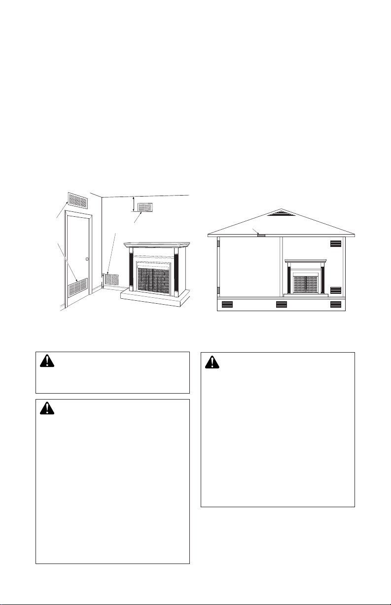
AIR FOR COMBUSTION AND VENTILATION
Continued
VENTILATION AIR
Ventilation Air From Inside Building
This fresh air would come from an adjoining
unconfined space. When ventilating to an
adjoining unconned space, you must provide
two permanent openings: one within 12" of the
ceiling and one within 12" of the oor on the
wall connecting the two spaces (see options 1
and 2, Figure 4). You can also remove door into
adjoining room (see option 3, Figure 3). Follow
the National Fuel Gas Code, ANSI Z223.1/
NFPA 54, Air for Combustion and Ventilation for
required size of ventilation grills or ducts.
12"
Ventilation
Grills
Into Adjoining
Room,
Option 1
Or
Remove
Door into
Adjoining
Room,
Option
3
Figure 3 - Ventilation Air from Inside
Ventilation Grills
Into Adjoining Room,
12"
Building
Option 2
INSTALLATION
Ventilation Air From Outdoors
Provide extra fresh air by using ventilation
grills or ducts. You must provide two permanent openings: one within 12" of the ceiling
and one within 12" of the oor. Connect these
items directly to the outdoors or spaces open
to the outdoors. These spaces include attics
and crawl spaces. Follow the National Fuel
Gas Code, ANSI Z223.1/NFPA 54, Air for
Combustion and Ventilation for required size
of ventilation grills or ducts.
IMPORTANT: Do not provide openings for
inlet or outlet air into attic if attic has a thermo-
stat-controlled power vent. Heated air entering
the attic will activate the power vent.
Ventilated
Attic
Crawl Space
Ventilated
To Attic
To
Crawl
Space
Outlet
Air
Inlet
Air
Outlet
Air
Inlet Air
Figure 4 - Ventilation Air from Outdoors
WARNING: A qualied service person must install rebox.
Follow all local codes.
CAUTION: Log heaters
installed in this rebox create
warm air currents. These currents move heat to wall surfaces
WARNING: Never install the
rebox
• in a bedroom or bathroom*
• in a recreational vehicle
• where curtains, furniture, clothing or other ammable objects
are less than 36" from front or
42" from top of rebox. For
side clearances see Figure 5,
next to rebox. Installing rebox
next to vinyl or cloth wall coverings or operating rebox where
impurities (such as, but not
limited to, tobacco smoke, aromatic candles, cleaning uids,
oil or kerosene lamps, etc.) in
the air exist, may discolor walls
or cause odors.
page 10
• in high trafc areas
• in windy or drafty areas
* Unless the installed log set is
rated at 10,000 Btu/Hr or less.
126709-01A 9
www.SuperiorFireplaces.US.com
INSTALLATION
Continued
IMPORTANT: Vent-free gas log heaters add
moisture to the air. Although this is benecial,
installing rebox in rooms without enough
ventilation air may cause mildew to form from
too much moisture. See Air for Combustion
and Ventilation, page 7.
IMPORTANT: Make sure firebox is level.
If rebox is not level, log set will not work
properly.
Note: Your rebox is designed to be used in
zero clearance installations. Wall or framing
material can be placed against any exterior
surface on rear, sides, top or bottom of rebox,
except where standoff spacers are integrally
attached. If standoff spacers are attached to
rebox, these spacers can be placed directly
against wall or framing materials.
Use dimensions shown for rough openings
to create the easiest installation (see Built-In
Firebox Installation, page 11).
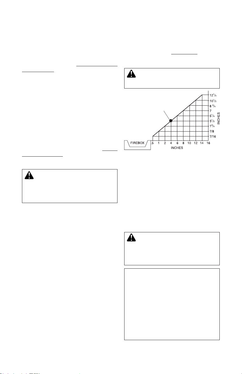
INSTALLATION CLEARANCES
WARNING: Maintain the
minimum clearances. If you can,
provide greater clearances from
oor, ceiling and adjoining wall.
Carefully follow these instructions. This will
ensure safe installation.
Minimum Wall and Ceiling Clearances (see
Figure 5)
A. Clearances from side of replace cabinet
to any combustible material and wall
should follow diagram in Figure 5.
Example: The face of a mantel, bookshelf,
etc. is made of combustible material and
protrudes 3 1/2" from wall. This combus-
tible material must be 4" from side of
replace cabinet (see Figure 5).
B. Clearances from top of rebox opening to
ceiling should not be less than 42".
C. When rebox is installed on carpeting or
other combustible material, other than
wood ooring, rebox should be installed
on a metal or wood panel extending full
width and depth of enclosure.
D. Clearances from bottom of rebox to oor
is 0".
These reboxes can be installed as freestanding units against a wall with approved, optional
cabinet mantels (see Accessories, page 15)
or as a built-in unit. Clearances are the same
for either installation method.
CAUTION: Do not install re-
box directly on carpet or vinyl.
Example
*
*Minimum 16" from Side Wall
Figure 5 - Minimum Clearance for
Combustible to Wall
Mantel Clearances for Built-In Installation
If placing custom mantel above built-in rebox,
you must meet minimum allowable clearance
between mantel shelf and top of rebox opening shown in Figure 6, page 11. These are
minimum allowable mantel clearances for a
safe installation. Use larger clearances wher-
ever possible to minimize heating of objects
and materials placed on mantel.
CAUTION: Do not allow
vent-free gas log heater to
touch or extend beyond replace screen.
NOTICE: Surface temperatures
of adjacent walls and mantels
become hot during operation.
Walls and mantels above rebox
may become hot to the touch.
If installed properly, these temperatures meet the requirement
of the national product standard.
Follow all minimum clearances
shown in this manual.
www.SuperiorFireplaces.US.com
126709-01A10

INSTALLATION
Supplied
Firebox
Hood
Must Be
Used at
All Times
Wire-mesh
Screen
Firebox
Noncombustible
Material May
Project Off
this Surface
above the
Firebox Hood
Mantel Shelf
Note: Any portion of the
mantel shelf must NOT
extend beyond this profile.
12" 16" 20"
1
1
/
2
"
6
3
/
4
"
12"
Note: All vertical
measurements are from
top of fireplace opening
to bottom of mantel shelf.
Wall board or facing
material (above
firebox) may be of
combustible material,
including decorative
mantel ornaments or
other similar projections off of the facing
material.
Framing
Material
These minimum clearances replace any other recommended
clearances supplied with your ANSI Z21.11.2 approved gas logs.
Depth
(Minimum)
Width
(Inside to Inside)
Height
37"
45°
42
1
/2"
5
2"
74"
TOP VIEW
FOR 36"
MODELS
30"
45°
35
7
/8"
4
2
7
/
16
"
60"
TOP VIEW
FOR 32"
MODELS
TOP VIEW
Continued
NOTICE: If your installation does
not meet the minimum clearances
shown, you must do one of the
following:
• raise the mantel to an acceptable height
• remove the mantel
BUILT-IN FIREBOX INSTALLATION
Built-in installation of this rebox involves
installing rebox into a framed-in enclosure.
This makes the front of rebox ush with wall.
Optional brass trim accessories are available
(see Accessories, page 15). Brass trim will
extend past sides of rebox approximately
1/2". This will cover rough edges of wall opening. If installing a mantel above rebox, you
must follow clearances shown in Figure 6.
Follow these instructions to install rebox in
this manner.
1. Frame in rough opening. Firebox framing
should be constructed of 2 x 4 lumber
or heavier. Use dimensions in table and
rough opening layout in Figure 7a. Adjust
framing so that rebox is ush with nished wall surface. If installing in a corner,
use dimensions in Figures 7b, 7c and 7d
for rough opening.
2. Install gas piping to rebox location. See Installing Gas Line, page 12 and Connecting
to Gas Supply in log set owner’s manual.
3. Carefully set rebox in front of rough opening with back of rebox inside wall open-
ing. IMPORTANT: If installing a perimeter
trim kit, see instructions included with
trim accessory. You must install shoulder
screws from trim kit now.
Rough Opening Dimensions for
Built-in Installation
Model
Front Width
(Inside to Inside) Height
Depth
(Min.)
32" 35 7/8" 36 3/4" 16 1/4"
36" 42 1/2" 40 1/2" 20 3/4"
42" 49 5/8" 44 1/2" 22 5/8"
Figure 7a
Figure 6 - Minimum Mantel Clearances
126709-01A 11
for Built-In Installation
www.SuperiorFireplaces.US.com
Figure 7b
Figure 7c
FOR 42"
49
5
86"
MODELS
/8"
Figure 7d
45°
1"
43"
Figure 7 - Rough Opening for Installing
6
in Wall
INSTALLATION
Continued
4. Carefully insert rebox into rough opening.
5. Attach rebox to wall studs using nails
or wood screws through holes in nailing
ange (see Figure 8).
6. If using an optional perimeter trim kit,
install trim after nal nishing and/or painting of wall. See instructions included with
trim accessory for attaching trim.
7. Install and properly test gas log heater.
Follow installation instructions included
with vent-free gas log heater that is being
installed.
IMPORTANT: When nishing your rebox,
combustible materials such as wall board,
gypsum board, sheet rock, drywall, plywood,
etc. may be butted up next to sides and top of
rebox. Combustible materials should never
overlap rebox front facing.
Nails or Wood
Screws
Nailing
Flanges
Indoor Firebox
Nails or
Wood
Screws
WARNING: Do not allow any
combustible materials to overlap
rebox front facing.
IMPORTANT: Noncombustible materials such
as brick, tile, etc. may overlap front facing, but
should never cover any necessary openings
like louvered slots.
WARNING: Do not allow
noncombustible materials to
cover any necessary openings
like louvered slots.
WARNING: Use only noncombustible mortar or adhesives when overlapping the front
facing with noncombustible
facing material.
INSTALLING FIREBOX USING
OPTIONAL ACCESSORY MANTELS
WARNING: A qualied service person must install rebox.
Follow all local codes.
This rebox may be installed using a cabinet
mantel accessory against a wall in your home.
Firebox and cabinet mantel can be installed
directly on oor. A trim kit is included with
mantel accessories. Follow instructions with
mantel for installation.
Nailing
Flanges
Indoor/Outdoor Firebox
Figure 8 - Attaching Firebox to Wall Studs
www.SuperiorFireplaces.US.com
126709-01A12

INSTALLATION
Continued
WARNING: Do not allow noncombustible materials to cover
any necessary openings.
WARNING: Do not ll the
spaces around the rebox with
insulation or other materials.
WARNING: Framing may be
placed or rest against replace
spacer, however; framing must
never be notched.
WARNING: Do not alter, cut
or modify replace spacers.
INSTALLING GAS LINE
NOTICE: A qualied service person must connect heater to gas
supply. Follow all local codes.
IMPORTANT: See Connecting to Gas Supply
in your log set owner’s manual for details on
gas hookup.
You may run gas line from either side or back
of rebox (see Figure 9, page 13). Decide
which side you want to run gas line from.
Note: This is one option for installing shutoff
valve. Check local codes for equipment shutoff valve location requirements.
Locate recessed knockout in one rebrick
liner (see Figures 9 and 10). Firmly tap center
of knockout with a chisel until it is released.
Carefully chisel rough edges of hole you have
made to smooth edges. This hole will line up
with hole in outer casing.
CAUTION: Do not use excessive force to remove the knockout. Too much force may damage
the rebrick concrete insert.
Equipment
Shutoff
Valves (Install
One)
Knockout
Locations
(Knock Out
One Hole)
Figure 9 - Installing Gas Line and
Equipment Shutoff Valve (Model May
Firebrick Side Wall
Knockout
Figure 10 - Location of Knockout for
Gas Line
Hole
Vary From Illustration)
Remove
this Area
Chisel
Gas Line
Side
View
126709-01A 13
www.SuperiorFireplaces.US.com

INSTALLATION
Continued
OPTIONAL OUTSIDE AIR KIT
(MODEL AK4/AK4F)
Installation of outside air kit should be per-
formed during rough framing of replace due
to the nature of it's location. Outside combus-
tion air is accessed through a vented crawl
space (AK4F) or through a sidewall (AK4).
See Figure 11.
CAUTION: Combustion air
inlet ducts shall not terminate
in attic space.
Secure to Collars with Metal Tape, Screws
or Straps (Min. of 1/4" x 20" in size)
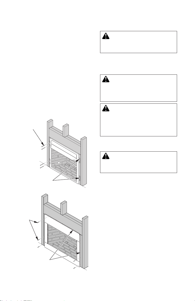
INSTALLING FIREPLACE HOOD
AND SCREEN
1. For Indoor models, attach hood and front
panel assembly by snapping panel assem-
bly into replace opening (see Figure 12).
Hood
Air Inlet
Location
Must Allow
For Bushes
or Snow
Air Inlet
Vented Crawl Space
(Check Local Codes
Before Installing in a
Vented Crawl Space)
Figure 11 - Outside Air Kit
2. For Indoor/outdoor models, loosen screws
along the replace top face. Remove two
screws along replace face side. Slide
hood underneath screws on top and
Hood
Eyebrow
Vent Hood
Required for
Wall Installation
Figure 12 - Hood Placement
(Model May Vary From Illustration)
tighten screws. Replace screws on side
of replace face side securing hood to the
face (see Figure 13).
3. Insert each screen rod through all rings
located at top of screen.
4. Insert rst rod into rear hole in left side of
rebox. Fasten rod to rear hole near center
of rebox using #10 x 3/8" Phillips screw
provided (see Figure 14).
5. Insert other rod into front hole on right
side of rebox and fasten using remaining
Phillips screw.
Top View of Rod Layout
Rear Hole
Front Hole
Rod
Ring
Identication
Label
Location
Remove/Replace
Side Screws
Figure 13 - Hood Placement
(Model May Vary From Illustration)
Loosen Top
Screws
www.SuperiorFireplaces.US.com
Screen
Figure 14 - Installing Fireplace Screen
(Model May Vary From Illustration)
Screw
126709-01A14

REPLACEMENT PARTS
Note: Use only original replacement parts.
This will protect your warranty coverage for
parts replaced under warranty.
Contact authorized dealers of this product. If
they can’t supply original replacement part(s),
call INNOVATIVE HEARTH PRODUCTS at
1-800-655-2008
TECHNICAL SERVICE
You may have further questions about installation, operation, or troubleshooting. If so,
contact INNOVATIVE HEARTH PRODUCTS
at 1-800-655-2008. When calling please have
your model and serial numbers of your heater
ready.
ACCESSORIES
NOTICE: All accessories may
not be available for all replace
models.
Purchase these accessories from your local
dealer. If they can not supply these accessories
call INNOVATIVE HEARTH PRODUCTS at
1-800-655-2008 for information. You can also
write to the address listed on the back page
of this manual.
HOODS
H36B - 36" Brushed Brass
H36P - 36" Platinum
H42B - 42" Brushed Brass
H42P - 42" Platinum
OUTSIDE AIR KIT
AK4 - Complete Kit w/ Collar, Hood and 3'
of Flex Tube
AK4X - Collar and Hood (accepts any
length of 4" ex tube)
AK4B - 50pc. Bulk Collar Only Kits
Optional kits provide additional air to reduce
build-up of condensation that occurs in today’s
tightly constructed homes.
MANTELS
32" Mantels
W32TU - 32" Wall Mantel, Unnished,
Traditional
W32TO - 32" Wall Mantel, Oak Stain,
Traditional
C32TU - 32" Corner Mantel, Unnished,
Traditional
When calling, have ready:
• your name
• your address
• model and serial numbers of your heater
• how heater was malfunctioning
• purchase date
Usually, we will ask you to return the part to
the factory.
You can also visit our web site at
www.IHP.US.com.
C32TO - 32" Corner Mantel, Oak Stain,
Traditional
W32CO - 32" Wall Mantel, Oak Stain, Classic
C32CO - 32" Corner Mantel, Oak Stain, Classic
W32DO - 32" Wall Mantel, Oak Stain, Dentil
W32GO - 32" Wall Mantel, Oak Stain,
Georgian
C32GO - 32" Corner Mantel, Oak Stain,
Georgian
36" Mantels
W36TU - 36" Wall Mantel, Unnished,
Traditional
W36TO - 36" Wall Mantel, Oak Stain,
Traditional
C36TU - 36" Corner Mantel, Unnished,
Traditional
C36TO - 36" Corner Mantel, Oak Stain,
Traditional
Note: No 42" mantels offered at this time.
PERIMETER TRIM
PT32 - 32" Black
PT32B - 32" Brushed Brass
PT32P - 32" Platinum
PT36 - 36" Black
PT36B - 36" Brushed Brass
PT36P - 36" Platinum
PT42 - 42" Black
PT42B - 42" Brushed Brass
PT42P - 42" Platinum
VENT FREE GAS LOGS
Please visit www.IHP.US.com for specic
models, sizing, specications and dealers
in your area.
126709-01A 15
www.SuperiorFireplaces.US.com
15
14
13
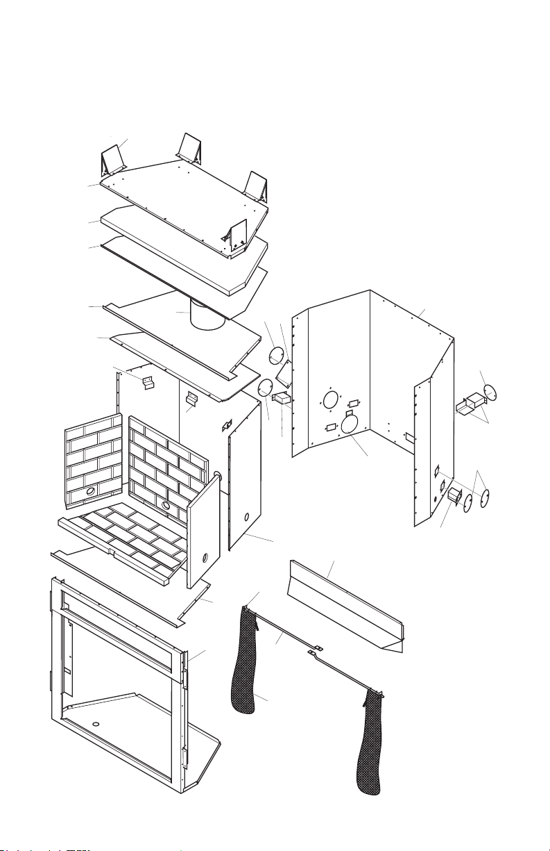
PARTS
32", 36", AND 42" MODELS
16
11
10
8
12
19
21
9
6
5
19
18
22
7
4
3
2
1
17
18
20
19
20/20a
www.SuperiorFireplaces.US.com
126709-01A16
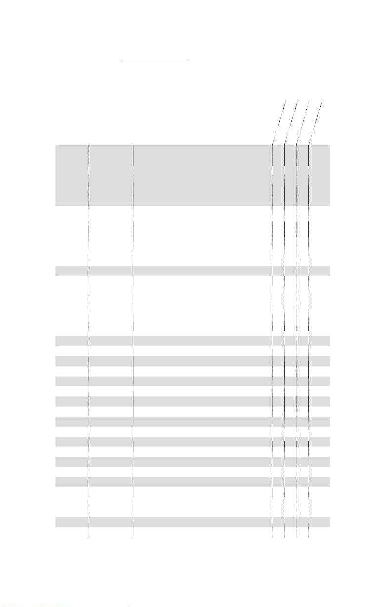
This list contains replaceable parts used in your rebox. When ordering parts, follow the
PARTS
instructions listed under Replacement Parts on page 14 of this manual.
KEY NO. PART NO. DESCRIPTION QTY.
32"
36"
42"
1 116207-01 Screen 36" • 2
116207-02 Screen 32" • 2
116207-03 Screen 42" • 2
116207-04 Screen 36" Stainless 2
116207-05 Screen 32" Stainless 2
116207-06 Screen 42" Stainless 2
2 108700-01 Screen Rod 32" • 2
106691-01 Screen Rod 36" • 2
107839-01 Screen Rod 42" • 2
117568-04 Screen Rod 32" Stainless 2
117568-05 Screen Rod 36" Stainless 2
117568-06 Screen Rod 42" Stainless 2
3 11418 Push-On Nut • • • 2
4 116631-01 Hood Assembly Panel • 1
116631-02 Hood Assembly Panel • 1
116631-03 Hood Assembly Panel • 1
108414-05 Stainless Hood 32" 1
107944-05 Stainless Hood 36" 1
107979-05 Stainless Hood 42" 1
5 ** Face Weldment • • • 1
6 ** Firebox Bottom • • • 1
7 ** Firebox Surround • • • 1
8 116531-01 Refractory Retainer • • • 2
9 116532-01 Rear Refractory Retainer • • • 1
10 108413-01 Firebox Top Shield • • • 1
11 ** Firebox Top • • • 1
12 ** Starter Pipe Collar • • • 1
13 ** Insulation Pan • • • 1
14 ** Fireplace Top Insulation • • • 1
15 ** Fireplace Top • • • 1
16 20280 Top Spacer • • • 4
17 ** Fireplace Surround • • • 1
18 108654-01 Gas Conduit Left and Right Assembly • 2
19 21171 Gas Knock-Out Cover • • • 3-5
20 107128-01 Gas Conduit • • • 2
20a 21379 Gas Conduit • • 2
21380 Gas Conduit • • 2
21 20042 Cover Plate • • • 1
22 **
Side Damper Weldment
• • • 1
** Not a eld replaceable part.
126709-01A 17
www.SuperiorFireplaces.US.com

PARTS
32", 36", AND 42" MODELS
2
1
3
4
KEY
NO. PART NO. DESCRIPTION QTY.
1 108434-03 Left Refractory Stacked Red • 1
108434-04 Left Refractory Stacked White • 1
122810-02 Left Refractory Herringbone Red • 1
122810-01 Left Refractory Herringbone White • 1
2 108430-03 Rear Refractory Stacked Red • 1
108430-04 Rear Refractory Stacked White • 1
122808-02 Rear Refractory Herringbone Red • 1
122808-01 Rear Refractory Herringbone White • 1
3 108432-03 Right Refractory Stacked Red • 1
108432-04 Right Refractory Stacked White • 1
122809-02 Right Refractory Herringbone Red • 1
122809-01 Right Refractory Herringbone White • 1
4 126065-02 Bottom Refractory Red • • 1
126065-01 Bottom Refractory White • • 1
www.SuperiorFireplaces.US.com
VRT4032RS
VRT4032WS
VRT4032RH
VTFB32H
126709-01A18

This list contains replaceable parts used in your rebox. When ordering parts, follow the
PARTS
instructions listed under Replacement Parts on page 14 of this manual.
KEY
NO. PART NO. DESCRIPTION QTY.
VRT4036RS
VRT4036WS
VRT4036RH
VRT4036WH
1 106658-04 Left Refractory Stacked Red • 1
106658-05 Left Refractory Stacked White • 1
122814-02 Left Refractory Herringbone Red • 1
122814-01 Left Refractory Herringbone White • 1
2 106660-04 Rear Refractory Stacked Red • 1
106660-05 Rear Refractory Stacked White • 1
122812-02 Rear Refractory Herringbone Red • 1
122812-01 Rear Refractory Herringbone White • 1
3 106659-04 Right Refractory Stacked Red • 1
106659-05 Right Refractory Stacked White • 1
122813-02 Right Refractory Herringbone Red • 1
122813-01 Right Refractory Herringbone White • 1
4 126066-02 Bottom Refractory Red • • 1
126066-01 Bottom Refractory White • • 1
KEY
NO. PART NO. DESCRIPTION QTY.
VRT4042RS
VRT4042WH
VRT4042RH
VRT4042WH
1 107812-04 Left Refractory Stacked Red • 1
107812-05 Left Refractory Stacked White • 1
122818-02 Left Refractory Herringbone Red • 1
122818-01 Left Refractory Herringbone White • 1
2 107816-04 Rear Refractory Stacked Red • 1
107816-05 Rear Refractory Stacked White • 1
122816-02 Rear Refractory Herringbone Red • 1
122816-01 Rear Refractory Herringbone White • 1
3 107814-04 Right Refractory Stacked Red • 1
107814-05 Right Refractory Stacked White • 1
122817-02 Right Refractory Herringbone Red • 1
122817-01 Right Refractory Herringbone White • 1
4 126067-02 Bottom Refractory Red • • 1
126067-01 Bottom Refractory White • • 1
126709-01A 19
www.SuperiorFireplaces.US.com

Innovative Hearth Products
Superior™ Brand Gas Fireplaces, Stoves and Inserts
20 Year Limited Warranty
THE WARRANTY
Innovative Hearth Products ("IHP") 20 Year Limited Warranty warrants your Superior™ Brand gas fireplace, Stove or Insert ("Product") to be free from defects in materials
and workmanship at the time of manufacture. The Product body and firebox carry the 20 Year Limited Warranty. Ceramic glass carries the 20 Year Limited Warranty against
thermal breakage only. After installation, if covered components manufactured by IHP are found to be defective in materials or workmanship during the 20 Year Limited
Warranty period and while the Product remains at the site of the original installation, IHP will, at its option, repair or replace the covered components. If repair or replacement
is not commercially practical, IHP will, at its option, refund the purchase price or wholesale price of the IHP product, whichever is applicable. IHP will also pay IHP prevailing labor rates, as determined in its sole discretion, incurred in repairing or replacing such components for up to five years. THERE ARE EXCLUSIONS AND LIMITATIONS
to this 20 Year Limited Warranty as described herein.
COVERAGE COMMENCEMENT DATE
Warranty coverage begins on the date of installation. In the case of new home construction, warranty coverage begins on the date of first occupancy of the dwelling or six
months after the sale of the Product by an independent IHP dealer/distributor, whichever occurs earlier. The warranty shall commence no later than 24 months following
the date of product shipment from IHP, regardless of the installation or occupancy date.
EXCLUSIONS AND LIMITATIONS
This 20 Year Limited Warranty applies only if the Product is installed in the United States or Canada and only if operated and maintained in accordance with the printed
instructions accompanying the Product and in compliance with all applicable installation and building codes and good trade practices.
This warranty is non-transferable and extends to the original owner only. The Product must be purchased through a listed supplier of IHP and proof of purchase must be
provided. The Product body and firebox carry the 20 Year Limited Warranty from the date of installation. Vent components, trim components and paint are excluded from
this 20 Year Limited Warranty. The following do not carry the 20 Year Limited Warranty but are warranted as follows:
Burner – Repair or replacement for one year from the date of installation
Gas components – Repair or replacement for one year from the date of installation
Gaskets – Repair or replacement for one year from the date of installation
Logs – Replacement for one year from the date of installation against thermal breakage only
Optional blowers & remote controls – Repair or replacement for one year from the date of installation
Optional glass doors – Repair or replacement for 90 days from the date of installation
Tempered glass - Replacement for one year from the date of installation
Labor coverage – Prevailing IHP labor rates apply for the warranty period of the component
Parts not otherwise listed carry a 90 day warranty from the date of installation.
Whenever practicable, IHP will provide replacement parts, if available, for a period of 10 years from the last date of manufacture of the Product.
IHP will not be responsible for: (a) damages caused by normal wear and tear, accident, riot, fire, flood or acts of God; (b) damages caused by abuse, negligence, misuse, or
unauthorized alteration or repair of the Product affecting its stability or performance (The Product must be subjected to normal use. The Product is designed to burn either
natural or propane gas only. Burning conventional fuels such as wood, coal or any other solid fuel will cause damage to the Product, will produce excessive temperatures
and could result in a fire hazard.); (c) damages caused by failing to provide proper maintenance and service in accordance with the instructions provided with the Product;
(d) damages, repairs or inefficiency resulting from faulty installation or application of the Product.
IHP is not responsible for inadequate fireplace system draft caused by air conditioning and heating systems, mechanical ventilation systems, or general construction conditions which may generate negative pressure in the room in which the appliance is installed. Additionally IHP assumes no responsibility for drafting conditions caused by
venting configurations, adjoining trees or buildings, adverse wind conditions or unusual environmental factors and conditions that affect the operation of the unit.
This 20 Year Limited Warranty covers only parts and labor as provided herein. In no case shall IHP be responsible for materials, components or construction, which are not
manufactured or supplied by IHP or for the labor necessary to install, repair or remove such materials, components or construction. Additional utility bills incurred due to
any malfunction or defect in equipment are not covered by this warranty. All replacement or repair components will be shipped F.O.B. from the nearest stocking IHP factory.
LIMITATION ON LIABILITY
It is expressly agreed and understood that IHP’s sole obligation and the purchaser’s exclusive remedy under this warranty, under any other warranty, expressed or implied,
or in contract, tort or otherwise, shall be limited to replacement, repair, or refund, as specified herein.
In no event shall IHP be liable for any incidental or consequential damages caused by defects in the Product, whether such damage occurs or is discovered before or
after repair or replacement, and whether such damage is caused by IHP’s negligence. IHP has not made and does not make any representation or warranty of fitness for a
particular use or purpose, and there is no implied condition of fitness for a particular use or purpose.
IHP makes no expressed warranties except as stated in this 20 Year Limited Warranty. The duration of any implied warranty is limited to the duration of this expressed warranty.
No one is authorized to change this 20 Year Limited Warranty or to create for IHP any other obligation or liability in connection with the Product. Some states and provinces
do not allow the exclusion or limitation of incidental or consequential damages, so the above limitations or exclusions may not apply to you. The provisions of this 20 Year
Limited Warranty are in addition to and not a modification of or subtraction from any statutory warranties and other rights and remedies provided by law.
INVESTIGATION OF CLAIMS AGAINST WARRANTY
IHP reserves the right to investigate any and all claims against this 20 Year Limited Warranty and to decide, in its sole discretion, upon the method of settlement.
To receive the benefits and advantages described in this 20 Year Limited Warranty, the appliance must be installed and repaired by a licensed contractor approved by IHP.
Contact IHP at the address provided herein to obtain a listing of approved dealers/distributors. IHP shall in no event be responsible for any warranty work done by a
contractor that is not approved without first obtaining IHP's prior written consent.
HOW TO REGISTER A CLAIM AGAINST WARRANTY
In order for any claim under this warranty to be valid, you must contact the IHP dealer/distributor from which you purchased the product. If you cannot locate the dealer/
distributor, then you must notify IHP in writing. IHP must be notified of the claimed defect in writing within 90 days of the date of failure. Notices should be directed to the
IHP Warranty Department at 1508 Elm Hill Pike, Suite 108; Nashville, TN 37210 or visit our website at WWW.SUPERIORFIREPLACES.US.COM.
Printed in U.S.A. © 2013 Innovative Hearth Products LLC
P/N 900223-00, Rev. NC 12/2013
Innovative Hearth Products
1508 Elm Hill Pike, Suite 108 • Nashville, TN 37210

KEEP THIS WARRANTY
Model (
located on product or identication tag
Serial No. (
located on product or identication tag
Date Purchased __________________________
Keep receipt for warranty verication.
WARRANTY
) _____________________________
) __________________________
126709-01A 21
www.SuperiorFireplaces.US.com

P126709-01
1508 Elm Hill Pike, Suite 108
Nashville, TN 37210
1-800-655-2008
www.IHP.US.com
126709-01
Rev. A
02/14
 Loading...