

Superior Electric SLO-SYN Micro Series, SLO-SYN 3180-PI10, SLO-SYN 3180-PI, SLO-SYN 3180 Series, SLO-SYN 3180-PI125 Instructions Manual

The Only Factory Authorized Repair Center for Superior Electric
Motor Systems Inc.
460 Milford Parkway
Milford, OH . 45150
www.motorsystems.com
513-576-1725
Stepper Drive & Motor Repair
PRICE:
$25.00
ecticut
060110-7488
1987
The Superlor Eleclr~c
Company
Artisan Technology Group - Quality Instrumentation ... Guaranteed | (888) 88-SOURCE | www.artisantg.com
The following are the minimum steps necessary for the Packaged
become operational.
Y
RESULT IN DAMAGE TO THE UNIT.
I.
DRIVE
Connect 120 volts ac, 50160 hertz to the AC input terminal strip.
The terminal labeled "H" is hot, "C" is common and
Check to see that the motor used is compatible with the drive. A
list of compatible motors is given in Section 3.3 of this manual.
Set the correct current level for the motor being used per the
instructions in Section 3.8 of this manual.
Wire the motor per Section 2.2, "Motor Connections" in this
manual.
Caution:
necting or disconnecting the motor connector or leads.
always disconnect the ac power to the unit when con-
FAILURE TO PERFORM THESE
"G"
is ground,
Be certain
the "PWR ON" LED is OFF before unplugging the motorconnector, or the drive will be damaged.
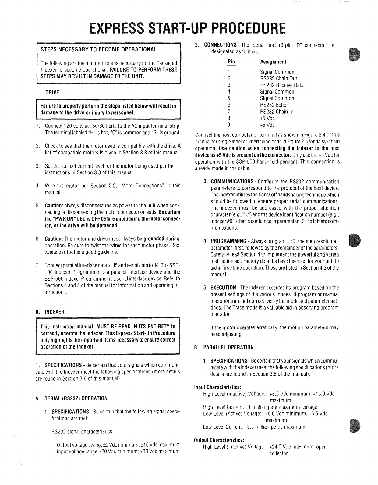
2. CONNECTIONS
designated as follows:
-
The serial port (9-pin "D" connector) is
Pin ssignment
Signal Common
RS232 Chain Out
RS232 Receive Data
Signal Common
Signal Common
6232 Echo
RS232 Chain In
t5 Vdc
t5 Vdc
Connect the host computer or terminal as shown in Figure 2.4 of this
manual for single indexer interfacing oras in Figure 2.5fordaisy-chain
operation,
device as
operation with the SSP-500 hand-held pendant. This connection is
already made in the cable.
Use caution when connecting the indexer to the host
+5
Vdc is present on the connector.
3. COMMUNICATIONS
parameters to correspond to the protocol of the host device.
The indexer utilizes the XonKoff handshaking technique which
should be followed to ensure proper serial communications.
The indexer must
character(e.g., "<")and the device identification number (e,g.,
indexer#Ol) that is contained in parameter L21 to initiate communications.
-
Configure the RS232 communication
be
addressed with the proper attention
Only use the t5 Vdc for
Caution:
operation. Be sure to twist the wires for each motor phase. Six
twists per foot is a good guideline.
Connect parallel interface data to J5 and serial datato J4. The SSP100 lndexer Programmer is a parallel interface device and the
SSP-500 lndexer Programmer is aserial interface device. Referto
Sections 4 and 5 of the manual for information and operating instructions.
The motor and drive must always be
grounded
during
This instruction manual MUST BE READ IN ITS ENTIRETY to
correctly operate the indexer. This Express Start-Up Procedure
only highlights the important items necessary to ensure correct
operation of the Indexer.
S
-
Be certain that your signals which communicate with the lndexer meet the following specifications (more details
are found in Section 3.6 of this manual).
.
SERIAL (RS232) OPERATIO
S
-
Be certain that the following signal speci
fications are met:
RS232 s~gnal characterrstics:
6
Output voltage swing:
lnput voltage range: -30 Vdc mlnimum: t30 Vdc maximum
Vdc minimum:
ltlO
Vdc maximum
4.
PROGRAMMING
parameter, first, followed by the remainder of the parameters.
Carefully read Section 4 to implement the powerful and varied
instruction set. Factory defaults have been set for your unit to
aid in first-time operation. These are listed in Section 4.3 of the
manual.
5.
EXECUTION
present settings of the various modes. If program or manual
operations are not correct, verify the mode and parameter settings. The Trace mode is a valuable aid in observing program
operation.
If the motor operates erratically, the motion parameters may
need adjusting.
-
Always program L70, the step resolution
-
The indexer executes its program based on the
PARALLEL OPERATION
1.
SPECIFICATIONS-
nicate with the indexer meetthe following specifications (more
details are found in Section 3.6 of the manual).
Be certain that yoursignals which commu-
lnput Characteristics:
High Level (inactive) Voltage: 4.5 Vdc minimum, t15.0 Vdc
maximum
1
High Level Current:
Low Level (Active) Voltage: tO.O Vdc minimum, t6.5 Vdc
Low Level Current: 3.5 milliamperes maximum
milliampere maximum leakage
maximum
Output Characteristics:
High Level (inactive) Voltage: t24.0 Vdc maximum, open
collector
Artisan Technology Group - Quality Instrumentation ... Guaranteed | (888) 88-SOURCE | www.artisantg.com

High Level Leakage Current: 250 microamperes maximum
leakage
Low Level Output: t0.4 Vdc at 16 milliamperes sink current
+0.7 Vdc at 40 milliam~eres sink current
2.
CONNECTIONS
pin "D" type connector. The pin assignments are as follows:
-The parallel signals are obtained via the 25-
I
General Comments
Pin Assignment
-
Signal Common 14
D7 Input* 15
D5 Input* 16
03 Input* 17
Dl Input* 18
Motion
Busy*? 19
Strobe 7* 20
5* 21
Strobe
Strobe 3" 22
Strobe 1
Output 2*t 24
All Windings Off Output't 25
Direction
*
Signals are active when low, inactive when high
t
Open collector output.
An example of a switch panel interface is displayed in Figure 5.2. The
diodes must be included
3.
COMMUNICATIONS
the timing requirements as shown in Figure 5.3. The LO7
parameter determines the timing of the strobes during the load
sequence.
4.
PROGRAMMING
be programmed first, after which the rest of the parameters
may be programmed. Carefully read Sections 4 and 5 of the
manual to learn how to implement the powerful and varied
instruction set. Factory default values have been set for your
unit to aid in first-time operation. These default values are
listed in Section 4.3 of the manual.
settings of the various modes.
tions are not correct, verify the mode and parameter settings.
If the motor operates erratically, adjust the motion parameters.
*
Outputet
for the indexer to operate successfully.
-
Proper parallel operation must observe
-
170. the step resolution parameter, must
-The indexer executes based on the present
Pin Assignment
-
Signal Common
05 Input*
D4 Input"
D2 lnput*
DO Input*
Not Used
Strobe
6*
Strobe 4*
Strobe 2*
23
If program or manual opera-
Strobe O*
I
Output
Pulse Output*t
*t
SLO-SYN Micro Serles drives use modern solld-state electronics such
as microprocessors to provide the features needed for- advanced
motion control applications. In some cases, these applications produce electromagnetic interference (EMI, or electrical "noise") that
may cause inappropriate operation of the microprocessor logic used
in the Micro Series product, or in any other computer-type equipment
in the user's system.
This guide is aimed toward helping users avoid such problems by
applying "good engineering practices" when designing their systems.
Following these guidelines will usually prevent
fering l~ith drive operation.
li
Noise Sources
What causes electrical norse? In general, any equrpment that causes
arcs or sparks or that switches voltage or current at high frequencies
can cause interference. In addition, ac utility lines are often "polluted"
with electrical noise from sources outside a user's control (such as
equipment in the factory next door).
The following are some of the more common causes of electrical
interference:
*
power from the utility ac line
*
relays. contactors and solenoids
*
hght dimmers
*
arc welders
*
motors and motor starters
*
induction heaters
*
radio controls or transmitters
sw~tch-mode power supplies
*
computer-based equipment
EM1 noise from inter-
FUSE AND MOTOR CONNECTOR PART NUMBERS
FOR
3180
SERIES UNITS
FUSE:
Littelfuse part number 225005
2AG. 5 amperes. 125 volts, fast acting
MOTOR CONNECTOR
Male connector body: AMP part number 206434-1
(5
required): AMP part number 66506-8
Pins
Cable clamp: AMP part number 206062-1
(mates with female motor connector on
drive)
Artisan Technology Group - Quality Instrumentation ... Guaranteed | (888) 88-SOURCE | www.artisantg.com
*
high frequency llghting equipment
*
dc servo and stepper motors and drives
Ill
Mounting Location
When selecting a mounting location ~t is preferable to keep the drive
away from obvious noise sources
possible locate the drive in rts own metal enclosure to shield it and its
wrmg from noise sources If this cannot be done keep the dr~ve at
least three feet from any nolse sources
such as those listed above If
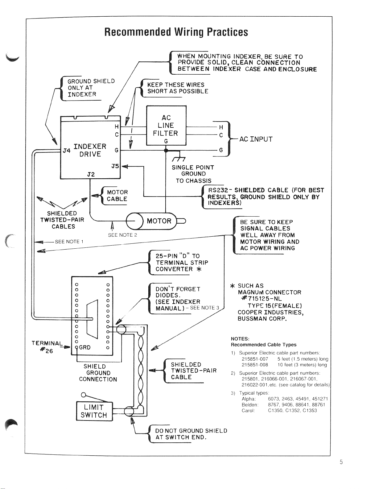
WHEN
MOUNTING
EXER,
BE
SURE TO
PROVIDE
SOLID,
AN CONNECTION
E
AND
ENCLOSU
P THESE WIRES
C
INPUT
I
I
J5
SINGLE POINT
I
GROUND
S
TWI
SEE
NOTE
1
SEE NOTE
2
-
BE SURE TO KEEP
OM
AND
AC POWER WIRING
Ud
CONNECTOR
TYPE
15(FEMALE)
OOPER INDUSTRIES,
USSMAN CORP.
NOTES:
Recommended Cable Types
1)
Superior Electr~c cable part numbers
215851 007
5
feet
(1 5
meters) Ions
21 5851 008
10
feet
(3
meters) long
2)
Superior Electric cable part numbers
215801 216066 001 216067 001
216022 001
etc
(see catalog for details
3)
Typ~cal types
Alpha
6073 2463 45491 451271
Belden
8767 9406 88641 88761
Carol
C1350 C1352 C1353
Artisan Technology Group - Quality Instrumentation ... Guaranteed | (888) 88-SOURCE | www.artisantg.com
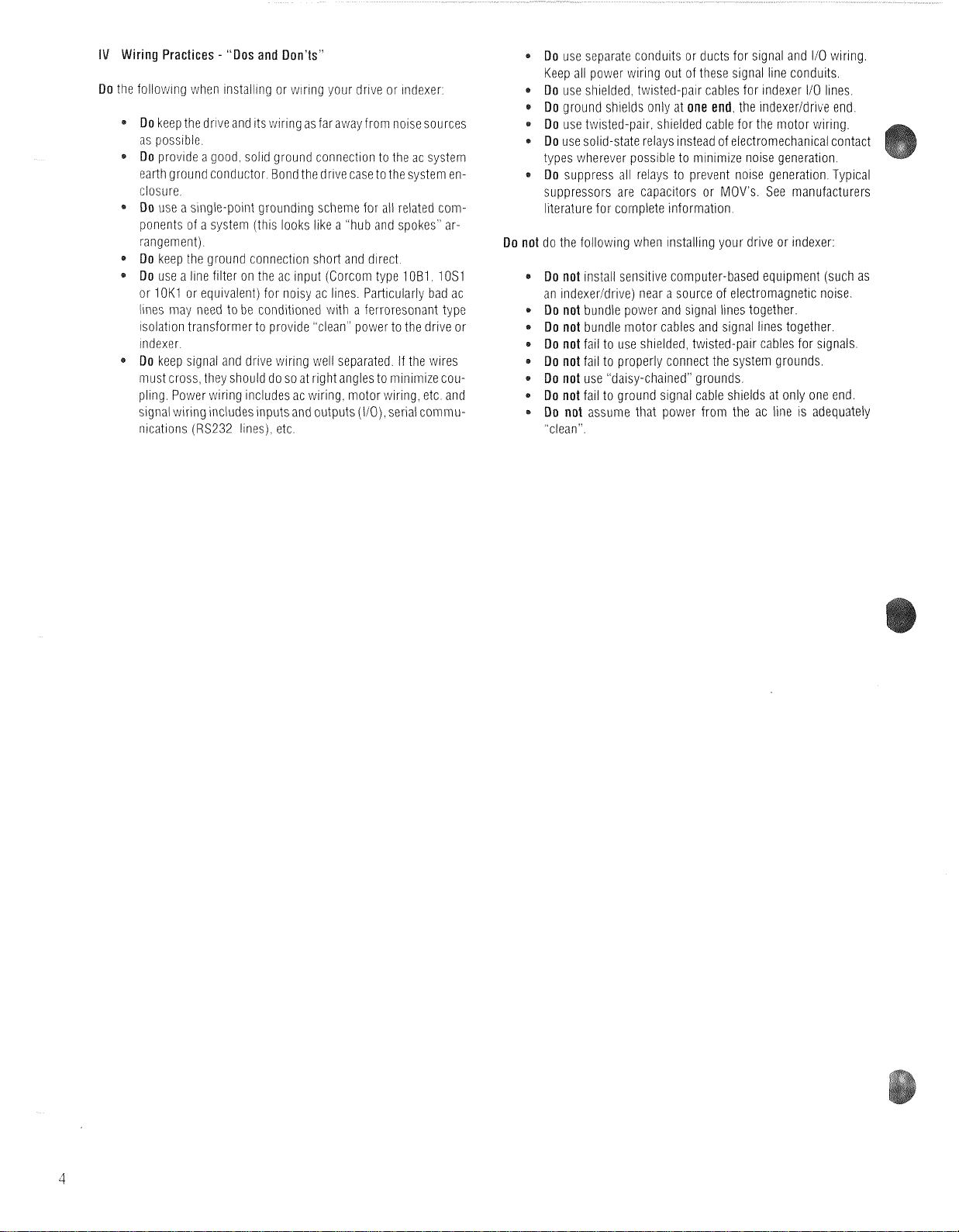
IV
Wiring Practices - "Dos and Don'ts"
Do
the folloviing when installing or wiring your drive or indexer
*
Do
keep the drive and its wiring as far away from noise sources
as possible
4
Do
provide a good solid ground connection to the ac system
earth ground conductor Bond thedrive case to the system enclosure
Do
use a srngle-point grounding scheme for ail related cornponents of a system (this looks like a hub and spokes arrangement)
Do
keep the ground connection short and direct
*
Do
use a line filter on the ac input (Corcorn type
or
lOK1
or eqwalent) for noisy ac lines Particularly bad ac
lines inay need to be conditioned with a ferroresonant type
isolation transformer to provide clean power to the drive or
indexer
Do
keep signal and drive wiring well separated If the wires
inust cross they should do so at right angles to minimize cou-
pling Power wiring includes ac wiring motor wiring etc and
srgnal wiring includes inputs and outputs (110) serial coinrnunicatrons
(RS232
lines) etc
10B1 10S1
*
Do
use separate conduits or ducts for signal and I10 wiring
Keep all power wiring out of these signal line conduits
*
Do
use shielded twisted-pair cables for indexer
*
Do
ground shields only at
*
Do
use twisted-pair shielded cable for the motor wiring
*
Do
use solid-state relays instead of electromechanical contact
types wherever possible to minimize noise generat~on
*
Do
suppress all relays to prevent noise generation Typical
suppressors are capacitors or MOVs See manufacturers
lrterature for complete
Do not
do the following when installing your drive or indexer:
Do not
install sensitive computer-based equipment (such as
an indexer1drive) near a source of
*
Do not
bundle power and signal lines together.
*
Do not
bundle motor cables and signal lines together.
*
Do not
fail to use shielded. twisted-pair cables for signals.
Do not
fail to properly connect the system grounds.
*
Do not
use "daisy-chained" grounds.
*
Do not
fail to ground signal cable shields at only one end.
*
Do not
assume that power from the ac line is adequately
"clean".
one end
information
the indexeridri~e end
electromagnetic
110
lmes
noise.
Artisan Technology Group - Quality Instrumentation ... Guaranteed | (888) 88-SOURCE | www.artisantg.com

V
AC
Line Filter
Use of an AC lhne filter on
Proper installation of the
31
80
and
61
80
Ser~es drlves
AC
Line Filter is essential
is recommended.
Asuitable filter is included with each unit supplied for sale in North America.
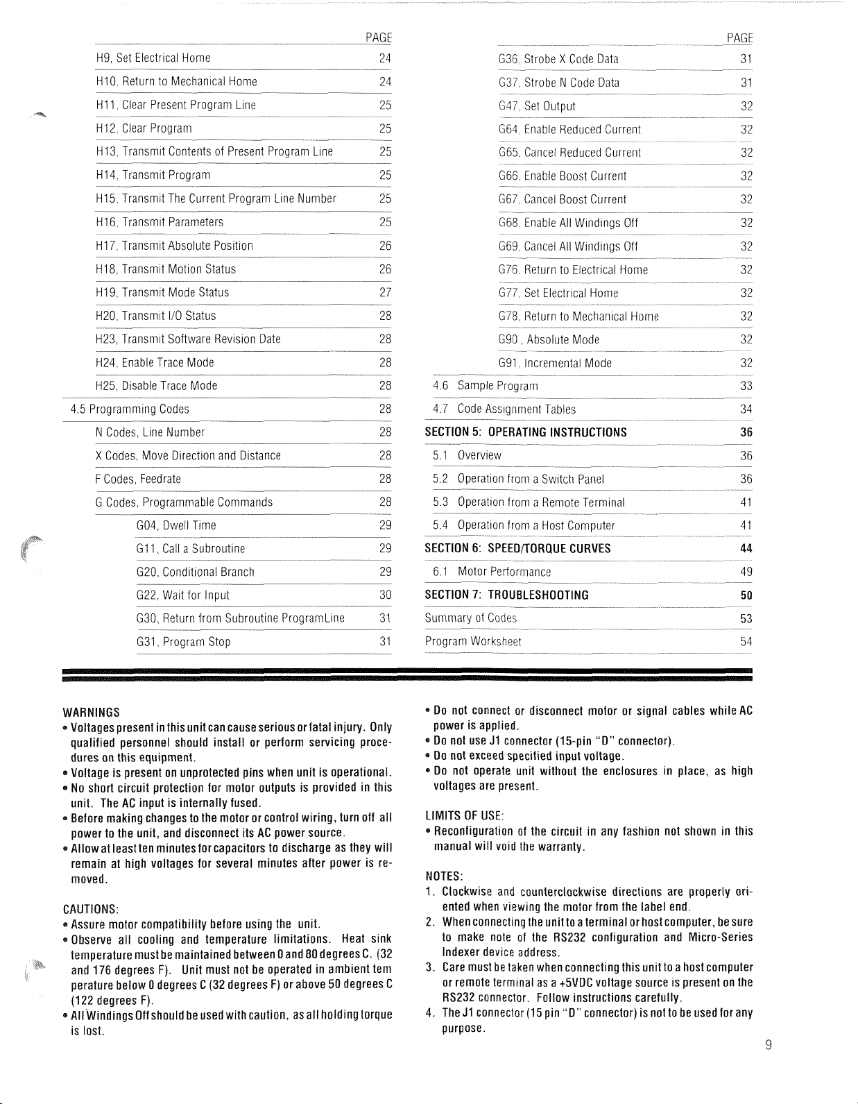
WARNING: Improper installation of the ac line filter may cause electrical shock, which could result in death, serious bodily
injury or property damage. To avoid electrical shock:
*The ac line filter must be installed by qualified personnel. Typical methods of locating and installing the line filter are
shown in Figures
1
and
2.
*The ac line filter must be firmly fastened near the Indexer. Failure to do so may result in damage to the filter and system.
*The installer must properly insulate and protect the ac connections to assure that the wires are not exposed. Exposed
wires could cause electrical shock, resutting in death, bodily injury or property damage.
If you have any questions regarding installation of the line filter, contact an electrician before installing the device.
For best performance:
*
The wlre between the Filter and the Drive should be less than two feet
(0.61
meter) long
Proper AC Line Filter Connections
VI
Troubleshooting Guide
Electrical interference problems are common with today's computer-based controls, and such problems are often difficult to diagnose and cure.
If such a problem occurs with your system. it is recommended that the following checks be made to locate the cause of the problem.
1.
Check the quality of the ac line voltage using an oscilloscope and a line monitor. such as the Superior Electric
age problems exist, use appropriate line conditioning, such as line filters or isolation transformers.
2.
Be certaln all of the previous Do's and Don'ts are followed for location, grounding, wring and relay suppression
3.
Double check the grounding connections to be sure they are good electrical connections and are as short and direct as possible.
4
Try
operating the drive wlth all suspected noise sources switched off If the drlve functions properly switch the noise sources on again
one at a time and try to Isolate whlch ones are causing the Interference problems When a noise source is located try rerouting wirlng
suppressing
relays or other measures to eliminate the problem
VMS
series. If linevolt-
Artisan Technology Group - Quality Instrumentation ... Guaranteed | (888) 88-SOURCE | www.artisantg.com
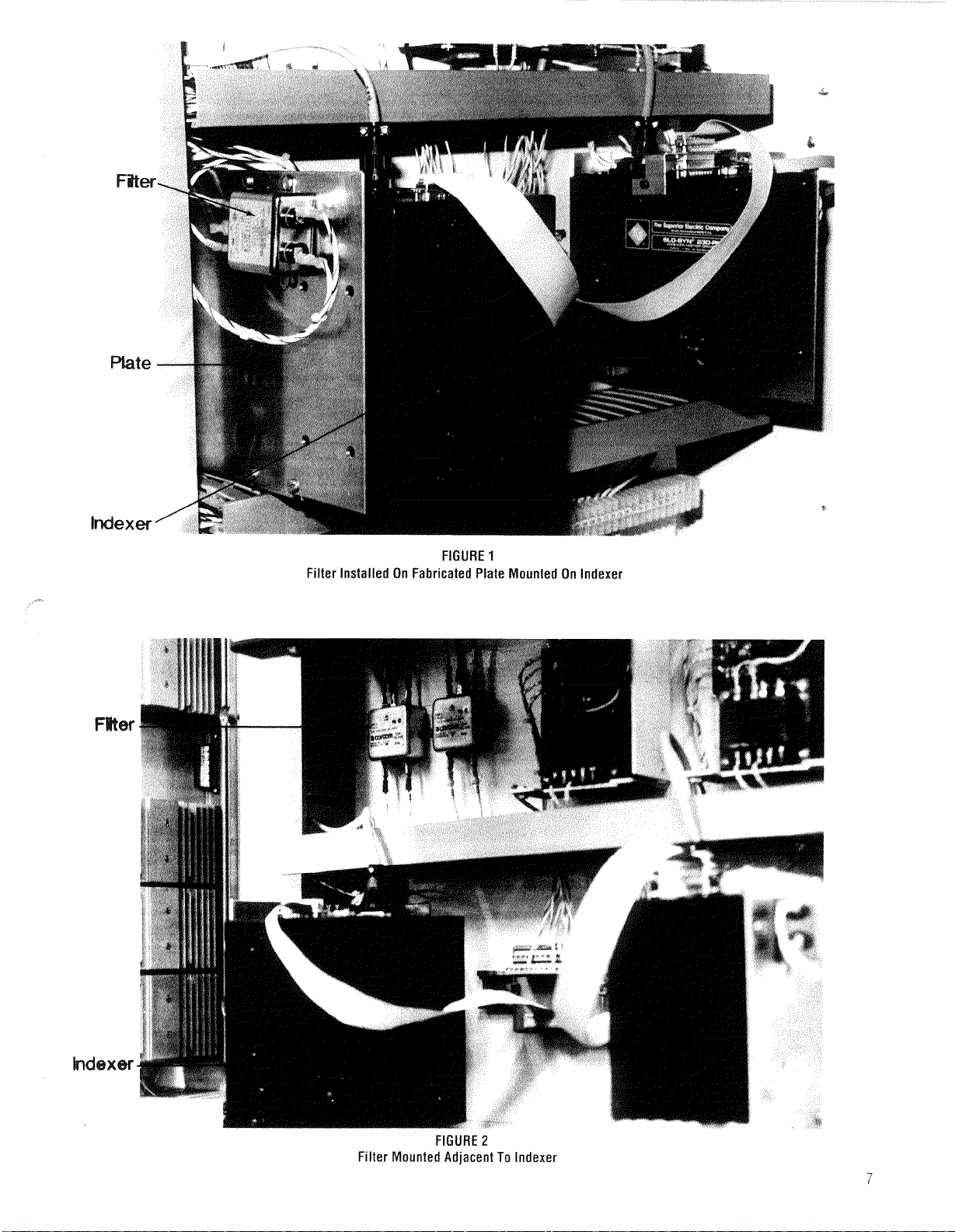
FIGURE
1
Filter installed On Fabricated Plate Mounted On Indexer
FIGURE
2
Filter Mounted Adjacent To Indexer
Artisan Technology Group - Quality Instrumentation ... Guaranteed | (888) 88-SOURCE | www.artisantg.com

PAGE
PRECAUTIONS
WARNINGS CAUTIONS. LIMITS OF USE. ETC 9
SECTION
1:
INTRODUCTION
1.1 Features Overview 10
1.2 Inspection parts list 10
1.3 Using this manual 10
1.3.1 Organization
9
10
4.1.3 Programming Chart
~
--
--
-.-
4.2 Immediate Commands
-
Clear 19
Freehold 19
Device Attention Character 19
Cycle Stop 19
Backspace and Delete 19
PAGE
1.3.2 Logic voltage and programming conventions 10 Delete Line 19
1.3.3 Indicator lights and AC fuse 10
SECTION
2:
MOUNTING, CONNECTIONS & PIN ASSIGNMENTS
11
4.3 L Codes: Indexer Parameters 19
L06, Program Execution Format
2.1 Mounting 11 107, Strobe Delay Time 20
2.2 Motor connections 11 L08, Mechanical Home Direction 20
2.3 Connection Diagrams 13 L09, Jog Speed 20
17
19
2.3.2 J2: Motor 13
2.3.3 J3: Power lnuut
2.3.4 34: Parallel
2.3.5 J5: Serial
2 4 Serial Communication Connection Diagrams
Single lndexer System
2 4
1
Multiple lndexer System
2 4 2
-
110
110
.
..
--
-
-.
--
-
--
-
-
2 5 Memory Protect Switch
SECTION
3:
SPECIFICATIONS
3 1 Drive Description
3 2 Drive Performance
--
-
3 3 Motor Compatibility
--
-
-
--
-
--
---
--
-
3 4 Drive Mechanical Specifications 15
3.5 Electrical Specifications 15
AC
35 1
3 5 2
-
3 6 Micro-Series-Indexer 110 Signal Interfaces
--
lnput
-
Output to Motor
-
--
--
3 6 1 Parallel I10
3 6 1 1 Parallel Output Characteristics 16
3 6 1 2
-
Parallel lnput Characteristics
--
--
3 6 2 Serial I10 16
3.7 Environmental Specifications 16
3
8 Current Settings
4
1 2 General Programming Comments 17
-
GUIDE
-
--
-
-
-
-
-
--
--
13
13
13
15
15
15
15
16
16
17
17
L1 2. Low Speed
L14, Home Speed 2
117, Offset Direction and Distance from
Mechanical Home 21
L18, Clockwise Software Travel Limit
119. Counterclockwise Software Travel Limit
L21. Assign Device Identification Number
L22, Baud Rate 22
L23, Character Length 22
L25, Parity 2 2
126, Indexer Ready Acknowledge 22
141, Auto Start Line Number
L44 Program Line Delay
--
L45 Limit Switch Enable 23
L48. Program Line Transfer Count
L49, Parameter Transfer Designation
-.
170, Translator Resolution 23
4 4 Codes Commands for Modes of Operation
--
-
-
-
- - - - -
-
HI Cycle Start
H2 Step Mode
H3 Jog Mode
H4. High Speed Mode 24
H5. Low Speed Mode 24
H6. Turn in CW Direction
Hi. turn in CCW Direction
H8 Return to Electrical Home 24
2 1
1
2 1
3
2
2 3
2 3
2 3
Artisan Technology Group - Quality Instrumentation ... Guaranteed | (888) 88-SOURCE | www.artisantg.com
H9, Set Electr~cal Home
-
--
--
HI0 Return to Mechanical Home 24
HI 1, Clear Present Program Line
HI 2. Clear Program 25
H13. Transmit Contents of Present Program L~ne
HI4 Transm~t Program
-.
--
-
H15, Transmit The Current Program Line Number
H16, Transmit Parameters 25
H17, Transmit Absolute Position 26
HI 8, Transmit Motion Status 2 6
HI 9, Transmit Mode Status 2 7
H20, Transmit I/O Status 28
H23, Transmit Software Revision Date 2 8
H24, Enable Trace Mode 28
H25, Disable Trace Mode 28
4 5 Programming Codes
--
N Codes Line Number 28
X
Codes, Move Direction and Distance
F
Codes, Feedrate
G Codes Programmable Commands
--
GO4 Dwell Time 29
-
GI 1 Call a Subrout~ne
--
G20 Conditional Branch
-
-
--
G22 Wait for Input 30
G30, Return from Subroutine ProgramLine 31
G31. Program Stop 3 1
PAGE
---
24
G36 Strobe X Code Data
31
G37 Strobe N Code Data 31
25
2 5
25
.-
25
G47 Set Output 3 2
G64 Enable Reduced Current
-
---
-
32
-
G65 Cancel Reduced Current 3 2
G66 Enable Boost Currerlt 32
G67 Cancel Boost Current 32
G68 Enable All Wmdings Off
--
-
32
G69 Cancel All Windings Off 32
G76 Return to Electrical Home
-
-
--
--
-
-
3 2
G77 Set Electrical Home 32
G78 Return to Mechanical Home
--
-
-
3 2
-
--
G90 Absolute Mode 32
G91, Incremental Mode 32
4.6 Sample Program 33
2 8
-
28
4.7 Code Assignment Tables 34
5:
SECTION
5
1 Overview
OPERATING INSTRUCTIONS 36
-
-
-
5 2 Operation from a Sw~tch Panel
28
--
5.3 Operation from a Remote Terminal 4 1
5.4 Operation from a Host Computer
6:
29
29
--
SECTION
6.1 Motor Performance 49
SECTION
Summary of Codes
-
SPEEORORQUE CURVES
7:
TROUBLESHOOTING
--
-
-
50
53
-
-
Program Worksheet 54
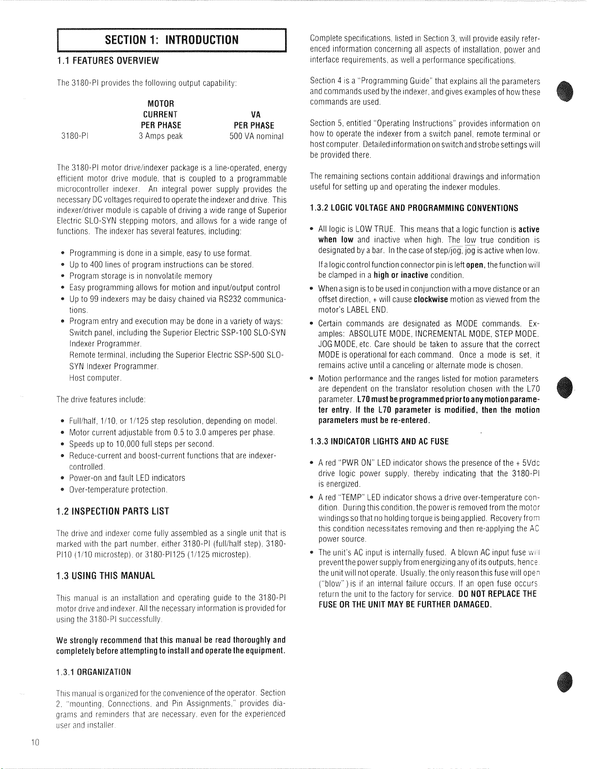
WARNINGS
*
Voltagespresent in this unit can causeserious or fatal injury. Only
qualified personnel should install or perform servicing procedures on this equipment.
*
Voltage is present on unprotected pins when unit is operational.
a
No short circuit protection for motor outputs is provided in this
unit. The AC input is internally fused.
*
Before making changes to the motor or control wiring, turn off all
power to the unit, and disconnect its AC power source.
*
Allow at least ten minutes for capacitors to discharge as they will
remain at high voltages for several minutes after power is removed.
*Assure motor compatibility before using the unit.
*Observe all cooling and temperature limitations. Heat sink
temperature must be maintained between Oand 80 degrees C. (32
and
176
degrees F). Unit must not be operated in ambient tern
perature below 0 degrees C (32 degrees F) or above 50 degrees
C
(122 degrees F).
*
All Windings Off should be used with caution, asall holding torque
is lost.
Artisan Technology Group - Quality Instrumentation ... Guaranteed | (888) 88-SOURCE | www.artisantg.com
*Do not connect or disconnect motor or signal cables while AC
power is applied.
*
00 not use J1 connector (15-pin "0" connector).
*
Do not exceed specified input voltage.
*Do not operate unit without the enclosures in place, as high
voltages are present.
LIMITS OF USE:
*
Reconfiguration of the circuit in any fashion not shown in this
manual will void the warranty.
NOTES:
1.
Clockwise and counterclockwise directions are properly oriented when viewing the motor from the label end.
2. When connecting the unit to a terminal or host computer, be sure
to make note of the
RS232 configuration and Micro-Series
Indexer device address.
3.
Care must be taken when connecting this unit to a host computer
or remote terminal as a +5VDC voltage source is present on the
RS232 connector. Follow instructions carefully.
4.
The
J1
connector (15 pin "D" connector) is not to be used for any
purpose.
9
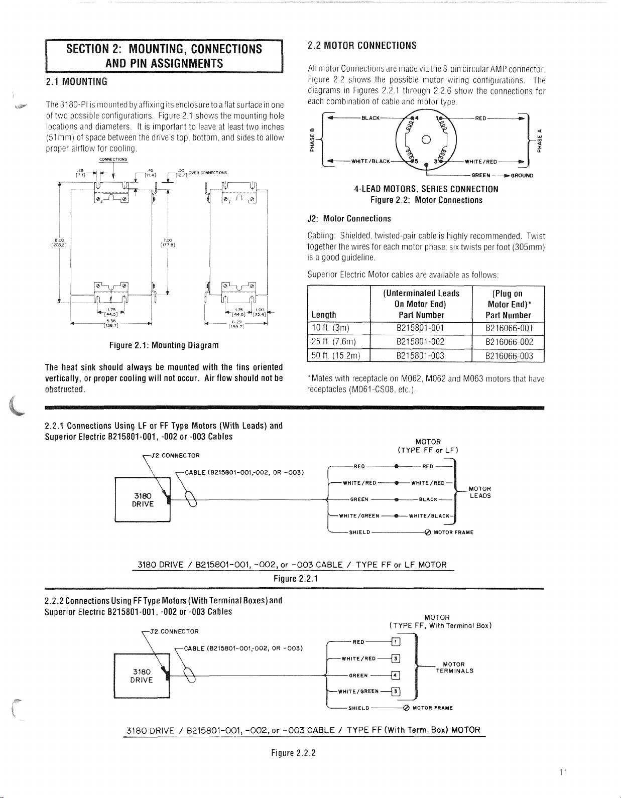
1.1
FEATURES OVERVIEW
Complete specifications listed in Section 3 will provide easily referenced information concerning all aspects of installation power and
interface requirements as well a performance specifications
The 3180-PI provides the following output capability:
MOTOR
CURRENT
VA
PER PHASE PER PHASE
3180-PI 3 Amps peak 500 VA nominal
The 3180-PI motor drivelindexer package is a line-operated, energy
efficient motor drive module, that is coupled to a programmable
m~crocontrolier indexer. An integral power supply provides the
necessary DC voltages required to operate the indexer and drive. This
indexeridriver module
Electric SLO-SYN stepping motors, and allows for a wide range of
functions, The indexer has several features, including:
Programming is done in a s~mple easy to use format
Up to 400 lines of program instructions can be stored
Program storage
Easy programming allows for motion and input/output control
99
Up to
tions
Program entry and execution may be done
Switch panel including the Superior Electric SSP-100 SLO-SYN
lndexer Programmer
Remote terminal including the Superlor Electric SSP-500 SLOSYN Indexer Programmer
Host computer
The drive features include.
Full/half 1/10 or 11125 step resolution depending on model
Motor current adjustable from 0
*
Speeds up to I0 000 full steps per second
*
Reduce-current and boost-current functions that are indexercontrolled
*
Power-on and fault LED indicators
*
Over-temperature protection
1.2
INSPECTION PARTS LIST
The drive and indexer come fully assembled as a single unit that is
inarked with the part number either 3180-PI (fullihalf step) 3180PI10 (1110 microstep) or 3180-PI125 (11125 microstep)
1.3
USING THIS MANUAL
This manual is an installation and operating guide to the 3180-PI
motor drive and indexer All the necessary information is provided for
using the 3180-Pi successfully
indexers may be daisy chained via RS232 communica-
is capable of driving a wide range of Superior
is in nonvolatile memory
in a variety of ways
5
to 3 0 amperes per phase
Section 4
and commands used by the indexer and gives examples of how these
commands are used
Section 5 entitled Operating Instructions provides information on
how to operate the indexer from a switch panel remote terminal or
host computer Detailed information on switch and strobesettings will
be provided there
The remaining sections contain additional drawings and information
useful for setting up and operating the indexer modules.
1.3.2
is a Programmrng Guide' that explains all the parameters
LOGIC VOLTAGE AND PROGRAMMING CONVENTIONS
All logic is LOW TRUE. This means that a logic function is
when low
designated by a bar. In the case of step/Eg,
If a logiccontrol function connectorpin is left
be clamped in a
When a sign is to be used in conjunction with a move distance or an
offset direction.
motor's LABEL END.
Certain commands are designated as MODE commands. Examples: ABSOLUTE MODE. INCREMENTAL MODE, STEP MODE.
JOG MODE, etc. Care should be taken to assure that the correct
MODE is operational for each command. Once a mode is set.
remains active until a canceling or alternate mode is chosen.
Motion performance and the ranges listed for motion parameters
are dependent on the translator resolution chosen with the L70
parameter.
and inactive when high. The low true condition is
jog
is active when low.
open,
the function will
high or inactive
+
will cause
condition.
clockwise
motion as viewed from the
L70 must be programmed priorto any motionparame-
active
it
ter entry. If the L70 parameter is modified, then the motion
parameters must be re-entered.
3.3
INDICATOR LIGHTS AND AC FUSE
A red "PWR ON" LED indicator shows the presence of the t 5Vdc
drive logic power supply. thereby indicating that the 3180-PI
is energized.
A red "TEMP" LEO indicator shows a drive over-temperature condition. During this condition. the power is removed from the motor
v~indings so that no holding torque is being applied. Recovery from
tlirs condition necessitates removing and then re-applying the
power source.
The unit s AC input is internally fused A blown AC input fuse
prevent the power supply from energizing any of its outputs hencs
the unit will not operate Usually theonly reason thlsfuse will ope?
(
blow ) is if an internal failure occurs If an open fuse occurs
return the unit to the factory for service
DO NOT REPLACE THE
AC
w
I
FUSE OR THE UNIT MAY BE FURTHER DAMAGED.
We strongly recommend that this manual be read thoroughly and
completely before attempting to install and operate the equipment.
1.3.1
ORGANIZATION
This inianuai is organized for the convenience of the operator Section
2
mounting Connections and Pin Assignments provides diagraiiis and reminders that are necessary even for the experienced
user and iiistaller
Artisan Technology Group - Quality Instrumentation ... Guaranteed | (888) 88-SOURCE | www.artisantg.com
The 31 80-PI is mounted by afflxing ~ts enclosure to aflat surface in one
of two possible
locations
configurations
and
diameters
Figure 2 1 shows the mounting hole
It is important to leave at least two inches
(51 rnm) of space between the drive stop bottom and sides to allow
2.2
MOTOR CONNECTIONS
All motor Connectioris are made vla the 8-pin circular AMP connector.
Figure 2.2 shows the possible rnotor wiring configurations. The
diagrarns in Figures 2.2.1 through 2.2.6 show the connections for
each comblnatiori of cable and motor type
BLACK
m
w
WHlTElBLACK
-QUEEN
-+
a
QRWND
4-LEA0 MOTORS, SERIES CONNECTION
Figure 2.2: Motor Connections
J2: Motor Connections
Figure 2.1: Mounting Diagram
The heat sink should always be mounted with the fins oriented
vertically, or proper cooling will not occur. Air flow should not be
2.2.1 Connections Using LF or FF Type Motors (With Leads) and
Superior Electric 8215801-001, -002 or -003 Cables
ZCONNECTOR
CABLE
(8215801-001;002,
OR
-003)
Cabling: Shielded. twisted-par cable
IS
highly recommended. Tw~st
together the wlres for each motor phase; six twists per foot (305mm)
IS
a good guideline.
Superior Electric Motor cables are available as follows.
Length
loft (3m)
(Unterminated Leads
On Motor End)
Part Number
821 5801 -001
(Plug on
Motor End)*
I
Part Number
1
B216066-001
*Mates wlth receptacle on M062, M062 and M063 motors that have
receptacles (M061 -CS08. etc
RED -RED
TE/RED bWHITE/RED-
GREEN -BLAC
WHITE/GREEN
SHIELD-@ MOTOR
--+---
)
MOTOR
(TYPE
WHITE/BLA
FF
or
LF)
FRAME
3180 DRIVE / 8215801-001,
-002,
Figure 2.2.1
2.2.2 Connections Using FFType Motors (With Terminal Boxes) and
Superior Electric B215801-001, -002 or -003 Cables
2
CONNECTOR
CABLE
3180
DRIVE
(8215801-001;002,
/
8215001-001, -002,or -003 CABLE / TYPE FF
OR
Figure 2.2.2
Artisan Technology Group - Quality Instrumentation ... Guaranteed | (888) 88-SOURCE | www.artisantg.com
or -003 CABLE / TYPE
-003)
WHITE/QREEN
SHIELD
~-0
FF
or LF MOTOR
(TYPE
(With
MOTOR
FF,
MOTOR
Term. Box) MOTOR
With
Terminal
MOTOR
TERMINALS
FRAME
Box)
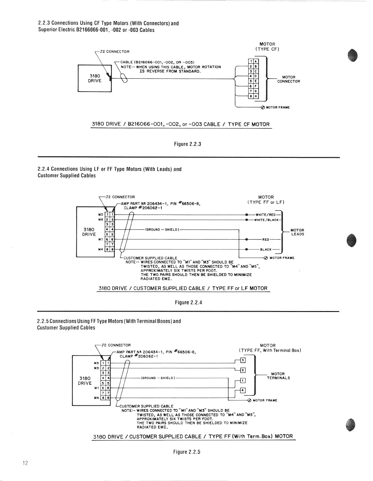
2.2.3 Connections Using CF Type Motors (With Connectors) and
Superior Electric 82166066-001, -002 or -003 Cables
CABLE (8216066-001,-002, OR -003)
OTOR
(TYPE CF)
-
MOTOR
CONNECTOR
3180 DRIVE / B216066-001, -002,
Figure 2.2.3
2.2.4 Connections Using LF or FF Type Motors (With Leads) and
Customer Supplied Cables
2 CONNECTOR
AMP PART Nr 206434-1, PIN "66506-8,
CLAMP *206062-1
(GROUND -SHIELD
L----------d
LCUSTOMER
NOTE:- WIRES CONNECTED TO "~1" AND "~3" SHOULD BE
SUPPLIED
TWISTED,
APPROXIMATELY SIX TWISTS PER FOOT.
THE TWO PAIRS SHOULD THEN BE SHIELDED TO MINIMIZE
RADIATED EMI.
CABLE
AS
WELL AS THOSE CONNECTEO TO "~4'' AND "M5",
3180 DRIVE / CUSTOMER SUPPLIED CABLE / TYPE FF
or
-003
CABLE / TYPE CF MOTOR
or
MOTOR
(TYPE FF
I-0
LF MOTOR
or
LF)
MOTOR
MOTOR
LEADS
FRAME
Figure 2.2.4
2.2.5 Connections Using FFType Motors (With Terminal Boxes) and
Customer Supplied Cables
NOTE:- WIRES CONNECTEO
TWISTED, AS WELL AS THOSE CONNECTED TO "M4"AND "M5",
APPROXIMATELY SIX TWISTS PER FOOT.
THE TWO PAIRS SHOULD THEN BE SHIELDED TO
RADIATED EMI.
3180
DRIVE / CUSTOMER SUPPLIED CABLE / TYPE FF(With Term.Box) MOTOR
TO
"Ml" AND "~3" SHOULD BE
Figure 2.2.5
Artisan Technology Group - Quality Instrumentation ... Guaranteed | (888) 88-SOURCE | www.artisantg.com
MINIMIZE
F,
With
Terminal
MOTOR FRAME
Box)

2.2.6 Connections Using CF Type Motors (With Connectors) and
Customer Supplied Cable
2
CONNECTOR
GROUND
-SHIELD)
LcusToMER SUPPLIED CABLE
NOTE:- WIRES CONNECTED TO "~1" AND "~3" SHOULD
TWISTED, AS WELL AS THOSE CONNECTED TO
APPROXIMATELY SIX TWISTS PER
THE TWO WlRS SHOULD THEN BE SHIELDED TO MINIMIZE
RADIATED EMI.
3180 DRIVE / CUSTOMER SUPPLIED CABLE / TYPE CF MOTOR
Figure 2.2.6
2.3
CONNECTION DIAGRAMS
2.3.1 J1: DO NOT USE (15-pin "0" type)
otor (see 3.5.2.1 for pin assignments)
53: Power Input (see 3.5.1.2 for terminal assignments)
2.3.3
2.3.4 J4: Parallel I10 Connections (25 pin. "0" type) (see 3.6.1 for
pin assignments)
2.3.5 55: Serial IlO(9-pin, "0"
type)(see3.6.2forpinassignments)
'7LoIoR
BE
"~4"
FOOT.
2.4
SERIAL COMMUNICATION CONNECTION DIAGRAMS
AND "M5",
rmw
2.4.1 Single lndexer System
In
a
slngie
~ndexer
systeln
~t
IS
init~ally transrnlttlng
Ing devlce
Flgure
HOST
RS
PORT
232
address
2
4
for
wlrlng Instructtons
3WlRE CONNtCIlON NO ECHO
ax
TI
VO
the
dev~ce
A
new
necessary
attentton
indexer
to actlvate
character
has
a
devlce
the
and
~ts
correspond-
address
INDEXER
9
lridexer
of
PIN CONNECTOR
1
by
See
/
I
Figure 2.3 3180-PI Connections
Artisan Technology Group - Quality Instrumentation ... Guaranteed | (888) 88-SOURCE | www.artisantg.com
SERIAL
CONNECTOR
110
J5
MEMORY PROTECT
SWITCH
PARALLEL
CONNECTOR
I10
J4
PWR. ON LED
TEMP. LED
AC INPUT
TERMINAL STRIP
J3
MOTOR CONNECTOR
J2
3
WlR€ CONNECTION WITH ECIi0
I
Figure 2.4 Single Indexer Connections
INDEXER
9
PIN CONNCCTOR
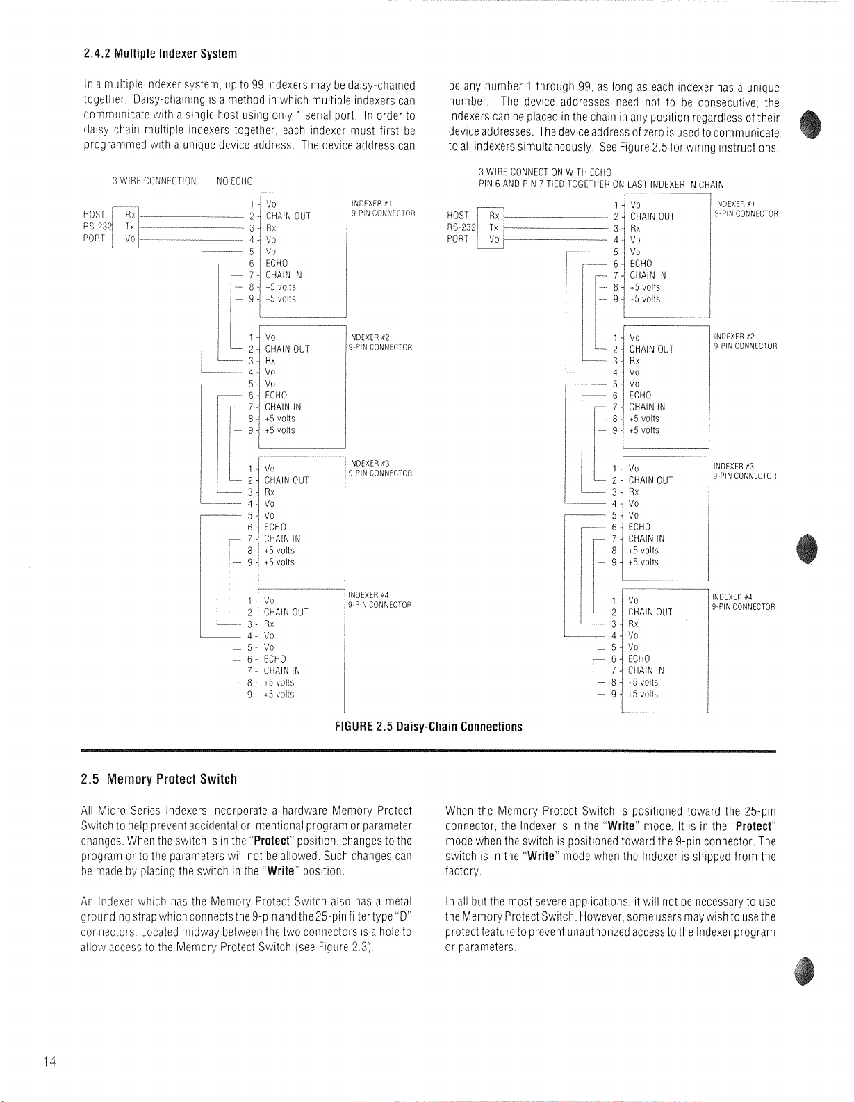
2.4.2
Multiple lndexer System
In a multiple indexer system. up to
99
indexers may be day-chained
together Dalsy-chaining
IS
a method in which muhple indexers can
communicate
with
a singie host uslng only 1 sera port. In order to
dalsy chaln multiple Indexers together, each indexer must first be
progran~med with a unlque device address. The device address can
3
WIRE
CONhECTlON
NO
ECHO
7-1
IPdEXER
#I
2.
CHAIN
OUT
I
9
PI4
CONNECTOR
3-
'Ivo
Rx
--
4
-I
vo
i
...
5:
vo
1
r---
6-1
ECHO
7
-
CHAIN
IN
1
1
cB!
15
volts
I
)
-
9
-1
15
volts
Ill
I
I
/
INDEXER
42
/
9
PIN
CONNECTOR
Ill
-
INDEXER
#3
9-PIN
CONNECTOR
1
INDEXER
#4
/
9-PIN
CONNECTOR
l
I
I
i
:
I
r--
--
3-
Rr
4-
vo
be any number
1
through 99, as long as each indexer has a unique
number. The device addresses need not to be consecutive; the
Indexers can be placed ~n the cnain in any position regardless of their
device addresses. The device address of zero is used to communicate
to all indexers simultaneously. See Figure
2.5
for wiring instructions.
-
5-
--
6
-
3
WIRE
CONNECTION
WITH
ECHO
PIN
6
AND
PIN
7
TIED TOGETHER
ON
LAST
INDEXER
IN
CHAIN
vo
ECHO
1
4
vo
INDEXER pl
HOST
I%--.-
---
2
'
CHAIN
OUT
9-PIN
CONNECTOR
RS-232,
Tx
t
3
1
Rx
--
7
4
CHAIN
IN
-
8
-/
15
volts
-
9
-i
45
volts
1
INDEXER
#3
9-PIN
CONNECTOR
FIGURE
2.5
Daisy-Chain Connections
t5
volts
15
volts
INDEXER
#4
9-PIN
CONNECTOR
emory Protect Switch
Ali Micro Series Indexers Incorporate a hardware Memory Protect When the Memory Protect Switch is positioned toward the 25-pin
Switch to help prevent accidental or intentional program or parameter connector, the lndexer is in the
"Write"
mode. It is in the
"Protect"
changes. When the swltch
IS
in the
"Protect"
position. changes to the mode when the switch
IS
positioned toward the 9-pin connector. The
program or to the parameters will not be allowed. Such changes can switch is in the
"Write"
mode when the lndexer is shipped from the
be made by
placing
the swltch in the
"Write"
position. factory.
An Indexer whlch has the Memory Protect Swltch also has a metal
in all but the most severe
applications
~t will not be necessary to use
grounding strap whch connects the 9-pin and the 25-pin filtertype D
'
the Memory Protect S~vitch However some users may wlsh to use the
connectors Located midway between the two connectors 1s a hole to
protect feature to prevent unauthorized access to the lndexer program
allov! access to the Memory Protect Switch (see Figure 2
3)
or parameters
Artisan Technology Group - Quality Instrumentation ... Guaranteed | (888) 88-SOURCE | www.artisantg.com
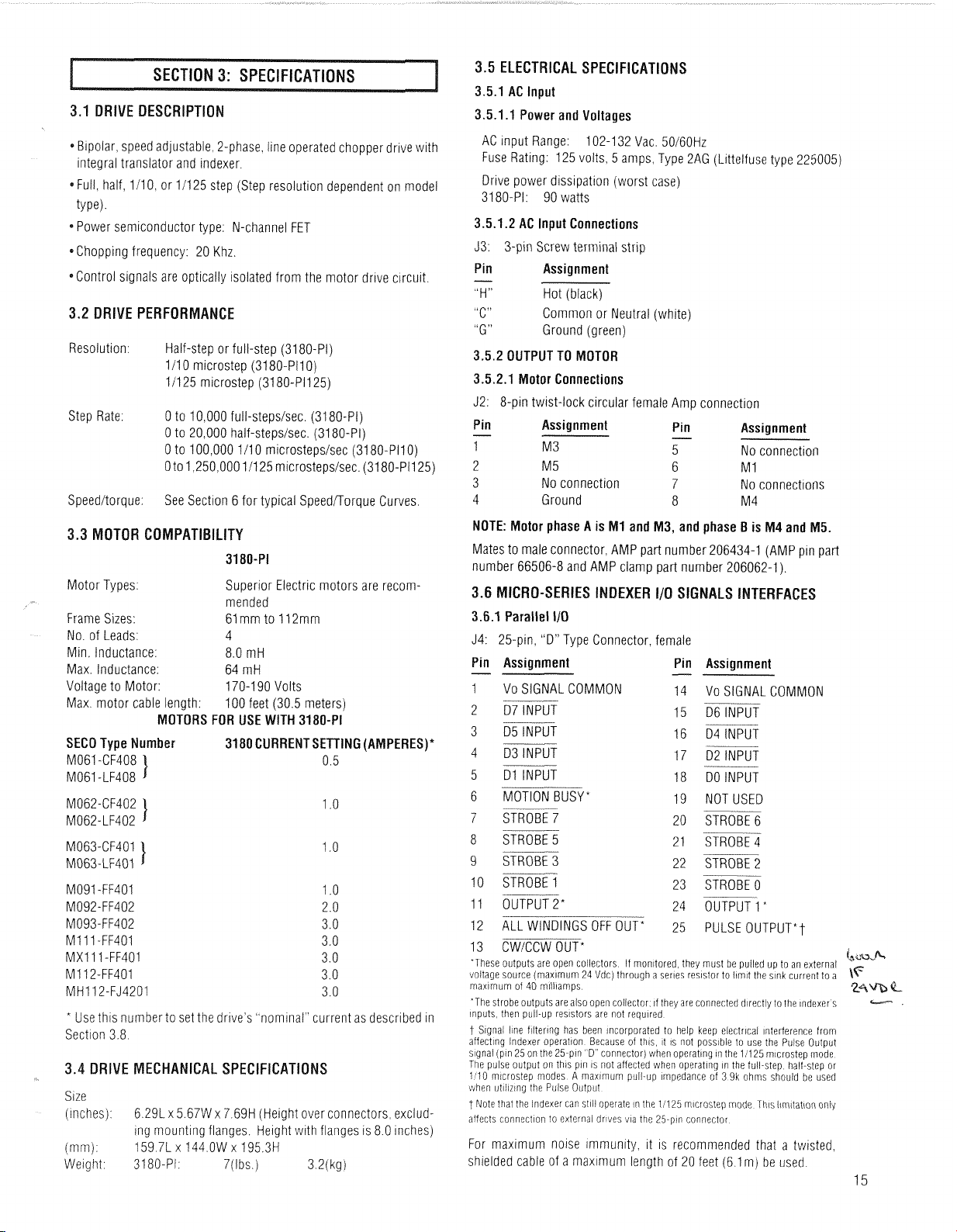
3.5
ELECTRICAL SPECIFICATIONS
3.5.1 AC lnput
3.1
DRIVE DESCRlPTlO
3.5.1.1 Power and Voltages
AC lnput Range:
102-1 32 Vac. 50160Hz
Fuse Rating: 125 volts, 5 amps, Type 2AG (Littelfuse type 225005)
*
Blpolar, speed adjustable, 2-phase. line operated chopper drive with
integral translator and indexer.
*Full, half, 111 0, or 111 25 step (Step resolution dependent on model
type).
Drive power dissipation (worst case)
3180-PI: 90 watts
3.5.1.2 AC lnput Connections
Power semiconductor type: N-channel FET
J3: 3-pin Screw terminal strip
*Chopping frequency: 20 Khz.
Pin
-
Assignment
"H" Hot (black)
"C"
Common or Neutral
"G" Ground (green)
*Control signals are optically isolated from the motor drive circuit.
3.2
DRIVE PERFORMANCE
(white)
Resolution: Half-step or full-step (3180-Pi)
1/10 microstep (3180-PI1 0)
11125 microstep (3180-P1125)
3.5.2 OUTPUT TO MOTOR
3.5.2.1 Motor Connections
J2: 8-pin twist-lock circular female Amp connection
Step Rate:
0 to 10,000 full-stepsisec. (3180-PI)
0 to 20,000 half-stepsisec. (3180-PI)
0 to 100,000 111 0 microstepsisec (3180-P110)
Oto 1,250,000 11125 microsteps1sec. (3180-PI1 25)
Pin
-
Assignment
-
Pin Assignment
1 M3 5
No connection
2 M 5
6 M 1
3 No connection 7 No
connectioils
4 Ground 8 M4 Speeditorque:
See Section 6 for typical SpeedDorque Curves
NOTE: Motor phase A is MI and M3, and phase B is M4 and M5.
Mates to male connector, AMP part number 206434-1 (AMP pin part
number 66506-8 and AMP clamp part number 206062-1).
Motor Types:
Superior Electric motors are recommended
Frame Sizes:
61 mm to 112mm
No. of Leads: 4
Min. Inductance: 8.0 mH
Max. Inductance: 64 mH
Voltage to Motor:
170-1 90 Volts
Max. motor cable length:
100 feet (30.5 meters)
MOTORS FOR USE WITH 3180-PI
SECO Type Number
3180 CURRENTSETTING (AMPERES)*
M061 -CF408
1
0.5
M061 -LF408
DEXER I10 SIGNALS
I
3.6.1 Parallel 110
J4: 25-pin, "D" Type Connector, female
Pin Assignment
-
1 Vo SIGNAL COMMON
2 07 INPUT
--
3 D5 INPUT
4 03 INPUT
Pin
Assignment
VO SIGNAL COMMON
--
D6 INPUT
-
--
D4 INPUT
--
D2 INPUT
--
-
DO INPUT
NOT USED
--
STROBE 6
STROBE 4
STROBE
2
--
STROBE 0
5 Dl INPUT
--
6 MOTION BUSY
*
--
7 STROBE
7
8 STROBE 5
9 STROBE 3
10 STROBE 1
M091 -FF401
M092-FF402
M093-FF402
MI 11 -FF401
MXl 1 1 -FF401
M1 12-FF401
MHI 12-FJ4201
--
11 OUTPUT2* 24 OUTPUT 1"
12 ALL
WINDINGS
OFF
OUT*
25
PULSE
OUTPUT*^
13 CWiCCW OUT*
in
m.,f+-
'These
outputs
are
open collectors
If
monitored
they
must
be
pulled
up
to
an
external
mltage
source
(maximum
24 Vdc)
through
a
series
resistor
to
limit
the
sink
current
to
a
\F
maximum
of
40
milliamps
'The
strobe
outputs
are
also
open
coliector,
if
they
are
conrlected
directly
to
lhe
indexers
----
inputs
then
pull-up
resistors
are
not
required
t
Signal
line
filtering
has
been
incorporated
to
help
keep
electrical
interference
from
affecting
Indexer
operation
Because
of
this,
it
is
not possibie
to
use
the
Pulse
Output
signai
(pin
25
on
the
25-pin ' D"
connector)
when
operating
in
the
1:125
microstep
mode
The
puise
output
on
this
pin
is
not
affected
when
operatinq
in
the
full-step
half-step
or
1/10
microstep
modes
A
maximum
piiil-up
impedance
of
3 9k
ohriis
should
be
used
vihen
utilizing
the
Puise
Outpu!
t
Note
that
the
Indexer
can
still
operate
in
the
11125
microstep
mode
This
lirnitation
only
affects
connection
to
external
dri'des
via
the
25-pin
connector
*
Use
this
number to set the drlve's
"nominal"
current as described in
Section 3 8
Size
(inches)
immi
Weight
MECHANICAL SPECIFICATIONS
6.291 x 5.67W x 7.69H (Height over connectors, excluding mounting flanges. Helght with flanges is 8.0 inches)
159.71 x 144.OW
x
195.3H
3180-PI: 7(lbs.) 3.2(kg)
For maximum noise
immunity,
it
IS
recommended that a twisted,
shielded cable of a maximum length of 20 feet (6.1 m) be used.
15
Artisan Technology Group - Quality Instrumentation ... Guaranteed | (888) 88-SOURCE | www.artisantg.com
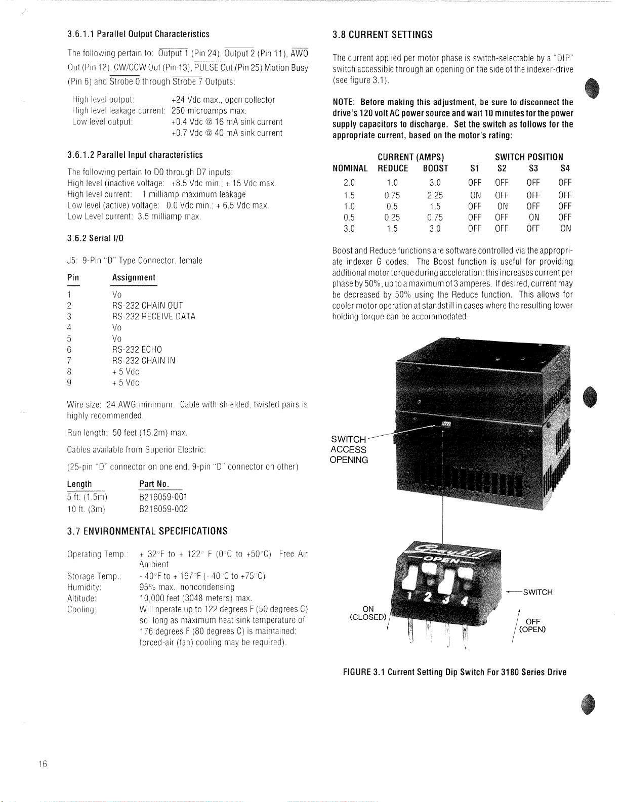
3.6.1.1 Parallel Output Characteristics
3.8
CURRENT SETTINGS
The follov~~ng pertain to Output 1 (Pin 24) Output 2 (Pin 11)
Out (Pin 12) CW CCW Out (Pin 13) %L~(PI~ 25) ~:tionX&
(Pin 6) and Strobe 0 through Strobe 7 Outputs
High level output.
124 Vdc max.. open collector
High level leakage current: 250 microamps max.
@
Low level output:
1-0.4 Vdc
t0.7 Vdc
16 mA sink current
@
40 mA sink current
3.6.1.2 Parallel Input characteristics
The following pertain to DO through 07 inputs:
t
High level (inact~ve voltage: t8.5 Vdc min.;
High level current:
1 milliamp maximum leakage
Low level (active) voltage: 0.0 Vdc mln.:
15 Vdc max
t
6.5 Vdc max.
[.ow Level current: 3.5 milliam~ max
3.6.2 Serial
110
35 9-Pin "D" Type Coriiiector female
Pin
1
2
3
4
5
6
7
8
9
Assignment
Vo
RS-232 CHAIN OUT
RS-232 RECEIVE DATA
Vo
Vo
RS-232 ECHO
RS-232 CHAIN IN
t
5 Vdc
t
5 Vdc
The current applied per motor phase is switch-selectable by a "DIP"
switch accessible through an opening on the s~de of the indexer-drive
(see figure 3.1).
NOTE: Before making this adjustment, be sure to disconnect the
drive's
120
volt AC power source and wait
10
minutes for the power
supply capacitors to discharge. Set the switch as follows for the
appropriate current, based on the motor's rating:
CURRENT (AMPS) SWITCH POSITION
NOMINAL REDUCE BOOST
2.0
1 .O
3.0 OFF OFF OFF OFF
1.5 0.75 2.25 ON OFF
1
.O
0.5 1.5 OFF ON OFF OFF
S1 S2 S3 S4
OFF OFF
0.5 0.25 0.75 OFF OFF ON OFF
3.0 1.5 3.0 OFF OFF OFF ON
Boost and Reduce functions are software controlled
G
ate Indexer
codes The Boost funct~on
via the appropri-
IS
useful for prov~d~ng
additional motortorque during acceleration this increases current per
phase by 50% up to a maximum of 3 amperes If desrred current may
be decreased by 50% using the Reduce functlon Thls allows for
cooler motor operation at standstill in cases where the
resulting
lower
holding torque can be accommodated
Wire size. 24 AWG minimum. Cable with shielded. tw~sted pairs is
higtily recommended.
Ruii length: 50 feet (15.2m) max
Cables available from Superlor Electric:
pin
(25
D
connector on one end 9-pin D connector on other)
Length Part No.
5 ft (1 51n) B216059-001
loft (3x1) 821 6059-002
VIRONMENTAL SPECIFICATIONS
t
Operating Temp
32 F to t 122
Anibient
-
Storage Temp
40 F to t 167 F
Humidity 95% max noncondensing
Altitude
Cooling
10 000 feet (3048 meters) max
Will operate up to 122 degrees
so long as maximuni heat sink temperature of
176 degrees
forced-air (fan) cooling may be required)
F (0 C to t50 C) Free Air
(-
40 C to t75 C)
F (50 degrees C)
F (80 degrees C) is maintained
SWITCH
-
ACCESS
OPENING
FIGURE 3.1 Current Setting Dip Switch For
3180
Series Drive
Artisan Technology Group - Quality Instrumentation ... Guaranteed | (888) 88-SOURCE | www.artisantg.com
This section contains the information necessary to set up,
enter, and edit programs and also to execute programs with the
Micro Series Indexer.
By carefully reading this section through in its entirety, the user
will fully understand the wide range of applications possible
with the Micro Series Indexer.
.1
OVERVIEW AN0 SET-U
EIA (Electronic Industries Association) Standard RS274-D is
the programming guide for numerically controlled machines.
Superior Electric has utilized this standard to form the basis for
the Micro Series Indexer's command structure. It was not
technically desirable to conform to the standard in complete
detail, but it proved beneficial in the program structure to
perform complex and varied operations with a simple format.
Using straightforward programming formats, the Micro Series
lndexer enables the user to program and execute in either
parallel (switch panel) or serial (remote terminal or host
computer) communication modes.
In general, all parameters and commands can be broadly
grouped into four categories, which correspond to these code
groupings:
1.
L
Codes
3.
N,
G,
X and F Codes
2.
H
Codes
4. Immediate Codes
1.
"L Codes" (discussed in Section 4.3) are used to set
parameters for each indexer. These commands are not considered part of an indexer program, that is, they are made prior to
any motion programming and do not have program line
num bers.
It is important to remember that the L codes are used exclu-
sively to set the initial parameters of a particular indexer and
should not be thought of as part of the program option for the
indexer.
Codes" (Section 4.4) are used to set indexer modes,
control manual and program execution and to transmit parameters and indexer status via the serial communications port.
H codes are not part of the programming commands for the
indexer. There are no program line numbers associated with
the
"H"
codes and they are not considered to be part of the
programming function.
and F
Codes" (Section 4.5) are the programming
commands for the indexer. Up to 400 lines of program instruc-
tions can be stored as a unique motion control program.
Each program is in a fixed format, and is composed of a line
number, a "G" code, an
"Xu
code and an
"F"
field.
A line of program has this format:
N[nnn) G[nn] X[snnnnnnnn] F[nnnnnnn]
A space is used to separate the codes.
Not all codes need be programmed for each program line.
The G,
X
and F codes may be programmed in any order.
:
The brackets,
[I,
are used in this manual for clarity
h,
and are not to be used when entering data
or
variables
4. lmmediate Codes (Section 4.2) are executed immediately
upon receipt and are not stored as part of the program. All
commands are highlighted in bold face for easy reference.
4.1.2 General Programming Comments
T PROGRAMMING NOTES**
1.
The indexer contains a 40 character serial buffer
to
accept all data and programming entries.
If
a COMMAND
TERMINATOR (CARRIAGE RETURN and/or LINE FEED) is
not received by the 40th character, the buffer contents art:
dumped and that 40 character strina is lost.
Upon receipt of a CR and/or LF, an XOFF (ASCII Code 19)
character is transmitted to the host; no further data trans-
mission from the host should occur. However, any characters transmitted subsequent to XOFF will be stored in
the buffer until the buffer capacity is reached. if the
capacity is exceeded, the buffer contents are dumped.
The receipt of a COMMAND TERMINATOR character will
cause the commands in the buffer to be executed sequentially. That is, the first command that was entered will be
the first command executed. The COMMAND DELIMITER
for a series of commands is a space. Once all the com-
mands in the buffer have been executed, the indexer will
send an XON (ASCII Code 17) character and will be ready
to receive further data.
2. Whether the indexer is being operated from a switch
panel, remote terminal or host computer, the first task that
faces an operator, after all circuit connections have been
made, is that of setting
"L:
codes", the parameters of each
indexer.
3.
In the following descriptions, it is important to note the
factory default values for each parameter as entry steps
can be eliminated. Upon receipt of a new indexer, the default
ilalues will have been entered for the parameters.
I.
Motor speeds and acceleration will depend on theTRANSLATOR RESOLUTION setting (L70 nnn). Set this parameter
first and then work in ascending numerical order starting
@ith the LO6 parameter.
NOTE: If the L70value is changed, the valuesfor L09, L11,
L12, L14 and the "F" field values must be reentered.
5.
Entry of invalid data for a parameter or program field will
-esult in the previous data being left intact.
3.
If the number of characters entered exceeds the number
~f required characters, the data is truncated to the maxinum field length for the entry.
XoniXoff Protocol:
The Xoff character is transrnitted to the host when a CR or LF is
received The lndexer will process the information it has received and
v!iII transmit an Xon character when it is ready to accept more
information
from the host The lndexer should be polled to determine
when it is ready to accept more information If
L26
3
is selected the
lndexer will transmit an
=
if it is ready to accept more ~nformation
If an Xoff chardcter has been transmitted to the host and the command
received by the lndexer calls for motion or progrdm execution the
lndexer will send an Xon to the host This allo?.!s the host to send any
of the immediate commands such as
*
[Clear) S (Feed Hold) or
#
(Cycle Stop) The host shoiild not send normal commands until
the lndexer is ready to accept more information The lndexer will be
ready to accept more information when motion is stopped program
is stopped and all
previoiis commands have been executed
17
Artisan Technology Group - Quality Instrumentation ... Guaranteed | (888) 88-SOURCE | www.artisantg.com
 Loading...