

Page 1

Superior Broadcast LLC
Superior Broadcast
SBFM100-SS
User Manuals
Superior Broadcast LLC
18208 Preston Rd. Suite D9-297, Dallas, TX 75252. www.sbp-tv.com
Page 2

Superior Broadcast SBFM100SS Transmitter
Superior Broadcast where the Best Cost Less
Call us today. We want to talk to You
Superior Broadcast
18208 Preston Rd, Suite D9-297, Dallas, TX 75252
Tel: 972-473-2577 | Email: [email protected]
www.sbp-tv.com
All rights reserved.
Printed and bound in the U.S.A . No part of this manual may be reproduced, memorized or transmitted
in any form or by any means, electronic or mechanic, including photocopying, recording or by any
information storage and retrieval system, without written permission of the copyright owner.
Tel: 972-473-2577 | Email: [email protected]
18208 Preston Rd. Suite D9-297, Dallas, TX 75252. www.sbp-tv.com
SBFM100SS Transmitter User Manual
Superior Broadcast
Jimmie Joynt
Superior Broadcast
Page 3

Superior Boadcast SBFM100SS Transmitter
TEX30/50/100/150/300/502/702-LCD
ELETTRONICA
Table of Contents
1. Preliminary Instructions 1
2. Warranty 1
3. First Aid 2
3.1 Treatment of electrical shocks 2
3.2 Treatment of electrical Burns 2
4. General Description 3
4.1 Unpacking 3
4.2 Features 3
4.3 Frontal Panel Description 5
4.4 Rear Panel Description 6
4.5 Connectors Description 7
4.6 Technical Description 9
5. Quick guide for installation and use 10
5.1 Preparation 10
5.2 First power-on and setup 12
5.3 Operation 14
5.4 Management Firmware 16
5.5 Optional Function 22
6. Identication and Access to the Modules 24
6.1 Identication of the Modules 24
7. Working Principles 28
7.1 TEX30/50/00/50/300/502/702LCD Common Parts 28
7.2 TEX30LCD Different Parts 29
7.3 TEX50/100/50LCD Different Parts 30
7.4 TEX300LCD Different Parts 32
7.5 TEX502/702LCD Different Parts 33
Superior Broadcast
SBFM100SS Transmitter User Manual
Page 4

Superior Broadcast SBFM100SS Transmitter
This page was intentionally left blank
SBFM100SS Transmitter User Manual
Superior Broadcast
Page 5

Superior Boadcast SBFM100SS Transmitter
ATVST-CNV
IMPORTANT
The lightning ash with arrowhead, within a triangle, is intended to alert the user of the presence
of dangerous voltage that may constitute a risk of electric shock.
The exclamation point within an equilateral triangle is intended to alert the user to the
presence of important operating and maintenance (servicing) instructions in the literature
accompanying the equipment.
1. Preliminary Instructions
• General foreword The equipment in object is to considering for uses,
installation and maintenance from “trained” or “qualied” staff, they conscious
of the risks connected to operate on electronic and electrical circuits electrical.
The “trained” denition means staff with technical knowledge about the use of
the equipment and with responsibility regarding the own safety and the other
not qualied staff safety place under his directed surveillance in case of works
on the equipment. The “qualied” denition means staff with instruction and
experience about the use of the equipment and with responsibility regarding
the own safety and the other not qualied staff safety place under his directed
surveillance in case of works on the equipment.
WARNING: The machine can be equipped with an ON/OFF switch
which could not remove completely voltages inside the machine. It is
necessary to have disconnected the feeding cord, or to have switched
off the control panel, before to execute technical operations, making sure
himself that the safety connection to ground is connected. The technical
interventions that expect the equipment inspection with circuits under
voltage must be carry out from trained and qualied staff in presence of
a second trained person that it is ready to intervene removing voltage in
case of need.
Superior Broadcast doesn’t assume responsibility for injury or damage
resulting from improper procedures or practices by untrained/unqualied
personnel in the handling of this unit.
WARNING: The equipment is not water resistant and an inltration could
seriously compromise its correct operation. In order to prevent res or
electric shocks, do not expose the equipment to rain, inltrations or
humidity.
Please observe all local codes and re protection standards during installation
and use of this unit.
WARNING: The equipment has to its inside exposed parts to risk of electric
shock, always disconnect power before opening covers or removing any part
of this unit.
Fissures and holes are supplied for the ventilation in order to assure a reliable
efcacy of the product that for protect itself from excessive heating, these
ssures do not have to be obstructed or to be covered. The ssures doesn’t be
obstructed in no case. The product must not be incorporated in a rack, unless
it is supplied with a suitable ventilation or that the manufacturer’s instructions
are been followed.
WIRING: This device has a connection to ground on the power cord and
on the chassis. Check that they are correctly connected.
Operate with this device in a residential ambient can cause radio disturbs;
in this case, it can be demanded to the user to take adequate measures.
Specications and informations contained in this manual are furnished for
information only, and are subject to change at any time without notice, and
should not be construed as a commitment by Superior Broadcast.
The Superior Broadcast assumes no responsability or liability for any errors
or inaccuracies that may appear in this manual, including the products and
software described in it;and it reserves the right to modify the design and/
or the technical specications of the product and this manual without notice.
• Warning regarding the use designated and the use limitations of the
product.
This product is an transmitter radio indicated for the audio broadcasting
service in frequency modulation. It uses working frequencies that are not
harmonized in the states of designated user. The user of this product must
obtain from the Authority for spectrum management in the state of designated
user the appropriate authorization to use the radio spectrum, before putting
in exercise this equipment. The working frequency, the transmitter power, let
alone other specications of the transmission system are subject to limitation
and denited in the authorization obtained.
2. Warranty
Superior Broadcast guarantees absence of manufacturing defect and the
good operation for the products, within the provided terms and conditions.
Please read the terms carefully, because the purchase of the product or
acceptance of order conrmation, constitutes acceptance of the terms and
conditions. For the last legal terms and conditions, please visit our web site
www.sbp-tv.com) wich may also be changed, removed or updated for any
reason without prior notice. Warranty will be void in cases of opened products,
physical damage, misuse, modication, repair by unauthorised persons,
carelessness and using the product for other purpose than its intended use. In
case of defect, proceed like described in the following:
1. Contact the dealer or distributor where you purchased the unit.
Describe the problem and, so that a possible easy solution can be
detected.
Dealers and Distributors are supplied with all the information about problems
that may occur and usually they can repair the unit quicker than what the
manufacturer could do. Very often installing errors are discovered by dealers.
2. If your dealer cannot help you, contact Superior Broadcast and explain
the problem. If it is decided to return the unit to the factory, Superior
Broadcast will mail you a regular authorization with all the necessary
instructions to send back the goods;
WIRING: This equipment can irradiate radio frequency energyand if it’s
not installed following the instructions contained in the manual and local
regulations it could generate interferences in radio communications
Superior Broadcast
3. When you receive the authorization, you can return the unit. Pack it
carefully for the shipment, preferably using the original packing and seal
the package perfectly. The customer always assumes the risks of loss
(i.e.,
1
SBFM100SS Transmitter User Manual
Page 6

Superior Broadcast SBFM100SS Transmitter
Superior Broadcast. is never responsible for damage or loss), until the
package reaches R.V.R. premises. For this reason, we suggest you to insure
the goods for the whole value. Shipment must be effected C.I.F. (PREPAID)
to the address specied by Superior Broadcast’s service manager on the
authorization
DO NOT RETURN UNITS WITHOUT OUR
AUTHORIZATION AS THEY WILL BE REFUSED
4 Be sure to enclose a written technical report where mention all the
problems found and a copy of your original invoice establishing the starting
date of the warranty.
Replacement and warranty parts may be ordered from the following address.
Be sure to include the equipment model and serial number as well as part
description and part number.
Superior Broadcast
18208 Preston Rd, Suite D9-297
Dallas, TX 75252
Tel: 972-473-2577
3. First Aid
The personnel employed in the installation, use and maintenance of the
device, shall be familiar with theory and practice of rst aid.
3.1 Treatment of electrical shocks
3.1.1 If the victim is not responsive
Follow the A-B-C’s of basic life support.
• Place victim at on his backon a hard surface.
• Open airway: lift up neck, push forehead back
(Figure 1).
Figure 5
• In case of only one rescuer, 15 compressions alternated to two
breaths.
• If there are two rescuers, the rythm shall be of one brath each 5
compressions.
• Do not interrupt the rythm of compressions when the second
person is giving breath.
• Call for medical assistance as soon as possible.
3.1.2 If victim is responsive
• Keep them warm.
• Keep them as quiet as possible.
• Loosen their clothing (a reclining position is recommended).
• Call for medical help as soon as possible.
3.2 Treatment of electrical Burns
3.2.1 Extensive burned and broken skin
• Cover area with clean sheet or cloth.
• Do not break blisters, remove tissue, remove adhered particles of
clothing, or apply any salve or ointment.
• Treat victim for shock as required.
• Arrange transportation to a hospital as quickly as possible.
• If arms or legs are affected keep them elevated.
Figure 1
• clear out mouth if necessary and observe for breathing
• if not breathing, begin articial breathing (Figure 2): tilt head,
pinch nostrils, make airtight seal, four quick full breaths
Remember mouth to mouth resuscitation must be commenced as
soon as possible.
Figure 2
• Check carotid pulse (Figure 3); if pulse is absent, begin
articial circulation (Figure 4) depressing sternum (Figure 5).
If medical help will not be available within an hour and the victim is conscious
and not vomiting, give him a weak solution of salt and soda: 1 level teaspoonful
of salt and 1/2 level teaspoonful of baking soda to each quart of water (neither
hot or cold).
Allow victim to sip slowly about 4 ounces (half a glass) over a period of 15
minutes.
Discontinue uid if vomiting occurs.
DO NOT give alcohol.
3.2.2 Less severe burns
• Apply cool (not ice cold) compresses using the cleansed available
cloth article.
• Do not break blisters, remove tissue, remove adhered particles of
clothing, or apply salve or ointment.
• Apply clean dry dressing if necessary.
• Treat victim for shock as required.
• Arrange transportation to a hospital as quickly as possible.
• If arms or legs are affected keep them elevated.
Figure 3 Figure 4
SBFM100SS Transmitter User Manual
2
Superior Broadcast
Page 7

Superior Boadcast SBFM100SS Transmitter
TEX30/50/100/150/300/502/702LCD
ELETTRONICA
4. General Description
The TEX30/50/100/150/300/502/702LCD, manufactured by R.V.R. Elettronica
SpA, are exciters for Frequency Modulated audio broadcasting in a frequency
modulation able to transmit in the band between 87.5 and 108 MHz, in step of 10
KHz, with an RF output power adjustable up to a maximum of 30, 50, 100, 150,
300, 500 and 700 W respectively into a 50 Ohm standard load.
The TEX30/50/100/150/300/502/702LCD are designed to being contained into a
19” rack box of 2HE.
4.1 Unpacking
The package contains:
1 TEX30LCD, TEX50LCD, TEX100LCD, TEX150LCD, TE300LCD, TEX502LCD
or TEX702LCD
1 User Manual
1 Mains power cables
The following accessories are also available from Your R.V.R. Dealer:
• Accessories, spare parts and cables
4.2 Features
These exciters contain a low-pass lter that reduces the harmonic emission to
provided for by international standards (CCIR, FCC or ETSI) and can be connected
directly to the antenna.
Two major features of TEX30/50/100/150/300/502/702LCD are compact design
and user-friendliness. Design is based on a modular concept: the different functions
are performed by modules that, for the most part, are connected through male and
facilitates maintenance and module replacement.
The RF power section of the TEX30LCD features a MOSFET module delivering
up to 30W output power, the TEX50/100/150LCD features a
delivering up to 150W output power, the TEX300LCD features a MOSFET module
delivering up to 300W output power, whereas the TEX502LCD features two
MOSFET modules with up to 350 W output power each; the TEX702LCD features
a MOSFET module delivering up to 800W output power
MOSFET module
Operating frequency stability is ensured by a temperature-compensated reference
oscillator and is maintained by a PLL (Phase Locked Loop) system. The exciters
will go into frequency lock within 30 seconds after power-on.
The TEX30/50/100/150/300/502/702LCD can operate throughout the frequency
bank with no need for calibration or set-up.
Superior Broadcast
3
SBFM100SS Transmitter User Manual
Page 8

Superior Broadcast SBFM100SS Transmitter
TEX30/50/100/150/300/502/702LCD
ELETTRONICA
An LCD on the front panel and a push-button board provide for user interfacing
with the microprocessor control system, which offers the following features:
• Output power setup.
• Operating frequency setup.
• Power output enable/disable.
• Power Good feature (User-selectable output power alarm threshold).
• Measurement and display of transmitter operating parameters.
• Communication with external devices such as programming or telemetry
systems via RS232 serial interface or I
Four LEDs on the front panel provide the following status indications: ON, LOCK,
FOLDBACK and RF MUTE.
The exciters have an input for the external 24 Vcc supply. This auxiliary supply
source, that can be realized by the user with the help of rescue batteries, is
automatically used in case of AC voltage absence.
2
C.
The exciter management rmware is based on a menu system. User has four
navigation buttons available to browse submenus:
ESC , , , ed ENTER.
The rear panel features the mains input connectors, as well as audio input
connectors and RF output connector, telemetry connector, protection fuses and
two inputs for signals modulated onto subcarriers by suitable external coders, such
as RDS (Radio Data System) signals commonly used in Europe.
SBFM100SS Transmitter User Manual
4
Superior Broadcast
Page 9
TEX30/50/100/150/300/502/702LCD
ELETTRONICA
4.3 Frontal Panel Description
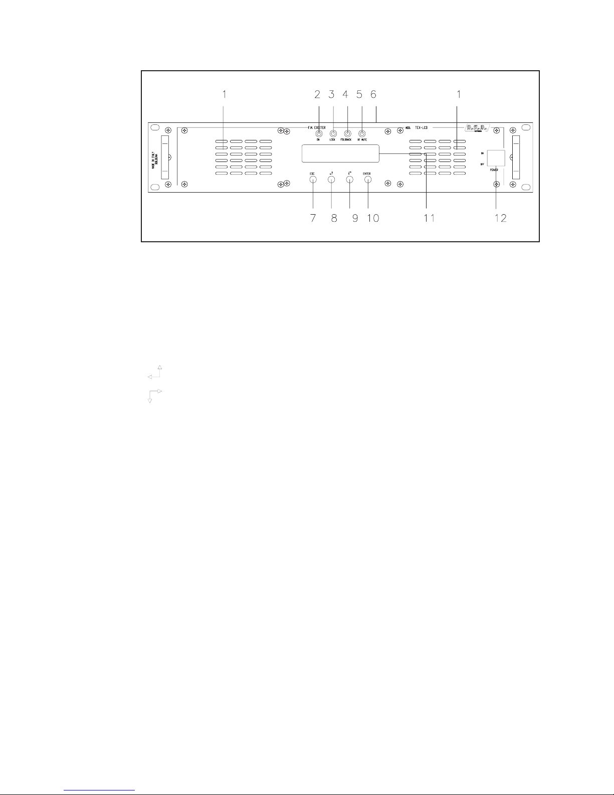
[1] AIR FLOW Air ow for the forced ventilation.
[2] ON Green LED, lit when the exciter is working.
[3] LOCK Green led, lit when the PLL is locked on the working frequency.
[4] FOLDBACK Yellow LED, lit when the foldback function is operating (automatic
reduction of the delivered RF power).
[5] R.F. MUTE Yellow LED, lit when the exciter’s power output is inhibited by an
external interlock command.
[6] CONTRAST Display contrast adjusting trimmer (on the top of the equipment).
[7] ESC Push button to exit from a menu.
[8] Push button to move in the menu system and to modify the
parameters.
[9] Push button to move in the menu system and to modify the
parameters.
[10] ENTER Push button to conrm a parameter and to enter in a menu.
[11] DISPLAY Liquid crystals display.
[12] POWER ON/OFF switch.
Superior Boadcast SBFM100SS Transmitter
Superior Broadcast
5
SBFM100SS Transmitter User Manual
Page 10
Superior Broadcast SBFM100SS Transmitter
TEX30/50/100/150/300/502/702LCD
ELETTRONICA
4.4 Rear Panel Description
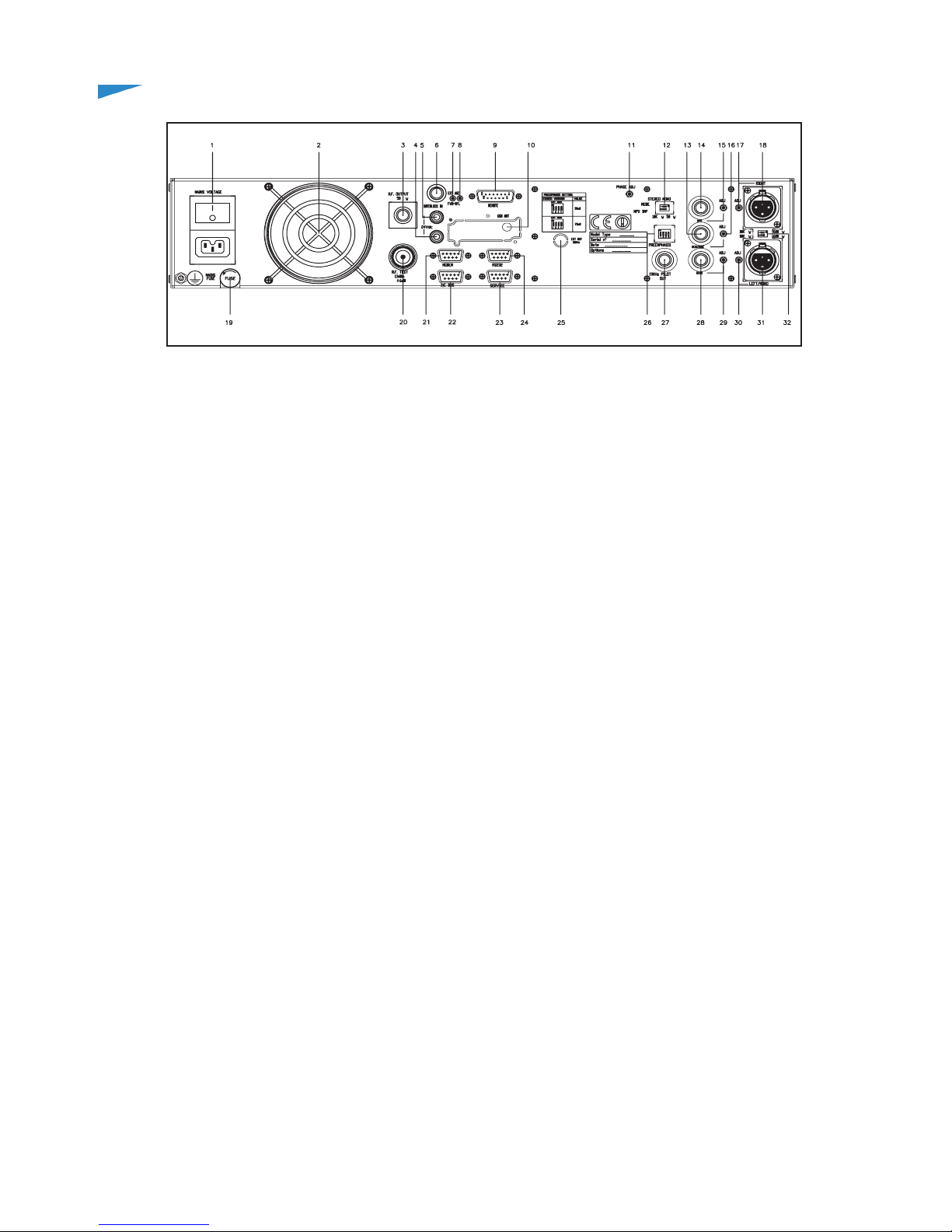
[1] PLUG VDE plug for mains supply.
[2] VENTOLA Fan for the forced ventilation of the exciter.
[3] R.F. OUTPUT RF output connector, N-type, 50Ω.
[4] 24 VDC IN- External 24Vdc supply input. Negative (black). Only for
TEX30/50/100/150LCD.
[5] 24 VDC IN- External 24Vdc supply input. Positive (red). Only for TEX30/
50/100/150LCD.
[6] INTERLOCK OUT Connettore BNC di interlock in uscita: quando l’eccitatore
entra in modalità stand-by, il conduttore centrale,
normalmente ottante, viene posto a massa
[7] FWD EXT. AGC Trimmer for the control of the delivered power in function of
the FWD fold input.
[8] RFL EXT. AGC Trimmer for the control of the delivered power in function of
the RFL fold input.
[9] REMOTE DB15 connector for telemetry of the machine.
[10] GSM ANT Reserved for Future Uses - SMA connector for GSM
Antenna.
[11] PHASE ADJ Pilot tone phase adjustment trimmer.
[12] MODE/MPX IMP Dip-switch to set the operation mode (STEREO or MONO)
and the MPX input impedance, 50Ω or 10kΩ.
[13] SCA/RDS BNC connector, SCA/RDS unbalanced input.
[14] MPX BNC connector, MPX unbalanced input.
[15] MPX ADJ Adjustment trimmer for MPX input.
[16] SCA/RDS ADJ Adjustment trimmer for SCA/RDS input.
[17] RIGHT ADJ Adjustment trimmer for the Right channel input.
[18] RIGHT XLR connector, balanced Right channel input.
[19] FUSE BLOCK Fuse carrier.Use a screwdriver to access the fuse.
[20] R.F. TEST RF test output, approx. 13 dBm wrt the RF output power
level. Not suitable for spectral analysis.
[21] MODEM DB9 connector connected to GSM modem (only with
telemetry option).
[22] I
2
C BUS Normally not used, or used for customized functions (only
with telemetry option).
[23] RS232 DB9 connector for direct serial communication or modem
(only with telemetry option).
[24] SERVICE DB9 connector for interconnection with other devices
and for factory parameters programming (only for factory
programming).
[25] EXT REF 10MHz Fine regulation trimmer for frequency transmission.
Optionally, Sync signal input BNC connector for external
devices.
[26] PREEMPHASIS Dip-switch to set the preenphasys at 50 or 75 μs. The
preenphasys setting is relevant only for the Left and Right
inputs in stereo mode and for the mono input in mono mode,
SBFM100SS Transmitter User Manual
6
Superior Broadcast
Page 11
TEX30/50/100/150/300/502/702LCD
ELETTRONICA
while MPX input is unaffected by this setting.
[27] 19 kHz PILOT OUT BNC output for the 19 kHz pilot tone. This can be used for
external devices (e.g. RDS coders) synchronization.
[28] SCA2 BNC connector, SCA2 unbalanced input.
[29] SCA2 ADJ Adjustment trimmer for SCA2 input.
[30] LEFT-MONO ADJ Adjustment trimmer for Left-Mono channel input.
[31] LEFT-MONO XLR connector, balanced Left-Mono channel input.
[32] IMPEDANCE Dip-switch to set the balanced input impedance, 600Ω or
10kΩ.
4.5 Connectors Description
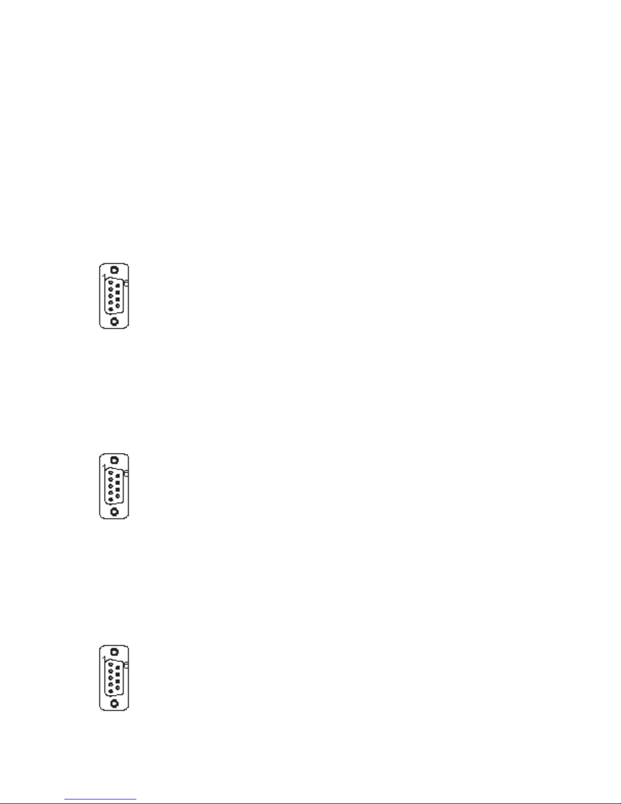
4.5.1 RS232
Type: Female DB9
1 NC
2 SDA
3 SCL
4 NC
5 GND
6 NC
7 NC
8 NC
9 NC
4.5.2 Service (for programming of factory parameters)
Type: Female DB9
1 NC
2 TX_D
3 RX_D
4 Internally connected with 6
5 GND
6 Internally connected with 4
7 Internally connected with 8
8 Internally connected with 7
9 NC
4.5.3 I2C Bus
Type: Male DB9
1 NC
2 TX_D
3 RX_D
4 Internally connected with 6
5 GND
6 Internally connected with 4
7 Internally connected with 8
8 Internally connected with 7
9 NC
Superior Boadcast SBFM100SS Transmitter
Superior Broadcast
7
SBFM100SS Transmitter User Manual
Page 12

Superior Broadcast SBFM100SS Transmitter
ELETTRONICA
(MONO) / Right
Type: Female XLR
1 GND
2 Positive
3 Negative
Type: Female DB15
Pin Name Type Meaning
1 Interlock IN By passes power if closed at GND
2 Ext AGC FWD IN Ext. signal,1-12V, for power
limitation (AGC)
3 GND Ground
4 SDA IIC I/O IIC communication serial data
5 VPA Tlm ANL OUT PA power supply voltage 3,9V F.S.
6 FWD Tlm ANL OUT Forward power 3,9V F.S.
7 Power Good DIG OUT Open collector, enabled whenpower
exceeds the set threshold
8 GND Ground
9 GND Ground
10 Ext AGC RFL IN Ext. signal.,1-12V, for power
limitation (AGC)
11 SCL IIC I/O IIC communication clock
12 IPA Tlm ANL OUT PA power supply current 3,9V F.S.
13 RFL Tlm ANL OUT Reected power 3,9V F.S.
14 On cmd DIG IN One grounded pulse (500 ms)
enables power supply
15 OFF cmd DIG IN One grounded pulse (500 ms)
disables power supply
SBFM100SS Transmitter User Manual
8
Superior Broadcast
Page 13
TEX30/50/100/150/300/502/702LCD
ELETTRONICA
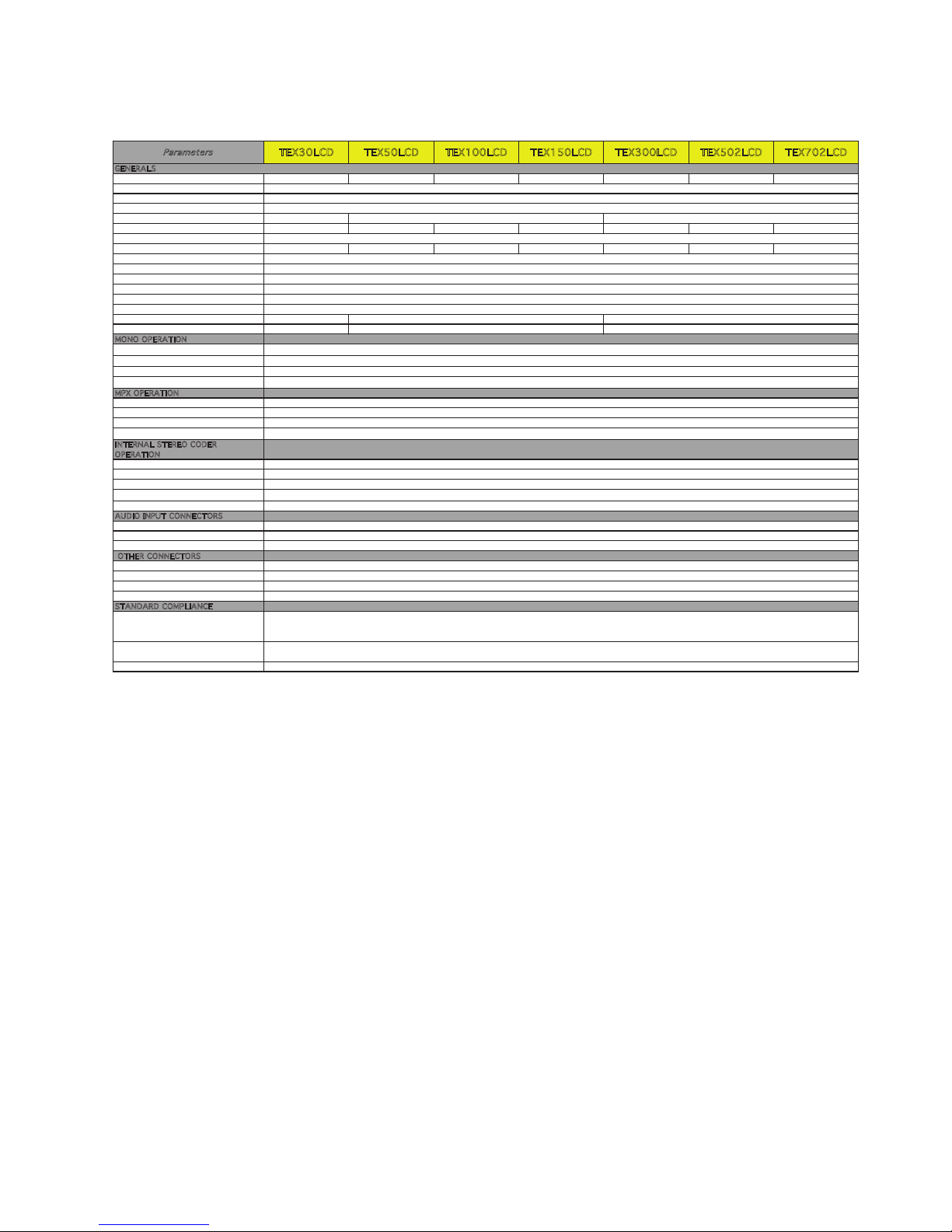
4.6 Technical Description
Parameters
TEX30LCD TEX50LCD TEX100LCD TEX150LCD TEX300LCD TEX502LCD TEX702LCD
GENERAL S
Rated output power 30W 50W 100W 150W 300W 500W 700W
Frequency range
Operational Mode
Modulation type
Primary Power
80 ÷ 260 Vac or 24
AC Power Consumption 130 VA / 70W 200 VA /100W 330 VA / 212 W 440 VA / 260 W 560 VA / 520 W 970VA / 940W 1280VA / 1240W
Phisical Dimensions (W x H x D)
Weight 7 kg 8,5 kg 8,5 kg 8,5 kg 9,5 kg 10 kg 10 kg
Environmental Working Conditions
Cooling
Frequency programmability
Frequency stability
Pre-emphasis mode
Spurious & harmonic suppression
Asynchronous AM S/N ratio ≥ 65 dB (typical 70)
Synchronous AM S/N ratio ≥ 50 dB (typical 60)
MONO OPE RATION
S/N FM Ratio
Frequency Response
Total Harmonic Distortion
Intermodulation distortion
MPX OPERA TION
Composite S/N FM Ratio
Frequency Response
Total Harmonic Distortion
Intermodulation distortion
INTERNA L STEREO CODER
O
PERATIO N
Stereo S/N FM Ratio
Frequency Response
Total Harmonic Distortion
Intermodulation distortion
Stereo separation
AUDIO INPUT CO NNECTORS
Left / Right
MPX unbalanced/RDS
SCA/RDS
OTHER CONNECTO RS
RF Output
RF Monitor
Pilot output
Interlock Input
STANDA RD COMPLI ANCE
Safety
EMC
Radio
BNC (- 30dBr referred to RF output )
BNC (1Vpp)
BNC
> 50 dB 30 Hz ÷ 15 kHz (typical 55 dB)
XLR balanced; Impedance: 10 k or 600 ohm; Level: -13 to +13 dBu
BNC unbalanced; Impedance: 10 k or 50 ohm; Level: -13 to +13 dBu
2 x BNC unbalanced; Impedance: 10 k; Level: -8 to +13 dBu
N (50 ohm)
< 0.1% 30Hz ÷ 53kHz
< 0.05% with 1 kHz and 1,3 kHz tones
> 75 dB RMS (typical 78dB)
± 0.5 dB 30 Hz ÷ 15 kHz
< 0.05% 30 Hz ÷ 15 kHz
≤ 0.03% with 1 kHz and 1,3 kHz tones
> 80 dB RMS (typical 85 dB)
< ± 0.5 dB 30Hz ÷ 15kHz (typical ± 0.2 dB)
< 0.1 % 30 Hz ÷ 15 kHz (typical 0.07 %)
< 0.02 % with 1 kHz and 1,3 kHz tones
> 80 dB RMS (typical 85 dB)
± 0.2 dB 30Hz ÷ 53kHz / ± 0.5 dB 53kHz ÷ 100 kHz
EN 301 489-1 V1.4.1 (2002-08)
EN 301 489-11 V1.2.1 (2002-11)
EN 302 018-2 V1.2.1 (2005-06)
80 ÷ 260 Vac
-10 ÷ +50 °C / 95% relative Humidity non condensing
Forced, with internal fan
From software, with 10 kHz steps
±1 ppm
≥ 50 dB (typical 55)
EN 60215:1989
EN60215/A1:1992-07
EN60215/A2:1994-09
≥ 50 dB (typical 58)
FCC -CCIR - OIRT - JPN
0/50 (CCIR) μS, 75 (FCC) μS
<75 dBc (80 typical)
≥ 60 dB (typical 65)
Mono, Stereo, Multiplex
F3E
483 x 88 x 394 mm
115 / 230 ±15% or 28 Vdc
≥ 60 dB (typical 68)
Superior Boadcast SBFM100SS Transmitter
Superior Broadcast
9
SBFM100SS Transmitter User Manual
Page 14

Superior Broadcast SBFM100SS Transmitter
TEX30/50/100/150/300/502/702LCD
ELETTRONICA
5. Quick guide for installation and use
This section provides a step-by-step description of equipment installation and
conguration procedure. Follow these procedures closely upon rst power-on
and each time any change is made to general conguration, such as when a new
transmission station is added or the equipment is replaced.
Once the desired conguration has been set up, no more settings are required
for normal operation; at each power-up (even after an accidental shutdown),
the equipment defaults to the parameters set during the initial conguration
procedure.
The topics covered in this section are discussed at greater length in the next
sections, with detailed descriptions of all hardware and rmware features and
capabilities. Please see the relevant sections for additional details.
IMPORTANT: When conguring and testing the transmitter in which the equipment
is integrated, be sure to have the Final Test Table supplied with the equipment ready
at hand throughout the whole procedure; the Final Test Table lists all operating
parameters as set and tested at the factory.
5.1 Prepation
5.1.1 Preliminary checks
Unpack the exciter and immediately inspect it for transport damage. Ensure that
all connectors are in perfect condition.
The main fuse can be accessed from the outside on the rear panel. Extract the
fuse carrier with a screwdriver to check its integrity or for replacement, if necessary.
The fuse to be used is this type:
Fusibile principale
TEX30LCD
@ 90÷260 Vac
(1x) 3.15A tipo 5x20
TEX50/100/150LCD
@ 230 Vac/115 Vac
(1x) 6.3A tipo 5x20
TEX300/502/702LCD
@ 230 Vac/115 Vac
(1x) 8A tipo 5x20
Table 5.1: Fuses
Provide for the following (applicable to operating tests and putting into service):
√ Single-phase 230 VAC or 115 VAC (-15% / +10%) mains power supply for
TEX50/100/150LCD, or 80÷260 VAC full-range mains power supply for TEX30/
300/502/702LCD, with adequate earth connection.
√ For operating tests only: dummy load with 50 Ohm impedance and adequate
SBFM100SS Transmitter User Manual
10
Superior Broadcast
Page 15
Superior Boadcast SBFM100SS Transmitter
TEX30/50/100/150/300/502/702LCD
ELETTRONICA
capacity (30W for TEX30LCD, 50W for TEX50LCD, 100W for TEX100LCD,
150W for TEX150LCD, 300W for TEX300LCD, 500W for TEX502LCD or 700W
for TEX702LCD as a minimum).
√ Connection cable kit including:
• Mains power cable
• Coaxial cable with BNC connectors for interlock signal connection
• RF cable for output to load / antenna (50 Ohm coaxial cable with N-type
connector)
• Audio cables between transmitter and audio sources.
5.1.2 Connections
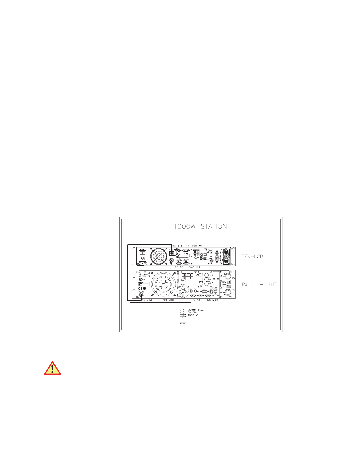
Connect the RF output of the transmitter to the antenna cable or a dummy load
capable of dissipating amplier output power. To begin with, set exciter to minimum
output power and switch it off.
Connect the transmitter INTERLOCK IN input to the matching INTERLOCK OUT
output tted on R.V.R. Elettronica equipment to act as hybrid couplers. If your
equipment is a different brand, identify an equivalent output.
WARNING: Electric shock hazard! Never handle the RF output connector
when the equipment is powered on and no load is connected. Injury or death
may result.
Ensure that the POWER switch on the front panel of TEX30/50/100/150/300/502/
702LCD is set to “OFF”.
Superior Broadcast
Figure 5.2: connections with amplier
11
SBFM100SS Transmitter User Manual
Page 16

Superior Broadcast SBFM100SS Transmitter
TEX30/50/100/150/300/502/702LCD
ELETTRONICA
The exciter has two switches: one is embedded in VDE socket for mains power
cord and interrupts all mains power supply of the machine, while the second is on
the front panel and acts by inhibiting the switching power supply of the machine.
Connect the mains power cable to the MAINS connector on the rear panel.
Note: the mains must be equipped with adequate earth connection properly
connected to the equipment. This is a pre-requisite for ensuring operator safety
and correct operation.
Connect the audio and RDS/SCA signals from user’s sources to the transmitter
input connectors.
5.2 First power-on and setup
Seguire le istruzioni riportate di seguito nel caso di prima accensione o dopo aver
effettuato un cambiamento alla congurazione dell’eccitatore nel quale questo
componente è integrato.
Note : Standard factory settings are RF output power off (Pwr OFF) and regulated
output power set to upper limit (unless otherwise specied by customer).
5.2.1 Power-on
When you have performed all of the connections described in the previous
paragraph, power on the exciter using the suitable power switch on the front
panel.
5.2.2 Power check
Ensure that the ON LED turns on. Equipment name should appear briey on the
display, followed by forward power and modulation readings. If the RF output is
disabled, those readings will be zero.
When the PLL locks to operating frequency, the LOCK LED will turn on.
5.2.3 How to enable the RF output
Check output power level and set it to maximum level (unless it has already been
set) from the Power Setup menu that you will have accessed by pressing the
following sequence of key: ESC (opens Default Menu) ⇒ ENTER (hold down for
2 seconds) ⇒ SET ⇒ use keys to set bar to upper limit (gure 5.2 - menu 2).
Check the state of the Pwr output power by the Fnc menu. If it is set to OFF, press
ENTER to bring the selection to ON.
SBFM100SS Transmitter User Manual
12
Superior Broadcast
Page 17

Superior Boadcast SBFM100SS Transmitter
TEX30/50/100/150/300/502/702LCD
ELETTRONICA
5.2.4 Controllo del livello di potenza di uscita
Note: The exciter incorporates Automatic Gain Control (AGC) and output power is
modulated based on the power level set by the user and actual operating conditions,
such as temperature, reected power and other parameters. Please read section
5.3 for more details of RF power modulation.
Access the Power Setup Menu pressing the following keys in the order:
ESC (opens Default Menu) ⇒ ENTER (hold down for 2 seconds)
Use the keys
and in the SET menu to set exciter output power; the setting bar
at the side of SET provides a graphic indication of power setting; please consider
that the forward power readout provided on the display (FWD: xxxx W) reects
actual output power reading, which may be lower than regulated power supply
when Automatic Gain Control is running in power supply limitation mode
(please read section 5.3 about RF power supply modulation for more details).
Note: Output power may be set using the Pwr OFF control. In this condition, the
output power readout (Fwd) on the display will read 0 (zero); the SET bar will reect
any adjustments you make using the keys and provides a graphic indication of how
much power supply will be delivered the moment you return to Pwr On state.
5.2.5 Changing the Power Good alarm threshold
Change Forward Power Good alarm setting PgD from the Fnc menu as desired
(factory setting is 50%).
5.2.6 Setting equipment I2C address
Change the IIC address in the MIX (Miscellaneous) menu as desired (factory
setting is 01).
5.2.7 Adjustments and calibration
The only manual adjustments are the level adjustments and the audio mode
adjustment.
The rear panel holds the trimmers for all exciter inputs. Trimmer identication is
printed on the rear panel. Input sensitivity can be set within the limits set out in
the tables below through the trimmers:
Superior Broadcast
13
SBFM100SS Transmitter User Manual
Page 18
Superior Broadcast SBFM100SS Transmitter
TEX30/50/100/150/300/502/702LCD
ELETTRONICA
Input sensitivity:
Input Figure 6.2 Trimmer Sensitivity Notes
SCA1/
RDS
[13] [16] - 8 ÷ +13 dBu
SCA2 [28] [29] - 8 ÷ +13 dBu
Input level for 7,5 kHz overall deviation
(- 20 dB)
MPX [14] [15] -13 ÷ +13 dBu
Left/
Mono
[31] [30] -13 ÷ +13 dBu
Right [18] [17] -13 ÷ +13 dBu
Input level for 75 kHz overall deviation
(0 dB)
When setting input sensitivity, please consider that the default menu reports
instantaneous modulation level and an indicator provides a 75 kHz reading. To
ensure correct adjustment, apply a signal with the same level as user’s audio
broadcast maximum level and then adjust using the trimmer until instantaneous
deviation matches the 75 kHz reading.
To set subcarrier input levels, you may use the same procedure and option “x10”
available in the Fnc menu. With this option, modulation level is multiplied by a factor
of 10, which means that default menu bar meter reects a 7.5 kHz deviation.
A special menu with separate indications of Left and Right channel levels and
relating indicators of nominal levels for maximum deviation (75 kHz) is provided.
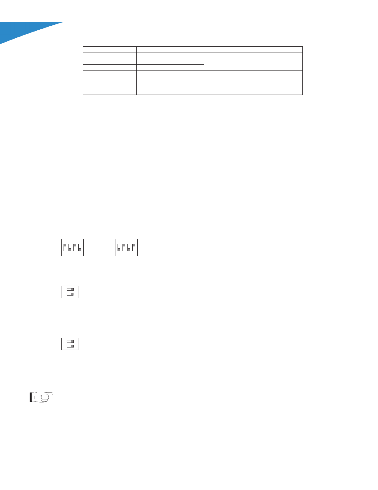
• Preemphasis:
ON
123
4
50 ms
ON
1
2
3
4
75 ms
• L and R (XLR type) input impedance:
Switch 1: R XLR input impedance, ON = 600 W, OFF = 10 kW
Switch 2: L XLR input impedance, ON = 600 W, OFF = 10 kW
• MPX input operation mode/impedance:
Switch 1: Mode of operation ON = Mono, OFF = Stereo
Switch 2: MPX input impedance, ON = 50
W, OFF = 10 kW
5.3 Operation
NOTE: For better clarity, only the typical screens of TEX702LCD are reported
below. TEX30/50/100/150/300/502LCD screens look the same except that full
scale values are different.
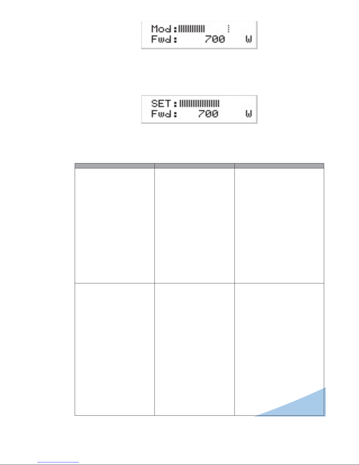
1) Power on the exciter and ensure that the ON light turns on. Equipment name
should appear briey on the display, quickly followed by modulation and
forward power readings (Menu 1), provided that the exciter is delivering output
power.
ON
1 2
ON
1 2
SBFM100SS Transmitter User Manual
14
Superior Broadcast
Page 19
Superior Boadcast SBFM100SS Transmitter
TEX30/50/100/150/300/502/702LCD
ELETTRONICA
Menu 1
1b) To modify power level setting, hold down the ENTER button until opening
the power setup menu.
The edit screen will look like this:
Menu 2
Next to SET indication, a bar provides a graphic display of preset output power.
The lled portion of the bar is proportional to set power level.
Example
100% potenza di uscita Barra piena
≅ 700W in uscita
(mod.TEX702LCD)
≅ 500W in uscita
(mod.TEX502LCD)
≅ 300W in uscita
(mod.TEX300LCD)
≅ 150W in uscita
(mod.TEX150LCD)
≅ 100W in uscita
(mod.TEX100LCD)
≅ 50W in uscita
(mod.TEX50LCD)
≅ 30W in uscita
(mod.TEX30LCD)
25% potenza di uscita 1/4 della barra
≅ 175W in uscita
(mod.TEX702LCD)
≅ 125W in uscita
(mod.TEX502LCD)
≅ 75W in uscita
(mod.TEX300LCD)
≅ 700W in uscita
(mod.TEX702LCD)
≅ 37,5W in uscita
(mod.TEX150LCD)
≅ 25W in uscita
(mod.TEX100LCD)
≅ 12,5W in uscita
(mod.TEX50LCD)
≅ 7,5W in uscita
(mod.TEX30LCD)
Superior Broadcast
15
SBFM100SS Transmitter User Manual
Page 20

Superior Broadcast SBFM100SS Transmitter
TEX30/50/100/150/300/502/702LCD
ELETTRONICA
The bottom line provides instantaneous power reading (700W for TEX702LCD
shown here), press button
to increase level, press to decrease it. When
you have achieved the desired level, press ENTER to conrm and exit the default
menu. Please note that the setting is stored automatically; in other words, if you
press ESC or do not press any keys before the preset time times out, the latest
power level set will be retained.
NOTE: This feature prevents the equipment from delivering maximum power
as soon as output is enabled from menu 4, or in the event the equipment is
already set to ON when you energise it.
2) Ensure that the equipment is not in a locked-out state. Press ESC to call up
the selection screen (menu 3). Highlight Fnc and press ENTER to conrm and
access the selected menu (menu 4).
If PWR is set to OFF, i.e. power output is disabled, move cursor to PWR. Press
ENTER and label will switch to ON, i.e. power output is enabled.
Press ESC twice to go back to the default menu (menu 1).
3) Fine tune power setting from menu 2 (see description of item 1b) until achieving
the desired value.
WARNING: Equipment is capable of delivering more than rated output power
(30/50/100/150/300/500/700 W for TEX30/50/100/150/300/502/702LCD
respectively); however, never exceed the specied power rating.
NOTE: If power is set to 0 W in the Power Setup Menu, the INTERLOCK OUT
contact is activated and any external appliances connected to it are immediately
inhibited.
Next, you can review all operating parameters of the equipment through the
management rmware.
Normally, the equipment can run unattended. Any alarm condition is handled
automatically by the safety system or is signalled by the LED indicators on the
panel or by display messages.
NOTE: Standard factory settings are output power set to upper limit (unless
otherwise specied by customer) and OFF.
5.4 Management Firmware
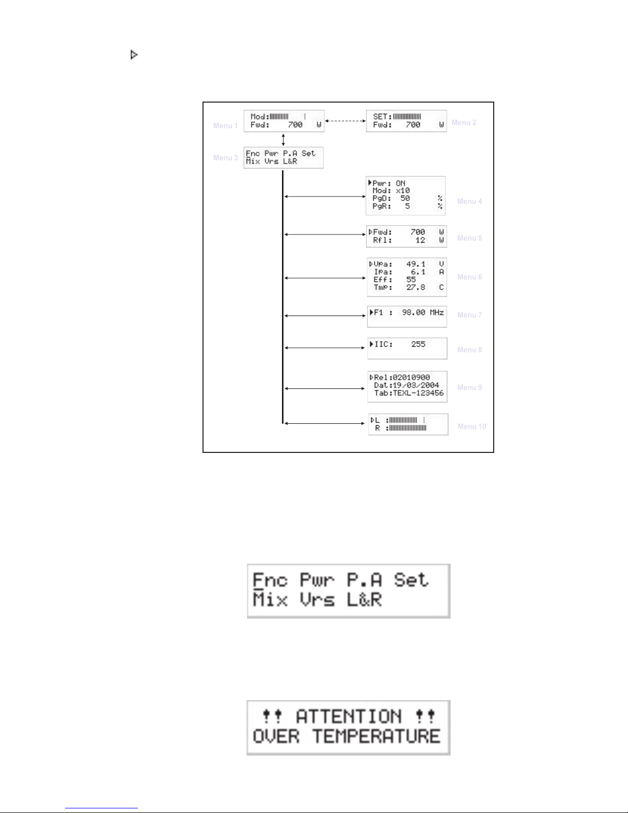
The equipment features an LCD with two lines by 16 characters that displays a
set of menus. The gure below provides an overview of equipment menus.
The symbols listed below appear in the left portion of the display as appropriate:
(Cursor) - Highlights selected (i.e. accessible) menu.
(Filled arrow) - Editable parameter marker. This symbol appears in menus that
take up more than two lines to aid browsing.
(Three empty arrows) - Parameter is being edited.
SBFM100SS Transmitter User Manual
16
Superior Broadcast
Page 21
Superior Boadcast SBFM100SS Transmitter
TEX30/50/100/150/300/502/702LCD
ELETTRONICA
(Empty arrow) - Current line marker; the parameter in this line cannot be
edited. This symbol appears in menus that take up more than two lines to aid
browsing.
Menu 1
Menu 3
Predefined menu
Selection Menu
Menu 2
Power Adjustment Menu
Menu 4
Operation Menu
Menu 5
Power Menu
Menu 6
Power Amplifier Menu
Menu 7
Settings Menu
Menu 8
Miscellaneous Menu
Menu 9
Versions Menu
Menu 10
Channels Menu
Figure 5.2
When the display is off, touching any key will turn on backlighting.
When the display is on, pressing the ESC button from the default menu (menu 1)
calls up the selection screen (menu 3), which gives access to all other menus:
Menù 3
If the temperature alarm is enabled and the alarm threshold is exceeded, the
following screen will be displayed (only if you are in the default screen):
Superior Broadcast
17
SBFM100SS Transmitter User Manual
Page 22

Superior Broadcast SBFM100SS Transmitter
TEX30/50/100/150/300/502/702LCD
ELETTRONICA
As soon as operating conditions are restored, power output is re-enabled with the
same settings in use prior to the alarm condition.
Under 20kHz, no modulation occurs. After a preset time of about 5 minutes (not
editable), a NO AUDIO condition is indicated in the main screen, but power is not
inhibited.
To gain access to a submenu, select menu name (name is highlighted by cursor)
using button or and press the ENTER button.
To return to the default menu (menu 1), simply press ESC again.
State 2
5.4.1 Operation Menu (Fnc)
In this menu, you can toggle exciter power output On/Off, set deviation display
mode and the threshold rate for Forward (PgD) or Reected (PgR) Power
Good.
To edit an item, highlight the appropriate line using the
and then press and hold the ENTER button until the command is accepted.
This way, Pwr setting is toggled between On and Off and Mod setting is toggled
between “x1” and “x10”. To edit the Power Good rate, simply select item “PgD” or
“PgR” and edit its value using the UP and DOWN buttons; nally, press ENTER
to conrm.
and buttons
Pwr Enables (ON) or disables (OFF) exciter power output.
Mod Modies modulation display (toggles between “x1” and “x10”). In “x10”
mode, instantaneous deviation indication is multiplied by a factor of 10,
and the bar meter on the default menu will reect 7.5 kHz instead of
SBFM100SS Transmitter User Manual
Menu 4
18
Superior Broadcast
Page 23

Superior Boadcast SBFM100SS Transmitter
TEX30/50/100/150/300/502/702LCD
ELETTRONICA
75 kHz. This display mode is convenient when you wish to display low
deviation levels, such as those caused by pilot tone or subcarriers.
PgD Modies Power Good threshold for forward power. The Power Good rate
is a percent of equipment rated power (30/50/100/150/300/500/702 W
for TEX30/50/100/150/300/502/702LCD respectevely), not of forward
output power. This means that this threshold set at 50% will give
15/25/50/75/150/250/350 W, respectively, regardless of set power level.
The Power Good feature enables output power control and reporting.
When output power drops below set Power Good threshold, the
equipment changes the state of pin [7] of the DB15 “Remote” connector
located on the rear panel.
PgR Modies Power Good threshold for reected power. The Power Good
rate is a percent of equipment rated power (3/5/10/15/30/50/70 W for
TEX30/50/100/150/300/502/702LCD respectevely), not of reected
output power. This means that this threshold set at 5% will give 0,15
/0,25/0,50/0,75/1,5/2,5/3,5 W , respectively, regardless of set power
level. The Power Good feature enables output power control and alarm
management.
NOTE: This alarm does not trip any contacts in the DB15 “Remote” connector and
is only available in systems equipped with telemetry.
5.4.2 Power menu(Pwr)
This screen holds all readings related to equipment output power:
Fwd Forward power reading.
R Reected power reading.
Note that these are readings, rather than settings, and cannot be edited (note
the empty triangle). To change power setting, go to the default menu as outlined
earlier.
Menu 5
Superior Broadcast
19
SBFM100SS Transmitter User Manual
Page 24
Superior Broadcast SBFM100SS Transmitter
ELETTRONICA
5.4.3 Power
5.4.4 Setup
Amplier (P.A) Menu
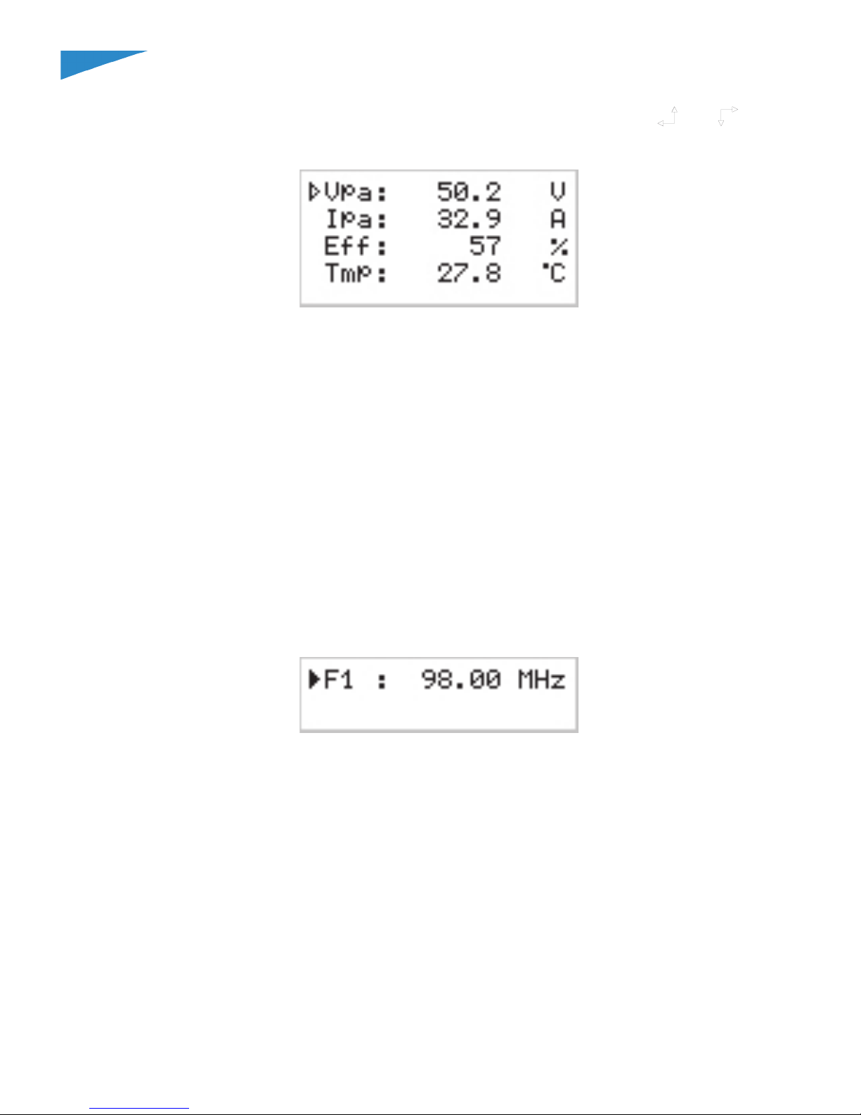
This screen is made up of four lines that can be scrolled using the and
buttons and shows the readings relating to nal power stage:
Menu 6
Note that these are readings, rather than settings, and cannot be edited (note the
empty arrow).
VPA Voltage supplied by amplier module.
IPA Current draw of amplier module.
Eff Efciency based on ratio of forward power to amplier module power,
in percent ( FWD PWR/(Vpa x Ipa) % ).
Tmp Equipment internal temperature reading.
Menu (Set)
This menu lets you view and set operating frequency.
Menu 7
F1 Operating frequency setup. Set a new frequency value and then press the
ENTER button to conrm your selection; the exciter unlocks from current
frequency (the LOCK LED turns off) and will lock to the new operating
frequency (LOCK turns back on again).
If you press ESC or let the preset time time out, the previous frequency
setting is retained.
SBFM100SS Transmitter User Manual
20
Superior Broadcast
Page 25
TEX30/50/100/150/300/502/702LCD
ELETTRONICA
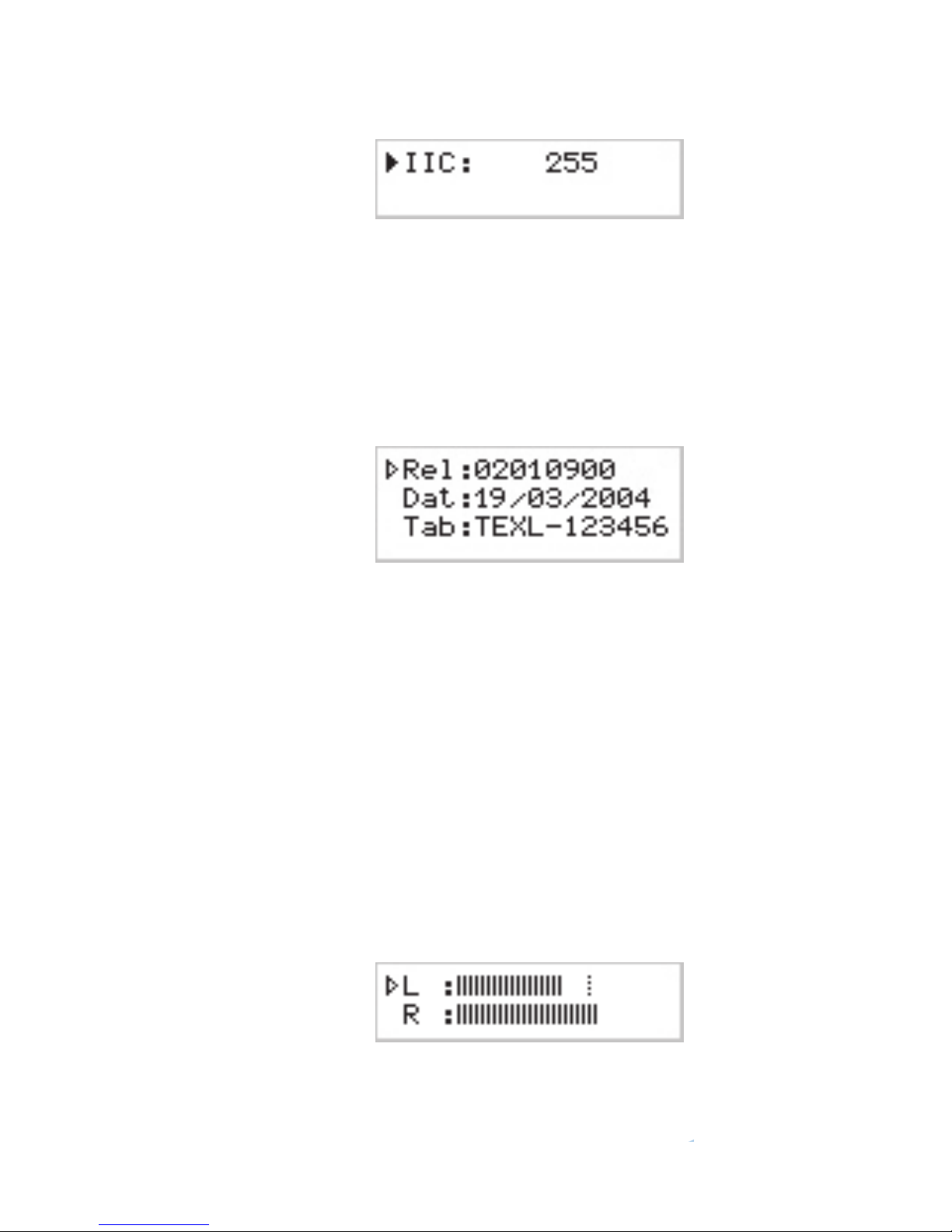
5.4.5 Miscellaneous Menu (Mix)
This menu lets you set equipment address in an I2C bus serial connection:
Menu 8
IIC
I2C address setting. The I2C network address becomes signicant when
the exciter is connected in an RVR transmission system that uses this
protocol. Do not change it unless strictly required.
5.4.6 Version Menu (Vrs)
This screen holds equipment version/release information:
Menu 9
Note that these are readings, rather than settings, and cannot be edited (note the
empty arrow).
Rel
Firmware release information.
Dat
Release date.
Tab
Shows table loaded in the memory.
5.4.7 Channels Menu (L&R)
Right and left channel input levels are displayed as horizontal bars as shown in
the gure below.
The bar meter reects the level corresponding to a 100% deviation for each channel
and provides a convenient reference when setting audio channel input levels.
Menù 10
L
Left channel Vmeter.
R
Right channel Vmeter..
Superior Boadcast SBFM100SS Transmitter
Superior Broadcast
21
SBFM100SS Transmitter User Manual
Page 26

Superior Broadcast SBFM100SS Transmitter
TEX30/50/100/150/300/502/702LCD
ELETTRONICA
5.5 Optional Function
A range of options is available for the product to add certain functions and/or modify
existing functions. Outlined below are the functions available at the moment, which
must be specied on order.
5.5.1 FSK Option
The FSK function generates periodic carrier frequency shifts to generate a
Morsecoded station ID code.
NOTE: This function is typically used in the USA.
The factory setting for frequency shift is +10KHz and code repetition period is 60
minutes (please contact R.V.R. Elettronica if you need different settings), whereas
station identied may be programmed by the user following the indications provided
in section below.
When the FSK option is tted, an FSK submenu is added to the selection
menu.
Menu 11
Press the ENTER key when FSK is highlighted in the selection menu to access
the FSK submenu:
Menu 12
FSK
Enables / disables FSK code transmission.
Cod
Shows the Morse code sent normally.
5.5.1.1 Changing the ID code
User may change the FSK code used as a station identier at any time.
This procedure requires:
• 1 RS232 male-female cable;
• Hyper Terminal interface (make sure it has been installed together with
Windows®) or equivalent serial communication software.
SBFM100SS Transmitter User Manual
22
Superior Broadcast
Page 27

Superior Boadcast SBFM100SS Transmitter
TEX30/50/100/150/300/502/702LCD
ELETTRONICA
A brief description of the procedure is provided below:
• Connect the PC serial port COM to the SERVICE connector on the rear panel
of TEX30/50/100/150/300/502/702LCD using a standard Male DB9 - Female
DB9 serial cable.
• Power on the exciter;
• Launch the serial communication software;
• Set communication parameters as follows:
Baud Rate: 19200
Data Bit: 8
Parity: None
Stop Bit: 1
Flow control: None;
• Activate Caps-Lock through the communication software and send string CODE
followed by the 6-character station ID code followed by Enter.
NOTE: To be treated as valid, the code must be made up of 6 alphanumeric
characters and must contain no blank spaces; if acknowledged as valid, code is
echoed back to the terminal, illegal codes are not echoed.
5.5.2 Power UP/DOWN Option
The Power UP/DOWN option modies the signal receive function for the signals
present at the telemetry connector.
RF section on / off control signals are treated as control signals for RF output
power level to allow for UP/DOWN setting.
The UP or DOWN command is provided by switching the corresponding signal at
the connector to ground for at least 500mS (pin features internal pull-up to power
supply).
Conguration of DB15F telemetry connector (Remote):
Pin Standard Function UP/DOWN Power Function
14 On cmd Up cmd
Enables the RF power supply Increases the RF power supply
15 Off cmd Down cmd
Disables the RF power supply Reduces the RF power supply
Superior Broadcast
23
SBFM100SS Transmitter User Manual
Page 28
Superior Broadcast SBFM100SS Transmitter
ELETTRONICA
of the Modules
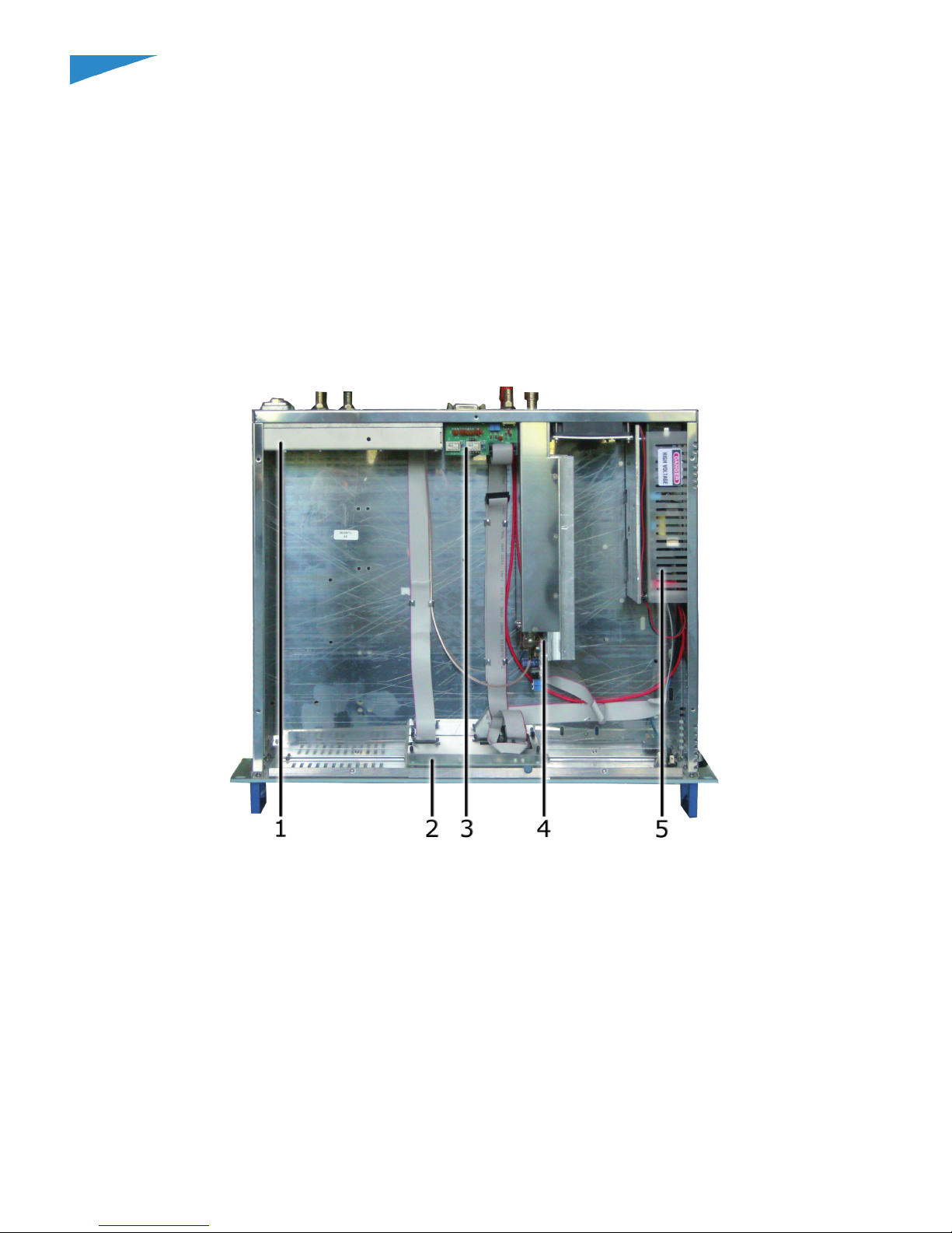
The TEX30/50/100/150/300/502/702LCD is made up of various modules linked
to each other through connectors so as to make maintenance and any required
module replacement easier.
Upper view
The gure below shows the equipment upper view with the various components
pointed out.
[1] Main Board & Stereo Coder Card (SLMBDTEXLC07 & SLCTC30V03)
[2] Panel Card (SL007PC3001)
[3] Telemetry Card (SLTLMTXLCD03)
[4] Control Card& Power Amplier (SL037BI1004 & SLPA30WMOS02)
[5] Power Supply (FLY100SMD)
SBFM100SS Transmitter User Manual
gure 8.1
24
Superior Broadcast
Page 29

TEX30/50/100/150/300/502/702LCD
ELETTRONICA
6.1.2 TEX50/100/150LCD Upper view
The gure below shows the equipment upper view with the various components
pointed out.
Superior Boadcast SBFM100SS Transmitter
gure 8.2
[1] Main Board & Stereo Coder Card (SLMBDTEXLC07 & SLCTC30V03)
[2] Panel Card (SL007PC3001)
[3] Telemetry Card (SLTLMTXLCD03)
[4] Control Card& Power Amplier (SL045DR1003 & SLPA150WMOS)
[5] Power Supply (PSL300)
Superior Broadcast
25
SBFM100SS Transmitter User Manual
Page 30
Superior Broadcast SBFM100SS Transmitter
TEX30/50/100/150/300/502/702LCD
ELETTRONICA
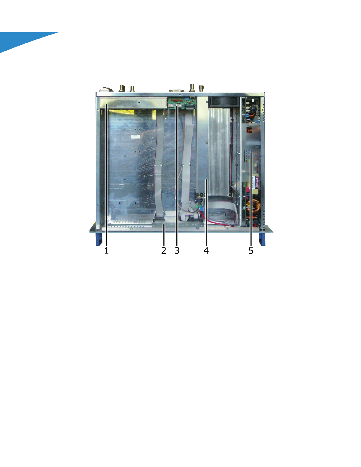
6.1.3 TEX300LCD Upper view
The gure below shows the equipment upper view with the various components
pointed out.
gure 8.3
[1] Main Board & Stereo Coder Card (SLMBDTEXLC07 & SLCTC30V03)
[2] Panel Card (SL007PC3001)
[3] Telemetry Card (SLTLMTXLCD03)
[4] Control Card& Power Amplier (SL045DR1003 & SL045RF1002)
[5] Power Supply (PSL600)
SBFM100SS Transmitter User Manual
26
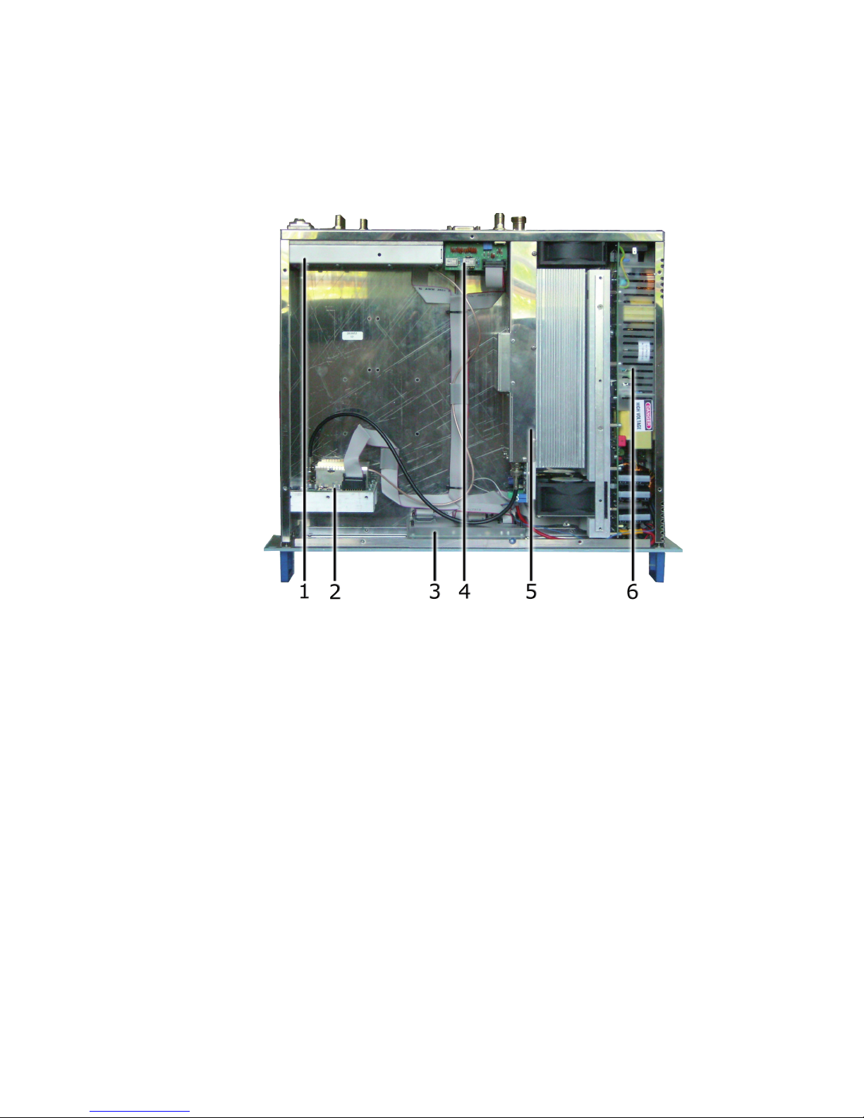
Superior Broadcast
Page 31
TEX30/50/100/150/300/502/702LCD
ELETTRONICA
6.1.4 TEX502/702LCD Upper view
The gure below shows the equipment upper view with the various components
pointed out.
Superior Boadcast SBFM100SS Transmitter
gure 8.4
[1] Main Board & Stereo Coder Card (SLMBDTEXLC07 & SLCTC30V03)
[2] Driver Card (SL175DR1002)
[3] Panel Card (SL007PC3001)
[4] Telemetry Card (SLTLMTXLCD03)
[5] Bias Card, Control Card, Low Pass Filter Card & Power Amplier - TEX502LCD model
(SL046BI1001, SL175BI1001, SL175LP1002 & SL154RF3001)
Bias Card, Cintrol Card, Low Pass Filter Card & Power Amplier - TEX702LCD model
(SL046BI1001, SL175BI1001, SL175LP1002 & SL154RF2002)
[6] Power Supply (PSL5021)
Superior Broadcast
27
SBFM100SS Transmitter User Manual
Page 32

Superior Broadcast SBFM100SS Transmitter
ELETTRONICA
7.1 TEX30/50/100/150/300/502/702LCD Common Parts
board
The panel board contains the microcontroller (PIC18F452) that implements the
equipment control software, the display and the other components needed to
interface with the user.
The board is connected with the other machine modules, both for power supply
distribution and for the control and measures.
board
The main board carries out the following functions:
• Audio and SCA input treatment
• Generation of carrier frequency
• Modulation
• R.F. amplication (Driver)
The board also features a stereophonic coder.
input section
The audio input section contains the circuits that perform the following functions:
• Input impedance selection
• 15 kHz ltering of the left and right channel
• Stereophonic Coding
• Mono channel preemphasis
• Mono, MPX and SCA channel mixing
• Clipper (limits the modulating signal level so that the frequency deviation does
not exceed 75 kHz)
• Modulating signal measurement
section
This board section generates the modulated radiofrequency signal. It is based on
a PLL scheme that uses an integrated MB15E06 type.
section
SBFM100SS Transmitter User Manual
Before passing to the nal power amplier, the RF signal is preamplied in this
28
Superior Broadcast
Page 33

TEX30/50/100/150/300/502/702LCD
ELETTRONICA
section by an ERA3 transistor. When the exciter is placed on stand-by, the driver
is by-passed.
7.1.3 Telemetry board
This board is designed to inform the user of the equipment operation state. All
input and output signals are available on the DB15 connector.
The same board also features the “INTERLOCK” BNC connector for disabling the
device. By grounding the central pin, the output power is reduced to zero until the
connection is removed.
When an R.V.R. amplier is used, this connector is linked to the power amplier
REMOTE or INTERLOCK by means of a BNC-BNC connection. In case of amplier
faults, the central conductor is grounded thus forcing the machine to enter in
stand-by mode.
Superior Boadcast SBFM100SS Transmitter
7.2 TEX30LCD Different Parts
7.2.1 Power Supply
The TEX30LCD power supply unit is a switching-type unit whose +28 V main output
powers the machineÌs RF amplier. The power supply also features stabilizers for
generating continuous +5 V and +18 V voltages for supplying the other equipment
circuits. Note that the power supply is a “direct from mains” type, or rather it is
without a transformer, and it can be connected to any voltage between 80 and
260 V without any adjustments or manual settings. The power supply unit is also
connected to
24 V auxiliary continuous voltage inputs used to automatically buffer
the mains power cutoff.
7.2.2 Power Amplier
The nal power stage is enclosed in a totally shielded metal container fastened
in the centre of the device.
The RF signal coming from the “main” card reaches the pilot, is amplied and is
then sent to the nal stage that sees to its nal amplications up to 30W.
The amplier is made in three stages. The rst is made with one BFG35, the
secondwith three BFG35 in parallel, and the last with one BLF245.
In addition to the actual RF amplication, this circuit carries out the following
functions:
• Control of the power level in output, depending on the setting
• Reduction of the power supplied when in presence of high-level reected
power
Superior Broadcast
29
SBFM100SS Transmitter User Manual
Page 34

Superior Broadcast SBFM100SS Transmitter
TEX30/50/100/150/300/502/702LCD
ELETTRONICA
• Measures of the forward and reflected power by means of directional
couplers
• Measures of the current absorbed by the power amplier
• Measures of the temperature
• Low-pass ltering of the RF signal in output
This board also features an RF sampling of approximately -30dB RF with respect
to the output, which is available on a BNC connector below the transmitter output
connector. This sample is is useful for verifying the characteristics of the carrier,
but not for verifying those of the upper harmonics.
7.2.3 Control Board
The main function of this board is to check and correct the MOSFET polarization
voltage of the RF amplier section.
It also provides the measurement of the absorbed current and contains a circuit
for signaling power supply unit faults.
If no alarms are present, the voltage is adjusted only depending on the set output
power, with a feedback mechanism based on the reading of the power really
delivered (AGC).
The voltage is also affected by other factors, such as:
• Excess of reected power.
• External AGC signals (Ext. AGC FWD, Ext. AGC RFL).
• Excess of temperature.
• Excess of absorbed current from the RF module.
7.3 TEX50/100/150LCD Different Parts
7.3.1 Power Supply
The TEX50/100/150LCD power supply unit is a switching-type unit whose +28 V
main output powers the machineÌs RF amplier. The power supply also features
stabilizers for generating continuous +5 V, -15V, +8V, +18 V and -18 V voltages
for powering the other device circuits. The power supply unit is also connected to
24 V auxiliary continuous voltage inputs used to automatically buffer the mains
power cutoff.
7.3.2 Power Amplier
The nal power stage is enclosed in a totally shielded metal container fastened
in the centre of the device.
SBFM100SS Transmitter User Manual
30
Superior Broadcast
Page 35

Superior Boadcast SBFM100SS Transmitter
TEX30/50/100/150/300/502/702LCD
ELETTRONICA
The RF signal coming from the “main” card reaches the pilot, is amplied and is
then sent to the nal stage that sees to its nal amplications up to 150W.
The amplier is made in two stages. The rst is made with BLF244 and the last
with BLF147.
In addition to the actual RF amplication, this circuit carries out the following
functions:
• Control of the power level in output, depending on the setting
• Reduction of the power supplied when in presence of high-level reected
power
• Measures of the forward and reflected power by means of directional
couplers
• Measures of the current absorbed by the power amplier
• Measures of the temperature
• Low-pass ltering of the RF signal in output
On this card is an RF sample approximately -30dB compared with the output that is
available on a BNC connector underneath the output connector of the transmitter.
This sample is useful for checking the characteristics of the carrier, but not of the
higher order harmonics.
7.3.3 Control Board
The main function of this board is to check and correct the MOSFET polarization
voltage of the RF amplier section.
It also provides the measurement of the absorbed current and contains a circuit
for signaling power supply unit faults.
If no alarms are present, the voltage is adjusted only depending on the set output
power, with a feedback mechanism based on the reading of the power really
delivered (AGC).
The voltage is also affected by other factors, such as:
• Excess of reected power.
• External AGC signals (Ext. AGC FWD, Ext. AGC RFL).
• Excess of temperature.
• Excess of absorbed current from the RF module.
Superior Broadcast
31
SBFM100SS Transmitter User Manual
Page 36

Superior Broadcast SBFM100SS Transmitter
TEX30/50/100/150/300/502/702LCD
ELETTRONICA
7.4 TEX300LCD Different Parts
7.4.1 Power Supply
The TEX300LCD power supply unit is a switching-type unit whose +50 V main
stabilizers for generating continuous +5 V, +18 V and -18 V voltages for supplying
the other equipment circuits. Note that the power supply is a “direct from mains”
type, or rather it is without a transformer, and it can be connected to any voltage
between 90 and 260 V without any adjustments or manual settings.
7.4.2 Power Amplier
The nal power stage is enclosed in a totally shielded metal container fastened
in the centre of the device.
The RF signal coming from the “main” card reaches the pilot, is amplied and is
then sent to the nal stage that sees to its nal amplications up to 300W.
The amplier is made in three stages. The rst is made with BFG35, the second
with one BLF175 and the last with one SD2942.
In addition to the actual RF amplication, this circuit carries out the following
functions:
• Control of the power level in output, depending on the setting
• Reduction of the power supplied when in presence of high-level reected
power
• Measures of the forward and reflected power by means of directional
couplers
• Measures of the current absorbed by the
power amplier
• Measures of the temperature
• Low-pass ltering of the RF signal in output
This board also features an RF sampling of approximately -60dB RF with respect
to the output, which is available on a BNC connector below the transmitter output
connector. This sample is is useful for verifying the characteristics of the carrier,
but not for verifying those of the upper harmonics.
7.4.3 Control Board
The main function of this board is to check and correct the MOSFET polarization
voltage of the RF amplier section.
It also provides the measurement of the absorbed current and contains a circuit
for signaling power supply unit faults.
SBFM100SS Transmitter User Manual
32
Superior Broadcast
Page 37

Superior Boadcast SBFM100SS Transmitter
TEX30/50/100/150/300/502/702LCD
ELETTRONICA
power, with a feedback mechanism based on the reading of the power really
delivered (AGC).
The voltage is also affected by other factors, such as:
• Excess of reected power.
• External AGC signals (Ext. AGC FWD, Ext. AGC RFL).
• Excess of temperature.
• Excess of absorbed current from the RF module.
7.5 TEX502/702LCD Different Parts
7.5.1 Power Supply
The TEX502LCD power supply unit is a switching-type unit whose +50 V main
stabilizers for generating continuous +5 V, +18 V and -18 V voltages for supplying
the other equipment circuits. Note that the power supply is a “direct from mains”
type, or rather it is without a transformer, and it can be connected to any voltage
between 90 and 260 V without any adjustments or manual settings.
7.5.2 Power Amplier
The nal power stage is enclosed in a totally shielded metal container fastened
in the centre of the device.
The RF signal coming from the “main” card reaches the pilot, is amplied and is
then sent to the nal stage that sees to its nal amplications up to 500W (for
TEX502LCD model) or up to 700W (for TEX702LCD model).
The amplication stage consists of two main blocks.
In addition to the actual RF amplication, this circuit carries out the following
functions:
• Control of the power level in output, depending on the setting
• Reduction of
power
• Measures of the current absorbed by the power amplier
• Measures of the temperature
the power supplied when in presence of high-level reected
This board also features an RF sampling of approximately -60dB RF with respect
to the output, which is available on a BNC connector below the transmitter output
connector. This sample is is useful for verifying the characteristics of the carrier,
but not for verifying those of the upper harmonics.
Superior Broadcast
33
SBFM100SS Transmitter User Manual
Page 38

Superior Broadcast SBFM100SS Transmitter
ELETTRONICA
The driver card is able to The card and drivers’ capable of delivering approximately
15W of power.
The driver stage is made in two stages. The rst is made with one BFG35 and the
last with one LD-MOS PD57006.
Stage block
The nal stage is made of two MOS-FET SD2932 (for
TEX502LCD model) or two
MOS-FET SD2942 (for TEX702LCD model).
Board
The main function of this board is to check and correct the MOSFET polarization
voltage of the RF amplier section.
It also provides the measurement of the absorbed current and contains a circuit
for signaling power supply unit faults.
If no alarms are present, the voltage is adjusted only depending on the set output
power, with a feedback mechanism based on the reading of the power really
delivered (AGC).
The voltage is also affected by other factors, such as:
• Excess of reected power.
• External AGC signals (Ext. AGC FWD, Ext. AGC RFL).
• Excess of temperature.
• Excess of absorbed current from the RF module.
Pass Filter Card
This card provide the low-pass ltering of the RF signal in output and measure the
reected and forward power output.
Card
This card controls the bias voltage and contains AGC networks for forward power,
reected power, temperature, current and EXT AGC.
SBFM100SS Transmitter User Manual
34
Superior Broadcast
Page 39

Superior Boadcast SBFM100SS Transmitter
______________________________________________________________________________
______________________________________________________________________________
______________________________________________________________________________
______________________________________________________________________________
______________________________________________________________________________
______________________________________________________________________________
______________________________________________________________________________
______________________________________________________________________________
______________________________________________________________________________
______________________________________________________________________________
______________________________________________________________________________
______________________________________________________________________________
______________________________________________________________________________
______________________________________________________________________________
______________________________________________________________________________
______________________________________________________________________________
______________________________________________________________________________
______________________________________________________________________________
______________________________________________________________________________
______________________________________________________________________________
______________________________________________________________________________
______________________________________________________________________________
______________________________________________________________________________
Superior Broadcast
35
SBFM100SS Transmitter User Manual
Page 40

Superior Broadcast SBFM100SS Transmitter
______________________________________________________________________________
______________________________________________________________________________
______________________________________________________________________________
______________________________________________________________________________
______________________________________________________________________________
______________________________________________________________________________
______________________________________________________________________________
______________________________________________________________________________
______________________________________________________________________________
______________________________________________________________________________
______________________________________________________________________________
______________________________________________________________________________
______________________________________________________________________________
______________________________________________________________________________
______________________________________________________________________________
______________________________________________________________________________
______________________________________________________________________________
______________________________________________________________________________
______________________________________________________________________________
______________________________________________________________________________
______________________________________________________________________________
______________________________________________________________________________
______________________________________________________________________________
SBFM100SS Transmitter User Manual
36
Superior Broadcast
Page 41

Superior Boadcast SBFM100SS Transmitter
______________________________________________________________________________
______________________________________________________________________________
______________________________________________________________________________
______________________________________________________________________________
______________________________________________________________________________
______________________________________________________________________________
______________________________________________________________________________
______________________________________________________________________________
______________________________________________________________________________
______________________________________________________________________________
______________________________________________________________________________
______________________________________________________________________________
______________________________________________________________________________
______________________________________________________________________________
______________________________________________________________________________
______________________________________________________________________________
______________________________________________________________________________
______________________________________________________________________________
______________________________________________________________________________
______________________________________________________________________________
______________________________________________________________________________
______________________________________________________________________________
______________________________________________________________________________
Superior Broadcast
37
SBFM100SS Transmitter User Manual
Page 42

Superior Broadcast where the Best Cost Less
Call us today. We want to talk to You
Tel: 972-473-2577 | Email: [email protected]
18208 Preston Rd. Suite D9-297, Dallas, TX 75252. www.sbp-tv.com
Superior Broadcast
Jimmie Joynt
 Loading...