


Superior Antenna
Manufacturing Inc.
Antenna
Installation Manual
This manual
covers
ALL 12ft, 1Oft, 7.lft,
and 6ft sectional
models
sM
10
QSL
7.5
PI.ACE
ANGLE FINDER ON
BACK
PI-ATE
OF
DISH AND
SET DECUNATION
A}IGLE
EOUAL
TO APEX ELEVANON
AS IIEASURED
BYAIIGLE
FINOER
AS
SHOWN
sil12
UPS
6
T'SE THIS
BOLT
TO TAKE
ATUUSTI|EilT
STEP
FIVE:
SET
FOTAR
IOTilT
ELEVANOilAflGil-E
EOUAL
TO
SITE
IIITruO€
N I'€GREES
AS ITEASURED
BY
AIIGLE FIT{T'€R
AS SHOWN
USE THIS BOLTTO
IAIG
AI'JT'STTEUT
"'*Sf,t.
I
50
.19
Q
a7
t6
/ls
tn
at
L.2
A41
-
T.O
ls
Tr.
u37
D16
Es
ta
3
&l
3l
$
a
t
n
26
a
:t.
--a
3,2.7
33.8
34.9
35.9
37.1
38.1
39.3
ao.a
415
IULC
43.7
t|{'.o
/t5.9
17.r
tts2
/fe.3
50.5
61.6
61L7
5&9
t6.o
to2
t.:73
6t-5
6e
.6
co.7
A
P
E
X
E
L
E
V
A
T
I
o
N
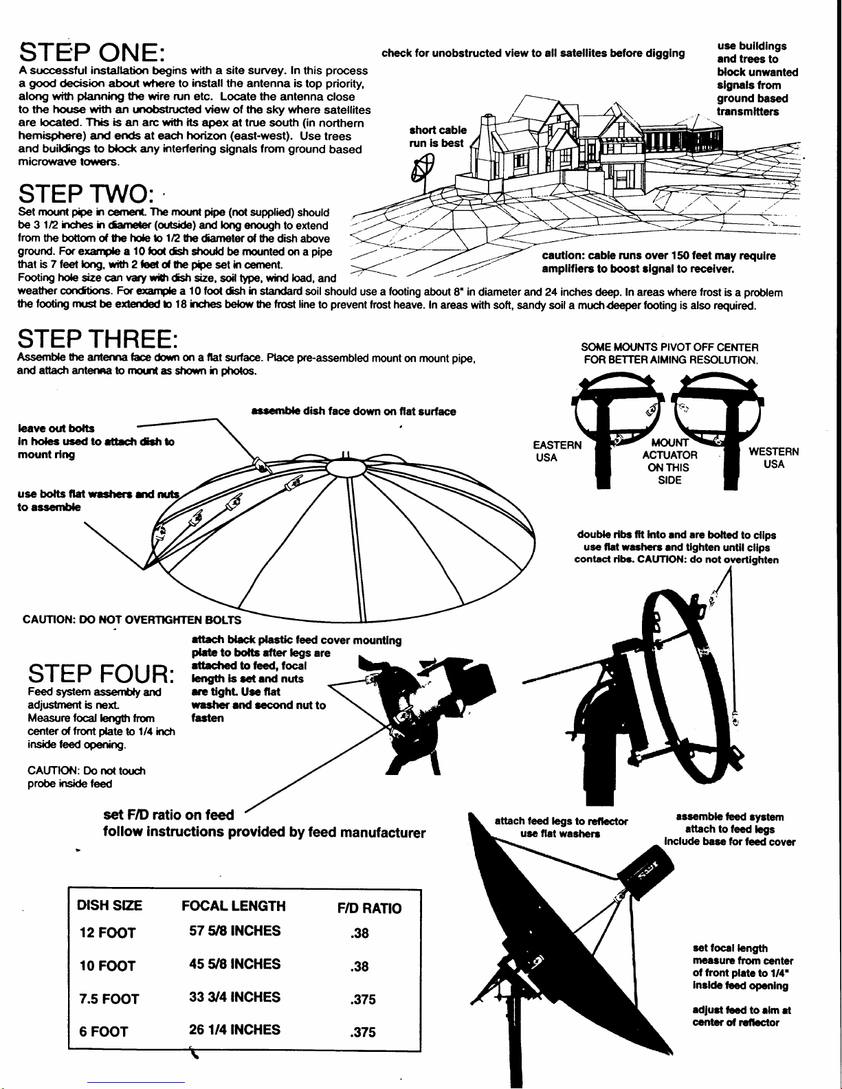
ST
E'P
O
N E :
check for
unobstructed
view
to all satellites before digglng
A
successful installation
begins
with a site survey. In
this
process
a
good
deciskrn abo{rf ufiere to
install
the antenna is
top
priority,
along witn
phnnlng
the wire
run etc. Locate
the antenna
close
to
the
hous€ with
an unobsnnded view
of
the
sky
where
satellites
are
located.
Ttris
is
an arc with its
apex
at
true
south
(in
northern
hemisphere)
and ends at each
horizon
(east-west).
Use
trees
and buildngs to
block
any
interfering
signals
from
ground
based
microwane
to*ers.
STEP
TWO:
Set mount
Fipe
h
cemer*
The mouril
prpe
(not
supplied)
should
E
3112
irches h
danebr
(qnsite)
and
long
emugh
to extend
from
the
bottqn of tte
hde b ln
tpdameter
d
fre
dish above
grornd.
For
examde a
10 fod
dsh sfpr.dd
be
nrounted
on a
pipe
that b 7 ieel
lor€.
wi0r
2leri c, fte
fiie
set h
oement.
Footirp
hole
size calnwry
wfi
dsfi size,
scil tlpe,
wird load,
and
use
bulldlngs
and trees
to
block
unwanted
slgnals
from
ground
based
transmltters
weatfier
condtixts.
for
enmde
a
10
foot
dsh
ln
standard
soil
should use a footing
about
8"
in
diameter and 24 inches
deep.
In areas whe
the footirp
nust
be eiend€d b 18 ircfies
b€low the ho6t line
to
prevent
frost heave.
In
areas with
soft, sandy soil a mucfrdeeper footing ir
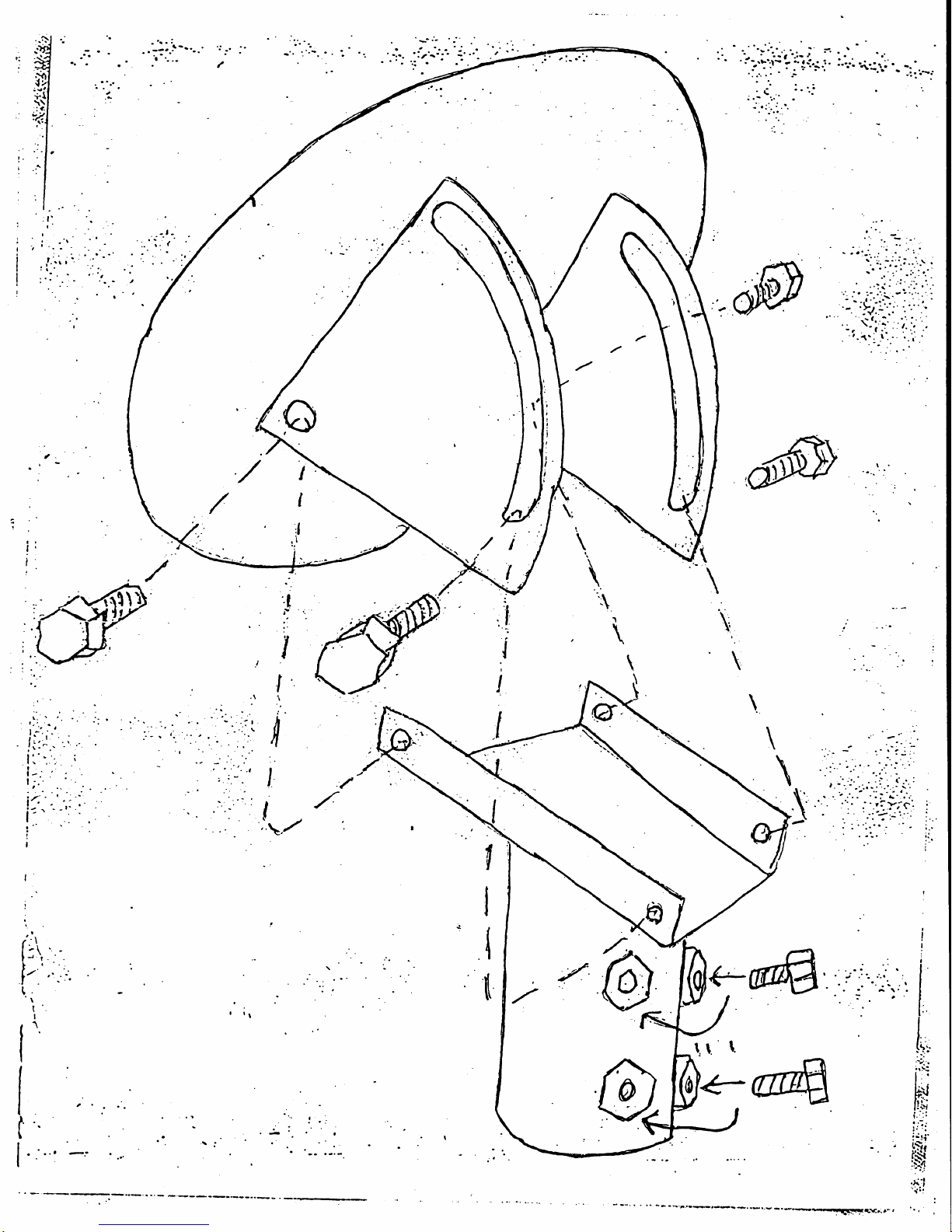
STEP
THREE:
Assemble
the
anterna
f@
(bwn
m a llat
surface.
Place
pre-assembled
mount
on
mount
pipe,
and attacfi anterna b nqrtei
sfxnn h
pholc.
t
t,'/
cautlon: cable runs oyer 150 feet
may requlre
ampllfiers
to boost rlgnalto
recelver.
SOT,|E
MOI'NTS PIVOTOFF
CENTER
FOR BETTER AIMING RESOLUTION.
MOUNT
ACTUATOR
oN TH|S
SIDE
double
rlbs ltt lnto
and are bolted
to
cllps
use flat washers
md tlghten
until
cllps
bavc out
bofts
In holes trsed to
fr*fi
ddr b
mount rlng
usc bofts llat resficrl
nd
to asscnrUe
CAUTION: DO
NOT
OYERTGHTEN
BOLTS
STEP FOUR:
Feed
slstem assec$ly
arrd
acljusfinent b nextMeasure tocal lengffi
frqn
center d
frorrt
date
b
1/4 lncfl
inside
lee<l
opening.
CAUTIOiI: Do nd
torrcfl
probe
inside
feed
rttach
Uacr(
plss$c
leed
cover
mounting
plab
to bolb fier legs
are
ettacfied
to !eed, focal
lcng0t
ls
rct and
nuts
ere tght.
Ure
fia
rasher
end econd nut
to
fasten
set F/D ratio
on feed
follow
instructions
provlded
by feed
manufacturer
DISH
SZE FOCAL
LENGTH
F/D
RATIO
12
FOOT
s7 5E INCHES
.sB
10
FOOT
4s
5/8
INCHES
.38
z.s
FOOT
33
U4 INCHES
.37s
6 FOOT
26
l|4INCHES
.3zs
assemble
Ged
ryatem
ettach to leed
legs
Include base
tor fecd
cover
ret focal
length
maaturc
ftom
center
of front
plate
to 1/4'
Inelde
lced
opcnlng
adlurt
lbcd
to
elm rt
contcr
ol rcflcc{or
rcrsnble dish
lace
down
on
fiat
surface
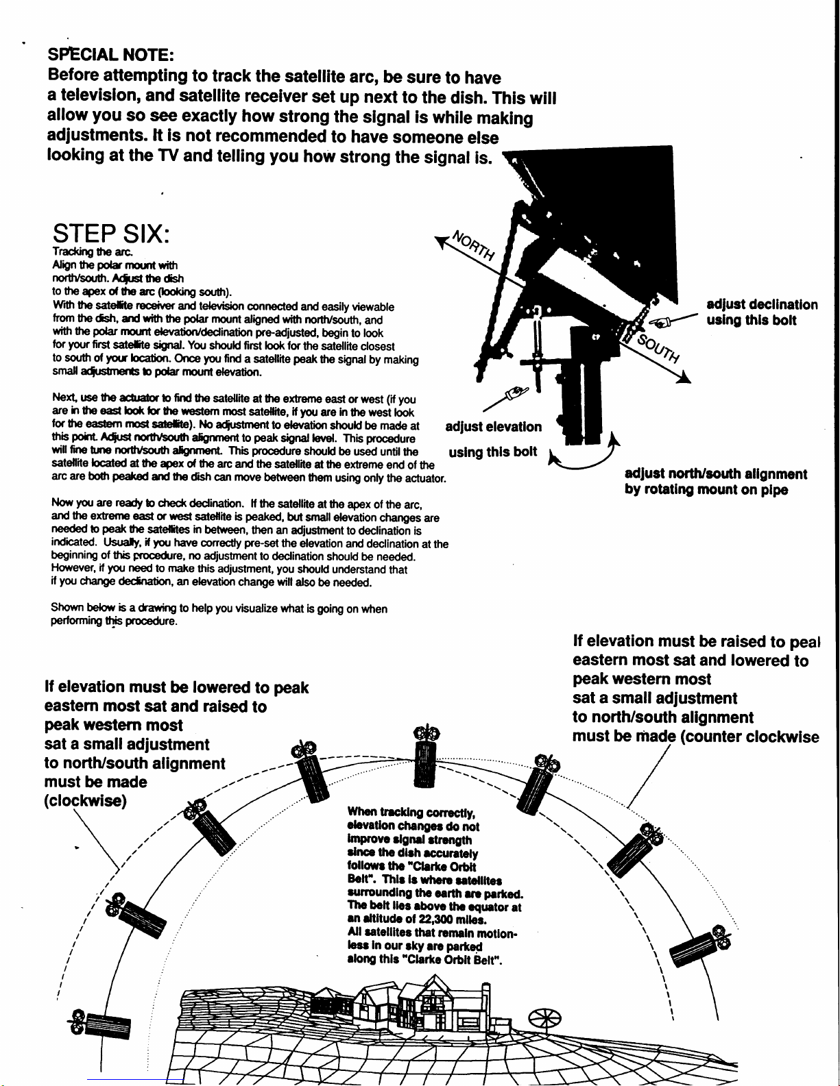
SPECIAL
NOTE:
Before
attempting
to
track
the
satellite
arc,
be
sure
to
have
a
televislon,
and
satellite
receiver
set
up next
to
the
dish.
This
will
allow
you
so
see
exactly
how
strong
the
slgnal is
while
making
adjustments.
lt
is not
recommended
to have
somEone
else
looking
at
the
TV
and
telling
you
how
strong
the
signal
is.
STEP
SIX:
Tracklrg
the arc"
AIgn
tte
potar
flnmtwi0l
northlsorffr.
A6rst
|ho
dsh
to the
+x
o{
the arc
(lookFg
soufr).
wrth
the
sdefie
receiver
and televtf<m
connected
and
easily viewable
from
the dsh
ad
wi0t
the
polar
rrount
aligned wi0r
north/south,
and
with
the
polar
ru.mt
de{/atiorvdedination
preadjusted,
begin
to
look
for
your
firsil
sderte
*rral.
You
strould first
look for
the satellile
closest
to
soutr
of
yotr
bcatbn.
once
you
find
a satellile
peak
the signal
by making
smaff
a{stnerfs
b
pdar
rTtount
elevation.
l.lext
use the
dfrr
b
find
the
satellite
at the
exteme
east or west
(il you
are
h
tE
east bor
hr the restem
most
satellite, il
you
are in
the
west
look
lor
the
€rrilem
rnst
s&tte). tlo
a6strnent
to devation
should be made
at
adfust
rtb
poirt
A4rsn
norfibor.dfr
argrment
to
peak
signal levsl.
This
procedure
wi[ fins
trp
norhlsouor
argrmeril. Thb
procedure
shor,rld be
used untilthe
uslng
satellite
locded
d ute
Ter
of the
arc and the
satellite
at he
extrsme
end
of the
arc are
boft
pe*od
and tte
dslr
can
ntove
betrreen
them
using
only the
actuator.
Now
yott
are
redry
b
chec*
dedination.
lf
tre
satellite
at the
apex
of the
arc,
and rte
e,fieflE
east
or
resil
sdeflile
b
peakecl,
hrt
smallelevation
changes
are
needed
b
peak
tte
satef,tes in
betrveen,
then an
adjustment
to
declination is
indcated.
l.tsuafy,
il
you
have
conecdy
pre-set
the
elevation
and declination
at the
beginnirB
of tris
Frooedure,
rrc
adiustnent
to
dedination
should
be
needed.
Flowever,
if
you
need
to
make
this adjustment,
you
should understand
that
if
yor
cfiange
declnatim,
an elevation
charge willalso
be needed.
Shown befrf,
b a
fawirB
to
help
you
visualize
wtrat
is
going
on when
perfonning
thb
procedlre.
lf
elevation
must
be
lowered
to
peak
eastern
most
sat and raised
to
peak
western
most
sat a small
adjustment
to north/south
alignment
must
be made
(clockwise)
lVhor
tncklng
conecdy,
cbvatlon
changgr
do
mt
lmprovc
rlgnel
drcng[h
dnce
lhe
dlrh
rccuntdy
lollowr
thc'C1srtc
Orbtl
Eolt'.
Thb
lr
whctr
retcllller
nrmundlng
tho
cailh
rn
peiled.
Thc
bolt lles
abow
thc
cqrntor
at
an
ellltude
of 22,300
mller.
Allt8tellltes
thst
aemrln
moilon.
hcr In
our
rky
arc
parted
rlong
lhls'Clalte
Orblt
Belt'.
.g
elevatlon
thls
bolt
adfust
decllnatlon
uslng
thls
bolt
adlust north/south
allgnment
by
rotating
mount
on
plpe
lf
elevation
must
be
raised
to
peat
eastern
most
sat and
lowered
to
peak
westem
most
sat a
small
adjustment
to north/south
alignment
must
be fiade
(counter
clockwise
{
\
\
\
\
\!
\
\
I
I
I
I
I
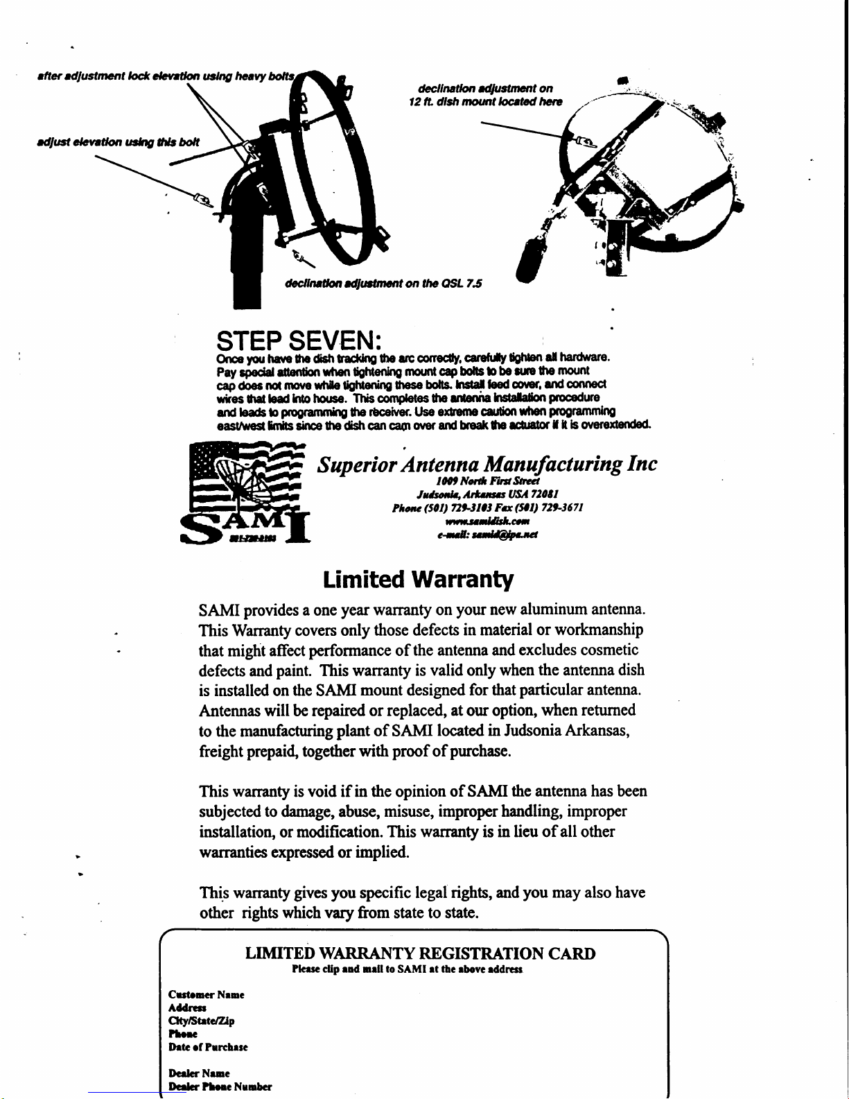
drf,ter odlustment ld
*yttba
.Bt
V
havy
dfi.6t c/r,wdott t*rg
A{s
Dolt
&lhttdot rdltffirlctrt on the OSiL
75
STEP
SEVEN:
On€
pu
lrart tho d.Eh Sactktg
the rrc conecily.
cat€frfy
fdtbn
a! hadware.
Pay
epedd
dention
wtt o tgtilettftg
flnlnt cap bolts
b
be 3uE
lhe
mount
capdoes
nd
npve wfiIe$ilening
tl1oso
bolt3.
hstat leedgprer.
and
connecf
wiies
|h.l
lod
Into lsrso.
-nrF
oomptetes ho ltilertita
hilala[on
procedure
and loa6 b
Fryaflmhg
ho
rbcelvef. use
oOerne caldon
lhm
ptogramfiilng
oast/unstffiSs
sltu ho dbh cil
caot
over and btgaft$o
rctator
f
I b onrenended
Superior
Antenna
Maryafacturing
Inc
IOO| Nor*
ndSM
,r',lffiltLtu,
rr*nsl&Itais
c*lil:n&tu
Limited
Warranty
SAMI
provides a
one
year
warranty on
your
new
aluminum antenna.
This Warranty
covers
only
those defects
in material
or workmanship
that
might affect
performance
of the
antenna and excludes
cosmetic
defects
and
paint.
This warranty
is valid only
when
the
antenna
dish
is installed on
the
SAIvII
mount
designed
for that
particular
antenna.
Antennas
will be repaired
or replaced,
at
our option,
when returned
to the manufacturing
plant
of SAMI
located in
Judsonia
Arkansas,
freight
prepai4
together with
proof
of
purchase.
This
warranty
is void if in the opinion
of
SAI{I
the antenna has been
subjected to danrage, abuse,
misuse, improper handling,
improper
installation,
or
modification. This
warranty
is in
lieu of all
other
warranties expressed
or
implied.
This warranty
gives
you
specific legal
rights, and
you
may also
have
other
rights which vary from
state
to state.
LIMITED WARRANTY
REGISTRATION
CARI)
Plcrsc clip end
nell to SAMI rt
thc
rbevc
rddrrrs
Crrtrucr !{ruc
Addrtrr
Oty/StltcZlp
?torc
lhtc rf Prrchrrc
Ilcrlcr
Neuc
Dc.lcr
?lcre Nrnbcr
&,Lrttlotr
tdtustmant on
12lL dlslt
,tpunt torrltgd ,E
e
/
| ,l
,\
t
I
-{
'tt
1,
1.
1.
 Loading...