

Superior WXS2021WS Installation And Operation Manual
INSTALLATION AND OPERATION MANUAL
Free-Standing
EPA Certified
Wood-Burning Stoves
Save These Instructions
For Future Reference
P/N 900109-01, Rev. NC, 12/2013
P900109-01
A French manual is available upon request. Order P/N 900189-01.
Ce manuel d’installation est disponible en francais, simplement en faire la demande. Numéro de la
pièce 900189-01.
Report # 100854192PRT-001
Wood-Burning Stove
Model WXS2021WS
This appliance must be properly installed and operated in order to prevent the pos-
sibility of a house fire. Please read this entire installation and operation manual
before installing and using your wood stove. Failure to follow these instruc-
tions could result in property damage, bodily injury or even death. Contact
your local building or fire officials to obtain a permit and information
on any installation requirements and inspection requirements
in your area.
WARNING
• Hot! Do not touch! The glass and surfaces of this appliance will
be hot during operation and will retain heat for a while after
shutting off the appliance. Severe burns may result.
• Carefully supervise children in the same room as appliance.

CONGRATULATIONS!
When you purchased your new wood stove, you joined the ranks of
thousands of individuals whose answer to their home heating needs
reflects their concern for aesthetics, efficiency and our environment. We
extend our continued support to help you achieve the maximum benefit
and enjoyment available from your new wood stove.
Thank you for selecting an
as the answer to your home supplemental heating needs.
TABLE OF CONTENTS
Using This Manual ......................................................................... 2
Important Safety Information ......................................................... 3
Testing Information ........................................................................ 4
Draft Requirements ........................................................................ 4
Selecting the Proper Venting System ............................................. 4
Negative Pressure Warning ........................................................... 5
Clearances to Combustibles ........................................................ 6-7
Floor Protection ............................................................................. 6
Chimney and Connector ................................................................. 6
Components .................................................................................. 6
Installation Clearances ................................................................... 7
Specifications ................................................................................ 8
Typical Installation Figures ............................................................. 9
Innovative Hearth Products, LLC (IHP) Stove
Chimney Installation .................................................................... 10
Manufactured (mobile) Home Installations .................................. 10
Chimney - Wall Pass-Through Requirements .............................. 11
Outside Combustion Air Kit Installation ....................................... 12
Brick Installation .......................................................................... 13
Post Installation Checks ............................................................... 14
Paint Curing ................................................................................. 15
Burn-In Period ............................................................................. 15
Operating Hints ............................................................................ 15
Door Operation ........................................................................... 15
Starting and Maintaining a Fire .................................................... 16
Fuel ......................................................................................... 17
Getting the Most Out of Your Stove .............................................18
Maximizing Your Stove’s Overall Efficiency .................................. 18
Achieving Clean, Long Burns ....................................................... 18
Optional Blower Kit ..................................................................... 19
Do’s and Don’ts ...........................................................................20
Maintenance ................................................................................ 20
Creosote ....................................................................................... 21
Troubleshooting ........................................................................... 22
Replacement Parts Lists .............................................................. 23
Accessories .................................................................................. 24
Safety / Listing Labels .................................................................. 25
Warranty ...................................................................................... 27
Product Reference Information .................................................... 28
USING THIS MANUAL
Please read and carefully follow all of the instructions found in this
manual. Please pay special attention to the safety instructions provided
in this manual.
PRODUCT IS SUBJECT TO CHANGE WITHOUT NOTICE
2

IMPORTANT SAFETY AND WARNING
INFORMATION
READ THIS MANUAL IN ITS ENTIRETY AND UNDERSTAND THESE RULES TO FOLLOW FOR SAFETY.
1. When this room heater is not properly installed, a house
fire may result. To reduce the risk of fire, follow the installation instructions. Contact local building or fire officials
about restrictions and installation inspection requirements
in your area.
2. Wear gloves during installation to avoid injury from sharp
edges on the stove and/or its parts.
3. This unit is designed and engineered to burn only dry, wellseasoned wood. Burning wet wood will greatly reduce the
stove’s efficiency, produce excessive amounts of smoke
and can cause dangerous chimney fires due to creosote
build-up.
4. Before opening the door, the draft control must be fully open
to avoid possible combustion flash (ignition of hot volatile
gases as the door is opened).
5. Never use gasoline, gasoline-type lantern fuel, kerosene,
charcoal lighter fluid, or similar liquids to start or ’freshenup’
a fire in this heater. Keep all such liquids well away from
the heater while it is in use. DO NOT USE CHEMICALS OR
FLUIDS TO START THE FIRE.
6. While burning, fuel utilizes oxygen from the air in the room.
Be sure to allow an adequate amount of fresh air into the
room where the stove is burning.
7. The outside surface of the stove will be hot while burning
properly and can set items like clothing and curtains on
fire. Keep furnishings and other combustible materials
away from the stove. Using the heat from the stove to dry
wet clothing can be hazardous if clothes are placed too
near the surface of the stove.
8. HOT WHILE IN OPERATION. KEEP CHILDREN, CLOTHING
FURNISHINGS AND COMBUSTIBLE MATERIAL A CONSIDERABLE DISTANCE AWAY. CONTACT MAY CAUSE SKIN BURNS.
Do not allow children to play near the stove without close
supervision. Do not touch the stove while it is burning.
Use extreme caution while the unit is in use. Surface temperatures become dangerously hot and can cause serious
burns.
9. Do not allow anyone to operate the stove who is not familiar
with the operating instructions.
10. Attempts to achieve heat output rates that exceed stove
design specifications can result in permanent damage to
the stove. Never leave your stove unattended on high burn
rates. This may cause overfiring. Overfiring the stove may
cause a house fire. If the stove glows, you are overfiring.
11. Keep a water hose or hand-operated fire extinguisher close
for safety.
12. Smoke Detectors - Since there are always several potential sources of fire in any home, we recommend installing
smoke detectors. If possible, install the smoke detector in
a hallway adjacent to the room (to reduce the possibility
of occasional false activation from the heat produced by
the stove). If your local code requires a smoke detector
be installed within the same room, you must follow the
requirements of your local code. Check with your local
building department for requirements in your area.
13. Inspect your chimney at least once a month during the burn-
ing season to check for soot and creosote accumulations.
Any accumulations over 1/8” thick should be removed by
a professional chimney sweep. Do not attempt to burn out
heavy creosote accumulations with a hot fire. If large accumulations are occurring, review your burning procedures.
14. If a creosote fire should develop, the fire department should
be called immediately and then attempts should be made
to control the fire until assistance arrives. If a “runaway”
fire should develop causing over-heating of the stove, the
door and draft regulators should be closed immediately.
The fire should die down once deprived of oxygen. After a
severe chimney fire, the complete chimney system should
be checked before further use.
15. Do Not Use Grate Or Elevate Fire - Build Wood Fire Directly
On Hearth (firebrick). Do not use andirons or other methods
of supporting the fuel.
16. Please read this entire manual before you install and use
your new room heater. Failure to follow instructions may
result in property damage, bodily injury, or even death.
17. Check all local building and safety codes before installation.
The installation instructions and appropriate code requirements must be followed exactly and without compromise.
In the absence of local codes the following standards and
codes must be followed.
18. In the U.S.A, install in accordance with the National Fire
Protection Association’s Code, NFPA 211, Standards for
Chimneys, Fireplaces, Vents and Solid-Fuel-Burning Appliances, or similar regulations, may apply to the installation
of a Solid-Fuel-Burning appliance in your area. In Canada,
the guideline is established by the CSA Standard, CAN/
CSA-B365-M93, Installation Code for Solid-Fuel-Burning
Appliances and Equipment.
19. DO NOT CONNECT TO OR USE IN CONJUNCTION WITH ANY
AIR DISTRIBUTION DUCTWORK UNLESS SPECIFICALLY
APPROVED FOR SUCH INSTALLATIONS.
20. WARNING: BURNING IMPROPER FUEL (I.E. CHARCOAL)
CAN RESULT IN CARBON MONOXIDE POISONING, WHICH
MAY LEAD TO DEATH!
21. Carbon Monoxide Poisoning – Early signs of carbon monoxide poisoning resemble the flu with headaches, dizziness,
or nausea. If you have these signs, get fresh air at once!
Have the heater inspected by a qualified service technician.
Some people are more affected by carbon monoxide than
others. These include pregnant women, people with heart
or lung disease or anemia, those under the influence of
alcohol, and those at high altitudes.
22. Failure to use manufacturer provided parts, variations in
techniques and construction materials or practices other than
those described in this manual may create a fire hazard and
void the limited warranty.
23. Do not make any make-shift compromises during installation. Any modification or alteration may result in damage
to the appliance or dwelling and will void the warranty,
certification and listings of this unit.
24. These appliances are designed as supplemental heaters.
Therefore, it is advisable to have an alternate heat source
when installed in a dwelling.
25. Do Not Overfire – If Heater or Chimney Connector Glows,
You Are Overfiring.
26. DO NOT CONNECT THIS UNIT TO A CHIMNEY FLUE SERVING ANOTHER APPLIANCE.
27. DO NOT BURN GARBAGE OR FLAMMABLE FLUIDS SUCH
AS GASOLINE, NAPHTHA OR ENGINE OIL.
3

TESTING INFORMATION
SELECTING THE PROPER VENTING SYSTEM
This manual describes the installation and operation of these non-catalytic
wood heaters. These heaters meet the U.S. Environmental Protection
Agency’s emissions limits for wood heaters sold on or after July 1, 1990.
This heater has been developed, tested and constructed in accordance
with the requirements of UL 1482-2010, ULC S627-00 and HUD standards
and is listed by Intertek, Portland, OR. It has been approved for residential
and mobile home installations.
DRAFT REQUIREMENTS
This appliance is dependent upon a properly functioning chimney for
optimum performance. It is a high efficiency appliance that loses much
less heat up the chimney than older appliances and fireplaces. For this
reason it is important to match the stove to the chimney. The chimney
has two functions:
1. It draws combustion air into the appliance (without air, no fuel will
burn) and
2. It exhausts combustion by-products. Your new appliance is what is
known as a “natural draft” appliance.
The appliance depends solely on the natural draft of the chimney system
to draw combustion air into the unit. Draft is the force that moves air from
the appliance up into the chimney. The amount of draft in your chimney
depends on the length of the chimney, local geography, nearby obstructions
and other factors. Too much draft may cause excessive temperatures in
the appliance (overfiring). Slow or inadequate draft equals poor combustion and possible smoking problems. The following are some conditions
that may contribute to poor chimney draft:
1. A chimney too large for your appliance.
2. A chimney with not enough height to produce adequate draft.
3. A chimney with excessive height (this may allow exhaust to cool too
much before exiting, which will stall the rate the exhaust exits).
4. Offsets in the venting system are too restrictive (see Chimney Guide-
lines).
Inadequate draft will cause the appliance to leak smoke into the room
through the stove and the chimney connector joints.
Excessive draft may cause an uncontrollable burn or a glowing red stove
or chimney part.
Overfiring Damage - If the heater or chimney connector glows, you are
overfiring. Other symptoms may include: Cracking, warping or burning
out of components, stove glass may develop a haze, which will not come
off with cleaning.
The appliance is merely one component of a larger system. The other
equally important component is the venting system. This is necessary for
achieving the required flow of combustion air to the fire chamber and for
safely removing unwanted combustion by-products from the appliance.
If the venting system’s design does not promote these ends, the system
may not function properly. Poorly functioning venting systems may create
performance problems as well as be a safety hazard. A draft test should
read greater than .04’ W.C. (inches water column) and less than .08”
W.C . As per NFPA-211 standard (see paragraph below), the installer
must take into account all variables within the installation and install the
appliance in such a manner that satisfies the draft requirements of the
appliance. See Chimney Guidelines below to assist you in selecting the
proper venting system for your installation.
American National Standards Institute ANSI/NFPA 211, Standard for
Chimneys, Fireplaces, Vents, and Solid Fuel-Burning Appliances - See
Draft Section: A chimney or vent shall be so designed and constructed
to develop a flow sufficient to completely remove all flue and vent gases
to the outside atmosphere. The venting system shall satisfy the draft
requirements of the connected appliance in accordance with the manufacturer’s instructions.
Chimney Guidelines:
• Thisappliancerequiresapproximately12feetminimumof“effective
draw” provided by the venting system. As a rule of thumb, every 90
degree total direction change in the venting will result in a loss of
approximately 5 feet of “effective draw.” Example: If two 45 degree
offsets are used, subtract 5 feet from the actual vertical vent height
to determine your “effective draw.” In this case if you had 14 feet of
vertical vent, the effective draw would only be approximately 9 feet
(14 ft. - 5 ft. = 9 ft.), therefore it may be necessary to add additional
height to the venting system.
• Donotinstallanoffsetwithinthersttwofeetabovetheueoutlet
on the appliance.
• Inwellinsulatedandweathertighthomes,itmaybedifculttoestablish a good draft up your chimney. The poor draft is caused by a
shortage of air in the house. In this situation an Outside Air Kit may
need to be installed (See Negative Pressure Warning on Page 5 and
Outside Combustion Air on Page 12).
Overfiring of a stove is a condition where excessive temperatures are
reached, beyond the design capabilities of the appliance. The damage
that occurs from overfiring is not covered under the manufacturer’s
limited warranty.
Also see Troubleshooting on Page 22.
4
NOTE: DIAGRAMS & ILLUSTRATIONS ARE NOT TO SCALE.
Less than
10' (3 m)
10'
(3 m)
3' (914 mm)
Min.
2’ (610 mm) Min.
(914 mm)
Min.
3'
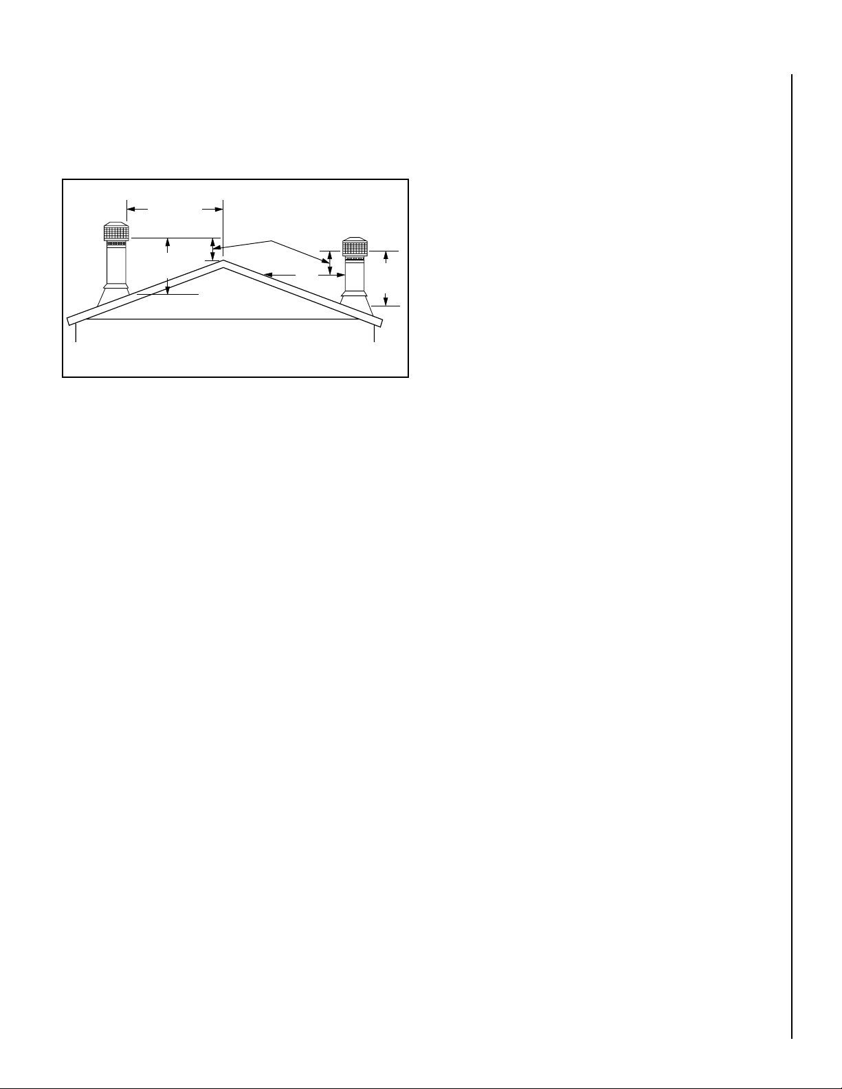
Chimney Height Requirements
NEGATIVE PRESSURE WARNING
The chimney must extend 3’ (.92m) above the level of roof penetration
and a minimum of 2’ (.61m) higher than any roof surface within 10’ (3m)
(see Figure 1). Check with your local building officials for additional
requirements for your area.
Figure 1 - Chimney Height Requirements
To pass inspection in nearly any jurisdiction, the chimney must meet both
safety and exhaust flow requirements. The (3’ by) 2’ by 10’ rule applies
to both masonry and factory-built chimneys.
* Ref. USA - National Standard, NFPA 211-latest edition and Canada
National Standard CSA B365-01-latest edition. Vents installed with a
listed cap shall terminate in accordance with the terms of the cap’s
listings.
This appliance is not designed to be operated in a negative pressure.
In very airtight homes with large kitchen exhaust fans, furnace cold air
returns, fresh air exchange systems and any other air system in close
proximity to the heating appliance may create a negative pressure in
the same room as the heating appliance. This can create dangerous
back drafting of the stove and chimney joints, drawing combustion byproducts into the home. Be sure your home has adequate makeup air to
eliminate negative pressures caused by the above-mentioned sources.
Outside air connected to the appliance probably will not resolve such
a problem as the stove or fireplace insert is not the source of negative
pressure. IHP accepts no liability for damages resulting from negative
pressures described here.
Ventilation Requirements - Provide adequate air for combustion. The
fresh air requirements of this appliance must be met within the space
where it will be installed. Ventilation is essential when using a Solid-FuelBurning heater. In well insulated and weather tight homes, it may be
difficult to establish a good draft up the chimney (caused by a shortage
of air in the home). The lack of air is caused by many common household
appliances which exhaust air from the home (such as a furnace, heat
pump, air conditioner, clothes dryer, exhaust fans, fireplaces, and other
fuel burning appliances). Also, the combustion process of this heater
uses oxygen from inside the dwelling. If the available fresh air delivery
in the dwelling is insufficient to support the demands of these appliances,
problems can result (i.e. excessive negative pressure can develop in the
dwelling which will affect the rate at which this appliance can draft thus
resulting in performance problems. To correct this problem it may help
to open a window (preferably on the windward side of the house) or
install an optional outside air kit.
NOTE: DIAGRAMS & ILLUSTRATIONS ARE NOT TO SCALE.
5

CLEARANCES TO COMBUSTIBLES
CHIMNEY AND CONNECTOR
WARNING: BE ABSOLUTELY SURE THE DISTANCE BETWEEN THE
HEATER AND THE SURFACE OF ANY COMBUSTIBLE CONSTRUCTION IS NOT LESS THAN SHOWN IN THE FIGURES ON PAGE 7.
Floor Protection
USA - The floor in front and under the heater must be protected with
noncombustible material. The covering must extend 16” in front of the
door opening of the heater and 8” to either side of the door opening.
Canada - The floor in front and under the heater must be protected with
noncombustible material. The covering must extend 450 mm in front of
the door opening of the heater and 200 mm to either side of the stove
body and 200 mm to the rear or to the wall, whichever is smaller.
USA and Canada - A chimney connector / venting extends horizontally
over the floor, protection must also cover the floor under the connector
/ venting and at least 2” (51 mm) to either side.
Minimum 6" diameter, minimum 24 MSG black steel connector pipe with
UL103HT listed factory-built chimney suitable for use with solid fuels
or masonry chimney. Horizontal connection not tested, refer to local
building codes for installation. See installation instructions for details.
Restrictions apply! Read instructions before installing.
Residential chimney systems must be from the same brands as listed
for mobile homes but connector pipe may be double wall, single wall or
single wall with shield as listed above.
This appliance may be vented into a code-approved masonry chimney
with flue liner.
WARNING: CHIMNEY CONNECTOR MUST BE IN GOOD CONDITION AND
KEPT CLEAN. DO NOT INSTALL DAMAGED PARTS.
All of the stove connector pipe used must be of the same brand. The
chimney that the stove pipe transitions into may be a different brand.
Other than the transition of the stove pipe into the chimney, do Not mix
different brand vent components. Install all vent components per vent
manufacturer’s instructions.
The chimney connector shall not pass through an attic or roof space,
closet or similar concealed space, or a floor, or ceiling. Where passage
through a wall, or partition of combustible construction is desired, the
installation shall conform to CAN/CSA-B365, Installation Code for SolidFuel-Burning Appliances and Equipment.
There must be an effective vapor barrier at the location where the chimney
or other component penetrates to the exterior of the structure. Follow the
vent manufacturer's detailed instructions.
IMPORTANT NOTE: See Draft Requirements and Selecting a Proper
Venting System on Page 4 to assist you in choosing the proper venting
system for your installation.
Clearance dimensions are to flue collar. If a single wall connector pipe
with shield is used, a 1 inch air space is needed between pipe and shield.
Shield attaches to rear of stove pipe and must run from stove top to ceiling. Pipe shield shall be UL listed.
6
NOTE: DIAGRAMS & ILLUSTRATIONS ARE NOT TO SCALE.
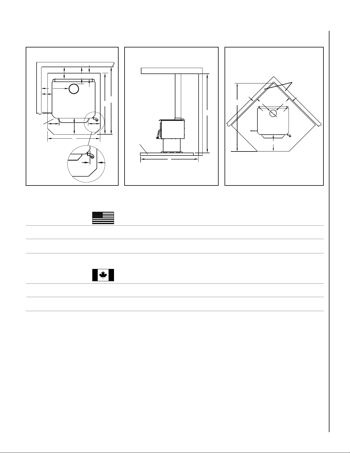
INSTALLATION CLEARANCES - REFER TO FIGURES 2, 3 AND 4
Parallel Installation
Parallel Installation
Corner Installation
Combustible Wall
B
A
L
C
D
USA
Stove
Canada
USA
E
E
E
K
J
See note 8
Combustible Wall
Floor
Protection
Top View
Figure 2
USA
- inches (millimeters)
PIPE INSTALLATION A (3) B (1) C (3) D (1) E (8) F (1) G (3) H (2) I (6) J (2) K (7) L (5) M T (6)
Single Wall Residential
(362) (292) (584) (340) (200) (229) (457) (956) (1245) (886) (406) (0) (2134) (1562)
Double Wall Residential or Mobile Home
(305) (232) (495) (245) (200) (152) (381) (956) (1188) (886) (406) (0) (2134) (1461)
14-1/4 11-1/2 23
I
H
Floor
Protection
Figure 3
12 9-1/8 19-1/2
T
M
G
F
Stove
I
Side View
Top View
Figure 4
13-3/8
8 9 18 37-5/8 49 34-7/8 16 0 84 61-1/2
9-5/8
8 6 15 37-5/8 46-3/4 34-7/8 16 0 84 57-1/2
6” Ø Flue
Collar
Stove
K
Combustible
Wall
G
F
Floor
Protection
CANADA
PIPE INSTALLATION A (3) B (1) C (3) D (1) E (8) F (1) G (3) H (2) I (6) J (2) K (7) L (5) M T (6)
Single Wall Residential
(362) (292) (584) (
Double Wall Residential or Mobile Home
(305) (232) (495) (
Footnotes:
1- These dimensions to the stove body are for reference
2- Minimum noncombustible hearth pad dimensions.
3- Clearances to connector pipe shall be measured from
- inches (millimeters)
14-1/4 11-1/2 23
12 9-1/8 19-1/2
only. Actual distances should be measured from the
stove’s flue collar.
the flue collar of the stove.
13-3/8
8 9 18 47-5/8 51 40-7/8 18 8 84 63-1/2
340)
(200) (229) (457) (1210) (1295) (1038) (450) (200) (2134) (1613)
9-5/8
8 6 15 47-5/8 48-3/4 40-7/8 18 8 84 59-1/2
245
) (200) (152) (381) (1210) (1238) (1038) (450) (200) (2134) (1511)
5- In corner applications, when installed at minimum
back wall clearances, the required floor protection
is dimensioned off the back plane of the stove,
therefore the floor protection required off the
back corners (at a 45 degree angle) only needs
to extend to the wall. This situation will only occur
in CANADA installations.
NOTE: DIAGRAMS & ILLUSTRATIONS ARE NOT TO SCALE.
6- Reference dimension only, to assist in planning
the installation.
7- Measured from front of floor protection to the
front of firebox.
8- USA=8” (200mm) from door opening, Canada=8”
(200mm) from sides and back of unit.
7
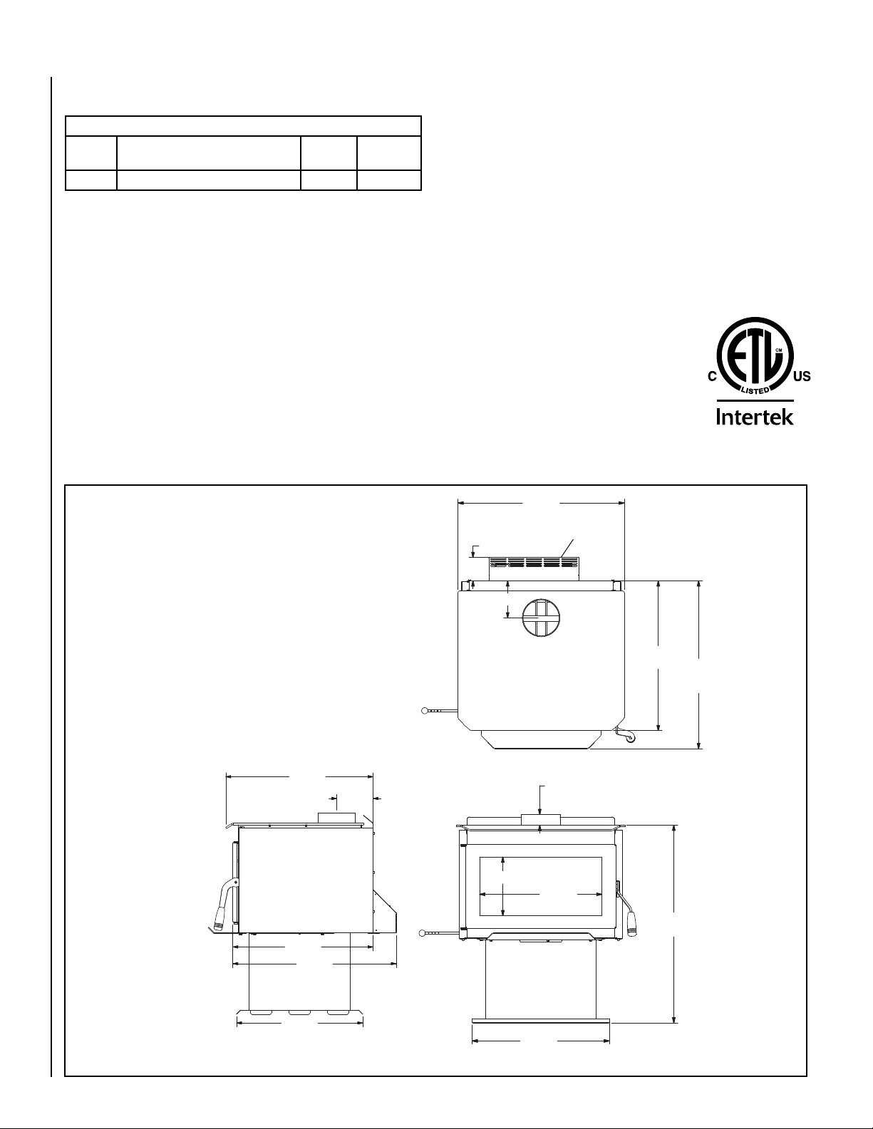
SPECIFICATIONS - WXS2021WS
Stove Pipe Diameter
Single Wall or Double Wall 6” (152 mm)
Product Reference Information
Cat. No. Description Ship.
Weight
F1775 WXS2021WS Wood-Burning Stove 310 lb. 23 cu. ft.
Ship.
Volume
NOTES:
• Dimensions shown are approximations only (+/- 1/4”)
• Diagrams, illustrations and photographs are not to scale – consult installa-
tion instructions. Product designs, materials, dimensions, specifications,
colors and prices are subject to change or discontinuance without notice.
• Approved for residential and manufactured home installations.
• Optional Kits Available:
Blower
Outside Air Kit
Square-foot heating capacities and burn times are approximations only.
u
Actual performance may vary depending upon home design and insulation, ceiling heights, climate, condition and type of wood used, appliance
location, burn rate, accessories chosen, chimney installation and how the
appliance is operated.
Log Length 20” Max. (508 mm Max.)
Firebox Volume = 2.1 cu. ft.
Cord Wood: u 76,000 BTUs/hr.
Maximum Burn Times u 7-9 hours
Heating Capacity u 1,200 to 2,000 sq. ft.
Specifications
EPA Grams Per Hour 3.0 gr/hr
EPA Phase II and Washington State Approved
The WXS2021WS woodstove is safety
listed with the following agency:
• Intertek, Tested to UL 1482, ULC S627
Listing
25-7/8”
(657mm)
3-11/16” (94mm)
Optional Blower
4002589
Dimensions
23-3/8”
(584mm)
22-1/4”
(565mm)
25-7/8”
(657mm)
5-3/4”
(146mm)
5-3/4” (146mm)
9” (229mm)
TOP VIEW
1-5/8” (41mm)
18-3/4”
(476mm)
23-3/8”
(594mm)
30-5/16”
(770mm)
26-3/16”
(665mm)
Figure 5
20”
(508mm)
RIGHT SIDE VIEW
21”
(533mm)
FRONT VIEW
8
NOTE: DIAGRAMS & ILLUSTRATIONS ARE NOT TO SCALE.
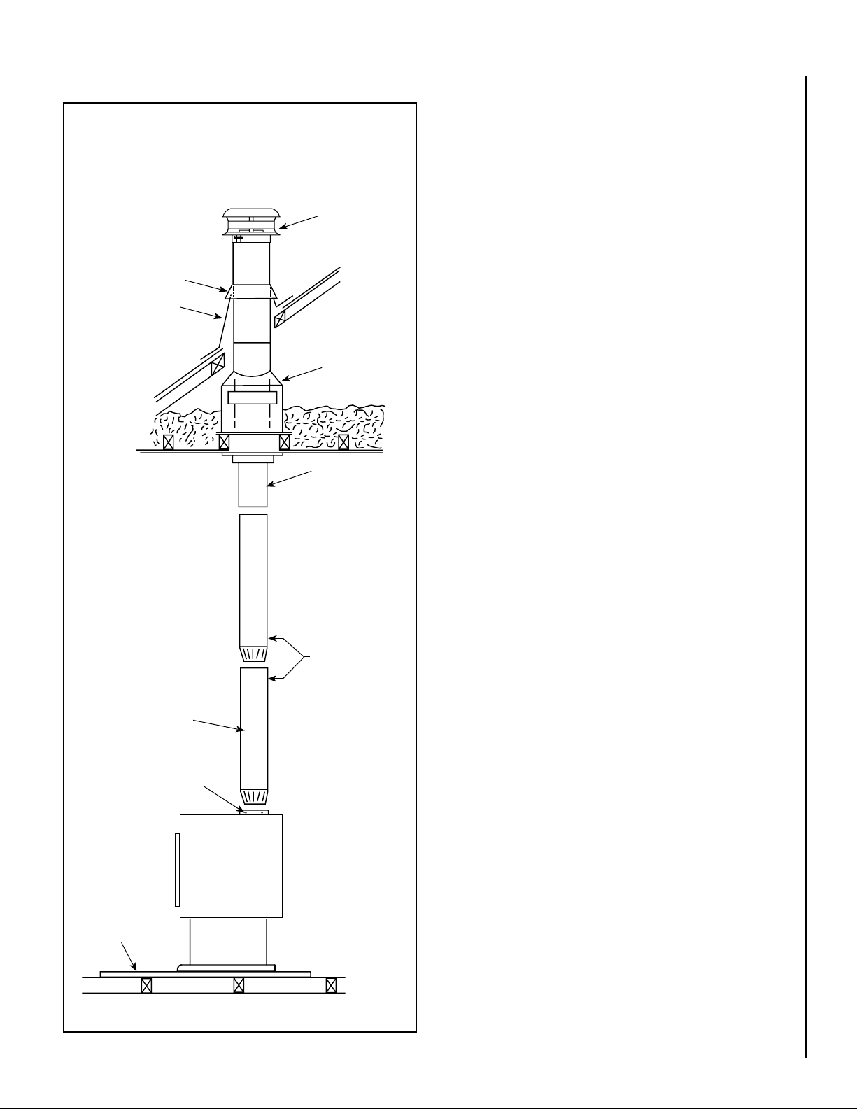
TYPICAL INSTALLATIONS
Single Wall Pipe
Using 6” Diameter Single Wall Connector Pipe
INSTALL VENTING SYSTEM PER VENT MANUFACTURERS
INSTRUCTIONS!
Chimney
Termination
Cap
Storm
Collar
Roof
Flashing
Ceiling Support
Assembly
Slip
Adaptor
YOUR CHIMNEY INSTALLATION MUST COMPLY WITH LOCAL
BUILDING AND FIRE CODES.
Single wall stove pipe
must not pass through
attics, closets, walls or
ceilings. It is used to
connect this appliance
to a factory built or
masonry chimney.
Fasten each stove pipe
connection with at least
3 sheet metal screws.
6” x 24” 24-gage
black steel or 26
gage blued steel
single wall pipe
Fasten stove pipe to
flue collar with 3 sheet
metal screws.
Floor
Protector
Chimney
Connector
Stove
Side View
Figure 6 - Typical Installation
9
NOTE: DIAGRAMS & ILLUSTRATIONS ARE NOT TO SCALE.
 Loading...