

Superior WRT6036RS, WRT6036IS, WRT6036RH, WRT6036IH, WRT6042RS Installation And Operation Instructions Manual
...
Installation and Operation Instructions
PFS
Superior™ Indoor Wood Burning Fireplace
P/N 126595-01 Rev. A 01/2014
P126595-01
Models
®
USC
WRT6036RS
WRT6036IS
WRT6036RH
WRT6036IH
WRT6042RS
WRT6042IS
WRT6042RH
WRT6042IH
WRT6050RS
WRT6050IS
WRT6050RH
WRT6050IH
SAVE THIS BOOK
This book is valuable. In addition to instructing you on how to install and maintain your appliance, it also contains
information that will enable you to obtain replacement parts or accessory items when needed. Keep it with your other
important papers.
INSTALLER: Leave this manual with the appliance.
CONSUMER: Retain this manual for future reference.
This wood burning fireplace complies with
UL127 CAN/ULC-S610-M87 standard as a
FACTORY BUILT FIREPLACE.
This fireplace is approved for use as a wood burning fireplace or for use with a vented gas log approved to
ANSI Z21.60 or Z21.84 standards or for use with a vent-free gas log heater approved to ANSI Z21.11.2 standard.
FOR CANADA: The authority having jurisdiction
(such as the municipal building department, fire
department, etc.) should be contacted before
installation to determine the need to obtain a
permit.
Installateur : Laissez cette notice avec l’appareil.
Consommateur : Conservez cette notice pour consultation ultérieure.
Ce foyer au bois est conforme aux UL 127 CAN/ULCS610-M87 norme comme une USINE CONSTRUITE
CHEMINÉE.
POUR LE CANADA: L’autorité compétente (comme le
service municipal du bâtiment, les pompiers, etc.) doit
être contacté avant l’installation afin de déterminer la
nécessité d’obtenir un permis.
This appliance may be installed in an aftermarket permanently located, manufactured home (USA only)
or mobile home, where not prohibited by local codes. This appliance is only for use with the type of gas indicated
on the rating plate. This appliance is not convertible for use with other gases, unless a certified kit is used.
WARNING: If the information in these
instructions is not followed exactly, a fire or
explosion may result causing property damage,
personal injury or death.
— Do not store or use gasoline or other
flammable vapors and liquids in the vicinity
of this or any other appliance.
— WHAT TO DO IF YOU SMELL GAS:
• Do not try to light any appliance.
• Do not touch any electrical switch; do not
use any phone in your building.
• Immediately call your gas supplier from
a neighbor’s phone. Follow the gas
supplier’s instructions.
• If you cannot reach your gas supplier, call
the fire department.
— Installation and service must be performed
by a qualified installer, service agency or the
gas supplier.
AVERTISSEMENT : Assurez-vous de bien suivre les
instructions données dans cette notice pour réduire au
minimum le risque d’incindie ou d’explosion ou pour éviter
tout dommage matériel, toute blessure ou la mort.
— Ne pas entreposer ni utilizer d’essence ni d’autres
vapeurs ou liquides inflammables dans le voisinage
de cet appareil ou de tout autre appareil.
— QUE FAIRE SI VOUS SENTEZ UNE ODEUR DE GAZ :
• Ne pas tenter d’allumer d’appareil.
• Ne touchez à aucan interrupteur. Ne pas vous
servir des téléphones se trouvant dans le bâtiment
où vous trouvez.
• Appelez immédiatement votre fournisseur de
gaz depuis un voisin. Suivez les instructions du
fournisseur.
• Si vous ne pouvez rejoindre le fournisseur de gaz,
appelez le service des incindies.
— L’installation et l’entretien doivent être assurés par un
installateur ou un service d’entretien qualifié ou par
le fournisseur de gaz.
www.SuperiorFireplaces.US.com
126595-01A2
WARNING: Improper installation, adjustment, altera-
tion, service or maintenance can cause injury, property
damage or loss of life. Refer to this manual for assis-
tance or additional information. Consult a qualied
installer or local distributor.
TABLE OF CONTENTS
Safety .................................................................. 2
Specications ...................................................... 3
Fireplace Installation............................................ 6
Venting Installation .............................................. 8
Firebrick Wall Installation ................................... 13
Optional Gas Line Installation............................ 16
Glass Door Installation ...................................... 17
Operation and Maintenance Guidelines ............ 18
Parts ................................................................. 20
Technical Service............................................... 27
Replacement Parts ............................................ 27
Accessories ....................................................... 28
SAFETY
FOR YOUR SAFETY
• Do not store or use gasoline
or any other ammable vapors
or liquids in the vicinity of this
or any other appliance.
• Due to high temperatures, the
appliance should be located
out of trafc and away from
furniture and draperies.
• Do not place clothing or other
ammable materials on or near
the appliance.
• Never leave children unattended when a re is burning
in the replace.
WARNING: Use solid wood
or processed solid fuel relogs
only. When processed wood fuel
re logs are used, do not poke or
stir the logs while they are burning. Use only re logs that have
been evaluated for the application
in replace and refer to re log
warnings and caution markings
on packaging prior to use.
This replace is not intended to be
used as a substitute for a furnace
to heat an entire home. Use for
supplemental heat only.
IMPORTANT: Check local codes
before installing this replace.
Before beginning the installation of the
fireplace, read these instructions through
completely.
• This INNOVATIVE HEARTH PRODUCTS
fireplace and its components are safe
when installed according to this installation
manual. Unless you use IHP components,
which have been designed and tested for
the replace system, you may cause a re
hazard.
• The INNOVATIVE HEARTH PRODUCTS
warranty will be voided by and IHP disclaims any responsibility for the following
actions.
a. Modification of the fireplace, com-
ponents, doors, air inlet system and
damper control.
b. Use of any component part not manu-
factured or approved by INNOVATIVE
HEARTH PRODUCTS in combination
with a IHP replace system.
Proper installation is the most important step
in ensuring safe and continuous operation
of the replace. Consult the local building
codes as to the particular requirements
concerned with the installation of all factory
built replaces.
WARNING: Do not install a
replace insert in this box unless
the manufacturer's instructions
with the insert specically state
this replace has been tested for
use with this insert.
www.SuperiorFireplaces.US.com
126595-01A 3
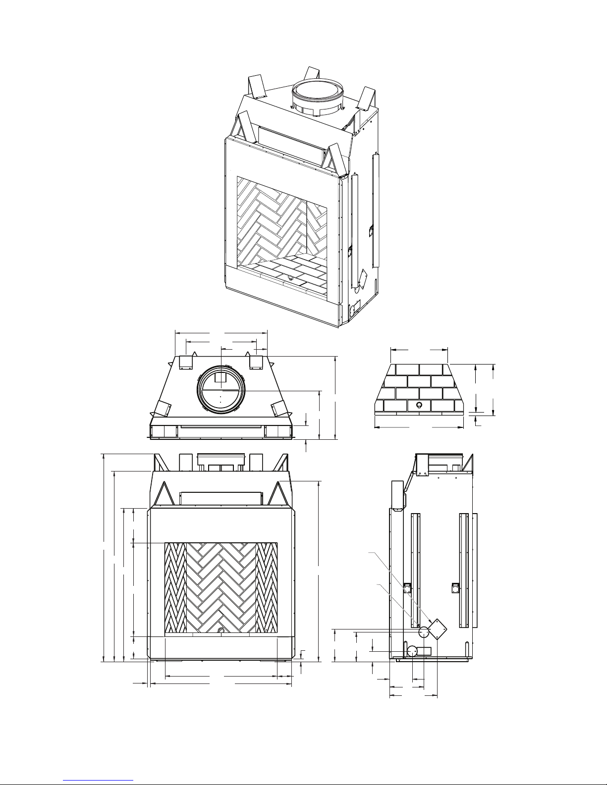
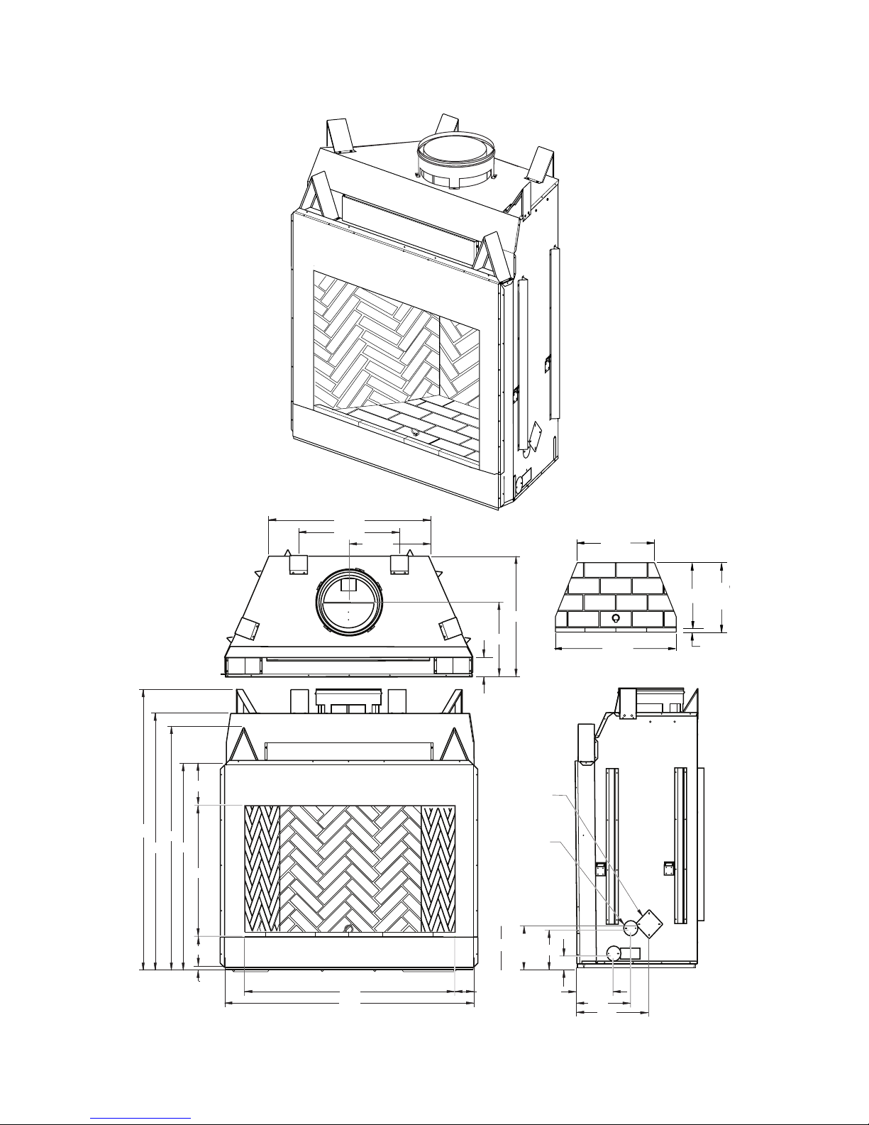
SPECIFICATIONS
36" MODELS
29"
14 1/2"
22 1/2"
26 5/8"
4 1/2"
15 5/8"
4 1/2"
1"
58"
7 1/4"
11"
15 1/4"
3 1/2"
9 1/2"
10 1/2"
67"
61"
49"
11"
7"
30"
1"
45
1
/8"
36"
OUTSIDE AIR
ACCESS
GAS LINE
ACCESS
36" HEARTH
1
1
/4"
20
1
/4"
(Ref.)
35
1
/4"
19"
22 1/2"
Figure 1 - 36" Models WRT6036RS, WRT6036IS, WRT6036RH and WRT6036IH
www.SuperiorFireplaces.US.com
126595-01A4
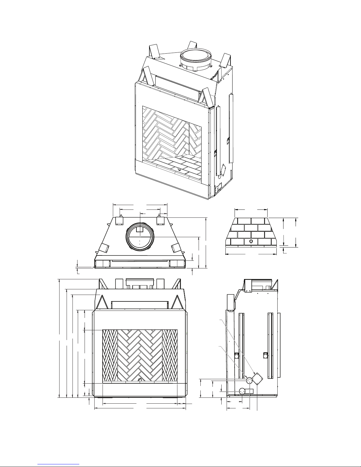
SPECIFICATIONS Continued
42" MODELS
22 3/4"
30 1/2"
29"
4 3/8"
15 3/4"
5/8"
17 5/8"
67"
61"
49"
7"
1"
30"
11"
58"
42"
51 1/8"
4 1/2"
3 1/2"
9 1/2"
10 1/2"
81/2"
13"
OUTSIDE
AIR
ACCESS
GAS LINE
ACCESS
42" HEARTH
1
1
/4"
23"
(Ref.)
41
3
/8"
26 3/8"
21
3
/4"
Figure 2 - 42" Models WRT6042RS, WRT6042IS, WRT6042RH and WRT6042IH
www.SuperiorFireplaces.US.com
126595-01A 5
SPECIFICATIONS Continued
50" MODELS
38 1/2"
28 1/2"
43/8"
17 5/8"
19 1/4"
24"
49"
30"
11"
61"
67"
58"
7"
1"
59"
50"
4 1/2"
3 1/2"
9 1/2"
10 1/2"
8 1/2"
13"
17"
GAS LINE
ACCESS
OUTSIDE
AIR
ACCESS
50" HEARTH
1
1
/4"
23"
(Ref.)
49 3/8"
34 3/8"
21
3
/4"
Figure 3 - 50" Models WRT6050RS, WRT6050IS, WRT6050RH and WRT6050IH
www.SuperiorFireplaces.US.com
126595-01A6
FIREPLACE INSTALLATION
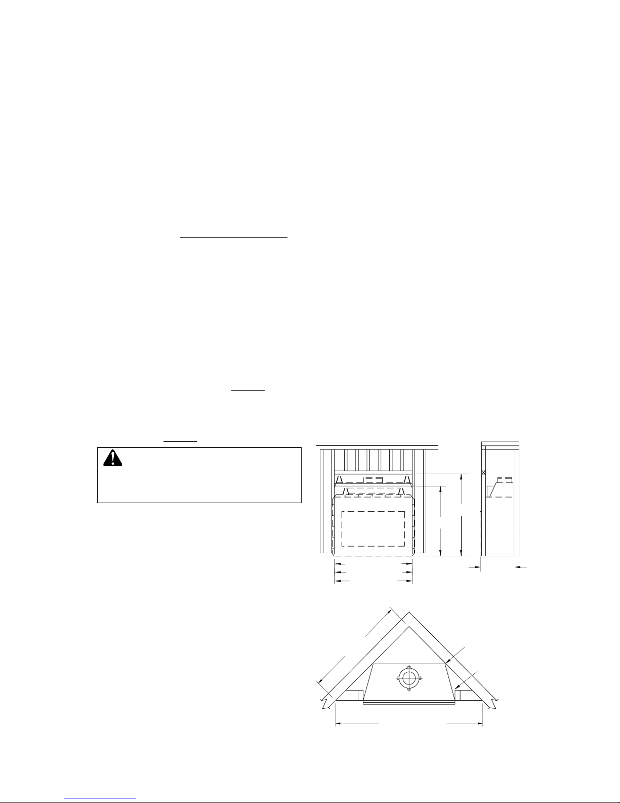
FRAMING
1. Frame opening for replace using dimensions shown in Figures 4 and 5.
2. If replace is to be installed directly on
carpeting, tile (other than ceramic) or any
combustible material other than wood
ooring, replace must be installed upon
a metal or wood panel extending full width
and depth of replace.
3. Set replace directly in front of this opening and slide unit back until nailing anges
touch side framing.
4. Check level of the replace and shim with
sheet metal if necessary.
5. Before securing fireplace to prepared
framing, ember protector (provided) must
be placed between hearth extension (not
supplied) and under bottom front edge of
replace to protect against glowing embers
falling through. If replace is to be installed
on a raised platform, a Z-type ember protector (not supplied) must be fabricated to
t your required platform height. Ember
protector should extend under replace a
minimum of 1 1/2". Ember protector should
be made of galvanized sheet metal (28
gauge minimum to prevent corrosion.
6. Using screws or nails, secure replace to
framing through anges located on sides
of replace.
30.125"
59" (50" Models)
58.125"
67.125"
51.25" (42" Models)
45.25" (36" Models)
28.250" (36" Models)
Figure 4 - Framing Dimensions
71" (50" Models)
100" (50" Models)
65" (42" Models)
92" (42" Models)
86.5" (36" Models)
61" (36" Models)
Maintain 1
1
/2"
Clearance
at Sides and
Back of Fireplace
1
1
/2" Clearance
Not Required at
Nailing Flanges
Figure 5 - Corner Installation
SELECTING LOCATION
To determine the safest and most efcient
location for the replace, you must take into
consideration the following guidelines:
1. The location must allow for proper clearances (see Figures 4 and 5).
2. Consider a location where replace will
not be affected by drafts, air conditioning
ducts, windows or doors.
3. A location that avoids cutting of joists or
roof rafters will make installation easier.
4. An outside air kit is available with this
replace (see Optional Outside Air Kit on
page 8).
MINIMUM CLEARANCE TO
COMBUSTIBLES
Back and sides of replace 1 1/2" m i n .
Ceiling 42" min.
Front of replace 48" min.
Floor** 0" min.
Perpendicular wall to opening 18" min.
36" Models 12" min.
Top spacers 0" min.
Mantel clearances
see Mantels, page 7
Chimney outer pipe surface 2" min.
36" Model 1" min.
* Not required at nailing anges
** See step 2 of Framing
WARNING: Do not pack re-
quired air spaces with insulation
or other materials.
Minimum/Maximum Chimney Height for
Residential Installation
Minimum height of chimney, measured from
base of replace to ue gas outlet of termination, is 16 feet for straight ue or a ue with
one elbow set. Maximum distance between
elbows is 6 feet. For systems with two elbow
sets, minimum height is 22 feet. Maximum
height of any system is 50 feet. This measurement includes replace, chimney sections and
height of termination assembly at level of the
ue gas outlet (see Figure 15, page 11).
www.SuperiorFireplaces.US.com
126595-01A 7
Note: For outdoor installations, fireplace
enclosure must allow for adequate drainage
and fresh air ventilation. It is recommended
that a sealed, corrosion resistant catch pan
with provision for drainage be installed under
replace within replace enclosure.
HEARTH EXTENSION
A hearth extension projecting a minimum of
20" in front of and a minimum of 12" beyond
each side of replace opening is required to
protect combustible oor construction in front
of replace. Fabricate a hearth extension
using a material which meets the following
specications: a layer of noncombustible,
inorganic material having a thermal conductivity of K=0.84 BTU IN/FT, HR. F (or less) at
1" thick. For example, if the material selected
has a K factor of 0.25, such as glass ber, the
following formula would apply:
0.25 x 1.0" = 0.30" thickness required
0.84
Thermal conductivity "K" of materials can be
obtained from manufacturer or supplier of
noncombustible material. If hearth extension
is to be covered, use noncombustible material such as tile, slate, brick, concrete, metal,
glass, marble, stone, etc. Provide a means
to prevent hearth extension from shifting and
seal gap between replace frame and hearth
extension with a noncombustible material
(see Figure 6).
WARNING: Hearth extension
is to be installed only as shown
in Figure 6.
FIREPLACE INSTALLATION
Continued
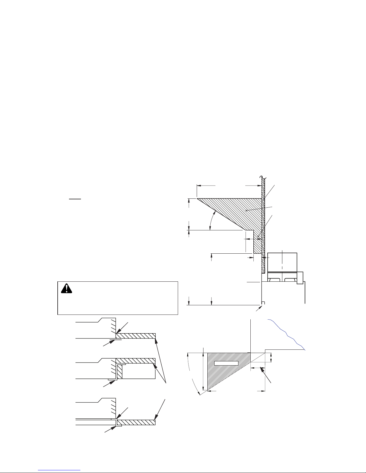
Figure 6 - Hearth Extension
Seal Gap
Fireplace Front
Ember Protector
Fireplace Front
Raised Hearth
Fireplace Front
Elevated
Ember Protector
Ember Protector
Seal Gap
Hearth
Extension
MANTELS
A mantel may be installed if desired (see Figure
7). Woodwork such as wood trims, mantels or
any other combustible material projecting from
front face must not be placed within 12" (36"
Models) or 18" (42/50" Models) of replace
opening. Combustible materials above 12" (36"
Models) or 18" (42/50" Models) and projecting
more than 1 1/2" from replace must not be
placed less than 15" (36" Models) or 21" (42/50"
Models) from the top opening of the replace
(NFPA STD 211, Sec. 7-3.3.3).
Mantels or any other combustible material
also may come up to side edge of black metal
face of replace as long as projections from
front face fall within limit shown in Figure 7.
12 1/4" Ref.
6"
Ref.
15" Min. (36" Models)
21" Min. (42/50"
Models)
12" Min.
(36" Models)
18" Min.
(42/50"
Models)
11/2" Max.
3" Nom.
33°
Combustible
Material
Safe
Zone for
Projection of
Combustible
Materials
Fireplace Opening
Upper
Section of
Fireplace
Figure 7 - Mantel Clearances to
Combustible Material
FIREBOX
SAFE ZONE
Top View of Fireplace
3" Max.
4.5"
Min. to
Perpendicular
Side Wall
7.75" (36" Models)
11.5" (42/50" Models)
33°
Combustible
Material Must
Not Overlap
Front Face
12" - 36" Models
18" - 42/50" Models
www.SuperiorFireplaces.US.com
126595-01A8
Figure 9 - Lineal Gain
LINEAL GAIN
PART NO. DESCRIPTION GAIN
Signature Fireplace 66 1/2"
12-12DM
12-12HT
Pipe Section 10 5/8"
18-12DM
18-12HT
Pipe Section 16 5/8"
24-12DM
24-12HT
Pipe Section 23 5/8"
36-12DM
36-12HT
Pipe Section 34 5/8"
48-12DM
48-12HT
Pipe Section 46 5/8"
RLT-12D
RLT-12HT
Round Termination 7 3/4"
*
STL-12D
Square Chase-Top
with Slip Section
7" to 15"*
* The lineal gain for the terminations is measured to the ue gas outlet height.
Hemmed
End
12 3/8"
Stainless
Inner Pipe
15" Galvanized
Outer Pipe
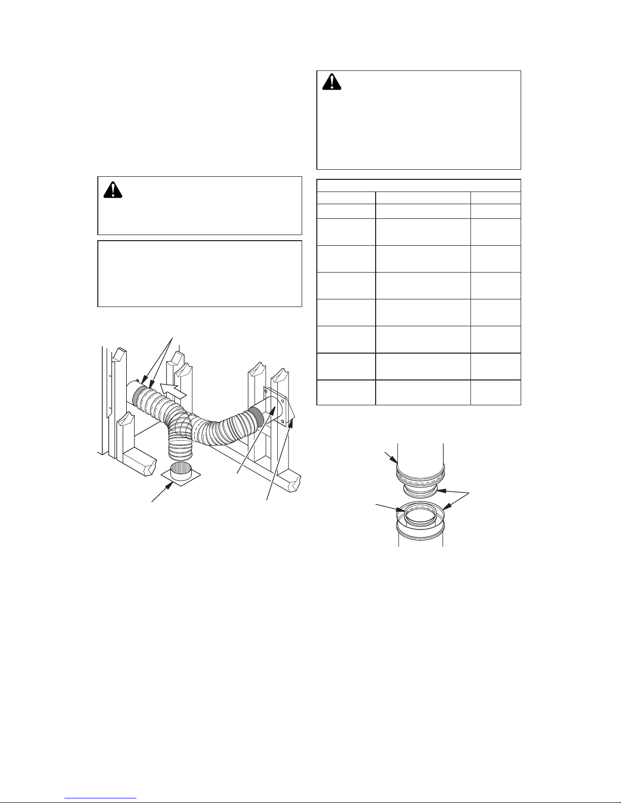
ASSEMBLY AND INSTALLATION OF
DOUBLE WALL CHIMNEY SYSTEM
Each double wall chimney section consists of a
galvanized outer pipe, a stainless steel inner ue
pipe and a wire spacer. The pipe sections must
be assembled independently as the chimney is
installed. When connecting chimney directly to
the replace, the inner ue pipe section must
be installed rst with the lanced side up. The
outer pipe section can then be installed over
5 the ue pipe section with the hemmed end
up. Press down on each pipe section until the
lances securely engage the hem on the replace
starter. The wire will assure the proper spacing
between the inner and outer pipe sections.
Figure 8 - Outside Air Kit
Secure to Collars with Metal Tape,
Screws or Straps (Min. of 1/4" x 20"
in size)
Air Inlet
Location
Must Allow
For Bushes
or Snow
Vent Hood
Required for
Wall Installation
Air Inlet
Eyebrow
Vented Crawl Space
(Check Local Codes
Before Installing in a
Vented Crawl Space)
CHIMNEY PIPE
The INNOVATIVE HEARTH PRODUCTS
chimney system consists of 12", 18", 24",
36" and 48" snap-lock, double-wall pipe segments, planned for maximum adaptability to
individual site requirements. Actual lengths
gained after tting overlaps must be taken
into consideration (lineal gain) and are given
in the lineal gain chart (see Figure 9). Lineal
Gain is the actual measurable length of a part
after two or more parts are connected. For
Canada, use chimney parts designated "HT".
VENTING INSTALLATION
OPTIONAL OUTSIDE AIR KIT
(MODEL AK4/AK4F)
The installation of an outside air kit should
be performed during the rough framing of
the replace due to the nature of it's location.
Outside combustion air is accessed through
a vented crawl space (AK4F) or through a
sidewall (AK4).
CAUTION: Combustion air
inlet ducts shall not terminate
in attic space.
The maximum height for the
air vent can not exceed 3 feet
below the ue gas outlet of the
termination.
WARNING: The opening in
the collar around the chimney at
the top of the replace must not
be obstructed. Never use blown
insulation to ll the chimney
enclosure.
www.SuperiorFireplaces.US.com
126595-01A 9
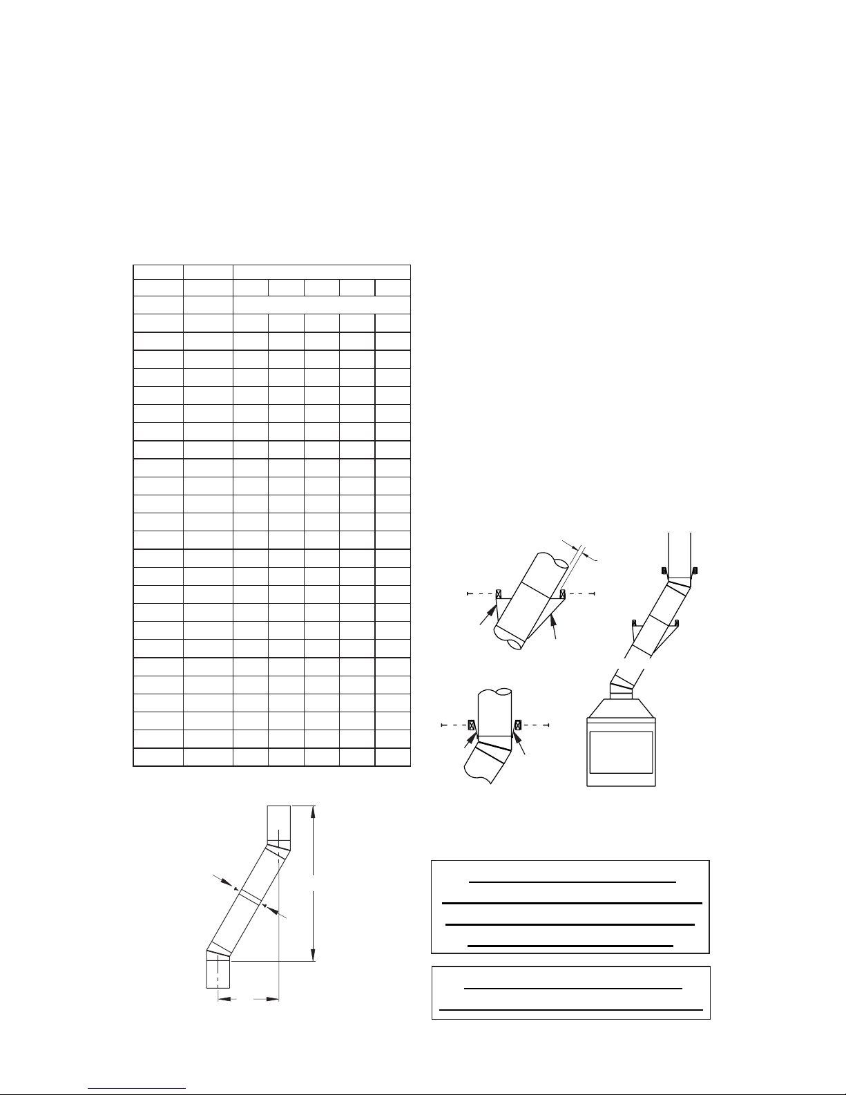
VENTING INSTALLATION
Continued
OFFSET
RISE CHIMNEY LENGTH
A B 12" 18" 24" 36" 48"
4 3/8" 16 3/8"
ELBOW SET ONLY
9 3/4" 25 1/2"
1
12 3/4" 30 3/4"
1
15" 34 3/4"
1
18" 40"
1 1
21 1/4" 46 1/4"
1
23 3/4" 49 1/4"
1 1
27 3/4" 56 3/4"
1
30" 60 3/4"
1 1
33" 66"
1
36" 71"
1 1
38 1/4" 75"
2
41 1/4" 80 1/4"
1 1 1
45" 86 3/4"
2
46 3/4" 89 1/2"
1 1 1
51" 97"
1 1
53 1/4" 101"
2
56 1/4" 106 1/4"
2
59 1/4" 111 1/2"
1 1 1
61 3/4" 115 1/2"
1 2
64 3/4" 120 3/4"
1 2
68 1/4" 127"
2 1
70" 130"
1 1 2
74 1/4" 137 1/2"
1 2 1
76 3/4" 141 1/2"
1 2 1
79 3/4" 146 3/4"
4
OFFSET CHART (22-50 FT. SYSTEM HEIGHT)
Figure 11 - Ceiling Support Pipe
12S-12DM
2" Min.
Straps
Straps
Straps
Straps
Detail A
Return Elbow
Detail B
Angle Firestop
See Detail A
See Detail B
Continue to assemble chimney sections as
outlined above, making sure that both the
inner and outer pipe sections are locked together. When installing double wall snap-lock
chimney together, it is important to assure
the joint between the chimney sections is
locked. Check by pulling chimney upward
after locking. The chimney will not come apart
Figure 10 - Elbow Offset
B
A
Screws
if properly locked. It is not necessary to add
screws to keep the chimney together (exception, see Figure 10).
USING ELBOW OFFSETS (30E-12DM)
1.
To achieve desired offset, you may install
combinations of 12", 18", 24", 36" and 48"
length of double wall pipe (see offset chart
and Figure 10).
2.
Chimney weight above offset rests on
return elbow. Straps must be securely
nailed to rafters or joists (see Figure 11,
details A and B).
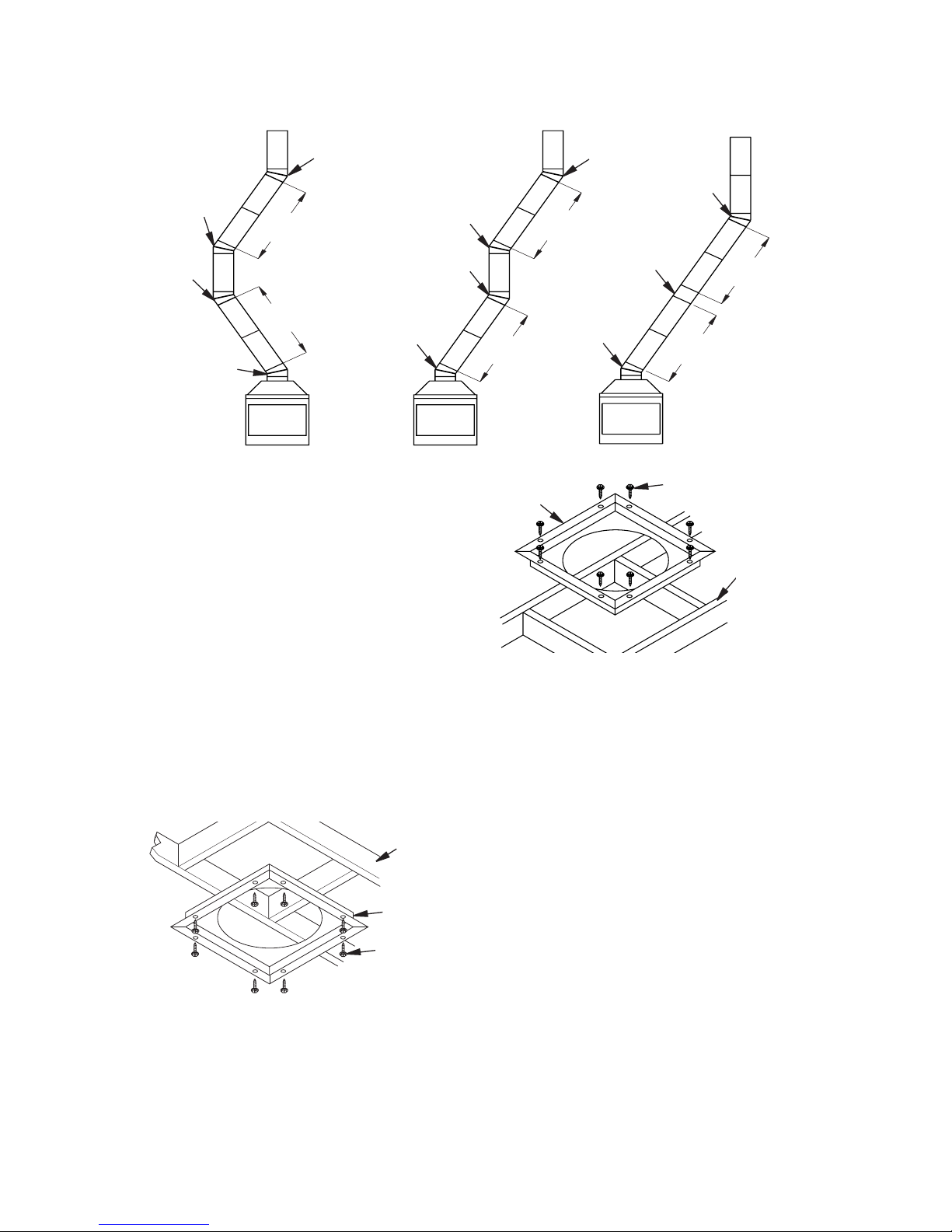
3. Maximum length of pipe between supports (return elbow or 12S-12DM) is 6'
of angle run. Maximum of two 6' angle
run sections per chimney system (see
Figure 12, page 10).
4. All pipe connections between the offset
and return must be secured with two
screws on the outer pipe only (see
Figure 10). Do not penetrate the inner
stainless.
CAUTION: THE STRUCTURAL
INTEGRITY OF THE MANUFACTURED
HOME FLOOR, WALL, AND CEILING/
ROOF MUST BE MAINTAINED.
WARNING: DO NOT INSTALL IN
SLEEPING ROOM OF MOBILE HOMES.
www.SuperiorFireplaces.US.com
126595-01A10
VENTING INSTALLATION
Continued
FIRESTOP SPACERS (FS-10,
1100EFS-10DM FOR 36" MODELS)
Firestop spacers are required at each point
where the chimney penetrates a oor space.
Their purpose is to establish and maintain
the required clearance between the chimney
and the combustible materials. When the pipe
passes through a framed opening into a living
space above, the restop must be placed onto
the ceiling from below as shown in Figure 13.
They also provide complete separation from
one oor space to another or attic space as
required by most codes. When the double wall
pipe passes through a framed opening into an
attic space, the restop must be placed into an
attic oor as shown in Figure 14.
Figure 13 - Firestop Spacer with Living
Space Above Ceiling
Figure 14 - Firestop Spacer with Attic
Space Above Ceiling
Existing
Ceiling
Frame
Firestop
Spacer
Screws or
Staples
(Min. of 8)
Firestop
Spacer
Screws or Staples
(Min. of 8)
PENETRATING ROOF
To maintain a 1" (36" Models) or 2" (42/50"
Models) clearance to the pipe on a roof with a
pitch, a rectangular opening must be cut.
1. Determine center point through which pipe
will penetrate roof.
2. Determine center point of roof. Pitch is
distance the roof drops over a given span,
usually 12". A 6/12 pitch means that roof
drops 6" for each 12" measured horizontally down from roof rafters.
3. Use roof opening chart (Figure 15, page
11) to determine correct opening length
and ashing required.
4. Remove shingles around opening measured. Cut out this section.
Existing
Ceiling
Frame
Figure 12 - Typical Offset Terminations
Return
Elbow
Offset
Elbow
Return
Elbow
Offset
Elbow
6' Max.
6' Max.
6' Max.
6' Max.
6' Max.
6' Max.
Return
Elbow
Offset
Elbow
Offset
Elbow
Return
Elbow
A B C
Offset
Elbow
Ceiling
Support Pipe
12S-12DM
Return
Elbow
 Loading...