

Page 1
DANGER
PFS
®
USC
P/N 127035-01 Rev. C 04/2015
Installation and Operation Instructions
Superior™ Stainless Outdoor Linear
Fireplace
Models
P127035-01
INSTALLER: Leave this manual with the appliance.
CONSUMER: Retain this manual for future reference.
REPORT NO. F12-052
VRE4543EN
Installateur : Laissez cette notice avec l’appareil.
Consommateur : Conservez cette notice pour consultation ultérieure.
VRE4543EP
WHEN USED AS AN OUTDOOR APPLIANCE
CARBON MONOXIDE WARNING
• This appliance can produce
carbon monoxide which has
no odor.
• Using it in an enclosed
space can kill you.
• Never use this appliance in
an enclosed space such as
a camper, tent, car or home.
WARNING: Do not store gasoline or other flammable vapors and liquids in the vicinity of this or any
other appliance. An LP-cylinder not connected for use shall not be stored in the vicinity of this or any other
appliance.
WARNING: For Outdoor Use Only.
DANGER
IF YOU SMELL GAS:
1. Shut off gas to appliance.
2. Extinguish any open flame.
3. If odor continues, keep away from the appliance and immediately call your gas supplier
or fire department.
WARNING: Improper installation, adjustment, alteration, service or maintenance can cause injury or
property damage. Read the installation, operating and maintenance instructions thoroughly before installing or servicing this equipment.
WARNING: If the information in these
instructions is not followed exactly, a fire or
explosion may result causing property damage,
personal injury or death.
— Do not store or use gasoline or other
flammable vapors and liquids in the vicinity
of this or any other appliance.
— WHAT TO DO IF YOU SMELL GAS:
• Do not try to light any appliance.
• Do not touch any electrical switch; do not
use any phone in your building.
• Immediately call your gas supplier from
a neighbor’s phone. Follow the gas
supplier’s instructions.
• If you cannot reach your gas supplier, call
the fire department.
— Installation and service must be performed
by a qualified installer, service agency or the
gas supplier.
AVERTISSEMENT : Assurez-vous de bien suivre les
instructions données dans cette notice pour réduire au
minimum le risque d’incindie ou d’explosion ou pour éviter
tout dommage matériel, toute blessure ou la mort.
— Ne pas entreposer ni utilizer d’essence ni d’autres
vapeurs ou liquides inflammables dans le voisinage
de cet appareil ou de tout autre appareil.
— QUE FAIRE SI VOUS SENTEZ UNE ODEUR DE GAZ :
• Ne pas tenter d’allumer d’appareil.
• Ne touchez à aucan interrupteur. Ne pas vous
servir des téléphones se trouvant dans le bâtiment
où vous trouvez.
• Appelez immédiatement votre fournisseur de
gaz depuis un voisin. Suivez les instructions du
fournisseur.
• Si vous ne pouvez rejoindre le fournisseur de gaz,
appelez le service des incindies.
— L’installation et l’entretien doivent être assurés par un
installateur ou un service d’entretien qualifié ou par le
fournisseur de gaz.
Page 2
Thank you for your purchase. We appreciate your
business!
Please carefully read and follow all instructions in this manual. Pay
special attention to all warnings and safety information.
Following these safety, care, and operation instructions will help
ensure many years of dependable and enjoyable service from your
fireplace.
Register your product online today!
To help us keep you up-to-date on product information and offers, please take a few moments to register your product online
at Superiorfireplaces.US.com (Owner Resources/Product Reg-
istration).
Please read and understand these instructions before installing
or operating.
TABLE OF CONTENTS
Safety ............................................................................................. 2
Local Codes ................................................................................... 3
Requirements for the Commonwealth of Massachusetts............... 3
Product Identification ..................................................................... 4
Product Features ............................................................................ 4
Installation ..................................................................................... 4
Operation .................................................................................... 14
Cleaning and Maintenance .......................................................... 15
Inspecting Burners ...................................................................... 15
Replacing Light Bulbs .................................................................. 15
Wiring Diagram ............................................................................ 16
Troubleshooting ........................................................................... 17
Parts ............................................................................................ 20
Specifications ............................................................................... 23
Service Hints ................................................................................ 23
Technical Service ......................................................................... 23
Replacement Parts ....................................................................... 23
Accessories .................................................................................. 23
Warranty ...................................................................................... 27
SAFETY
WARNING: Improper installation, adjustment,
alteration, service or maintenance can cause injury
or property damage. Refer to this manual for correct
installation and operational procedures. For assistance or additional information consult a qualified
installer, service agency or the gas supplier.
* Aftermarket: Completion of sale, not for purpose of resale,
from the manufacturer
WARNING: This product contains and/or generates
chemicals known to the State of California to cause
cancer or birth defects or other reproductive harm.
IMPORTANT: Read this owner’s manual carefully and
completely before trying to assemble, operate or
service this fireplace. Improper use of this fireplace
can cause serious injury or death from burns, fire,
explosion, electrical shock and carbon monoxide
poisoning.
DANGER: Carbon monoxide poisoning may lead
to death!
Carbon Monoxide Poisoning: Early signs of carbon monoxide poison-
ing resemble the flu, with headaches, dizziness or nausea. If you have
these signs, the fireplace may not be working properly. Get fresh air at
once! Have heater serviced. Some people are more affected by carbon
monoxide than others. These include pregnant women, people with
heart or lung disease or anemia, those under the influence of alcohol
and those at high altitudes.
Natural and Propane/LP Gas: Natural and propane/LP gases are
odorless. An odor-making agent is added to the gas. The odor helps
you detect a gas leak. However, the odor added to the gas can fade.
Gas may be present even though no odor exists.
Make certain you read and understand all warnings. Keep this manual
for reference. It is your guide to safe and proper operation of this
fireplace
.
WARNING: Any change to this fireplace or its
controls can be dangerous.
Due to high temperatures, the appliance should be
located out of traffic and away from furniture and
draperies.
Do not place clothing or other flammable material
on or near the appliance. Never place any objects on
the fireplace.
Fireplace become very hot when in use. Keep children
and adults away from hot surfaces to avoid burns or
clothing ignition. Fireplace will remain hot for a time
after shutdown. Allow surfaces to cool before touching.
SuperiorFireplaces.US.com 127035-01C2
Page 3

SAFETY Continued
Carefully supervise young children when they are
in the room with fireplace. When using the remote
control, keep selector switch in the OFF position to
prevent children from turning on burners with remote.
WARNING: Young children should be carefully
supervised when they are in the same room as the
appliance. Toddlers, young children and others may
be susceptible to accidental burns. A physical barrier
is recommended if there are at-risk individuals in
the house. To restrict access to a fireplace or stove,
install an adjustable safety gate to keep toddlers,
young children and other at-risk individuals out of
the room and away from hot surfaces.
Keep the appliance area clear and free from combustible materials, gasoline and other flammable vapors
and liquids.
The finish of the front face is protected with a self
adhering plastic coating that must be removed before
fireplace is operated. To prevent melting, ensure that
the plastic coating protecting the finish is removed.
1. This appliance is only for use with the type of gas indicated on the
rating plate. This appliance is not convertible for use with other
gases.
2. Do not place propane/LP supply tank(s) inside any structure.
Locate propane/LP supply tank(s) outdoors (propane/LP units
only).
3. If you smell gas
•shutoffgassupply
•donottrytolightanyappliance
•donottouchanyelectricalswitch;donotuseanyphoneinyour
building
•immediatelycall your gassupplier from a neighbor’s phone.
Followthegassupplier’sinstructions
•ifyoucannotreachyourgassupplier,calltheredepartment
4. This fireplace shall be used only outdoors in a well ventilated space and
shall not be used in a building, garage or any other enclosed area.
5. Do not use this fireplace as a wood-burning fireplace. Use only
high temperature pebbles that are approved for use with this
fireplace.
6.
To prevent the creation of soot, follow the instructions in Cleaning
and Maintenance, page 15.
7. Before using furniture polish, wax, carpet cleaner or similar products,
turn
fireplace
ate a white powder residue within burner box or on adjacent walls
or furniture.
8. Do not run fireplace
•whereammableliquidsorvaporsareusedorstored
•underdustyconditions
off. If heated, the vapors from these products may cre-
9. Do not use this fireplace to cook food or burn paper or other
objects.
10. Do not use fireplace if any part has been exposed to or under water.
Immediately call a qualified service technician to inspect the fireplace
and to replace any part of the control system and any gas control
which has been under water.
11. Turn fireplace off and let cool before servicing. Only a qualified
service person should service and repair fireplace.
12. To prevent performance problems in propane/LP units, do not use
propane/LP fuel tanks of less than 100 lbs. capacity (propane/LP
units only).
13. Provide adequate clearances around air openings.
LOCAL CODES
Install and use fireplace with care. Follow all local codes. In the absence of local codes, use the latest edition of The National Fuel Gas
Code ANSI Z223.1/NFPA 54*.
*Available from:
American National Standards Institute, Inc.
1430 Broadway
New York, NY 10018
National Fire Protection Association, Inc.
Batterymarch Park
Quincy, MA 02269
State of Massachusetts: The installation must be made by a
licensed plumber or gas fitter in the Commonwealth of Massachusetts.
Sellers of unvented propane or natural gas-fired supplemental
room heaters shall provide to each purchaser a copy of 527 CMR
30 upon sale of the unit.
Vent-free gas products are prohibited for bedroom and bathroom
installation in the Commonwealth of Massachusetts.
COMMONWEALTH OF MASSACHUSETTS REQUIREMENTS
These appliances are approved for installation in the US state of Massachusetts if the following additional requirements are met:
• Un-vented Room Heaters shall be installed in accordance with
527 CMR 30.
• Installation and repair must be done by a plumber or gas fitter
licensed in the Commonwealth of Massachusetts.
• The flexible gas line connector used shall not exceed 36 inches
(92 centimeters) in length.
• The individual manual shut-off must be a T-handle type valve.
• Unvented appliances may NOT be installed in bedrooms or bath-
rooms.
• A working smoke detector must be installed in the area where
vent-free appliances are installed.
Seller of unvented propane or natural gas-fired supplemental
room heaters shall provide to each purchaser a copy of 527 CMR
30 upon sale of the unit.
SuperiorFireplaces.US.com127035-01C 3
Page 4
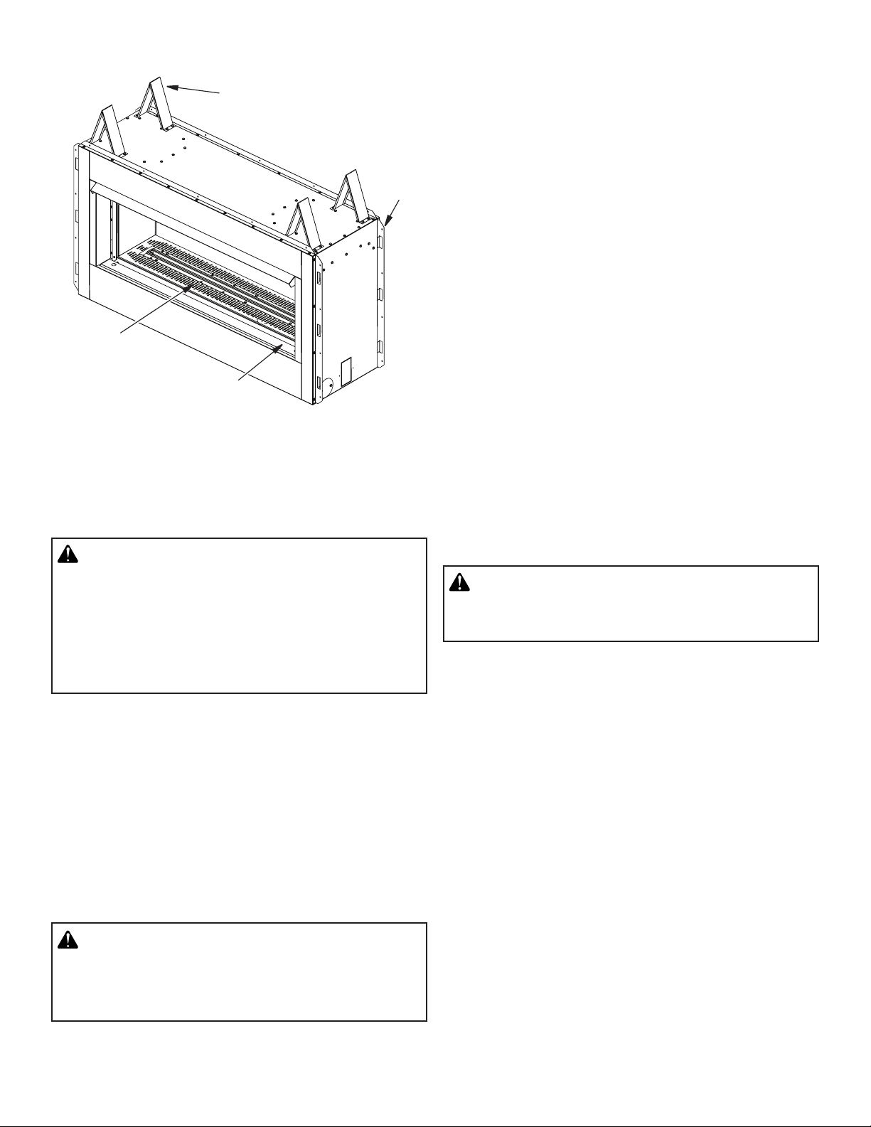
Pebble Pan
PRODUCT IDENTIFICATION
Top
Spacers
Access Door
Figure 1 - Outdoor Linear Fireplace
Nailing
Flange
PRODUCT FEATURES
OPERATION
This fireplace is clean burning. It requires no outside venting. There is
no heat loss out a vent or up a chimney. Heat is generated by realistic
flames. This fireplace is designed for outdoor use only. It has been
tested and approved to ANSI Z21.97 standard for outdoor decorative
gas appliance and CAN 1-2.21-M85 standard for gas-fired appliance
for outdoor installation.
INSTALLATION
CAUTION: This fireplace creates warm air currents. These currents move heat to wall surfaces next
to fireplace. Installing fireplace next to vinyl or cloth
wall coverings or operating fireplace where impurities
(such as, but not limited to, tobacco smoke, aromatic
candles, cleaning fluids, oil or kerosene lamps, etc.)
in the air exist, may discolor walls or cause odors.
Note: Standoff spacers are attached to the sides and top of your
fireplace, these spacers can be placed directly against wall or framing materials.
IMPORTANT: Make sure fireplace is level. If fireplace is not level, burner
will not work properly.
Use dimensions shown for rough openings to create the easiest
installation (see Figures 2 thru 5, page 5).
CHECK GAS TYPE
Use the correct gas type (natural or propane/LP) for your fireplace.
If your gas supply is not correct, do not install fireplace. Call dealer
where you bought fireplace for proper type gas.
WARNING: This appliance is equipped for either
natural gas or propane/LP gas but not both. Gas type
is indicated on the rating plate. Field conversion is
not permitted.
INSTALLATION CLEARANCES
WARNING: Maintain the minimum clearances. If you
can, provide greater clearances from floor, ceiling and
adjoining wall.
Carefully follow the instructions below. This will ensure safe installation.
CLEARANCES
Minimum clearances to combustibles for the fireplace are as follows:
*Back and sides 1"
Perpendicular walls 8"
Floor (From bottom of Fireplace) 0"
Ceiling (From top of opening) 42"
Top of Standoffs 0"
* For back and sides of fireplace, do not pack with insulation or other
materials.
OUTDOOR ENCLOSURE REQUIREMENTS
Must conform to one of the following conditions:
•Withwallsonallsides,butwithnooverheadcover;
•Withinapartialenclosurewhichincludesanoverheadcoverand
no more than two side walls. These side walls may be parallel,
asinbreezewayoratrightanglestoeachside;or
•Withina partial enclosure which includes an overhead cover
and three sidewalls, as long as 30% or more of the horizontal
periphery of the enclosure is permanently open.
SuperiorFireplaces.US.com 127035-01C4
Page 5
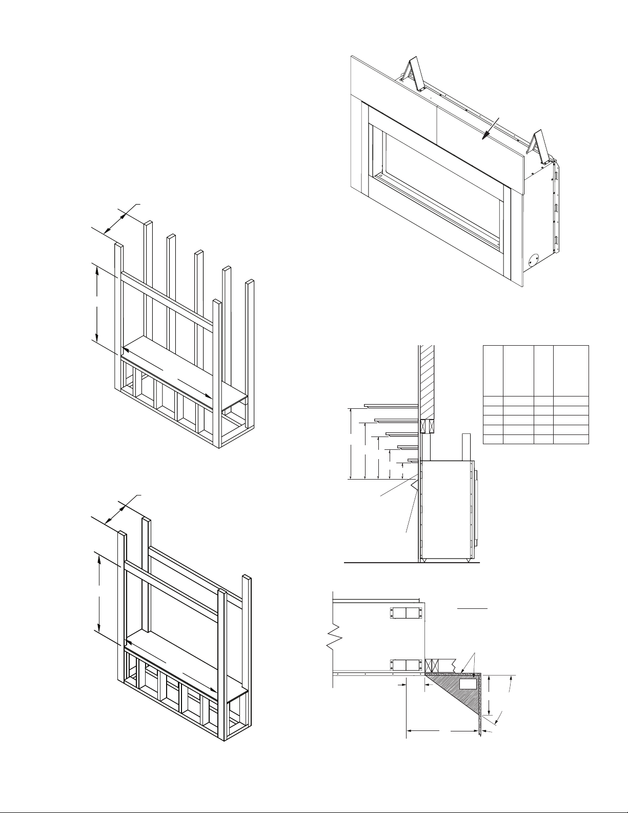
INSTALLATION Continued
15.25"
17.50"
53.25"
38"
15.25"
FRAMING AND FINISHING
Figure 2 shows typical framing of this fireplace. Figure 3 shows
framing for see-thru installation. All minimum clearances must be
met. Steel framing may be necessary or wood studs may be notched.
Concrete board is provided for facing around the fireplace as shown
in Figure 4.
If you are using a separate combustible mantel piece, refer to Figure 5
for proper installation height. You can install noncombustible mantels
at any height above the fireplace.
Note: Noncombustible mantels may discolor!
Concrete
Board
38"
53.25"
Figure 2 - Framing Clearances for One Sided Application
38"
Figure 4 - Installing Concrete Board
Note: All vertical
measurements are
from top of fireplace
hood opening to
bottom of mantel
shelf.
A
B
C
D
Noncombustible
material may project
off this surface above
the firebox hood
Supplied firebox
hood must be
used at all times.
Mantel
from
Mantel
Ref.
Depth Ref.
1
2
Wall
3
4
5
E
TOP VIEW
1 12" A 24"
2 9" B 21"
3 6" C 18"
4 4" D 16"
5 2" E 14"
Top of
Opening
53.25"
Figure 3 - Framing Clearances for See-Thru Application
SuperiorFireplaces.US.com127035-01C 5
Combustible
Material May
Be Used
4" to Face Opening
SAFE
ZONE
5"
33°
8"
Perpendicular
Wall
Figure 5 - Clearances for Combustible Mantels
Page 6
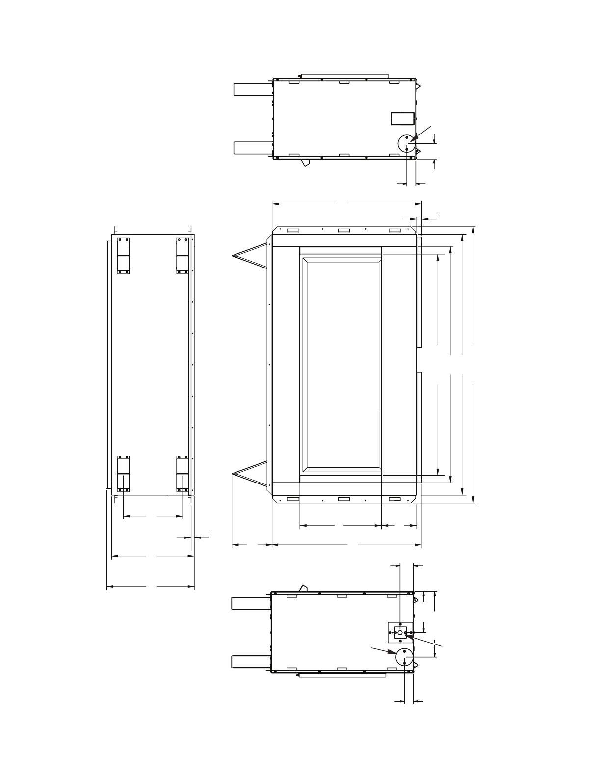
INSTALLATION Continued
1.816
Gas Line
Access
3.208
29 13/16"
1"
47"
44 1/16"
52"
55 1/16"
11 13/16"
16 1/2"
17 1/2"
5/8"
8 1/4"
16 9/32"
29 25/32"
Figure 6 - VRE4543E Series Dimensions
SuperiorFireplaces.US.com 127035-01C6
Gas Line
Access
7 1/32"
2.716
1.816
8.255
13.217
Electrical
Outlet
Page 7
INSTALLATION Continued
Mantel Clearances for Built-In Installation
If placing mantel above built-in fireplace, you must meet minimum
clearance between mantel shelf and top of fireplace opening.
NOTICE: If your installation does not meet the minimum
clearances shown, you must do one of the following:
•raisethemanteltoanacceptableheight
•removethemantel
CHECK GAS TYPE
Use proper gas type for the fireplace unit you are installing. If you
have conflicting gas types, do not install fireplace. See retailer where
you purchased the fireplace for proper fireplace according to your
gas type.
INSTALLING GAS PIPING TO FIREPLACE LOCATION
WARNING: A qualified service person must connect
fireplace to gas supply. Follow all local codes.
NOTICE: Surface temperatures of adjacent walls and
mantels become hot during operation. Walls and
mantels above the firebox may become hot to the
touch. If installed properly, these temperatures meet
the requirement of the national product standard. Follow all minimum clearances shown in this manual.
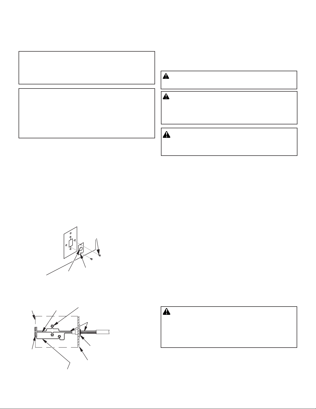
ELECTRICAL WIRING INSTRUCTIONS
1. Remove electrical cover plate with bushing from left side of fireplace front by removing 2 sheet metal screws as shown in Figure
7.
2. Slide power source wiring through electrical bushing opening and
electrical cover plate and make all necessary connections.
3. Slide all wiring connections in electrical housing as shown in
Figure 7.
4. Secure electrical cover plate with screws previously removed.
Note: Electrical housing and cover plate have sharp edges. Wear
protective gloves.
Sheet
Metal
Screws
Electrical
Cover
Plate
Wire Nut (3x)
(Not Supplied)
Power Source Wiring
(Not Supplied)
To Power
Source (120V)
Electrical Cover
Plate and
Electrical Bushing
Outer Wrapper
of Fireplace
Electrical
Housing
Receptacle
(Supplied)
Ground
(16GA Green)
Electrical
Bushing
14GA
Black &
White
Figure 7 - Connecting Electricity
CAUTION: Never connect propane/LP fireplace directly to the propane/LP supply. This fireplace requires
an external regulator (not supplied). Install the external
regulator between the fireplace and propane/LP supply.
WARNING: Never connect natural gas fireplace
to private (non-utility) gas wells. This gas is commonly known as wellhead gas.
Installation Items Needed
Before installing fireplace, make sure you have the items listed below.
• externalregulatorforpropane/LPunitonly(suppliedbyinstaller)
• piping(checklocalcodes)
• sealant(resistanttopropane/LPgas)
• equipmentshutoffvalve*
• testgaugeconnection*
• sedimenttrap(optional)
• teejoint
• pipewrench
• approvedexible gas linewithgasconnector (if allowedbylocal
codes) (not provided)
* An equipment shutoff valve with 1/8" NPT tap is an acceptable alternative to test gauge connection. Purchase the optional equipment
shutoff valve from your dealer.
For propane/LP units, the installer must supply an external regulator.
The external regulator will reduce incoming gas pressure. You must
reduce incoming gas pressure to between 11" and 14" of water. If
you do not reduce incoming gas pressure, fireplace regulator damage
could occur. Install external regulator with the vent pointing down as
shown in Figure 8, page 8. Pointing the vent down protects it from
freezing rain or sleet.
CAUTION: Use only new, black iron or steel pipe.
Internally-tinned copper tubing may be used in certain
areas. Check your local codes. Use pipe of 1/2" diameter or greater to allow proper gas volume to fireplace.
If pipe is too small, undue loss of volume will occur.
Installation must include an equipment shutoff valve, union and
plugged 1/8" NPT tap. Locate NPT tap within reach for test gauge hook
up. NPT tap must be upstream from fireplace (see Figure 8, page 8).
IMPORTANT: Install equipment shutoff valve in an accessible location. The equipment shutoff valve is for turning on or shutting off
the gas to the appliance.
SuperiorFireplaces.US.com127035-01C 7
Page 8
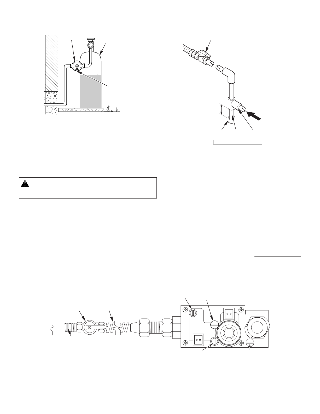
INSTALLATION Continued
External
Regulator
Figure 8 - External Regulator on Propane/LP Supply Tank with
Vent Pointing Down
Check your building codes for any special requirements for locating
equipment shutoff valve to fireplaces.
Apply pipe joint sealant lightly to male NPT threads. This will prevent
excess sealant from going into pipe. Excess sealant in pipe could
result in clogged fireplace valves. Never use sealant on flare threads.
Propane/LP
Supply Tank
Vent
Pointing
Down
Equipment Shutoff
Valve With 1/8" NPT
Tap*
Natural Gas
From Gas Meter
(5" W.C.** to
10.5" W.C.
Pressure)
Propane/LP
From External
Regulator
(11" W.C.**
to 14" W.C.
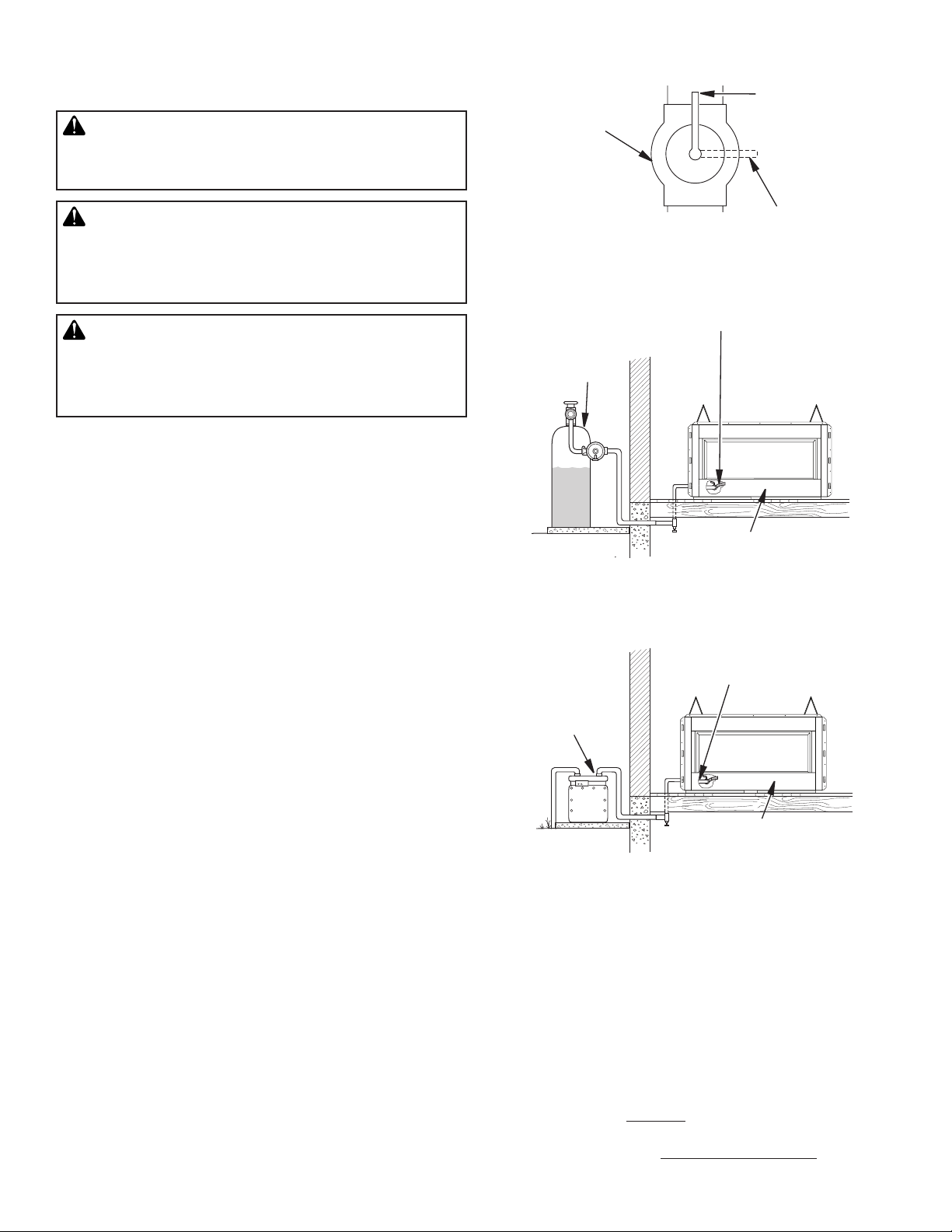
3" Minimum
Pressure)
Cap Pipe Tee
Nipple Joint
Sediment Trap
* Purchase the optional equipment shutoff valve from your dealer.
** Minimum inlet pressure for purpose of input adjustment.
Figure 9 - Gas Connection
WARNING: Use pipe joint sealant that is resistant
to liquid petroleum (LP) gas.
We recommend that you install a sediment trap in supply line as
shown in Figure 9. Locate sediment trap where it is within reach for
cleaning. Install in piping system between fuel supply and fireplace.
Locate sediment trap where trapped matter is not likely to freeze. A
sediment trap traps moisture and contaminants. This keeps them from
going into fireplace gas controls. If sediment trap is not installed or
is installed wrong, fireplace may not run properly.
Inlet Pressure Tap
Gas Shutoff
Valve
1/2" NPT Incoming
Gas Line
Note:
1) Wire connections not shown for clarity
2) * 1/8" NPT Plugged Tapping
Flexible Gas Line
Do NOT Kink
CONNECTING FIREPLACE TO GAS SUPPLY
Installation Items Needed
• 5/16"hexsocketwrenchornut-driver
• sealant(resistanttopropane/LPgas,notprovided)
1. Route flexible gas line (provided by installer) from equipment
shutoff valve to fireplace. Route flexible gas supply line through
one of the access holes on side of fireplace.
2. Attach flexible gas line from gas supply to control valve (see Figure
10).
3. Check all gas connections for leaks. See Checking Gas Connections, page 9.
Pilot Adjustment
IN
PILOTADJ
MAIN
PILOT
OUT
Outlet Pressure Tap
Set Screw
Figure 10 - Connecting Incoming Gas Line to Flex Gas Line
SuperiorFireplaces.US.com 127035-01C8
Page 9
INSTALLATION Continued
CHECKING GAS CONNECTIONS
WARNING: Test all gas piping and connections,
internal and external to unit, for leaks after installing
or servicing. Correct all leaks at once.
WARNING: Never use an open flame to check for
a leak. Apply a noncorrosive leak detection fluid to
all joints. Bubbles forming show a leak. Correct all
leaks at once.
CAUTION: Make sure external regulator has been
installed between propane/LP supply and fireplace.
See guidelines under Connecting Fireplace to Gas
Supply.
PRESSURE TESTING GAS SUPPLY PIPING SYSTEM
Test Pressures In Excess Of 1/2 PSIG (3.5 kPa)
1. Disconnect fireplace with its appliance main gas valve (control
valve) and equipment shutoff valve from gas supply piping system.
Pressures in excess of 1/2 psig will damage fireplace regulator.
2. Cap off open end of gas pipe where equipment shutoff valve was
connected.
3. Pressurize supply piping system by either opening propane/LP
supply tank valve for propane/LP gas or opening main gas valve
located on or near gas meter for natural gas or using compressed
air.
4. Check all joints of gas supply piping system. Apply noncorrosive
leak detection fluid to all joints. Bubbles forming show a leak.
5. Correct all leaks at once.
6. Reconnect fireplace and equipment shutoff valve to gas supply.
Check reconnected fittings for leaks.
Test Pressures Equal To or Less Than 1/2 PSIG (3.5 kPa)
1. Close equipment shutoff valve (see Figure 11).
2. Pressurize supply piping system by either opening propane/LP
supply tank valve for propane/LP gas or opening main gas valve
located on or near gas meter for natural gas or using compressed
air.
3. Check all joints from gas meter to equipment shutoff valve for natural
gas or propane/LP supply to equipment shutoff valve for propane/
LP (see Figures 12 or 13). Apply noncorrosive leak detection fluid
to all joints. Bubbles forming show a leak.
4. Correct all leaks at once.
Equipment
Shutoff
Valve
Figure 11 - Equipment Shutoff Valve
Equipment
Shutoff Valve
Propane/LP
Supply Tank
Gas Valve
Figure 12 - Checking Gas Joints for Propane/LP Gas Fireplace
Equipment
Shutoff Valve
Gas Meter
Figure 13 - Checking Gas Joints for Natural Gas Fireplace
PRESSURE TESTING FIREPLACE GAS CONNECTIONS
1. Open equipment shutoff valve (see Figure 11).
2. Open main gas valve located on or near gas meter for natural gas
or open propane/LP supply tank valve.
3. Make sure control knob of fireplace is in the OFF position.
4. Check all joints from equipment shutoff valve to gas control valve
(see Figures 12 or 13). Apply noncorrosive leak detection fluid to
all joints. Bubbles forming show a leak.
5. Correct all leaks at once.
6. Light fireplace (see Operation, page 14). Check all other internal
joints for leaks.
7. Turn off fireplace (see To Turn Off Gas to Appliance, page 14).
Open
Closed
Gas Valve
SuperiorFireplaces.US.com127035-01C 9
Page 10

FINISHING FIREPLACE FOR INSTALLATION
INSTALLATION Continued
UPGRADING VRE4543 TO SEE-THRU APPLICATION
The VRE4543 series fireplace come with the rear panel semi-installed.
If you will be using the fireplace for a one sided regular application,
you will need to finish the installation of the rear panel. If you will be
upgrading the fireplace to a see-thru, the rear panel will need to be
removed (See Upgrading VRE4543 Series to See-Thru Application).
1. Using self-tapping screws provided and holes on rear panel as
a guide, screw the rear panel to the fireplace as shown in Figure
14.
INSTALLING HOOD
1. Loosen screws at top of face opening and slide hood through
screws as shown in Figure 15.
2. Tighten screws securing hood to fireplace.
Removing Rear Panel
1. In the rear of the fireplace, locate screws at top of rear panel and
remove as shown in Figure 16. Discard screws and rear panel.
2. Unscrew mount bracket from top face as shown in Figure 17.
Discard mounting bracket and replace screws.
Figure 14 - Installing Rear Panel for Regular Applications
Figure 16 - Removing Rear Panel for See-Thru Applications
Figure 17 - Removing for See-Thru Applications
Figure 15 - Installing Hood
SuperiorFireplaces.US.com 127035-01C10
Page 11

INSTALLATION Continued
Removing False Door
1. In the rear of the fireplace, Unlock 3 door latches on top of
firebox using your fingers or the latch opener provided.
2. Hook opener over latch as shown in Figure 18. Swing the bottom of the opener down toward the door. You will not need to
pull down.
3. Tilt open false door 45° from the top of firebox and lift up to release
door from retaining channel.
Figure 18 - Latch Opener
Installing Access Door Retaining Brackets
1. Screw access door retaining brackets into the inner side face using
2 screws on both the left and right side as shown in Figure 20.
Installing Side Face Filler
1. Screw side face filler into firebox side baffle using 2 screws on
both the left and right side as shown in Figure 21.
Removing Rear Interior Wall
1. Through firebox opening in the front of the fireplace, unscrew 4
corner brackets from the firebox top (See Figure 19).
2. Remove 2 side walls and then the rear wall. Discard rear wall.
3. Replace 2 side walls and reinstall the corner brackets.
Rear
Panel
Bracket
Retaining
Bracket
Figure 20 - Installing Access Door Retaining Brackets for See-
Thru Applications
Side
Panel
Figure 19 - Removing Rear Interior Wall for See-Thru
Applications
SuperiorFireplaces.US.com127035-01C 11
Figure 21 - Installing Side Face Filler for See-Thru Applications
Page 12

INSTALLATION Continued
Installing Access Door
1. Place access door into rectangular opening in front of the glass
door with the slanted side facing forward. The slanted surface will
slide underneath the flange of the bottom face Insert tabs on side
of access door into slots on retaining brackets (See Figure 22).
5. Light switch is located on the right hand side as shown in Figure
24.
6. ON/OFF switch is located on the left hand side as shown in Figure
24.
Side
Filler
Access
Door
Flange on
Face Bottom
Figure 22 - Access Door for See-Thru Applications
Installing Hood
1. Install hood as shown in Figure 15 page 10.
Locating Control Module
1. Remove Access Plate (See Figure 22).
2. Remove 2 screws on top of the electronic access cover (See Figure
23).
3. Remove electronic access cover by gently pulling up and out of
the fireplace. There are two switches connected to cover.
4. The control module is located on the left as shown in Figure 24.
ON/OFF
Switch
Gas
Module
Figure 24 - Control Module (Face Bottom not shown for Clarity)
GLASS PEBBLE INSTALLATION
Remote
Receiver
Backup
Battery
Light
Switch
WARNING: Do not change or substitute glass
pebbles provided with this fireplace. If replacing, use
only replacement glass pebbles. See Replacement
Parts page 23.
Green glass pebbles are included with your fireplace.
1. Place glass pebbles in a single layer evenly on the pebble pan.
Make sure not to place any on the burner in the center of the
pebble pan.
Electronic
Access Cover
Figure 23 - Removing Control Access Cover (Face Bottom not
Remove
Screws
shown for Clarity)
SuperiorFireplaces.US.com 127035-01C12
GLASS PANEL INSTALLATION
WARNING: Do not slam or strike glass panel.
Damage can result in a hazardous condition.
Discontinue use of the appliance immediately if glass panel is
damaged and contact a qualified installer for repair. Only glass
panel certified with the appliance shall be used.
Page 13

INSTALLATION Continued
The glass panel assembly should be installed after the fireplace is
completely framed and finished. The brackets are attached to the
front side face of the fireplace using two screws as shown in Figure
25. Position the glass panel in the bracket so that it is securely in
place. The glass panel can be placed in two different height locations.
• Pushing and holding the LEARN button for 6 seconds will result
in clearing the transmitter security code from the module's
memory. The module will make three long beeps in succession
when it has been cleared.
Remote/Off Switch
ADJ.
Bracket
Screws
Glass
Panel
Figure 25 - Installing Glass Panel
GAS CONTROL MODULE SYSTEM
REMOTE CONTROL FEATURE
The module has a built in remote control receiver that allows the
user to program the remote transmitter at any time during or after
the installation of the burner.
1. There is a switch located on the right side of the module that
reads REMOTE/OFF (Figure 26).
2. When the remote/off switch is in the OFF position, the burner
will operate from the rocker switch or wall switch connected to
the two BROWN wires on the module.
3. When the remote/off is in the REMOTE position the burner will
operate from the Remote Control Transmitter.
NOTE: The module must be programmed to the Remote Control
Transmitter.
• To program the module (make sure the system has power),
locate the learn button (Figure 27) on the module. Locate the
metal shield that is covering the module and remove the screw
on top. Use a small thin object like a paper clip (not sharp points)
to press and release the learn button. There will be a beep sound
from the module. Then press any button on the remote transmitter. Once the module's internal receiver accepts the transmitter
code, there will be a series of confirming beeps.
• The remote system is ready for use.
“S” Pilot Connection
“I” Pilot Connection
Figure 26 - Gas Module Right Side
Learn Button
AUX Connection
Figure 27 - Gas Module Left Side
IGNITOR ASSEMBLY
The ignitor assembly is factory preset for proper ignition of the burner.
Alterations may have occurred during shipping and handling. Call a
qualified service person to readjust the ignitor assembly if necessary.
The ignitor should be positioned as shown in Figure 28.
Note: Figure 28, shows the correct positioning of the ignitor and
sensing rod.
If your ignitor assembly does not meet these requirements:
• turnapplianceoff(seeTo Turn Off Gas to Appliance, page 14).
• seeTroubleshooting, page 17.
Note: Reference only, not to scale
Ignitor
Ground
Electrode
Sensing
Rod
Spark
Gap
0.120
0.8000
Figure 28 - Ignitor
SuperiorFireplaces.US.com127035-01C 13
Page 14

OPERATION
FOR YOUR SAFETY
READ BEFORE LIGHTING
WARNING: If you do not follow these instructions
exactly, a fire or explosion may result causing property
damage, personal injury or loss of life.
A. This appliance does not have a pilot, it is equipped with an
ignition device which automatically lights the pilot. Do not light
pilot by hand.
B. BEFORE LIGHTING smell all around the appliance area for gas.
Be sure to smell next to the floor because some gas is heavier
than air and will settle on the floor.
WHAT TO DO IF YOU SMELL GAS
•Donottrytolightanyappliance.
•Donottouchanyelectricswitch;donotuseanyphoneinyour
building.
•Immediatelycallyourgassupplierfromaneighbor’sphone.
Follow the gas supplier’s instructions.
•Ifyoucannotreachyourgassupplier,calltheredepartment.
C.
Do not use this appliance if any part has been under water. Immediately call a qualified service technician to inspect the appliance
and to replace any part of the control system and any gas control
which has been under water.
LIGHTING
INSTRUCTIONS
This appliance requires 120V electricity for normal operation. Control
module should be plugged into electrical outlet located underneath
firebox bottom. Back up battery supply is available for power outages.
1. STOP! Read the safety information, column 1.
2. Make sure equipment shutoff valve is fully open.
3. Turn safety shutoff switch to the OFF position.
4. Remove access cover.
5. Turn equipment shutoff valve clockwise to the OFF position
(see Figure 29). Do not force.
6. Wait five (5) minutes to clear out any gas. Then smell for gas,
including near the floor. If you smell gas, STOP! Follow “B” in the
safety information. If you don't smell gas, go to the next step.
7. Turn equipment shutoff valve counterclockwise to the ON
position. Do not force.
8. Replace access cover.
9. Turn on all electric power to appliance.
10. Turn safety shutoff switch to the ON position.
11. Visually locate ignitor. Ignitor should begin to spark and main
burner should ignite once flame appears at pilot.
•Iflightingapplianceforthersttimeeachseason,itmaytake
several attempts before supply gas can reach pilot and main
burners.
•Ifappliancewillnotstaylitafterseveralattempts,followinstruc-
tions under To Turn Off Gas To Appliance and call your service
technician or gas supplier.
Incoming
Gas Line
Equipment
Shutoff Valve
CAUTION: Do not try to adjust heating levels by
using the equipment shutoff valve.
TO TURN OFF GAS
TO APPLIANCE
1. Push remote control to “OFF” position.
2. Turn off all electric power to appliance if service is to be performed.
3. Turn equipment shutoff valve clockwise to OFF. Do not force.
4. Replace access cover.
IN
PILOTADJ
MAIN
PILOT
OUT
Figure 29 - Turning Equipment Shutoff Valve to the OFF Position
SuperiorFireplaces.US.com 127035-01C14
Page 15

CLEANING AND MAINTENANCE INSPECTING BURNERS
WARNING: Turn off fireplace and let cool before
cleaning.
CAUTION: You must keep control areas, burner
and circulating air passageways of fireplace clean.
Inspect these areas of fireplace before each use. Have
fireplace inspected yearly by a qualified service person.
WARNING: Failure to keep the primary air
opening(s) of the burner(s) clean may result in sooting
and property damage.
BURNER INJECTOR HOLDER AND PILOT AIR INLET HOLE
BURNER PRIMARY AIR HOLES
Air is drawn into the burner through the holes in the fitting at the
burner entrance. These holes may become blocked with dust or lint.
Periodically inspect these holes for any blockage and clean if needed.
Blocked air holes will create soot.
MAIN BURNER
Periodically inspect all burner flame holes with the fireplace running.
Some burner flame holes may become blocked by debris or rust, with
no flame present. If so, turn off fireplace and let cool. Remove blockage.
Blocked burner flame holes will create soot.
BURNER FLAME PATTERN
WARNING: If yellow tipping occurs, your fireplace
could produce increased levels of carbon monoxide.
The primary air inlet holes allow the proper amount of air to mix with
the gas. This provides a clean burning flame. Keep these holes clear
of dust, dirt, lint and pet hair. Clean these air inlet holes prior to each
heating season. Blocked air holes will create soot. We recommend
that you clean the unit every three months during operation and have
fireplace inspected yearly by a qualified service person.
We also recommend that you keep the burner tube and pilot assembly
clean and free of dust and dirt. To clean these parts we recommend
using compressed air no greater than 30 PSI. Your local computer
store, hardware store or home center may carry compressed air in
a can. If using compressed air in a can, please follow the directions
onthecan.Ifyoudon’tfollowdirectionsonthecan,youcoulddamage the ignitor.
1. Shut off the unit. Allow the unit to cool for at least thirty minutes.
2. Inspect burner, air shutter and orifice for dust and dirt (see Figure
30).
3. Blow air through the ports/slots and holes in the burner.
4. Check the orifice located at the end of the burner tube again. Remove
any large particles of dust, dirt, lint or pet hair with a soft cloth or
vacuum cleaner nozzle.
5. Blow air into the primary air holes on the injector holder.
6. In case any large clumps of dust have now been pushed into the
burner repeat steps 3 and 4 above.
Burner
Ports/Slots
NOTICE: Do not mistake orange flames with yellow
tipping. Dirt or other fine particles enter the fireplace
and burn causing brief patches of orange flame.
Burner flames will be steady, not lifting or floating. Flame patterns will
be different from unit to unit and will vary depending on installation
type and weather conditions. This can be dangerous. Inspect flames
after installation to ensure proper installation and performance.
If burner flame pattern differs from that described:
• turnreplaceoff(seeTo Turn Off Gas to Appliance, page 14)
• seeTroubleshooting, page 17
REPLACING LIGHT BULB
Light assembly is located underneath the burner assembly (see page
24 for reference).
1. Unplug power supply.
2. Remove access door (Figure 22, page 12).
3. Remove glass panel if installed (Figure 25, page 13).
4. Remove rear interior panels (Figure 19, page 11).
5. Remove glass Pebbles.
6. Remove six screws holding the pebble pan (see item #17 on
page 22 for reference).
7. Using a small slotted screw driver, carefully slide it under the
edge of light bulb cover and pry it open. Pull burned out bulb
and replace.
8. Replace all in reverse order.
Venturi
Air Shutter
Figure 30 - Injector Holder On Outlet Burner Tube
SuperiorFireplaces.US.com127035-01C 15
Page 16

Orange
Orange
Orange
Red
Brown
Black
Solenoid
White
Brown
Brown
Green
Ignitor
Pilot
I
S
AUX
AF-5000MOD
AF-4000
AF-4000B/P
Control Module
Black
Black
SWI
SWI
(GND)
Red
HI/LO
Main
Black
BATTERY PACK
Black
Red
Black
Red
SIZE
"AA"
SIZE
"AA"
SIZE
"AA"
SIZE
"AA"
AC
Power
Adapter
110V
MAX. 15 AMPS
WIRING DIAGRAM
SuperiorFireplaces.US.com 127035-01C16
Page 17

TROUBLESHOOTING
WARNING: Turn off appliance and let cool before servicing. Only a qualified service person should service
and repair appliance.
Note: All troubleshooting items are listed in order of operation.
Remote /Ignitor has a special feature. It will allow heat from the burner to dry the probe and burner assembly due to excess moisture, caused
by rain, humidity or condensation. To activate:
• Press and hold the HI and LO buttons on the transmitter for 30-45 seconds. This allows the sparking to start and the burner to ignite.
• Release the HI and LO buttons, after the allotted time, sparking will stop and the burner will go out.
• Press and hold the ON button and sparking will start again and burner should ignite.
• Release the ON button. The sparking will stop, and the burner should stay ON.
• Repeat if necessary.
OBSERVED PROBLEM
When ''ON'' button on remote control is
pressed, there is no spark at ignitor assembly
When ''ON'' button on remote control is
pressed, there is spark at ignitor but no
ignition
POSSIBLE CAUSE
1. Ignitor electrode not connected to ignitor
cable
2. Ignitor cable pinched or wet
3. Broken ignitor cable
4. Bad ignitor
5. Ignitor electrode positioned wrong
6. Ignitor electrode broken
7. Battery not installed, battery power low or
battery not installed correctly (electronic
ignition models only)
1. Gas supply turned off or equipment shutoff
valve closed
2.
Air in gas lines when installed
3. Depleted gas supply (propane/LP only)
4. Control module not in REMOTE position
5. Gas control valve pressure setting is not
correct
6. Inlet gas pressure is too low
7. Burner orifice(s) clogged
8. Wire disconnected from gas control
9. Ground wire issue
REMEDY
1. Reconnect ignitor cable
2. Free ignitor cable if pinched by any metal
or tubing. Keep ignitor cable dry
3. Replace ignitor
4. Replace ignitor
5. Adjust ignitor wires as shown in Figure
28 on page 13. Replace ignitor assembly
if repositioning does not correct the
problem
6. Replace ignitor
7. Install new alkaline battery in remote
control and battery pack. Verify batteries
are installed correctly. (5.4 volts batteries required to operate valve system)
1. Turn on gas supply or open equipment
shutoff valve
2. Repeat igniting operation until air is
removed
3. Contact local propane/LP gas company
4. Set control module to REMOTE position
5. Contact qualified service person to check
pressure
6. Contact local natural or propane/LP gas
company
7. Clean burner (see Cleaning and Maintenance, page 15) or replace burner
orifice(s)
8.
See Wiring Diagram, page 16
9.
Verify black ground wire from module is
secured under screw adjacent to ignitor
SuperiorFireplaces.US.com127035-01C 17
Page 18

OBSERVED PROBLEM
Delayed ignition of burner
TROUBLESHOOTING Continued
POSSIBLE CAUSE
1. Manifold pressure is too low
2. Burner orifice clogged
REMEDY
1. Contact local natural or propane/LP gas
company
2. Clean burner (see Cleaning and Maintenance, page 18) or replace burner
orifice(s)
Burner backfiring during combustion
Slight smoke or odor during initial operation
Appliance produces a whistling noise when
burners are lit
White powder residue forming within burner
box or on adjacent walls or furniture
Remote does not function
Appliance produces a clicking/ticking noise
just after burners are lit or shut off
1. Burner orifice is clogged or damaged
2. Damaged burner
1. Residues from manufacturing processes
1. Air in gas line
2. Air passageways on appliance blocked
3. Dirty or partially clogged burner orifice.
1. When heated, vapors from furniture polish, wax, carpet cleaners, etc. may turn
into white powder residue
1. Battery is not installed. Battery power is
low
1. Metal expanding while heating or contracting while cooling
2. Ignitor Assembly is out of position
3. Wind is disturbing the burner flame and
the ignitor assembly is relighting the
burner
4. Wire connection loose or wire broken
1. Clean burner (see Cleaning and Maintenance, page 18) or replace burner orifice
2. Replace damaged burner
1. Problem will stop after a few hours of
operation
1. Operate burners until air is removed
from line. Have gas line checked by local
natural or propane/LP gas company
2. Observe minimum installation clearances
(see pages 5 through 8)
3. Clean burner (see Cleaning and Maintenance, page 18) or replace burner
orifice(s)
1. Turn appliance off when using furniture
polish, wax, carpet cleaners or similar
products
1. Replace batteries in battery pack and in
hand-held remote
1. This is normal with most appliances. If
noise is excessive, contact qualified service
person
2. Check ignitor position and adjust if
needed. See Figure 28 page 16.
3. Should wind disturb the burner flame, the
ignitor will automatically spark to relight
the burner. This is normal when the appliance is installed outdoors in windy
conditions.
4. Check wiring connections (see wiring
diagram, page 20). Replace wire harness
if necessary.
SuperiorFireplaces.US.com 127035-01C18
Page 19

TROUBLESHOOTING Continued
WARNING: If you smell gas
•Shutoffgassupply.
•Donottrytolightanyappliance.
•Donottouchanyelectricalswitch;donotuseanyphoneinyourbuilding.
•Immediatelycallyourgassupplierfromaneighbor’sphone.Followthegassupplier’sinstructions.
•Ifyoucannotreachyourgassupplier,calltheredepartment.
IMPORTANT: Operating fireplace where impurities in air exist may create odors. Cleaning supplies, paint, paint remover, cigarette smoke,
cements and glues, new carpet or textiles, etc., create fumes. These fumes may mix with combustion air and create odors. These odors
will disappear over time.
OBSERVED PROBLEM
Appliance produces unwanted odors
Appliance shuts off in use
Gas odor even when control knob is in OFF
position
Module makes one beep every one second
Gas odor during combustion
POSSIBLE CAUSE
1. Appliance burning vapors from paint, hair
spray, glues, cleaners, chemicals, new carpet,
etc. (See IMPORTANT statement above)
2. Low fuel supply (propane/LP only)
3. Gas leak. See Warning statement at top
of page
1. Low line pressure
1. Gas leak. See Warning statement at top
of page
2. Control valve or gas control defective
1. The burner did not successfully ignite
1. Gas leak. See Warning statement at top
of page
REMEDY
1. Stop using odor causing products while
appliance is running
2. Refill supply tank (propane/LP only)
3. Locate and correct all leaks (see Checking
Gas Connections, page 10)
1. Contact local natural or propane/LP gas
company
1. Locate and correct all leaks (see Checking
Gas Connections, page 10)
2. Replace control valve or gas control
1. Press OFF then ON buttons to re-attempt
ignition. Refer to '' When ''on'' button on
remote control is pressed, there is spark
at ignitor but no ignition'' on page 21
1. Locate and correct all leaks (see Checking
Gas Connections, page 10)
SuperiorFireplaces.US.com127035-01C 19
Page 20

MODELS VRE4543EN AND VRE4543EP
4
PARTS
3
4
4
5
6
4
2
18
17
16
12
1
7
11
8
9
10
13
12
14
15
19
4
22
20
21
SuperiorFireplaces.US.com 127035-01C20
Page 21

PARTS
This list contains replaceable parts used in your fireplace. When ordering parts, follow the instructions listed under Replacement Parts on
page 23 of this manual.
WARNING: Contact an IHP dealer to obtain any of these parts. Never use substitute materials not ap-
proved by IHP. Use of non-approved parts can result in poor performance and safety hazards.
KEY
NO. PART NO. DESCRIPTION
1 126396-01 Pilot Bracket • • 1
126396-02 Pilot Bracket Top • • 1
2 126398-01 Ignitor, Direct Spark • • 1
3 125752-02 Burner Assembly Stainless Steel • • 1
4 125961-02 Light Assembly w/ Wire Harness • • 1
126130-02 Light Bulb, G9 120V/20W • • 2
5 24874 Orifice, #32 • 1
23106 Orifice, #49 • 1
6 14296 Brass Elbow • • 1
7 114027-01 Grommet SC 1/2'' ID 1 1/16'' OD • • 1
8 116573-01 Flat Washer • • 7
9 11214 Bulkhead Fitting • • 1
10 14399 Brass Elbow • • 2
11 111817-01 Flextube, • • 1
12 125932-01 Burner Gasket • • 2
13 126050-02 Electronic Access Cover LVFO • • 1
14 126051-01 Insulation Heat Shield • • 1
15 125976-02 Bracket Valve Components • • 1
16 14607 Switch, Rocker ON/OFF Remote • • 1
17 11408 Bushing, Double Insulation • • 1
18 125643-01 Module, Control • • 1
19 125067-01 Module, Power • • 1
20 125068-01 Battery, Backup (W/Batteries) • • 1
21 125236-01 Valve NG. • 1
125236-02 Valve LP. • 1
22 14396 Connector, 3/8 Tube X 3/8 MPT • • 1
PARTS AVAILABLE NOT SHOWN
121129-10 Control Module Wire Harness • • 1
121129-11 Remote Receiver Wire Harness • • 1
125643-04 Remote Control • • 1
14253 30" Flex Line • • 1
125999-04 Green Pebbles (6 lbs) • • 1
125066-01 A/C Adapter • •
VRE4543EN
F0497
VRE4543EP
F0498 QTY.
SuperiorFireplaces.US.com127035-01C 21
Page 22

PARTS
MODELS VRE4543EN AND VRE4543EP
This list contains replaceable parts used in your fireplace. When ordering parts, follow the instructions listed under Replacement Parts on
page 23 of this manual.
WARNING: Contact an IHP dealer to obtain any of these parts. Never use substitute materials not ap-
proved by IHP. Use of non-approved parts can result in poor performance and safety hazards.
1
14
13
1
5
6
9
7
8
9
10
11
12
13
10
1
17
8
1
2
2
4
7
3
5
16
15
16
KEY NO. PART NO. DESCRIPTION
VRE4543EN
F0497
VRE4543EP
F0498
QTY.
1 125847-01 Top Spacer • • 4
2 125757-02 Top Nailing Flange • • 2
3 125805-01 Rear Panel • • 1
4 125741-02 False Door Assembly • • 1
5 125757-01 Side Nailing Flange • • 4
6 110037-01 Electric Duct Assembly • • 1
7 21171 Cover Gas Conduit • • 2
8 125767-02 Access Cover Retaining Bracket • • 2
9 125763-02 Corner Bracket Stainless • • 4
10 125766-02 Side Walls • • 2
11 125761-02 Rear Wall LVFO • • 1
12 125768-03 Access Door Stainless • • 1
13 125766-02 Side Face Filler Stainless • • 2
14 125975-02 Fireplace Hood Stainless • • 1
15 126399-01 Glass, tempered • • 1
16 126397-01 Bracket, Glass Retainer • • 2
17 125753-02 Pebble Pan LVFO • • 1
SuperiorFireplaces.US.com 127035-01C22
Page 23

SPECIFICATIONS
VRE4543EN
• Rating(Variable):25/39,000Btu/Hr
• GasType:NaturalGas
• Ignition:Electronic
• PressureManifoldSetting:3.5"W.C.
• InletGasPressure(in.ofwater):
Maximum - 10.5" W.C.,
Minimum* - 5.5" W.C.
* For purposes of input adjustment
VRE4543EP
• Rating(Variable):29/37,000Btu/Hr
• GasType:Propane/LPGas
• Ignition:Electronic
• PressureManifoldSetting:10.5"W.C.
• InletGasPressure(in.ofwater):
Maximum - 14" W.C.
Minimum* - 11" W.C.
* For purposes of input adjustment
SERVICE HINTS
When Gas Pressure Is Too Low
• pilotwillnotstaylit
• burnerwillhavedelayedignition
• replacewillnotproducespeciedheat
• forpropane/LPunit,propane/LPgassupplymaybelow
You may feel your gas pressure is too low. If so, contact your local
gas supplier.
ACCESSORIES
NOTICE: All accessories may not be available for all
fireplace models.
Purchase these accessories from your local dealer.
If they can not supply these accessories contact IHP at
Superiorfireplaces.US.com. for information.
SMOOTH GLASS PEBBLES (6 LBS)
F1101 - GP43SO - Speckled Orange
F1097 - GP43A - Amber
F1099 - GP43G - Green
F1098 - GP43B - Blue
OUTDOOR SEE-THRU DOOR KIT
F1029 - LVOST
TECHNICAL SERVICE
You may have further questions about installation, operation, or
troubleshooting. Please contact your IHP dealer for any questions
or concerns. When contacting your dealer please have your model
and serial numbers of your fireplace ready. You can also visit our web
site at Superiorfireplaces.US.com.
REPLACEMENT PARTS
See Pages 20 to 22 for a complete replacement parts list. Use only
parts supplied from the manufacturer.
Normally, all parts should be ordered through your IHP distributor
or dealer. Parts will be shipped at prevailing prices at time of order.
When ordering repair parts, always give the following information:
1. The model number of the fireplace.
2. The serial number of the fireplace.
3. The part number.
4. The description of the part.
5. The quantity required.
6. The installation date of the fireplace.
If you encounter any problems or have any questions concerning the
installation or application of this fireplace, please contact your dealer.
IHP
1508 Elm Hill Pike, Suite 108
Nashville, TN 37210
Visit us at Superiorfireplaces.US.com.
SuperiorFireplaces.US.com127035-01C 23
Page 24

NOTES
______________________________________________________
______________________________________________________
______________________________________________________
______________________________________________________
______________________________________________________
______________________________________________________
______________________________________________________
______________________________________________________
______________________________________________________
______________________________________________________
______________________________________________________
______________________________________________________
______________________________________________________
______________________________________________________
______________________________________________________
______________________________________________________
______________________________________________________
______________________________________________________
______________________________________________________
______________________________________________________
______________________________________________________
______________________________________________________
______________________________________________________
______________________________________________________
______________________________________________________
______________________________________________________
______________________________________________________
______________________________________________________
______________________________________________________
______________________________________________________
______________________________________________________
______________________________________________________
______________________________________________________
______________________________________________________
______________________________________________________
______________________________________________________
______________________________________________________
SuperiorFireplaces.US.com 127035-01C24
Page 25

NOTES
______________________________________________________
______________________________________________________
______________________________________________________
______________________________________________________
______________________________________________________
______________________________________________________
______________________________________________________
______________________________________________________
______________________________________________________
______________________________________________________
______________________________________________________
______________________________________________________
______________________________________________________
______________________________________________________
______________________________________________________
______________________________________________________
______________________________________________________
______________________________________________________
______________________________________________________
______________________________________________________
______________________________________________________
______________________________________________________
______________________________________________________
______________________________________________________
______________________________________________________
______________________________________________________
______________________________________________________
______________________________________________________
______________________________________________________
______________________________________________________
______________________________________________________
______________________________________________________
______________________________________________________
______________________________________________________
______________________________________________________
______________________________________________________
______________________________________________________
SuperiorFireplaces.US.com127035-01C 25
Page 26

NOTES
______________________________________________________
______________________________________________________
______________________________________________________
______________________________________________________
______________________________________________________
______________________________________________________
______________________________________________________
______________________________________________________
______________________________________________________
______________________________________________________
______________________________________________________
______________________________________________________
______________________________________________________
______________________________________________________
______________________________________________________
______________________________________________________
______________________________________________________
______________________________________________________
______________________________________________________
______________________________________________________
______________________________________________________
______________________________________________________
______________________________________________________
______________________________________________________
______________________________________________________
______________________________________________________
______________________________________________________
______________________________________________________
______________________________________________________
______________________________________________________
______________________________________________________
______________________________________________________
______________________________________________________
______________________________________________________
______________________________________________________
______________________________________________________
______________________________________________________
SuperiorFireplaces.US.com 127035-01C26
Page 27

Innovative Hearth Products
Superior™ Brand Gas Fireplaces, Stoves and Inserts
20 Year Limited Warranty
THE WARRANTY
Innovative Hearth Products ("IHP") 20 Year Limited Warranty warrants your Superior™ Brand gas fireplace, Stove or Insert ("Product") to be free from defects in materials
and workmanship at the time of manufacture. The Product body and firebox carry the 20 Year Limited Warranty. Ceramic glass carries the 20 Year Limited Warranty against
thermal breakage only. After installation, if covered components manufactured by IHP are found to be defective in materials or workmanship during the 20 Year Limited
Warranty period and while the Product remains at the site of the original installation, IHP will, at its option, repair or replace the covered components. If repair or replacement
is not commercially practical, IHP will, at its option, refund the purchase price or wholesale price of the IHP product, whichever is applicable. IHP will also pay IHP prevailing labor rates, as determined in its sole discretion, incurred in repairing or replacing such components for up to five years. THERE ARE EXCLUSIONS AND LIMITATIONS
to this 20 Year Limited Warranty as described herein.
COVERAGE COMMENCEMENT DATE
Warranty coverage begins on the date of installation. In the case of new home construction, warranty coverage begins on the date of first occupancy of the dwelling or six
months after the sale of the Product by an independent IHP dealer/distributor, whichever occurs earlier. The warranty shall commence no later than 24 months following
the date of product shipment from IHP, regardless of the installation or occupancy date.
EXCLUSIONS AND LIMITATIONS
This 20 Year Limited Warranty applies only if the Product is installed in the United States or Canada and only if operated and maintained in accordance with the printed
instructions accompanying the Product and in compliance with all applicable installation and building codes and good trade practices.
This warranty is non-transferable and extends to the original owner only. The Product must be purchased through a listed supplier of IHP and proof of purchase must be
provided. The Product body and firebox carry the 20 Year Limited Warranty from the date of installation. Vent components, trim components and paint are excluded from
this 20 Year Limited Warranty. The following do not carry the 20 Year Limited Warranty but are warranted as follows:
Burner – Repair or replacement for one year from the date of installation
Gas components – Repair or replacement for one year from the date of installation
Gaskets – Repair or replacement for one year from the date of installation
Logs – Replacement for one year from the date of installation against thermal breakage only
Optional blowers & remote controls – Repair or replacement for one year from the date of installation
Optional glass doors – Repair or replacement for 90 days from the date of installation
Tempered glass - Replacement for one year from the date of installation
Labor coverage – Prevailing IHP labor rates apply for the warranty period of the component
Parts not otherwise listed carry a 90 day warranty from the date of installation.
Whenever practicable, IHP will provide replacement parts, if available, for a period of 10 years from the last date of manufacture of the Product.
IHP will not be responsible for: (a) damages caused by normal wear and tear, accident, riot, fire, flood or acts of God; (b) damages caused by abuse, negligence, misuse, or
unauthorized alteration or repair of the Product affecting its stability or performance (The Product must be subjected to normal use. The Product is designed to burn either
natural or propane gas only. Burning conventional fuels such as wood, coal or any other solid fuel will cause damage to the Product, will produce excessive temperatures
and could result in a fire hazard.); (c) damages caused by failing to provide proper maintenance and service in accordance with the instructions provided with the Product;
(d) damages, repairs or inefficiency resulting from faulty installation or application of the Product.
IHP is not responsible for inadequate fireplace system draft caused by air conditioning and heating systems, mechanical ventilation systems, or general construction conditions which may generate negative pressure in the room in which the appliance is installed. Additionally IHP assumes no responsibility for drafting conditions caused by
venting configurations, adjoining trees or buildings, adverse wind conditions or unusual environmental factors and conditions that affect the operation of the unit.
This 20 Year Limited Warranty covers only parts and labor as provided herein. In no case shall IHP be responsible for materials, components or construction, which are not
manufactured or supplied by IHP or for the labor necessary to install, repair or remove such materials, components or construction. Additional utility bills incurred due to
any malfunction or defect in equipment are not covered by this warranty. All replacement or repair components will be shipped F.O.B. from the nearest stocking IHP factory.
LIMITATION ON LIABILITY
It is expressly agreed and understood that IHP’s sole obligation and the purchaser’s exclusive remedy under this warranty, under any other warranty, expressed or implied,
or in contract, tort or otherwise, shall be limited to replacement, repair, or refund, as specified herein.
In no event shall IHP be liable for any incidental or consequential damages caused by defects in the Product, whether such damage occurs or is discovered before or
after repair or replacement, and whether such damage is caused by IHP’s negligence. IHP has not made and does not make any representation or warranty of fitness for a
particular use or purpose, and there is no implied condition of fitness for a particular use or purpose.
IHP makes no expressed warranties except as stated in this 20 Year Limited Warranty. The duration of any implied warranty is limited to the duration of this expressed warranty.
No one is authorized to change this 20 Year Limited Warranty or to create for IHP any other obligation or liability in connection with the Product. Some states and provinces
do not allow the exclusion or limitation of incidental or consequential damages, so the above limitations or exclusions may not apply to you. The provisions of this 20 Year
Limited Warranty are in addition to and not a modification of or subtraction from any statutory warranties and other rights and remedies provided by law.
INVESTIGATION OF CLAIMS AGAINST WARRANTY
IHP reserves the right to investigate any and all claims against this 20 Year Limited Warranty and to decide, in its sole discretion, upon the method of settlement.
To receive the benefits and advantages described in this 20 Year Limited Warranty, the appliance must be installed and repaired by a licensed contractor approved by IHP.
Contact IHP at the address provided herein to obtain a listing of approved dealers/distributors. IHP shall in no event be responsible for any warranty work done by a
contractor that is not approved without first obtaining IHP's prior written consent.
HOW TO REGISTER A CLAIM AGAINST WARRANTY
In order for any claim under this warranty to be valid, you must contact the IHP dealer/distributor from which you purchased the product. If you cannot locate the dealer/
distributor, then you must notify IHP in writing. IHP must be notified of the claimed defect in writing within 90 days of the date of failure. Notices should be directed to the
IHP Warranty Department at 1508 Elm Hill Pike, Suite 108; Nashville, TN 37210 or visit our website at WWW.SUPERIORFIREPLACES.US.COM.
Printed in U.S.A. © 2013 Innovative Hearth Products LLC
P/N 900223-00, Rev. NC 12/2013
Innovative Hearth Products
SuperiorFireplaces.US.com127035-01C 27
1508 Elm Hill Pike, Suite 108 • Nashville, TN 37210
Page 28

WARRANTY
P127035-01
KEEP THIS WARRANTY
Model Number
Serial Number
Date Installed
Dealer's Name
Dealer's Phone Number
Keep receipt for warranty verification
Innovative Hearth Products reserves the right to make changes at any time, without notice, in
design, materials, specifications, prices and also to discontinue colors, styles and products. Consult
your local distributor for fireplace code information.
Printed in U.S.A. © 2014 IHP LLC
P/N 127035-01 Rev. C 04/2015.
1508ElmHillPike,Suite108•Nashville,TN37210
 Loading...