

Superior VRE3236ZENWS, VRE3236ZENWH, VRE3236ZEPWS, VRE3236ZEPWH, VRE3242ZENWH Installation And Operation Instructions Manual
...Page 1
P900990-00
PFS
USC
Installation and Operation Instructions
OUTDOOR DECORATIVE GAS FIREPLACE
P/N 900990-00 REV. C 06/2019
Ce manuel est disponible en francais,
simplement en faire la demande. Numéro
de la pièce 900990-03.
Report No. F14-020
INSTALLER: Leave this manual with the appliance.
CONSUMER: Retain this manual for future reference.
WHEN USED AS AN OUTDOOR APPLIANCE
CARBON MONOXIDE WARNING
DANGER
• This appliance can produce
carbon monoxide which has
no odor.
• Using it in an enclosed space
can kill you.
• Never use this appliance in
an enclosed space such as a
camper, tent, car or home.
Models
VRE3236ZENWS
®
VRE3236ZENWH
VRE3236ZEPWS
VRE3236ZEPWH
VRE3242ZENWS
VRE3242ZENWH
VRE3242ZEPWS
VRE3242ZEPWH
Installateur : Laissez cette notice avec l’appareil.
Consommateur : Conservez cette notice pour consultation ultérieure.
WARNING: For Outdoor Use Only.
DANGER
IF YOU SMELL GAS:
1. Shut off gas to appliance.
2. Extinguish any open flame.
3. If odor continues, keep away from the appliance and
immediately call your gas supplier or fire department.
WARNING: Do not store gasoline or other flammable vapors and liquids in the vicinity of this or any other appli-
ance. An LP-cylinder not connected for use shall not be stored in the vicinity of this or any other appliance.
WARNING: Improper installation, adjustment, alteration, service or maintenance can cause injury or property damage.
Read the installation, operating and maintenance instructions thoroughly before installing or servicing this equipment.
WARNING:
FIRE OR EXPLOSION HAZARD
Failure to follow safety warnings exactly could
result in serious injury, death, or property damage.
AVERTISSEMENT:
RISQUED’INDENDIE OU D’EXPLOSION
Le non-respect Des avertissements de sécurité pourrait
d’entraîner des blessures graves, la mort ou des dommages matériels.
- Do not store or use gasoline or other flammable
vapors and liquids in the vicinity of this or any
other appliance.
- WHAT TO DO IF YOU SMELL GAS
• Do not try to light any appliance.
• Do not touch any electrical switch; do not use
any phone in your building.
• Leave the building immediately.
• Immediately call your gas supplier from a neighbor’s phone. Follow the gas supplier’s instructions.
• If you cannot reach your gas supplier, call the
fire department.
- Installation and service must be performed by
a qualified installer, service agency or the gas
supplier.
- Ne pas entreposer ni utilizer d’essence ni d’autres vapeurs
ou liquides inflammables dans le voisinage de cet appareil
ou de tout autre appareil.
- QUE FAIRE SI VOUS SENTEZ UNE ODEUR DE GAZ:
• Ne pas tenter d’allumer d’appareil.
• Ne touchez à aucan interrupteur. Ne pas vous servir des
téléphones se trouvant dans le bâtiment où vous trouvez.
• Sortez immédiatement de bâtiment.
• Appelez immédiatement votre fournisseur de gaz depuis
un voisin. Suivez les instructions du fournisseur.
• Si vous ne pouvez rejoindre le fournisseur de gaz, appelez
le service des incindies.
- L’installation et l’entretien doivent être assurés par un
installateur ou un service d’entretien qualifié ou par le
fournisseur de gaz.
1
Page 2
Thank you for your purchase. We appreciate your business!
Please carefully read and follow all instructions in this manual. Pay special attention to
all warnings and safety information.
Following these safety, care, and operation instructions will help ensure many years of
dependable and enjoyable service from your fireplace.
Please read and understand these instructions before installing or operating.
GENERAL INFORMATION
These appliances are designed to operate
on natural or propane gas only. An electronic
intermittent pilot ignition system provides safe,
efficient operation. A battery pack is required
to operate these units (4 "AA" batteries).
TABLE OF CONTENTS
Packaging .........................................Page 2
Introduction ......................................Page 2
General Information ..........................Page 2
Massachusetts Requirements ...........Page 3
Location ............................................Page 4
Pre-Installation Notes .......................Page 4
Assembly Steps ................................Page 4
Waterproofing the Fireplace ..............Page 4
Appliance Clearances ........................Page 5
Clearance Specifications ...................Page 6
Fireplace Installation .........................Page 7
Routing Gas Line ..............................Page 7
Fireplace Specifications .....................Page 8
Framing Specifications ......................Page 9
Field Wiring .......................................Page 10
Connecting Gas Line ........................Page 10
Installing The Logs ............................Page 11
Burner Air Shutter Adjustments ........Page 14
Flame Appearance and Sooting .........Page 14
Checking Appliance Operation ..........Page 15
Firebox Finishes ................................Page 15
Gas Conversion Kits ..........................Page 16
Operation/Care of Your Appliance .....Page 17
Variable Flame Adjustment ................Page 18
Maintenance ......................................Page 18
Gas Control Module System .............Page 19
Replacement Parts ............................Page 19
Technical Service ..............................Page 19
Accessory Components ....................Page 20
Lighting Instructions – Electronic .....Page 21
Troubleshooting ................................Page 22
Maintenance Schedule ......................Page 24
Wiring Diagram .................................Page 24
Replacement Parts List .....................Page 25
Warranty ...........................................Page 29
Please read and understand these
instructions before beginning your
installation.
2
PACKAGING
The assembled outdoor gas fireplace is packaged with the following:
1 - the logs are packaged in a carton located
within the firebox.
2 - one envelope containing the literature pack-
age which consists of the Care and Operation
manual and Installation Instructions.
3 - two (2) bags of volcanic stone, envelope is
located in the firebox area.
4 - battery holder (see Field Wiring Page 10).
INTRODUCTION
The Fireplace models covered in this manual are
ventless outdoor gas fireplace heaters designed
for exterior application. Ventless appliances
operate with the combustion chamber completely open to the outside atmosphere. All air
for combustion is brought in through the face
opening and exhaust gases are vented through
the same face opening. These appliances must
be installed outdoors.
The VRE3200 Series Outdoor Gas Fireplace
is designed for outdoor use. It may also be
installed in screened porches and lanais that
meet these minimum requirements:
Minimum porch area - 96 square feet
Minimum ceiling height - 7 feet 8 inches
A minimum of two (2) walls can be screened
but must be open to outside ventilation.
Minimum screen area - 64 square feet
Minimum screen top height - 6 feet 8 inches
Refer to Outdoor Space definition below and
Clearance Specifications on Page 6.
AN OUTDOOR SPACE IS DEFINED AS FOLLOWS PER ANSI Z21.97:
Outdoor spaces - An appliance is considered
to be outdoors if installed with shelter no more
inclusive than:
(a) With walls on all sides, but with no over-
head cover;
(b) Within a partial enclosure which includes an
overhead cover and no more than two side
walls. These side walls may be parallel, as in a
breezeway, or at right angles to each other; or
(c) Within a partial enclosure which includes an
overhead cover and three sidewalls, as long
as 30% or more of the horizontal periphery
of the enclosure is permanently open.
NOTE: DIAGRAMS & ILLUSTRATIONS ARE NOT TO SCALE.
These appliances comply with National Safety
Standards and are tested by PFS Corporation
(Report No. F14-020) and listed by ANSI Z21.97
in USA and to CSA 2.41 in Canada, as outdoor
gas fireplaces.
The Installation must conform to local codes or,
in the absence of local codes, with the National
Fuel Gas Code, ANSI Z223.1/NFPA 54, or the
Natural Gas and Propane Installation Code,
CAN/CGA B149.1; or Propane Storage and
Handling Code, B149.2, as applicable.
The appliance, when installed, must be electrically grounded in accordance with local codes
or, in the absence of local codes, with the
National Electrical Code, ANSI/NFPA 70, or
the Canadian Electrical Code, CSA C22.1.
DO NOT ATTEMPT TO ALTER OR MODIFY
THE CONSTRUCTION OF THE APPLIANCE OR
ITS COMPONENTS. ANY MODIFICATION OR
ALTERATION MAY VOID THE WARRANTY,
CERTIFICATION AND LISTINGS OF THIS UNIT.
Solid fuels shall not be burned in this appliance.
Any safety guard or screen removed for servicing the appliance must be replaced prior to
operating the appliance.
WARNING
These appliances are not designed
or intended to be used for cooking.
Do not barbecue, heat food, or roast
marshmallows in this appliance. Doing
so could damage the appliance and
cause injury.
WARNING
These fireplaces are gas fireplaces.
Do not burn wood or other material in
these appliances.
Page 3
This appliance is only for use
with the type of gas indicated on
the rating plate. This appliance
is not convertible for use with
other gases, unless a certified
kit is used.
WARNING
DO NOT store or use gasoline or
other flammable vapors or liquids
in the vicinity of this or any other
appliance.
WARNING
Improper installation, adjustment,
alteration, service or maintenance
can cause injury or property damage. Read the installation, operating and maintenance instructions
thoroughly before installing or
servicing this equipment.
WARNING
An LP-cylinder not connected for
use shall not be stored in the vicinity of this or any other appliance.
NOTE: Installation and repair should be
performed by a qualified service person. The
appliance should be inspected annually by
a qualified professional service technician.
More frequent inspections and cleanings may
be required due to yard care, insects, etc. It
is imperative that the control compartment
and burners of the appliance be kept clean.
Provide adequate clearances around air openings and adequate accessibility clearance for
service and proper operation. Never obstruct
the front openings of the appliance.
Due to high temperatures the appliance should
be located out of traffic and away from furniture
and draperies. Locate furniture and window
coverings accordingly.
All Models -
All models have a manually modulated gas valve.
Input is shown in Table 1:
BTU Input (BTU/Hr)
Model No. Input Rate (BTU/Hr)
Natural Gas
VRE3236ZEN 30,000 to 45,000
VRE3242ZEN 30,000 to 45,000
Propane Gas (LP)
VRE3236ZEP 32,000 to 41,000
VRE3242ZEP 32,000 to 41,000
Table 1
Gas Pressure - All Models
Tables 2 and 3 show the appliances' inlet and
manifold gas pressure.
Inlet Gas Supply Pressure
(all models)
Fuel # Minimum Maximum
Natural Gas
Propane
5.0" WC
(1.24 kPa)
11.0" WC
(2.74 kPa)
10.5" WC
(2.61 kPa)
13.0" WC
(3.23 kPa)
Table 2
Manifold Gas Supply Pressure
(all models)
Fuel # High
Natural Gas 3.5" WC (0.87 kPa)
Propane 10.0" WC (2.49 kPa)
Table 3
Test gauge connections are provided on the front
of the gas control valve identified IN for the inlet
and OUT for the manifold side. A 1/8" NPT Test
gauge connection is provided at the inlet and
outlet side of the electronic gas control valve.
The appliance and its appliance main gas
valve must be disconnected from the gas
supply piping system during any pressure
testing of that system at test pressures in
excess of 1/2 psi (3.5 kPa).
The appliance must be isolated from the gas
supply piping system by closing its equipment
shutoff valve during any pressure testing of
the gas supply piping system at test pressures equal to or less than 1/2 psi (3.5 kPa).
Orifice Sizes - Sea Level To High Altitude
(All Models)
These appliances are tested and approved
for installation at elevations of 0-4500 feet
(0-1372 meters) above sea level, using the
standard burner orifice (See Table 4). For
elevations above 4500 feet, contact your gas
supplier or qualified service technician. Install
the appliance according to the regulations of
the local authorities having jurisdiction and, in
the USA, the National Fuel Gas Code NFPA 54 /
ANSI Z223.1 - latest edition or , in Canada, the
CAN/CGA-B149.1 and .2 codes - latest edition.
Burner Orifice Sizes
Elevation 0-4500 feet ( 0-1372 meters)
Model
VRE3236 3.25mm (.128") #49 (.073")
VRE3242 3.25mm (.128") #49 (.073")
Nat.Gas
drill size (inches)
Propane
drill size (inches)
Table 4
WARNING
PROPANE TANKS ARE AT PRESSURES
THAT WILL CAUSE DAMAGE TO VALVE
COMPONENTS. VERIFY THAT THE
TANKS HAVE STEP DOWN REGULATORS TO REDUCE THE PRESSURE TO
SAFE LEVELS.
MASSACHUSETTS REQUIREMENTS
These appliances are approved for installation in the US state of Massachusetts if
the following additional requirements are
met:
• Un-vented Room Heaters shall be installed in accordance with 527 CMR 30.
• Installation and repair must be done by
a plumber or gas fitter licensed in the
Commonwealth of Massachusetts.
• The flexible gas line connector used
shall not exceed 36 inches (92 centimeters) in length.
• The individual manual shut-off must be a
T-handle type valve.
• Unvented appliances may NOT be installed in bedrooms or bathrooms.
• A working smoke detector must be installed in the area where vent-free appliances are installed.
Seller of unvented propane or natural gasfired supplemental room heaters shall provide to each purchaser a copy of 527 CMR
30 upon sale of the unit.
3
Page 4

ASSEMBLY OUTLINE
LIVING SPACE
PATIO
Optional
Hearth
Extension
Before You Start
Check your inventory list to be sure you have
all the necessary parts supplied in good usable
condition. Check also for any concealed damage.
LOCATION OF FIREPLACE
Carefully select the proper location for any
obstructions, clearance to side wall(s), air
availability, location and aesthetics. With proper
pre-planning, a slight adjustment of a few inches
can save considerable time and expense later
during construction and assembly. See Figure
1 for some examples.
Figure 1
When choosing a location, care must be taken
to avoid places where flooding or running water
may be a problem.
Do not use this appliance if any part has been
under water. Immediately call a qualified service technician to inspect the appliance and to
replace any part of the control system and any
gas control that has been under water.
Ne pas se servir de cet appareil s'il a été plongé
dans l'eau, complètement ou en partie. Appeler
un technicien qualifié pour inspecter l'appareil et
remplacer toute partie du système de contrôle et
toute commande qui ont été plongés dans l'leau.
If it is evident that the burner is damaged, the
burner must be replaced with one specified by
the manufacturer before the appliance is put
into operation.
Carefully consider the position of the fireplace
opening with respect to the location of adjacent
or nearby stairwells, doors, windows, walkways
and over hanging trees, patios and wires.
When locating the fireplace, consideration must
be given to combustibles and final finishing.
See Figure 24, Page 15 and confine the final
location of combustible finish materials to the
"Safe Zone". Also refer to Clearance Specifications on Page 6.
Consider the effects of heat when locating any
object in front of or near the fireplace opening.
PRE-INSTALLATION NOTES
The fireplace may be installed directly on a
combustible floor or raised on a platform of an
appropriate height. Do not place the fireplace
on vinyl or other soft floor coverings. It may,
however, be placed on flat wood, plywood,
particle board or other hard surfaces.
Be sure the fireplace rests on a solid continuous floor or platform with appropriate framing
for support.
The fireplace may be positioned and then the
framing built around it, or the framing may be
constructed and the fireplace positioned into
the opening.
Usually, no special floor support is needed for
the fireplace, however, to be certain:
1. Estimate the total weight of the fireplace
system including surround materials such
as brick, stone, etc., to be installed. Shipping
weights for the fireplace may be found on
Page 8.
2. Measure the square footage of the floor
space to be occupied by the system, surrounds and hearth extensions.
3. Note the decking construction, i.e. 2 x 6’s,
2 x 8’s or 2 x 10’s, single or double joists,
type and thickness of floor boards.
4. Use this information and consult your lo-
cal building code to determine if you need
additional support.
If you plan to raise the fireplace and hearth
extension, build the platform assembly then
position fireplace and hearth extension on
top. Secure the platform to the floor to prevent
possible shifting.
ASSEMBLY STEPS
NOTE: The following steps represent the
normal sequence of installation. Each installation is unique, however, and might require
a different sequence.
1. Position firebox prior to framing or into
prepared framing (non-combustible framing is recommended).
2. Waterproof the fireplace or install the
optional drip pan (see Waterproofing The
Fireplace and Figure 2 on Page 5).
3. Plumb gas line. (Gas connections should
only be performed by an experienced,
licensed/certified tradesman.)
4. Complete the installation, finish wall mate-
rial, surround and hearth extension to your
individual taste.
5. Assemble and attach optional accessories.
Study the three dimensional illustration (Fig-
ure 5, Page 7) to get a general idea of each
element of your fireplace system.
WATERPROOFING THE FIREPLACE
Although this fireplace is designed to operate
safety outdoors, rain may enter the hearth area
(along with condensation) that could cause
an undue amount of water to collect in the
fireplace bottom.
To prevent water collection, the builder must
provide a means to drain water from under
the fireplace by building or installing a water
collector of the builders choice, before positioning the fireplace in its location.
Special care must be taken when the fireplace is
installed against an exterior wall. The enclosure
surrounding the fireplace on the sides and back
must be treated as an exterior wall.
Innovative Hearth Products (IHP) provides an
optional drain pan to assist weatherproofing
the fireplace.
H4651 DPSS36 Drain Pan for VRE3236, H4652
DPSS42 Drain Pan for VRE3242.
4
NOTE: DIAGRAMS & ILLUSTRATIONS ARE NOT TO SCALE.
Page 5
1/2” Airspace Clearance
To Sides And Back
No Material Within
The Face Opening
Combustible Materials
Allowed Flush With
The Face Front
No Combustibles
Below The Top Spacers
Non-combustible Material
Only (field provided)
Do NOT Overlap
Material Within
The Face Opening
1/2”
Airspace
Clearance
To Back
TOP VIEW
SIDE VIEW
5”
Combustible Material
May Overlap The
Face Bottom Up To 2”
Below The Face Opening
No Material
Allowed in
This Area
1/2” Clearance
1/2” Airspace Clearance
To Sides And Back
Nailing Flange May
Make Direct Contact
With Combustible
Framing
Non-combustible Material
Only (field provided) May
Overlap the Top Face
Non-combustible Material
Only (field provided) May
Overlap the Face
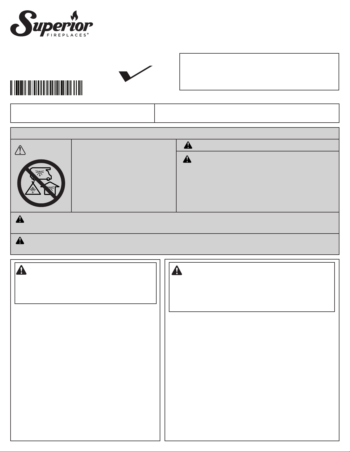
When Planning for the installation of the fireplace, the framing height must be increased
from 46-1/2" to 47-1/4", when installing the
drain pan. An additional space below the
fireplace will also be required to plumb a
drain line.
Step 1. Seal all joints, gaps and corners around
the bottom of the drain pan before
positioning the fireplace on its location
(Figure 2).
Step 2. On the exposed drain hole, install a PVC
threaded coupling reducer, 3/4" x 1/2"
going from the top of the pan down
through the hole. Apply a siliconebased sealant around the base and
threads before installation.
Step 3. Holding the reducer coupling with a
wrench, thread a 3/4", 90 degree, PVC
elbow to the reducer until it is tight to
the metal.
Step 4. Add additional piping to route the drain
to an appropriate location.
Threaded
Reducer
3/4 x 1/2
(PVC)
Drain Connector Detail
47 1/4
Threaded
Elbow 3/4
@ 90
º
(PVC)
NOTE: To assure proper drainage, the fireplace
must be installed on a leveled surface.
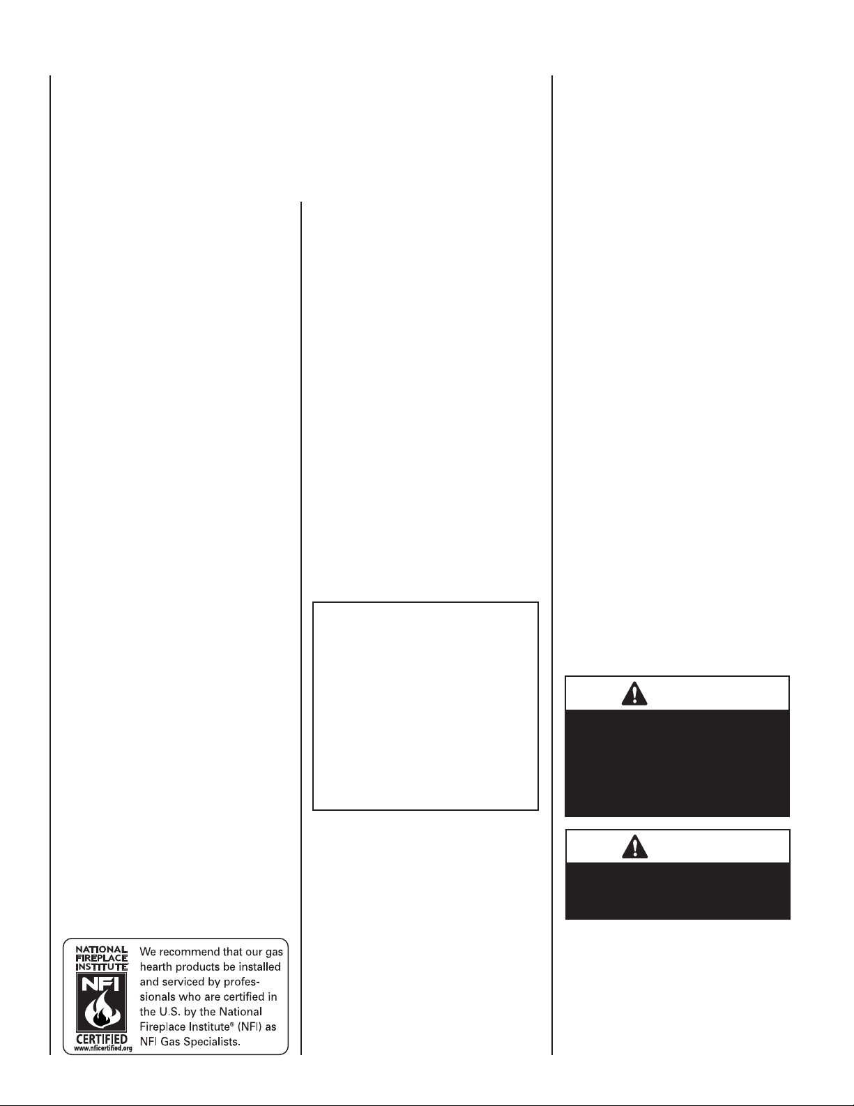
CLEARANCES
Minimum clearance to combustibles for the
fireplace is as follows; sides and back – 1/2"
(13mm), combustible floor – 0" (0mm), adjacent wall 6" (152mm), ceiling – 72" (1829mm).
Refer to Figure 3 on this Page and Figure 24
on Page 15 for more detail.
NOTE: Clearance behind the nailing flange
for both fireplace models is 1/2" (13mm).
NOTE: Adjacent wall considerations are for
an adjacent wall to only a single side. Walls
should not be placed at the minimum distance
on both sides of the fireplace. Allow at least
4 feet on one side of the fireplace.
Mantel Clearances
See Page 9.
Figure 2
Figure 3
5
NOTE: DIAGRAMS & ILLUSTRATIONS ARE NOT TO SCALE.
Page 6
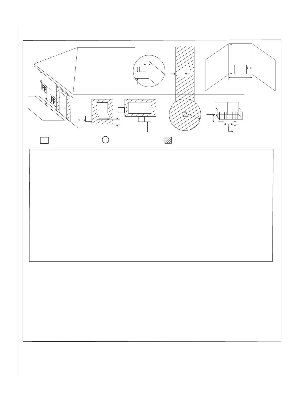
CLEARANCE SPECIFICATIONS
FP
= FIREPLACE OPENING
X
= AIR SUPPLY INLET
= AREA WHERE FIREPLACE IS NOT PERMITTED
FP
(See Note 2)
D
L
A
H
M
X
J or K
I
G
F
FP
FP
FP
FP
FP
B
B
B
A = 2 in. . . . . . . . . . clearances above grade,
veranda, porch, deck or
balcony.
B = 12 in. . . . . . . . . . clearances to window or door
that may be opened, or to
permanently closed window.
36 in. . . . . . . . . . vinyl windows or siding.
D = 47 in. . . . . . . . . . vertical clearance to unventi-
lated soffit or to ventilated soffit
located above the fireplace.
60 in. . . . . . . . . . vinyl clad soffits.
F = 9 in. . . . . . . . . . clearance to outside corner.
G = 6 in. . . . . . . . . . clearance to inside corner.
48 in. . . . . . . . . . vinyl windows or siding.
H = 3 ft. (Canada). not to be installed above a gas
meter/regulator assembly within
3 ft (914 mm) horizontally from
the center line of the regulator.
I = 3 ft. (USA)
6 ft. (Canada)
clearance to service regulator
vent outlet and electric service.
J = 9 in. (USA)
12 in. (Canada)
clearance to non-mechanical air
supply inlet to building or the
combustion air inlet to any other
appliance.
K = 3 ft. (USA)
6 ft. (Canada)
clearance to a mechanical air
supply inlet.
L* = 54 in. . . . . . . . . . clearance above paved sidewalk
(See note 1) or a paved driveway located on
public property.
M** = 47 in. . . . . . . . . . clearance under veranda, porch,
deck, balcony or overhang.
Not allowed: . . . . . . vinyl.
P = 92 in.
* A fireplace shall not open directly above a sidewalk or paved
driveway which is located between two single family dwellings
and services both dwellings.
* * Only permitted if veranda, porch, deck or balcony is fully open
on a minimum of 2 sides beneath the floor, or if the screened
porch guidelines are followed.
Note 1: Local codes or regulations may require different clearances.
Note 2: Fireplaces
in an alcove space (spaces open only on one
side and with an overhang) are permitted with the dimensions
specified for vinyl or non-vinyl siding and soffits. 1) There must
be a 3 ft minimum between terminations or between the
fireplace and termination. 2) All mechanical air intakes within
10 ft of the top of the fireplace opening must be a minimum of
3 ft below the top of the fireplace opening.
3)
All gravity air intakes within 3 ft of the fireplace must
be a minimum of 1 ft below the face top opening.
This fireplace is approved for installation in screened porches with the
following guidelines:
Minimum porch area - 96 sq ft
Minimum ceiling height - 92 in.
Minimum of two walls must be screened or open
Minimum top of screen height, side walls - 6 ft 8 in.
Minimum screen area - 64 sq ft
Note: There may be some odor and small amounts of soot associated
with burning the fireplace in a screened porch. Ensuring good cross
draft ventilation and routine maintenance of the fireplace will maximize
comfort and cleanliness.
. . . .
. . . .
Q = 72
in.
C = 72 in. . . . . . . . . . clearance below an
opperable window.
.
. . . .
C
P
G
Q
A
Figure 4
6
NOTE: DIAGRAMS & ILLUSTRATIONS ARE NOT TO SCALE.
Page 7
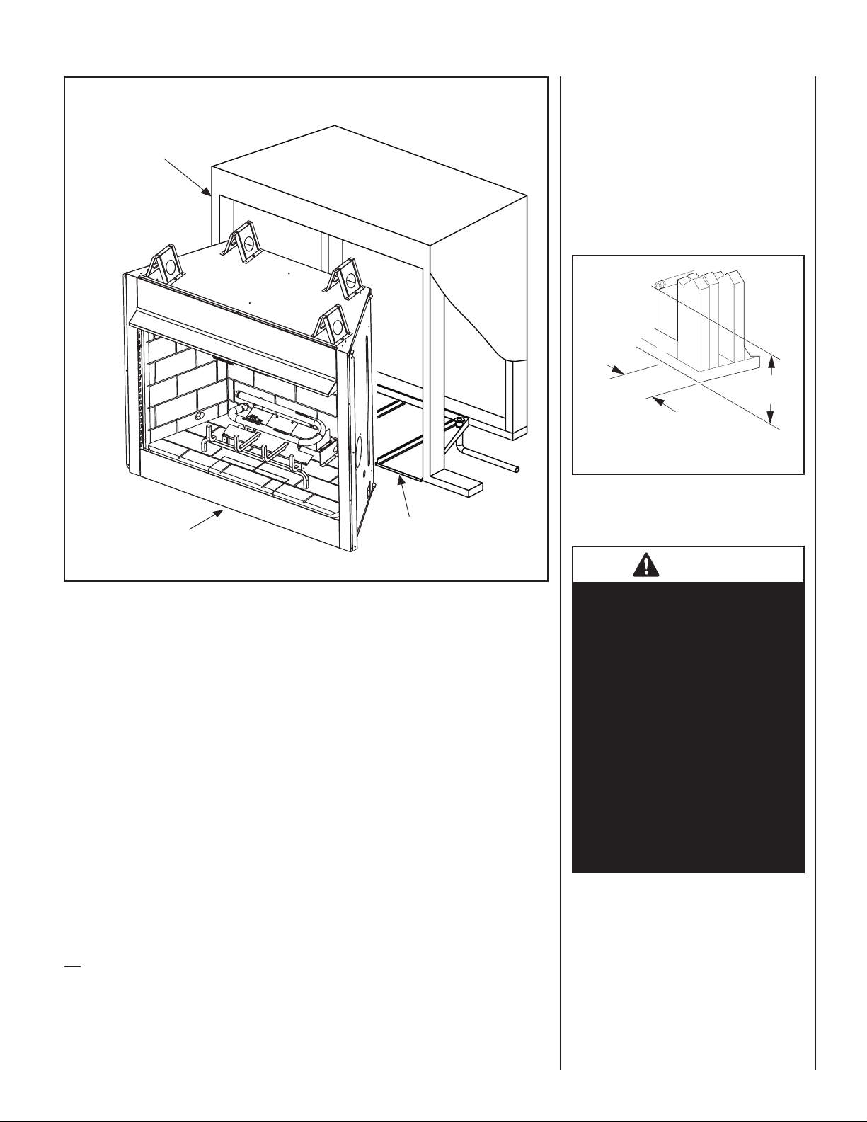
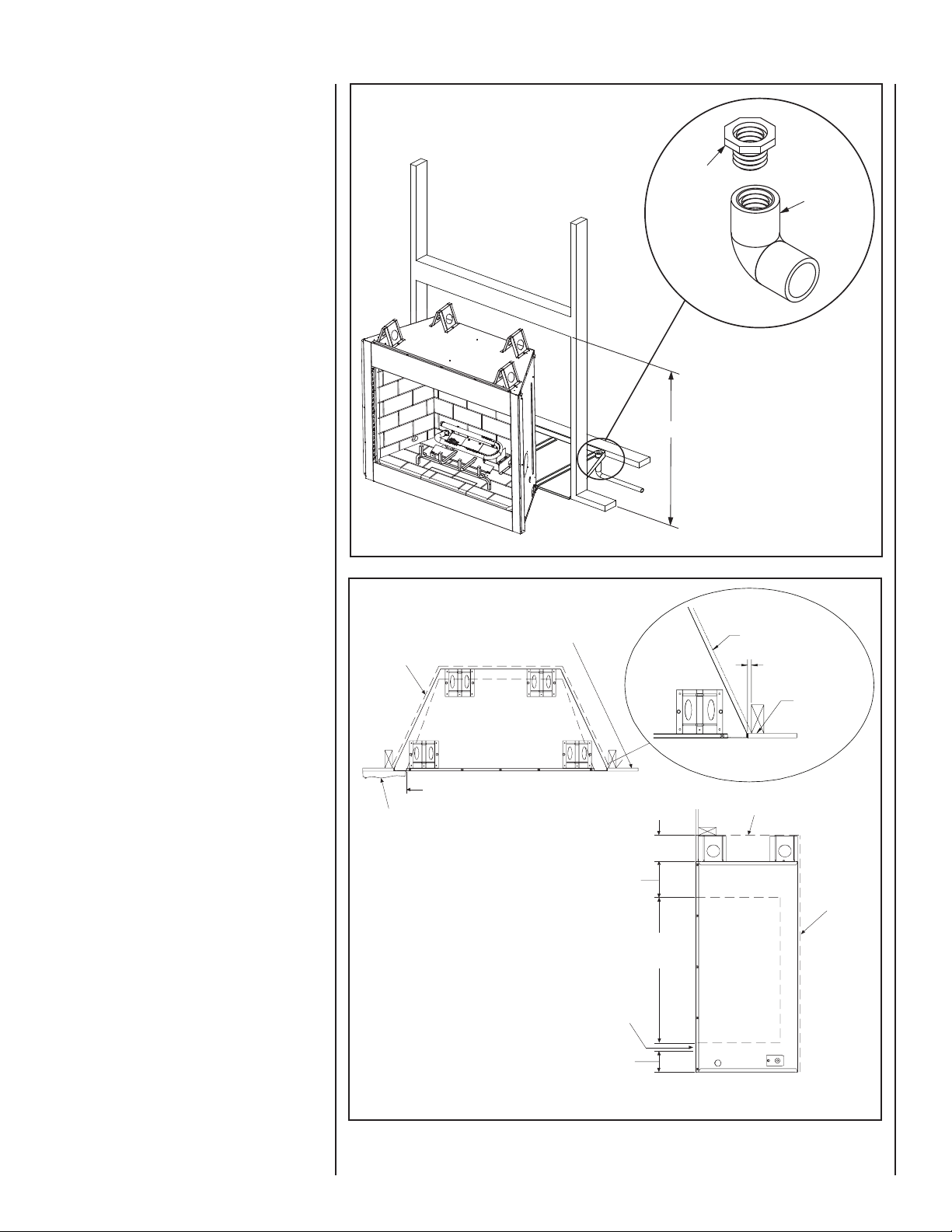
Right Side
Front Corner
Of Fireplace
Framing
3-3/4"
(95 mm)
1-3/4"
(44 mm)
Weatherproof
TYPICAL INSTALLATION
Enclosure
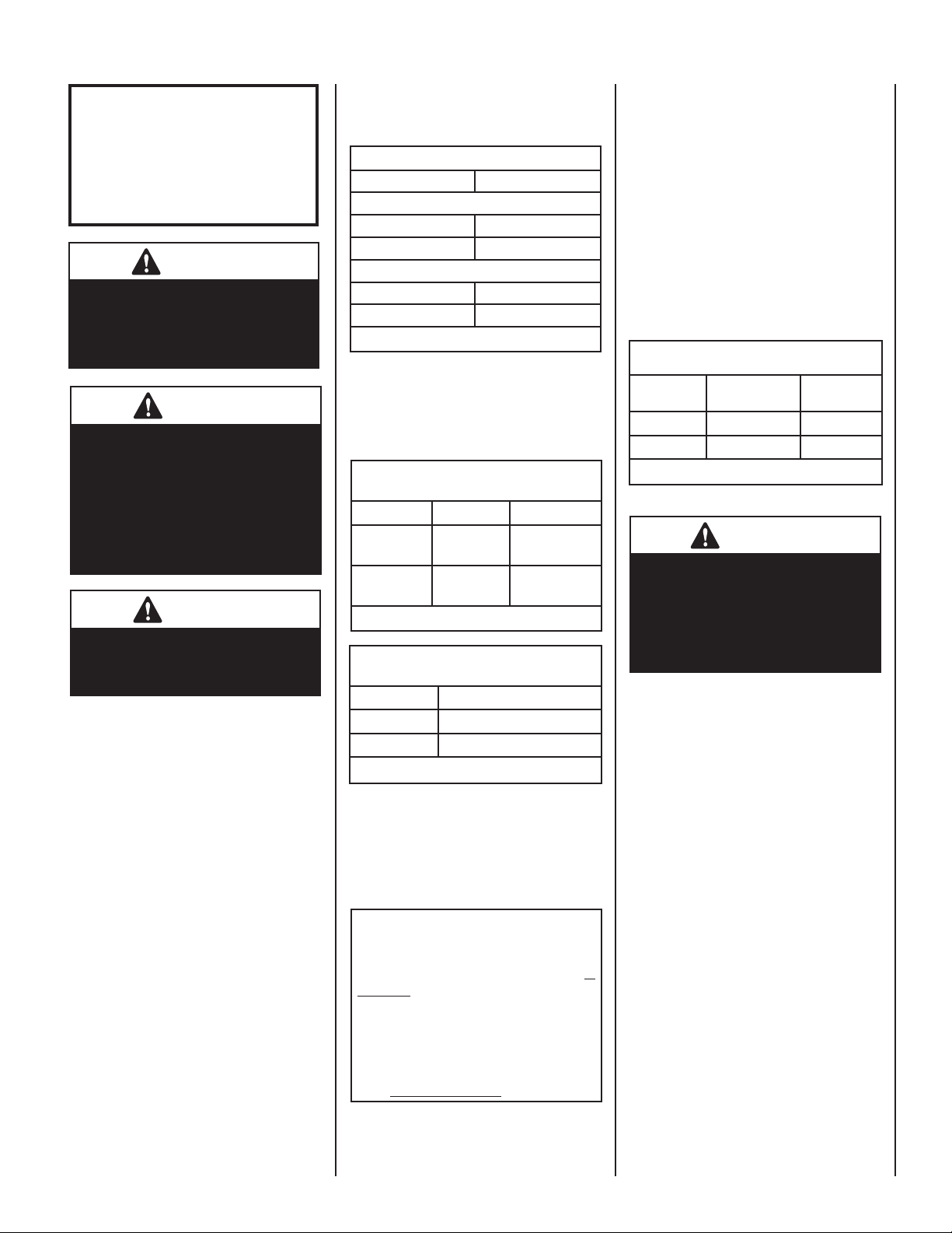
ROUTING GAS LINE
Route a 1/2" (13 mm) gas line along the inside
of the right side framing as shown in Figure 5.
Gas lines must be routed, constructed and made
of materials that are in strict accordance with
local codes and regulations.
All appliances are factory-equipped with a
flexible gas line connector and 1/2" shutoff
valve. (See Figure 12, Page 10).
Figure 6
FIREPLACE INSTALLATION
Step 1. Frame these appliances as illustrated in
Figures 8-10, Page 9. All framing details must
allow for a minimum clearance to combustible
framing members, as shown in Figure 3, Page
5. Also refer to Fireplace Specifications on Page
8. Headers may be in direct contact with the
appliance top spacers but must not be supported by them or notched to fit around them.
All construction above the appliance must be
self supporting. DO NOT USE THE APPLIANCE
FOR STRUCTURAL SUPPORT.
NOTE: The framed depth from a framed wall,
must always be measured from a finished
surface. If a wall covering such as Durock® is
to be attached to the rear wall, then the depth
must be measured from the wall surface. It
is important that this dimension be exact.
Figure 5
Fireplace
Optional Drain Pan
Step 2. Level the firebox by checking the top
edge of the firebox. Shim if necessary.
Step 3. The fireplace should be secured to the
side framing members, using the full length
nailing flange located on both sides of the
fireplace. Use 8d nails, or screws.
IMPORTANT: UNDER NO CIRCUMSTANCES
SHALL THE FIREBOX TOP SPACERS BE REMOVED OR MODIFIED. THE HEADER MAY BE
IN DIRECT CONTACT WITH THE TOP SPACERS
BUT MUST NOT BE SUPPORTED BY THEM OR
NOTCHED TO FIT AROUND THEM.
NOTE: An additional inlet has been provided
on the left side (see Figure 7, Page 8).
CAUTION
If propane is used, be aware
that with a tank that is too
small (i.e., under 100 lbs, if
this is the only gas appliance
in the dwelling—see NPFA
58), there may be a loss of
pressure. This can result in
insufficient fuel delivery that
can cause sooting, delayed
ignition, or other malfunctions.
Any damage resulting from
an improper installation is
not covered by the limited
warranty.
NOTE: Non-combustible framing members are
not required, but are recommended.
7
NOTE: DIAGRAMS & ILLUSTRATIONS ARE NOT TO SCALE.
Page 8
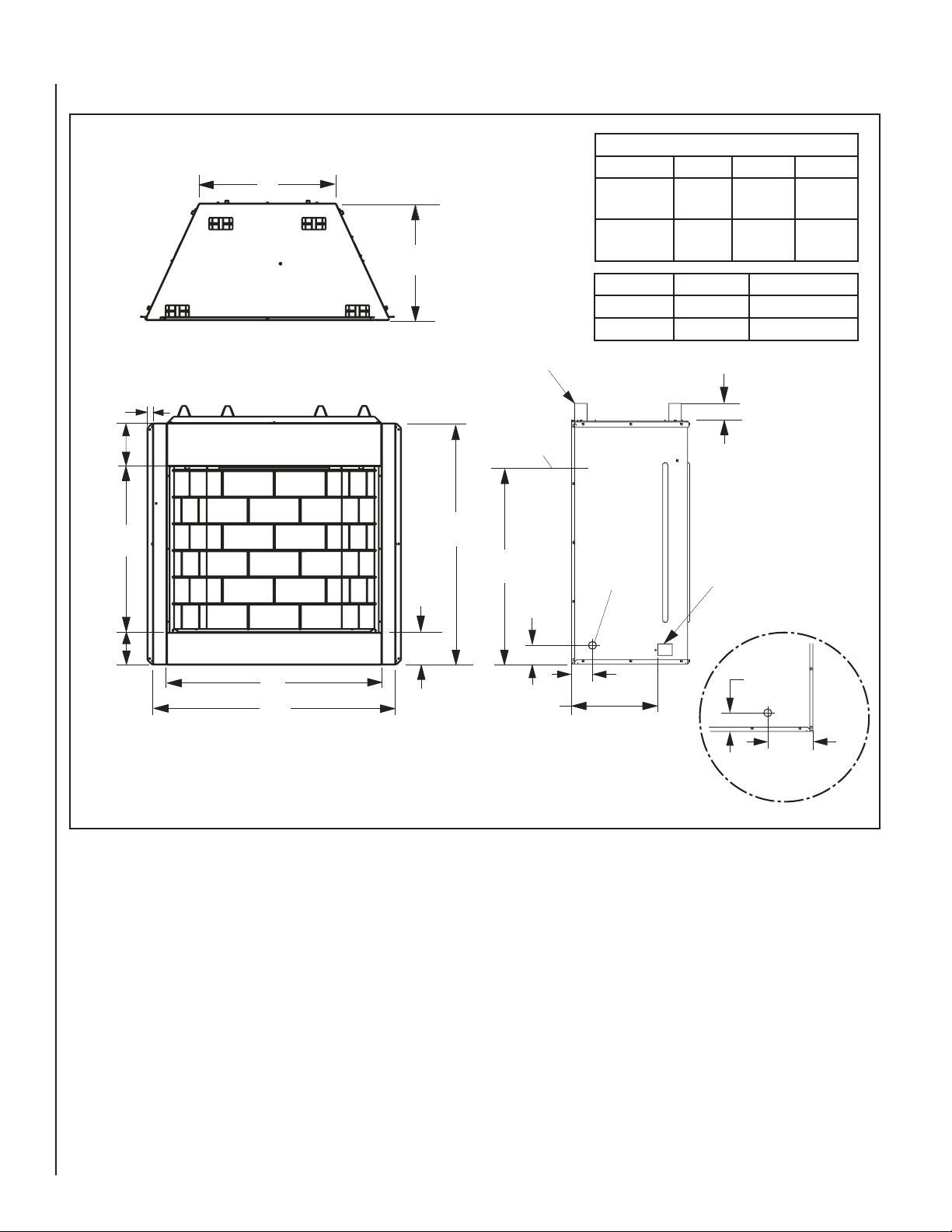
FIREPLACE SPECIFICATIONS
Gas Line
Access (Both Sides)
Access Opening for
Umbilical Cord -
Right Side Only
Top View
A
C
B
1 (25)
7-1/8
(181)
Front View
Right Side View
Top Stand-Off
Spacers
(4 places)
5-3/4
(146)
5-3/4
(146)
To p of Firebox
Opening
Bottom of
Firebox
Opening
Dimensions - Inches (millimeters)
Model No.A BC
37
(940)
41-3/4
(1061)
23-1/2
(597)
43
(1092)
47-3/4
(1213)
29-1/2
(749)
1-3/4
28-1/2
(724)
41-3/8
(1051)
34-1/4
(870)
5
(127)
20
(508)
12
(305)
4-3/8
(111)
Left Side Gas Inlet
8-1/4
(210)
2
(51)
Model
Ship. Weight (lbs)
Shipping Volume
230 lbs
38 Cu. Ft.
Weight And Volume
200 lbs
35 Cu. Ft.
Polaris36
Polaris42
Polaris36
Polaris42
Dimensions - Inches (millimeters)
Model A B C
VRE3236
VRE3242
37
(940)
43
(1092)
41-3/4
(1061)
47-3/4
(1213)
23-1/2
(597)
29-1/2
(749)
Model Ship. Wt. Shipping Volume
VRE3236
VRE3242
260 lbs
290 lbs
28.424 Cu. Ft.
32.184 Cu. Ft.
Figure 7
8
NOTE: DIAGRAMS & ILLUSTRATIONS ARE NOT TO SCALE.
Page 9
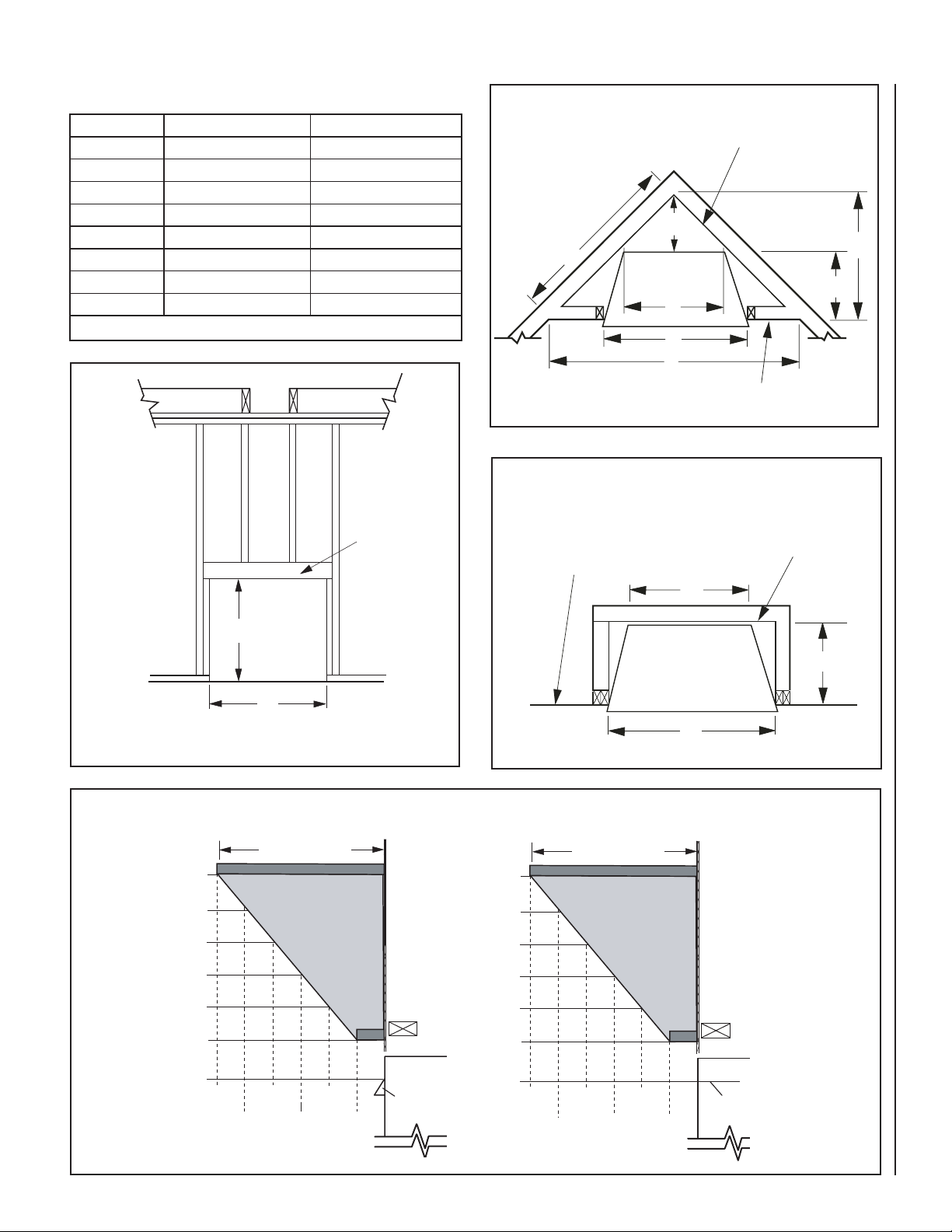
FRAMING SPECIFICATIONS
Corner
Installation
A
C
D
H
F
G
E
Back Wall Of
Chase/Enclosure
Including Finishing
Materials If Any
Rough Framing Face
(Unfinished Shown)
C
G
A
Parallel Installation
Rough Framing Face
(Unfinished Shown)
Back Wall Of
Chase/Enclosure
Including Finished
Materials - If Any
Opening VRE3236 VRE3242
A
B
C
D
E
F
G
H
Table 5 - This Table Corresponds To Figures 8, 9 and 10
42-3/4" (1086) 48-3/4" (1238)
46-1/2" (1181) 46-1/2" (1181)
23-5/8" (600) 29-5/8" (753)
11-1/4" (286) 14-1/4" (362)
63-1/2" (1613) 69-1/2" (1765)
31-3/4" (807) 34-3/4" (883)
20-1/2"( 521) 20-1/2"( 521)
44-1/4" (1124) 49-1/8" (1248)
Header
Figure 9
*Increase Framing Height by 34" when using an Optional Drain Pan
Figure 8
Figure 11
19 (483)
17 (432)
15 (381)
13 (330)
11 (280)
9 (229)
B*
A
Mantel depth
INSTALLED
12
(305)
8
(203)
10
(254)
6
(152)
WITH
HOOD
4
(102)
Figure 10
Mantel Clearances
23 (585)
21 (534)
19 (483)
17 (432)
15 (381)
13 (330)
Fireplace
Hood
2
(51)
NOTE: DIAGRAMS & ILLUSTRATIONS ARE NOT TO SCALE.
12
(305)
Mantel depth
8
(203)
10
(254)
WITHOUT
HOOD
INSTALLED
4
(102)
6
(152)
2
(51)
inches (millimeters)
Fireplace
Top of Firebox
Opening
9
Page 10

Gas Flex Line Connector
Gas
Stub
1/2" x 3/8" Flare
Shut-Off Valve
3/8" Flex Tubing
3/8" NPT x 3/8"
Flare Fitting
3/8" Nipple
3/8" Union
3/8" Close Nipple
3/8" Shut-Off Valve
1/2" x 3/8"
Reducer
Gas
Valve
10
FIELD WIRING
CAUTION: LABEL ALL WIRES PRIOR TO DISCONNECTION WHEN SERVICING CONTROLS.
WIRING ERRORS CAN CAUSE IMPROPER AND
DANGEROUS OPERATION. VERIFY PROPER
OPERATION AFTER SERVICING.
Refer to Figure 32, Page 24 for the wiring
schematic for these fireplaces. Two brown wires
are for the connection of the switch. These are
labeled SW and SW. A black and red pair are
for connection to the battery pack. These are
labeled (+) and (–). These wires are for low
voltage current.
Wiring diagrams are provided (Figure 32, Page
24) for reference purposes only. This information
is also provided on schematics attached directly
to the appliance on a pullout panel located within
the control compartment.
CONNECTING GAS LINE
Codes require a shut-off valve mounted in the
supply line. Figure 12 illustrates two methods for
connecting the gas supply. The flex-line method
is acceptable in the U.S., however, Canadian
requirements vary depending on locality. Installation must be in compliance with local codes.
These appliances are equipped with a gas flex
line for use (where permitted) in connecting the
unit to the gas line. A gas flex line is provided to
aid in attaching the outdoor appliance to the gas
supply. The gas flex line can only be used where
local codes permit. See Figure 12 for flex line
description. The flex line is rated for both natural
and propane gas. A manual shut off valve is also
provided with the flex line.
The gas control valve is located under the refractory cover in front of the burner.
To access the valve, lift out the center refractory
and remove the rain shield (see Figure 13).
The control valves have a 3/8" (10 mm) NPT
thread inlet port.
Secure all joints tightly using appropriate
tools and sealing compounds (ensure propane
resistant compounds are used in propane applications).
Turn on gas supply and test for gas leaks, using a
gas leak test solution (also referred to as bubble
leak solution). NOTE: Using a soapy water solution (50% dish soap, 50% water) is an effective
leak test solution but it is not recommended,
because the soap residue that is left on the pies/
fittings can result in corrosion over time. Never
use an open flame to check for leaks.
A. Light the appliance (refer to the lighting in-
structions label in the control compartment
or in the Care and Operation Instructions).
B. Brush all joints and connections with the gas
leak test solution to check for leaks. If bubbles
are formed, or gas odor is detected, turn the
gas control knob to the “OFF” position. Either
tighten or refasten the leaking connection and
retest as described above.
C. When the gas lines are tested and leak free,
be sure to rinse off the leak testing solution.
Figure 12 - Gas Connection
Figure 13 - Valve Access
Gas Shutoff
Valve
1/2" NPT Incoming
Gas Line
NOTE:
1) Wire connections not shown for clarity
2) * 1/8" NPT Plugged Tapping
Figure 14 - Connecting Incoming Gas Line to Flex Gas Line
NOTE: DIAGRAMS & ILLUSTRATIONS ARE NOT TO SCALE.
Flexible Gas Line Do
NOT Kink
Inlet Pressure Tap
IN
PILOTADJ
Outlet Pressure Tap
Pilot Adjustment
MAIN
PILOT
OUT
Set Screw
Page 11

Install the Logs and Glowing Embers
WARNING
• Turn OFF all gas and electricity to the appliance before installing the embers, and logs.
• Do NOT install the logs until the appliance has been completely installed, the gas line connected and
tested for leaks, and the initial burner operation has been confirmed.
• Use of an unapproved log set in the fireplace will void the warranty and will result in incomplete
combustion, sooting, and poor flame quality.
• Logs get very hot and will remain hot up to one hour after gas supply is turned off. Handle only when
logs are cool. Turn off all electricity to the appliance before you install grate and logs.
• This appliance is not designed to burn wood. Any attempt to do so could cause irreparable damage to
appliance and prove hazardous.
• If the logs are not installed according to these instructions, improper combustion could occur. This
could result in the excessive production of soot and/or the colorless, odorless, toxic gas carbon
monoxide (CO).
• The size and position of the log set was engineered to give your appliance a safe, reliable and
attractive flame pattern. Any attempt to use a different log set in the fireplace will void the warranty
and will result in incomplete combustion, sooting, and poor flame quality.
NOTE: It is important to ensure proper log placement per the manual when installing these units. Verify pilot flame is not
obstructed. See Verifying Appliance Operation on Page 42.
NOTE: DIAGRAMS & ILLUSTRATIONS ARE NOT TO SCALE.
11
Page 12

Installing the VRE3200 Series Log Set
The logs have notches/tabs to assist proper positioning. Upper logs rest on lower logs via notches/tabs. Proper log placement
is critical to prevent sooting. Place the logs in the gaps between flame peaks, so they do not impinge the flames. Follow the log
placement instructions precisely. NOTE: Do not cover the burner ports.
Table 6 - Log Set
I.D.
No.
1 Rear Log
2 Middle Log
3 Right Front Log
4 Front Left Log
5 Top Right Log
6 Middle Twig Log
7 Top Rear Log
8 Top Left Log
1. Place rear log (1) being pilot in-between the tube burner. (Figure 15)
2. Place middle log (2) directly in front of tube burner (Figure 16).
Description
1
5
2
8
4
3
6
7
8
7
4
1
2
5
6
3
1
2
Square Protrusion
for Log 7
Pin for Log 7
Figure 15 - Place Rear Log (1)
1
Round Protrusion
for Log 5
Front View Front View
Square Protrusion
for Log 8
Figure 16 - Place Middle Log (2)
3. Place front right log (3) onto grate. The notch on the "charred section" will fit around the grate(Figure 17).
4. Place front left log (4) onto grate. The notch on the "charred section" will fit around the grate (Figure 18).
1
2
2
3
4
Square Protrusion
for Log 5
1
3
12
Figure 17 - Place Front Right Log (3)
Top
View
Figure 18 - Place Front Left Log (4)
NOTE: DIAGRAMS & ILLUSTRATIONS ARE NOT TO SCALE.
Top
View
Page 13

Installing the VRE3200 Series Log Set (continued)
5. Position top right log (5) using the round protrusion on the rear log (1) and the square protrusion on the middle log (2) (Figure 19).
6. Position middle twig log (6) using the pin on top right log (5) (Figure 20).
5
6
3
Top View
Cut-out fits over
protrusion on Log 1
(See Figure 15)
4
Cut-out fits over
protrusion on Log 2
(See Figure 16)
Bottom View
1
2
3
Top View
5
Pin for Log 6
4
Bottom View
1
2
Fits ove Pin on Log 5
(see Figure 19)
Figure 19 - Place Top Right Log (5) Figure 20 - Place Middle Twig Log (6)
7. Position top rear log (7) over the square protrusion and pin on the rear log (See Figure 15 and G).
8. Position Top Left log (8) onto the landings on the top rear log (7) (Figure 21) and the protrusion on the middle log (2) (Figure 22).
Landing for Log 8
5
8
7
1
5
Protrusion
for Log 8
7
1
Notch fits over
pin on Log 1
4
Cut-out fits over
protrusion on Log 1
Bottom View
2
6
Top View
2
3
4
Cut-out fits over
protrusion on Log 2
(see Figure 16)
Bottom View
Figure 21 - Place Top Rear Log (7) Figure 22 - Place Top Left Log (8)
NOTE: DIAGRAMS & ILLUSTRATIONS ARE NOT TO SCALE.
6
3
Top View
13
Page 14

FLAME APPEARANCE AND SOOTING
Sooting is indicated by black puffs developing
at the tips of very long orange flames. Sooting
results in black deposits forming on the logs,
appliance inside surfaces and on exterior surfaces adjacent to the face opening.
These appliances should not smoke. Small
amounts of soot will accumulate over time
and should be expected. This soot adds to the
realism of the firebox interior. The logs can be
cleaned, when cool, with a soft brush and small
amounts of water.
Keep in mind that this is an outdoor appliance. Wind and air currents cannot be strictly
controlled.
If the flame acts too erratically, we recommend
that the screens be closed.
Figure 23 - Proper Burner Flame Appearance
14
NOTE: DIAGRAMS & ILLUSTRATIONS ARE NOT TO SCALE.
Page 15

CHECKING APPLIANCE OPERATION
must be non-combustible materials.
With gas line installed run initial system checkout before installing any additional accessories.
Follow the lighting instructions on Page 21.
NOTE: Lighting Instructions are also found
on the literature tag tied to the gas piping
next to the gas valve. To access the tag,
open the lower control compartment door
(refer to Figure 13, Page 10 - Valve Access).
When first lighting the appliance, it will take a few
minutes for the line to purge itself of air. Once
purging is complete, the burner will light and
operate as indicated in the instruction manual.
Subsequent lighting of the appliance will not
require such purging. Inspect the pilot flame
(remove logs, if necessary, handling carefully).
After the logs have been placed and the fireplace
has been checked for proper flame presentation.
Electronic Appliance Checkout
Carbon Monoxide Poisoning: Early signs
of carbon monoxide poisoning are similar
to the flu with headaches, dizziness and/
or nausea. If you have these signs, obtain
fresh air immediately. Turn off the gas supply to the appliance and have it serviced by
a qualified professional, as it may not be
operating correctly.
FIREBOX FINISHES
Only noncombustible materials like marble,
stone, tile, brick, etc. may overlap the top and
sides of the front facing. Seal all joints between
the black facing and wall surrounds to prevent
air intrusion.
6 (153) Minimum
For Combustible
Materials
See Note
Use noncombustible caulking materials only to
seal the metal facing to the surround material
on the finished wall. See Figure 24.
CAUTION: DO NOT BLOCK THE FACE OPENING ON THESE FIREBOXES. DOING SO MAY
CREATE A POTENTIAL FIRE HAZARD.
Mantel
Review mantel clearances
Figure 11, Page 9
3-3/4 (95)
Max.
NOTE: The area above the face to the top of the spacers
Figure 24 - Clearances To Combustibles
15
NOTE: DIAGRAMS & ILLUSTRATIONS ARE NOT TO SCALE.
Page 16

GAS CONVERSION KITS
Gas conversion kits are available to adapt your
appliance from the use of one type of gas to
the use of another. These kits contain all the
necessary components needed to complete the
task including labeling that must be affixed to
ensure safe operation.
Kit part numbers are listed here:
Natural to Propane Gas Conversion Kits
Cat. # Model Fireplace
F4126 CKAF4004SLLXNP VRE32 36/42
Propane to Natural Gas Conversion Kits
Cat. # Model Fireplace
F4127 CKAF4004SLLXPN VRE32 36/42
Table 7
See the following Table for orifice sizes for
natural and propane models. Figure 26 illustrates the orifice. Use pipe joint compound or
Teflon tape on all pipe fittings before installing
(ensure propane resistant compounds are used
in propane applications, do not use pipe joint
compounds on flare fittings).
Burner Orifice Sizes
Elevation 0-4500 feet ( 0-1372 meters)
Model
VRE3236 3.25mm (.128") #49 (.073")
VRE3242 3.25mm (.128") #49 (.073")
Nat.Gas
drill size (inches)
Propane
drill size (inches)
Table 8
WARNING
This conversion kit shall be installed by a qualified service agency in
accordance with the manufacturer’s instructions and all applicable codes
and requirements of the authority having jurisdiction. If the information in
these instruction is not followed exactly, a fire, explosion or production of
carbon monoxide may result causing property damage, personal injury
or loss of life. The qualified service agency is responsible for the proper
installation of this kit. The installation is not proper and complete until the
operation of the converted appliance is checked as specified in the manufacturer’s instructions supplied with the kit. The qualified service agency
performing this installation assumes responsibility for this conversion.
AVERTISSEMENT
Cette trousse de conversion doit être installée par un technicien agréé,
selon les instructions du fabricant et selon toutes les exigences et tous les
codes pertinents de l’autorité compétente. Assurez-vous de bien suivre
les instructions dans cette notice pour réduire au minimum le risque
d’incendie, d’explosion ou la production de monoxyde de carbone pouvant
causer des dommages matériels, des blessures ou la mort. Le tecnicien
agréé est responsable de l’installation de cette trousse. L’installation n’est
pas adéquate ni complète tant que le bon fonctionnement de l’appareil
converti n’a pas été vérifié selon les instructions du fabricant fournies avec
la trousse. Le fournisseur de service qualifié ayant réalisé l'installation
assume les responsabilités liées à la conversion.
In Canada:
THE CONVERSION SHALL BE CARRIED OUT IN ACCORDANCE WITH THE REQUIREMENTS
OF THE PROVINCIAL AUTHORITIES HAVING JURISDICTION AND IN ACCORDANCE WITH THE
REQUIREMENTS OF THE CAN/CGA-B149.1 AND .2 INSTALLATION CODE.
LA CONVERSION DEVRA ÊTRE EFFECTUÉE CONFORMÉMENT AUX RECOMMANDATIONS DES
AUTORITÉS PROVINCIALES AYANT JURIDICTION ET CONFORMÉMENT AUX EXIGENCES DU
CODE D'INSTALLATION CAN/CGA-B149.1 ET .2.
16
Figure 26
NOTE: DIAGRAMS & ILLUSTRATIONS ARE NOT TO SCALE.
Page 17

OPERATION AND CARE OF YOUR
APPLIANCE
Appliance operation may be controlled by a
remotely located wall switch.
Gas Controls/Control Compartment Access
The gas controls can be found beneath the
bottom refractory. Remove the bottom refractory by lifting it up. Remove the access cover
(refer to Figure 27).
Note: Adjustment screws are provided to level
refractory access cover (refer to Figure 27a).
All Models -
To light these appliances refer to the detailed
lighting instructions found on Page 21. The
appliance lighting instructions may also
be found on the pull out lighting instruction
labels attached to the gas control valve (see
Figure 27).
WARNING
FAILURE TO COMPLY WITH THE INSTALLATION AND OPERATING INSTRUCTIONS PROVIDED IN THIS DOCUMENT
WILL RESULT IN AN IMPROPERLY INSTALLED AND OPERATING APPLIANCE,
VOIDING ITS WARRANTY. ANY CHANGE
TO THIS APPLIANCE AND/OR ITS OPERATING CONTROLS IS DANGEROUS.
IMPROPER INSTALLATION OR USE OF
THIS APPLIANCE CAN CAUSE SERIOUS
INJURY OR DEATH FROM FIRE, BURNS,
EXPLOSION OR CARBON MONOXIDE
POISONING.
Carbon Monoxide Poisoning: Early signs
of carbon monoxide poisoning are similar
to the flu with headaches, dizziness and/
or nausea. If you have these signs, obtain
fresh air immediately. Turn off the gas supply to the appliance and have it serviced by
a qualified professional, as it may not be
operating correctly.
Figure 27 - Control Compartment Access
Refractory access cover
adjustment screws
WARNING
DO NOT PLACE CLOTHING OR OTHER
FLAMMABLE MATERIALS ON OR NEAR
THIS APPLIANCE.
AVERTISSEMENT
SURVEILLER LES ENFANTS. GARDER
LES VÊTEMENTS, LES MEUBLES,
L'ESSENCE OU AUTRES LIQUIDES À
VAPEUR INFLAMMABLES LOIN DE
L'APPAREIL.
WARNING
CHILDREN AND ADULTS SHOULD BE
ALERTED TO THE HAZARDS OF HIGH
SURFACE TEMPERATURES. USE CAUTION AROUND THE APPLIANCE TO
AVOID BURNS OR CLOTHING IGNITION. YOUNG CHILDREN SHOULD BE
CAREFULLY SUPERVISED WHEN THEY
ARE IN THE SAME ROOM AS THE APPLIANCE.
Figure 27a - Adjustment Screws
17
NOTE: DIAGRAMS & ILLUSTRATIONS ARE NOT TO SCALE.
Page 18

Variable Flame Height Adjustment
1. All appliances are equipped with a variable
gas control valve. Flame height for these
models may be adjusted from high to low
settings, alternately, while the appliance is
in operation.
Adjust the flame height as desired after
lighting the appliance by pressing high or
low on the remote control.
2. When lit for the first time, this appliance will
emit a slight odor for an hour or two. This
is due to the “burn-in” of internal paints
and lubricants used in the manufacturing
process.
3. Keep lower control compartment clean by
vacuuming or brushing at least twice a year.
More frequent cleaning may be required due
to excessive lint from carpeting, bedding
materials, etc. It is important that control
compartments, burners and circulating air
passageways of the appliance be kept clean.
S'assurer que le brùleur et le compartiment
des commandes sont propres. Voir les instructions d'installation et d'utilisation qui
accompagnent l'appareil.
4. Always keep the appliance area clear and
free from combustible materials, gasoline
and other flammable liquids.
WARNING
• Turn off gas and any electrical
power before servicing the appliance.
• Let fireplace completely cool
before cleaning.
• Failure to keep the primary
air opening(s) of the burner(s)
clean may result in sooting and
property damage.
• Burner Flame Pattern - If yellow
tipping occurs, your fireplace
could produce increased levels
of carbon monoxide. Do not
mistake orange flames with
yellow tipping. Dirt or other fine
particles enter the fireplace and
burn causing brief patches of
orange flame.
Verify proper operation after servicing.
S'assurer que l'appareil fonctionne
adéquatement une fois l'entretien
terminé.
IGNITER ASSEMBLY
The igniter assembly is factory preset for
proper ignition of the burner. Alterations may
have occurred during shipping and handling.
Call a qualified service person to readjust the
igniter assembly if necessary.
The igniter should be positioned as shown in
Figure 28.
NOTE: Figure 28, shows the correct positioning
of the igniter and sensing rod.
If your igniter assembly does not meet these
requirements:
• Turn appliance off (see To Turn Off Gas to
Appliance, Page 21).
• See Troubleshooting, Page 22.
Sensing Rod
Igniter
Cleaning and Maintenance
The appliance should be thoroughly inspected
before initial use and at least annually by a qualified service technician. However, more frequent
periodic inspections and cleanings should be
performed by the homeowner. Homeowner
must contact a qualified service technician at
once if any abnormal condition is observed.
Refer to the maintenance schedule (Page 24) for
maintenance tasks, procedures, periodicity and
by whom they should be performed. Always verify
proper operation of the appliance after servicing.
NOTE: Make sure you have new batteries.
CAUTION
You must keep control areas,
burner and circulating air passageways of fireplace clean.
Inspect these areas of fireplace
before each use. Have fireplace
inspected yearly by a qualified
service person.
Inspect Burner Flame and Pilot Flame
Appearance
Periodically do a visual check of the burner
flame and the pilot flame. Ensure that the burner
flame appearance resembles the flame shown in
Figure 23, Page 14 and as described in Flame
Appearance and Sooting on Page 14.
Battery Replacement
NOTE: All batteries loose voltage when frozen
or left for prolonged periods. It may be wise
to remove batteries during extended periods
of disuse.
Inspect Burner Assembly
If it is evident that the burner is damaged, the
burner must be replaced with one specified by
the manufacturer before the appliance is put
into operation.
Igniter
Burner
Tube
Figure 28 - Igniter Assembly
18
NOTE: DIAGRAMS & ILLUSTRATIONS ARE NOT TO SCALE.
Page 19

GAS CONTROL MODULE SYSTEM
REMOTE CONTROL FEATURE
The module has a built in remote control receiver that allows the user
to program the remote transmitter at any time during or after the installation of the burner.
1. There is a switch located on the right side of the module that reads
REMOTE/OFF (Figure 29).
2. When the remote/off switch is in the OFF position, the burner will
operate from the rocker switch or wall switch connected to the two
BROWN wires on the module.
3. When the remote/off is in the REMOTE position the burner will operate
from the Remote Control Transmitter.
NOTE: The module must be programmed to the Remote Control Trans-
mitter.
• To program the module (make sure the system has power), locate
the learn button (Figure 30) on the module. Locate the metal shield
that is covering the module and remove the screw on top. Use a
small thin object like a paper clip (not sharp points) to press and
release the learn button. There will be a beep sound from the module.
Then press any button on the remote transmitter. Once the module's
internal receiver accepts the transmitter code, there will be a series
of confirming beeps.
• The remote system is ready for use.
• Pushing and holding the LEARN button for 6 seconds will result in
clearing the transmitter security code from the module's memory.
The module will make three long beeps in succession when it has
been cleared.
REMOTE CONTROL "DRY-OUT" FEATURE
The remote/Ignitor has a special feature. It will allow heat from the burner
to dry the probe and burner assembly due to excess moisture, caused
by rain, humidity or condensation. To activate:
• Press and hold the HI and LO buttons on the transmitter for 30-45
seconds. This allows the sparking to start and the burner to ignite.
• Release the HI and LO buttons, after the allotted time, sparking will
stop and the burner will go out.
• Press and hold the ON button and sparking will start again and
burner should ignite.
• Release the ON button. The sparking will stop, and the burner
should stay ON.
• Repeat if necessary.
Learn Button
Figure 30 - Gas Module Left Side
AUX Connection
REPLACEMENT PARTS
NOTE: Use only original replacement parts. This will protect your
warranty coverage for parts replaced under warranty.
Normally, all parts should be ordered through your IHP distributor
or dealer. Parts will be shipped at prevailing prices at time of order.
NEVER USE SUBSTITUTE MATERIALS. USE OF NON-APPROVED
PARTS CAN RESULT IN POOR PERFORMANCE AND SAFETY
HAZARDS.
TECHNICAL SERVICE
You may have further questions about installation, operation, or
troubleshooting. Please contact your IHP dealer for any questions
or concerns. When contacting your dealer please have your model
and serial numbers of your appliance ready. You can also visit our
web site at SuperiorFireplaces.us.com
Remote/Off Switch
“S” Pilot Connection
Figure 29 - Gas Module Right Side
ADJ.
“I” Pilot Connection
19
NOTE: DIAGRAMS & ILLUSTRATIONS ARE NOT TO SCALE.
Page 20

ACCESSORY COMPONENTS
Drain Pan
The drain pan is used with the appliance.
Outdoor Weather Cover
This attractive stainless steel Outdoor Weather
Cover is easy to install and protects the firebox
interior from adverse weather.
Outdoor Weather Cover *
Cat. No. Model Description
F4130 WC36SL
F4131 WC42SL
36” SS Outdoor
Weather Cover
42” SS Outdoor
Weather Cover
Drain Pan
Cat. No. Model Description
H4651 DPSS36 Drain Pan (36)
H4652 DPSS42 Drain Pan (42)
Hood Kit
This attractive brushed stainless Hood Kit is
easy to install and enhances the appearance
of the appliance.
Outdoor Hood Kit
Cat. No. Model Description
F4128 Hood36ODSL
F4129 Hood42ODSL
36” Hood Kit
Outdoor Gas
42” Hood Kit
Outdoor Gas
* Cannot be used with 36/42LBFOD-BS doors in place
Decorative Volcanic Stone
The decorative volcanic stone, Model FDVS, can
be used to enhance the look of your appliance.
Order model FDVS for replacement of stone
when needed. Spread the decorative volcanic
stone evenly around the bottom ofthe firebox.
Decorative Volcanic Stone
Cat. No. Model Description
80L42 FDVS
Bag of Volcanic
Stone
Creamer Rust Cappuccino
Refractory Stain Kits
Use the Refractory Stain Kits to give white
refractory panels a new look.
Kit includes foam roller, roller handle, paint tray,
and one can of stain. Available stain colors are
Creamer (ivory), Rust (terra cotta), and Cappuccino (rosy taupe).
Refractory Stain Kits
Cat. No. Model Description
H8176 BSK-CR Creamer
H8177 BSK-RT Rust
H8178 BSK-CP Cappuccino
20
NOTE: DIAGRAMS & ILLUSTRATIONS ARE NOT TO SCALE.
Page 21

LIGHTING INSTRUCTIONS, ELECTRONIC
FOR YOUR SAFETY READ BEFORE LIGHTING
WARNING: If you do not follow these instructions exactly, a fire or explosion may result caus-
ing property damage, personal injury or loss of life.
A. This appliance does not have a pilot, it is equipped
with an ignition device which automatically lights the
pilot. Do not light pilot by hand.
B. BEFORE LIGHTING smell all around the appliance area
for gas. Be sure to smell next to the floor because some
gas is heavier than air and will settle on the floor.
WHAT TO DO IF YOU SMELL GAS
• Do not try to light any appliance.
LIGHTING INSTRUCTIONS
1. STOP! Read the safety information first.
2. Do not attempt to light the burner by hand.
3. Turn equipment shutoff valve clockwise to the OFF
position (see Figure 31). Do not force.
4. Wait five (5) minutes to clear out any gas. Then smell for
gas, including near the floor. If you smell gas, STOP! Follow “B” in the safety information. If you don't smell gas,
go to the next step.
5. Turn equipment shutoff valve counterclockwise to
the ON position. Do not force.
• Do not touch any electric switch; do not use any
phone in your building.
• Immediately call your gas supplier from a neighbor's
phone. Follow the gas supplier's instructions.
C. Do not use this appliance if any part has been under
water. Immediately call a qualified service technician
to inspect the appliance and to replace any part of the
control system and any gas control which has been
under water.
6. Push remote control ''ON'' button.
7. Visually locate igniter. Igniter should begin to spark and
main burner should ignite once flame appears at pilot.
• If lighting appliance for the first time each season, it
may take several attempts before supply gas can reach
pilot and main burners.
• If appliance will not stay lit after several attempts, follow
instructions under To Turn Off Gas To Appliance and
call your service technician or gas supplier.
TO TURN OFF GAS TO APPLIANCE
1. Push remote control ''OFF'' button.
2. Turn equipment shutoff valve clockwise to OFF. Do not force.
Incoming Gas
Line
Figure 31 - Turning Equipment Shutoff Valve to the OFF Position
Equipment Shutoff Valve
NOTE: DIAGRAMS & ILLUSTRATIONS ARE NOT TO SCALE.
PILOTADJ
IN
MAIN
PILOT
OUT
21
Page 22

TROUBLESHOOTING
WARNING: Turn off appliance and let cool before servicing. Only a qualified service person should
service and repair appliance.
NOTE: All troubleshooting items are listed in order of operation.
OBSERVED PROBLEM POSSIBLE CAUSE REMEDY
When ''ON'' button on remote control
is pressed, there is no spark at igniter
assembly
When ''ON'' button on remote control
is pressed, there is spark at igniter. but
no ignition
Delayed ignition of burner 1. Manifold pressure is too low
Burner backfiring during combustion 1. Burner orifice is clogged or damaged
Slight smoke or odor during initial
operation
Appliance produces a whistling noise
when burners are lit
1. Igniter electrode not connected to
igniter cable
2. Igniter cable pinched or wet
3. Broken igniter cable
4. Bad igniter
5. Igniter electrode positioned wrong
6. Igniter is wet
7. Igniter electrode broken
8. Battery not installed, battery power
low or battery not installed correctly
(electronic ignition models only)
1. Gas supply turned off or equipment
shutoff valve closed
2.
Air in gas lines when installed
3. Depleted gas supply (propane/LP
only)
4. Control module not in REMOTE position
5. Gas control valve pressure setting is
not correct
6. Inlet gas pressure is too low
7. Burner orifice(s) clogged
8. Wire disconnected from gas control
9. Ground wire issue
2. Burner orifice clogged
2. Damaged burner
1. Residues from manufacturing processes and logs curing
1. Air in gas line
2. Air passageways on appliance blocked
3. Dirty or partially clogged burner orifice.
1. Reconnect igniter cable
2. Free igniter cable if pinched by any metal or tubing. Keep igniter cable dry
3. Replace igniter
4. Replace igniter
5. Adjust igniter wires as shown in Figure 28 on Page
18. Replace igniter assembly if repositioning does
not correct the problem
6. See page 19 (Dry-Out Feature)
7. Replace igniter
8. Install new alkaline battery in remote control
and battery pack. Verify batteries are installed
correctly (5.4 volts batteries required to operate
valve system).
1. Turn on gas supply or open equipment shutoff
valve
2. Repeat igniting operation until air is removed
3. Contact local propane/LP gas company
4. Set control module to REMOTE position
5. Contact qualified service person to check pressure
6. Contact local natural or propane/LP gas company
7. Clean burner (see Cleaning and Maintenance,
Page 18) or replace burner orifice(s)
8.
See Wiring Diagram, Page 24
9.
Verify black ground wire from module is secured
under screw adjacent to igniter
1. Contact local natural or propane/LP gas company
2. Clean burner (see Cleaning and Maintenance,
Page 18) or replace burner orifice(s)
1. Clean burner (see Cleaning and Maintenance,
Page 18) or replace burner orifice
2. Replace damaged burner
1. Problem will stop after a few hours of operation
1. Operate burners until air is removed from line.
Have gas line checked by local natural or propane/
LP gas company
2. Observe minimum installation clearances (see Pages
5-6)
3. Clean burner (see Cleaning and Maintenance,
Page 18) or replace burner orifice(s)
22
NOTE: DIAGRAMS & ILLUSTRATIONS ARE NOT TO SCALE.
Page 23

TROUBLESHOOTING Continued
WARNING: If you smell gas
• Shut off gas supply.
• Do not try to light any appliance.
• Do not touch any electrical switch; do not use any phone in your building.
• Leave the building immediately.
• Immediately call your gas supplier from a neighbor’s phone. Follow the gas supplier’s instructions.
• If you cannot reach your gas supplier, call the fire department.
IMPORTANT: Operating appliance where impurities in air exist may create odors. Cleaning supplies, paint, paint remover, cigarette
smoke, cements and glues, new carpet or textiles, etc., create fumes. These fumes may mix with combustion air and create odors.
These odors will disappear over time.
OBSERVED PROBLEM POSSIBLE CAUSE REMEDY
White powder residue forming within
burner box or on adjacent walls or
furniture
Remote does not function 1. Battery is not installed. Battery power
Appliance produces a clicking/ticking noise just after burners are lit or
shut off
Appliance produces unwanted odors 1. Appliance burning vapors from paint, hair
Appliance shuts off in use 1. Low line pressure 1. Contact local natural or propane/LP gas company
Gas odor even when control knob is
in OFF position
Module makes 4 beeps every 2
seconds
Module makes one beep every one
second
Gas odor during combustion
1. When heated, vapors from furniture
polish, wax, carpet cleaners, etc. may
turn into white powder residue
is low
1. Metal expanding while heating or
contracting while cooling
2. Igniter Assembly is out of position
3. Wind is disturbing the burner flame
and the igniter assembly is relighting
the burner
4. Wire connection loose or wire broken
spray, glues, cleaners, chemicals, new
carpet, etc. (See IMPORTANT statement
above)
2. Low fuel supply (propane/LP only)
3. Gas leak. See Warning statement at
top of Page
1. Gas leak. See Warning statement at
top of Page
2. Control valve or gas control defective
1. The module's internal temperature is
too high
1. The burner did not successfully ignite 1. Press OFF then ON buttons to re-attempt ignition.
1. Gas leak. See Warning statement at
top of Page
1. Turn appliance off when using furniture polish, wax,
carpet cleaners or similar products
1. Replace batteries in battery pack and in hand-held
remote
1. This is normal with most appliances. If noise is
excessive, contact qualified service person
2. Check igniter position and adjust if needed. See
Figure 28, Page 18.
3. Should wind disturb the burner flame, the igniter
will automatically spark to relight the burner. This
is normal when the appliance is installed outdoors
in windy conditions.
4. Check wiring connections (see wiring diagram,
Page 24). Replace wire harness if necessary.
1. Open window to ventilate room. Stop using odor
causing products while appliance is running
2. Refill supply tank (propane/LP only)
3. Locate and correct all leaks (see Checking Gas
Connections, Page 10)
1. Locate and correct all leaks (see Checking Gas
Connections, Page 10)
2. Replace control valve or gas control
1. Check to see the minimum fireplace size requirements are met, Page 9
Refer to '' When ''on'' button on remote control is
pressed, there is spark at igniter but no ignition''
on Page 19.
1. Locate and correct all leaks (see Checking Gas
Connections, Page 10)
NOTE: DIAGRAMS & ILLUSTRATIONS ARE NOT TO SCALE.
23
Page 24

MAINTENANCE SCHEDULE
Orange
Orange
Orange
Red
Brown
Black
Solenoid
White
Brown
Brown
Green
Igniter
Pilot
I
S
AUX
AF-5000MOD
AF-4000
AF-4000B/P
Control Module
Black
Black
Optional DC Battery Back-up
Red
SWI
SWI
(GND)
Black
Red
HI/LO
Main
Black
Annually (Before the onset of the Burning Season)
MAINTENANCE TASK ACCOMPLISHING PERSON PROCEDURE
Inspecting/Cleaning Burner, Logs
and Controls
Inspecting/Cleaning Pilot and Burner Qualified Service Technician
Appliance Checkout Qualified Service Technician
Replacing Volcanic Stone
Replace Spent Batteries Homeowner
Periodically (After the Burning Season)
MAINTENANCE TASK ACCOMPLISHING PERSON PROCEDURE
Cleaning Firebox Interior Homeowner
Replace Spent Batteries Homeowner
Qualified Service Technician Inspect valve and ensure it is properly operating. Check piping for leaks.
Homeowner/Qualified Services
Technician
Vacuum the control compartment, fireplace logs and burner area.
Refer to Page 17. Remove any surface build-up on pilot and burner as-
sembly. Wipe the pilot nozzles, igniter/flame rod and hood. Ensure the
pilot flame engulfs the flame sensor as shown.
Perform the appropriate appliance checkout procedure detailed in this
manual.
Remove old volcanic stone and vacuum the stone placement area. Place
new volcanic stone as described in this document.
Locate and remove the four (4) screws retaining the stainless J-Box
cover. Remove the battery pack and replace the two (2) "D" cell batteries.
Carefully remove logs and decorative volcanic stone. Vacuum out interior
of the firebox. Clean firebox walls and log grate. Replace logs, Rockwool
and volcanic stone as detailed in this manual.
Locate and remove the four (4) screws retaining the stainless J-Box
cover. Remove the battery pack and replace the two (2) "D" cell batteries.
24
CAUTION: Label all wires prior to disconnection when
servicing controls. Wiring errors can cause improper and
dangerous operation. Verify proper operation after servicing.
Figure 32 - Wiring Diagram
NOTE: DIAGRAMS & ILLUSTRATIONS ARE NOT TO SCALE.
These wires are not
used on this application
Page 25

REPLACEMENT PARTS
13
12
17
18
3
14
11
3H
16
15
1
2
1H
2H
7
(RIGHT SIDE)
(RIGHT SIDE)
10
Cat.# Model Description
F4118 VRE3236ZENWS 36" White Stacked, NG
F4119 VRE3236ZENWH 36" White Herringbone, NG
F4120 VRE3236ZEPWS 36" White Stacked, LP
F4121 VRE3236ZEPWH 36" White Herringbone, LP
Cat.# Model Description
F4122 VRE3242ZENWS 42" White Stacked, NG
F4123 VRE3242ZENWH 42" White Herringbone, NG
F4124 VRE3242ZEPWS 42" White Stacked, LP
F4125 VRE3242ZEPWH 42" White Herringbone, LP
5
4
25
NOTE: DIAGRAMS & ILLUSTRATIONS ARE NOT TO SCALE.
Page 26

REPLACEMENT PARTS LIST
Item No. Description
1, 2, 3, 4, 5 Refractory Set, White Stacked F4155 1 F4157 1
1 Refractory, LH White Stacked --- 1 --- 1
2 Refractory, RH White Stacked --- 1 --- 1
3 Refractory, Rear White Stacked --- 1 --- 1
1H, 2H, 3H, 4H, 5H Refractory Set, White Herringbone F4156 1 F4158 1
1H Refractory, LH White Herringbone --- 1 --- 1
2H Refractory, RH White Herringbone --- 1 --- 1
3H Refractory, Rear White Herringbone --- 1 --- 1
4 Refractory, Hearth Access Cover Insert F4159 1 F4159 1
5 Refractory Floor / Hearth --- 1 --- 1
7 Clip, Refractory H6368 4 H6368 4
10 Top Frame H4933 1 H4934 1
11 Bottom Frame H4935 1 H4936 1
12 Corner Post (LH) H4937 1 H4937 1
13 Corner Post (RH) H4938 1 H4938 1
14 Stand-Off Bracket H2716 4 H2716 4
15 Cover Plate (Gas Access) H4955 1 H4955 1
16 Log Set F0114 1 F0114 1
17 Screen H4926 2 H4927 2
18 Screen Rod H4939 2 H4940 2
22 Flex Connector 93L32 2 93L32 2
23 Volcanic Stone (Not Pictured) 80L42 3 80L42 3
VRE3236 VRE3242
Part No. Qty. Part No. Qty.
WARNING / AVERTISSEMENT
Failure to position the parts in accordance with these diagrams or failure to use only parts specifically
approved with this appliance may result in property damage or personal injury.
Risque de dommages ou de blessures si les pièces ne sont pas installées conformément à ces schémas
et ou si des pièces autres que celles spécifiquement approuvées avec cet appareil sont utilisées.
WARNING
Never use substitute materials. Use of non-approved parts can result in poor performance and safety
hazards.
26
NOTE: DIAGRAMS & ILLUSTRATIONS ARE NOT TO SCALE.
Page 27

REPLACEMENT PARTS (continued)
2A
6A
5A
4A
3A
8A
1A
7A
27
NOTE: DIAGRAMS & ILLUSTRATIONS ARE NOT TO SCALE.
Page 28

REPLACEMENT PARTS (continued)
Item No. Description
VRE32 36/42 NG VRE32 36/42 LP
Part No. Qty. Part No. Qty.
Gas Train Replacement Parts List
1A Stainless Burner F4151 1 F4151 1
2A Assembly, Igniter and Flame Rod J6548 1 J6548 1
3A Pilot Bracket F4152 1 F4152 1
4A Orifice Holder J6127 1 J6127 1
5A Orifice F4148 1 J3617 1
6A Air Shutter J5198 1
7A Stainless Grate F4150 1 F4150 1
8A Flex Tube 22" F4149 1 F4149 1
not shown Valve J6361 1 F4160 1
not shown Battery Box J6550 1 J6550 1
not shown Control Module J6547 1 J6547 1
not shown Rain Shield F4153 1 F4153 1
not shown Wiring Harness F4154 1 F4154 1
not shown On/Off Switch H3291 1 H3291 1
not shown Remote Control J6549 1 J6549 1
J5197
1
28
NOTE: DIAGRAMS & ILLUSTRATIONS ARE NOT TO SCALE.
Page 29

Innovative Hearth Products
®
Superior
Brand Gas Fireplaces, Stoves and Inserts
20 Year Limited Warranty
THE WARRANTY
Innovative Hearth Products ("IHP") 20 Year Limited Warranty warrants your Superior® Brand gas fireplace, Stove or Insert ("Product") to be free from defects in materials
and workmanship at the time of manufacture. The product body, firebox and barrier carry the 20 Year Limited Warranty. Ceramic glass carries the 20 Year Limited Warranty
against thermal breakage only. After installation, if covered components manufactured by IHP are found to be defective in materials or workmanship during the 20 Year
Limited Warranty period and while the Product remains at the site of the original installation, IHP will, at its option, repair or replace the covered components. If repair or
replacement is not commercially practical, IHP will, at its option, refund the purchase price or wholesale price of the IHP product, whichever is applicable. IHP will also
pay IHP prevailing labor rates, as determined in its sole discretion, incurred in repairing or replacing such components for up to five years. THERE ARE EXCLUSIONS AND
LIMITATIONS to this 20 Year Limited Warranty as described herein.
COVERAGE COMMENCEMENT DATE
Warranty coverage begins on the date of purchase. In the case of new home construction, warranty coverage begins on the date of first occupancy of the dwelling or six
months after the sale of the Product by an independent IHP dealer/distributor, whichever occurs earlier. The warranty shall commence no later than 24 months following
the date of product shipment from IHP, regardless of the installation or occupancy date.
EXCLUSIONS AND LIMITATIONS
This 20 Year Limited Warranty applies only if the Product is installed in the United States or Canada and only if operated and maintained in accordance with the printed
instructions accompanying the Product and in compliance with all applicable installation and building codes and good trade practices.
This warranty is non-transferable and extends to the original owner only. The Product must be purchased through a listed supplier of IHP and proof of purchase must be
provided. The product body, firebox and barrier carry the 20 Year Limited Warranty from the date of installation. Vent components, trim components and paint are excluded
from this 20 Year Limited Warranty. The following do not carry the 20 Year Limited Warranty but are warranted as follows:
Burner – Repair or replacement for one year from the date of installation
Gas components – Repair or replacement for one year from the date of installation
Gaskets – Repair or replacement for one year from the date of installation
Logs – Replacement for one year from the date of installation against thermal breakage only
Optional blowers & remote controls – Repair or replacement for one year from the date of installation
Optional glass doors – Repair or replacement for 90 days from the date of installation
Tempered glass - Replacement for one year from the date of installation
Labor coverage – Prevailing IHP labor rates apply for the warranty period of the component
Parts not otherwise listed carry a 90 day warranty from the date of installation.
Whenever practicable, IHP will provide replacement parts, if available, for a period of 10 years from the last date of manufacture of the Product.
IHP will not be responsible for: (a) damages caused by normal wear and tear, accident, riot, fire, flood or acts of God; (b) damages caused by abuse, negligence, misuse, or
unauthorized alteration or repair of the Product affecting its stability or performance (The Product must be subjected to normal use. The Product is designed to burn either
natural or propane gas only. Burning conventional fuels such as wood, coal or any other solid fuel will cause damage to the Product, will produce excessive temperatures
and could result in a fire hazard.); (c) damages caused by failing to provide proper maintenance and service in accordance with the instructions provided with the Product;
(d) damages, repairs or inefficiency resulting from faulty installation or application of the Product.
IHP is not responsible for inadequate fireplace system draft caused by air conditioning and heating systems, mechanical ventilation systems, or general construction conditions which may generate negative pressure in the room in which the appliance is installed. Additionally IHP assumes no responsibility for drafting conditions caused by
venting configurations, adjoining trees or buildings, adverse wind conditions or unusual environmental factors and conditions that affect the operation of the unit.
This 20 Year Limited Warranty covers only parts and labor as provided herein. In no case shall IHP be responsible for materials, components or construction, which are not
manufactured or supplied by IHP or for the labor necessary to install, repair or remove such materials, components or construction. Additional utility bills incurred due to
any malfunction or defect in equipment are not covered by this warranty. All replacement or repair components will be shipped F.O.B. from the nearest stocking IHP factory.
LIMITATION ON LIABILITY
It is expressly agreed and understood that IHP’s sole obligation and the purchaser’s exclusive remedy under this warranty, under any other warranty, expressed or implied,
or in contract, tort or otherwise, shall be limited to replacement, repair, or refund, as specified herein.
In no event shall IHP be liable for any incidental or consequential damages caused by defects in the Product, whether such damage occurs or is discovered before or
after repair or replacement, and whether such damage is caused by IHP’s negligence. IHP has not made and does not make any representation or warranty of fitness for a
particular use or purpose, and there is no implied condition of fitness for a particular use or purpose.
IHP makes no expressed warranties except as stated in this 20 Year Limited Warranty. The duration of any implied warranty is limited to the duration of this expressed warranty.
No one is authorized to change this 20 Year Limited Warranty or to create for IHP any other obligation or liability in connection with the Product. Some states and provinces
do not allow the exclusion or limitation of incidental or consequential damages, so the above limitations or exclusions may not apply to you. The provisions of this 20 Year
Limited Warranty are in addition to and not a modification of or subtraction from any statutory warranties and other rights and remedies provided by law.
INVESTIGATION OF CLAIMS AGAINST WARRANTY
IHP reserves the right to investigate any and all claims against this 20 Year Limited Warranty and to decide, in its sole discretion, upon the method of settlement.
To receive the benefits and advantages described in this 20 Year Limited Warranty, the appliance must be installed and repaired by a licensed contractor approved by IHP.
Contact IHP at the address provided herein to obtain a listing of approved dealers/distributors. IHP shall in no event be responsible for any warranty work done by a
contractor that is not approved without first obtaining IHP's prior written consent.
HOW TO REGISTER A CLAIM AGAINST WARRANTY
In order for any claim under this warranty to be valid, you must contact the IHP dealer/distributor from which you purchased the product. If you cannot locate the dealer/
distributor, then you must notify IHP in writing. IHP must be notified of the claimed defect in writing within 90 days of the date of failure. Notices should be directed to the
IHP Warranty Department at 1769 East Lawrence Street; Russellville, AL 35654 or visit our website at WWW.SUPERIORFIREPLACES.US.COM.
Printed in U.S.A. © 2013 Innovative Hearth Products
P/N 900223-00, Rev. C 02/2018
Innovative Hearth Products
1769 East Lawrence Street • Russellville, AL 35654
29
Page 30

SuperiorFireplaces.us.com
P900990-00
Record the following important information about your fireplace:
Appliance model number
Appliance serial number
Date appliance was Installed
Type of gas appliance uses
Dealer name
Innovative Hearth Products (IHP) reserves the right to make changes at any time, without
notice, in design, materials, specifications, prices and also to discontinue colors, styles and
products. Consult your local distributor for fireplace code information.
Printed in U.S.A. © 2019 Innovative Hearth Products
P/N 900990-00 REV. C 06/2019
30
1769 East Lawrence Street • Russellville, AL 35654
 Loading...