

Superior VRE3036ZMN, VRE3036ZMP, VRE3042ZMN, VRE3042ZMP Installation And Operation Instructions Manual
Page 1

Page 2
DANGER
W
ARNING:
FIRE OR EXPLOSION HAZARD
Failure to follow safety warnings exactly could result
in serious
injury, death, or property
damage.
A
VER
TISSEMENT
RISQUED’INDENDIE OU D’EXPLOSION
Lenon-respectDesavertissementsdesécuritépourrait
d’entraîner
des blessures graves, la mort ou des dommages
matériels.
—
Do not store or use gasoline or other flammable
vapors and liquids in the vicinity of this or any other
appliance.
—
WHAT TO DO IF YOU SMELL GAS
•
Do
not try to
light any appliance.
•
Do
not touch any electrical switch; do not use any
phone in your
building.
•
Leave
the
building
immediately.
•
Immediately
call
your gas supplier from
a
neighbor’s
phone. Follow the gas supplier’s
instructions.
•
If
you cannot reach your gas supplier, call
the fire
department.
—
Installation and service must be performed by a
qualified
installer,
service agency or the gas
supplier.
— Ne
pas entreposer ni utilizer
d’essence
ni
d’autres
vapeurs
ou liquides inflammables dans le voisinage de cet appareil
ou de tout autre
appareil.
—
QUE FAIRE SI VOUS SENTEZ UNE ODEUR DE GAZ:
• Ne pas
tenter d’allumer
d’appareil.
•
Ne
touchez
à
aucan interrupteur. Ne
pas vous
ser
vir des
téléphones se trouvant dans le bâtiment où vous
trouvez.
•
Sortez immédiatement
de bâtiment.
•
Appelez immédiatement votre fournisseur
de
gaz depuis
un voisin. Suivez les instructions du fournisseur.
•
Si
vous
ne
pouvez rejoindre le fournisseur
de gaz,
appelez
le
service des
incindies.
—
L’installation
et
l’entretien doivent être assurés par un
installateur ou un service d’entretien qualifié ou par
le
fournisseur de
gaz.
P/N
127042-01
INSTALLER: Leave this manual with the
CONSUMER: Retain this manual for future
Rev B
P127042-01
12/2015
WHEN USED AS AN OUTDOOR APPLIANCE
CARBON MONOXIDE WARNING
•
This appliance can
carbon monoxide which has
no
odor.
•
Using
can kill
•
Never use
an
enclosed space such
camper,
PFS
C
Report No. F11
appliance.
reference.
it in
an enclosed space
you.
this
appliance
tent, car or
®
US
-026
produce
as a
home.
Installation and Operation Instructions
®
Superior
Installateur : Laissez cette notice avec
Consommateur : Conservez cette notice pour consultation ultérieure.
Outdoor Vent-Free Gas
Models
VRE3036ZMN
VRE3042ZMN VRE3042ZMP
VRE3036ZMP
l’appareil.
Fireplace
in
WARNING: For Outdoor Use Only.
DANGER
IF YOU SMELL GAS:
1.
Shut off gas to
2.
Extinguish any open
3. If
odor continues, keep away from the appliance
and immediately call your gas supplier or fire
partment.
appliance.
flame.
WARNING: Do not store gasoline or other flammable vapors and liquids in the vicinity of this or any other
pliance. An LP-cylinder not connected for use shall not be stored in the vicinity of this or any other
WARNING: Improper installation, adjustment, alteration, service or maintenance can cause injury or property
damage. Read the installation, operating and maintenance instructions thoroughly before installing or servicing
this
equipment.
appliance.
de-
ap-
Page 3
2
Superiorfireplaces.US.com
127042-01_B
Thank you for your purchase. We appreciate your
business!
Please carefully read and follow all instructions
special attention to
Following these safety, care, and operation instructions
ensure many years
fireplace.
Please read and understand these instructions before
or
operating.
all
warnings and safety
of
dependable and enjoyable service
in
this manual.
information.
from your
installing
will help
WARNING: If the information in this manual is not
followed
ing property damage, personal injury or loss of
exactly,
a fire or explosion may result caus
life.
WARNING: Improper installation, adjustment,
teration, service or maintenance can cause injury or
property damage. Read the installation,
maintenance
or servicing this
instructions thor
equipment.
oughly before i
operating
nstalli
WARNING: Fireplace must be operated only with
doors fully
WARNING: This product contains
open.
and/or generates
chemicals known to the state of California to cause
cancer or birth defects or other reproductive
harm.
IMPORTANT: Read this owner’s manual carefully and
completely before trying to assemble, operate or
vice this fireplace. Improper use of this fireplace can
cause serious injury or death from burns, fire, explo
sion, electrical shock and carbon monoxide poisoning.
DANGER: Carbon monoxide poisoning may
to
death!
Pay
SAFETY
-
al-
and
ng
ser-
-
lead
TABLE OF CONTENTS
Safety............................................................................................. 2
Local Codes
Requirements
Product Features............................................................................ 4
Locating
Product
Installation ..................................................................................... 6
Operation .................................................................................... 12
Inspecting Burners....................................................................... 13
Cleaning and Maintenance
Safety Device
Specifications............................................................................... 15
Wiring Diagram............................................................................ 15
Service
Technical Se rvice
Replacement
T
roubleshooting ........................................................................... 16
Parts ............................................................................................ 20
Accessories.................................................................................. 24
Warranty ...................................................................................... 27
................................................................................... 4
for
the Commonwealth
Fireplace .......................................................................... 4
Specifications ................................................................... 5
........................................................... 14
............................................................................... 14
Hints................................................................................ 19
......................................................................... 19
Parts ....................................................................... 19
of
Massachusetts ..............4
Carbon Monoxide Poisoning:
soning resemble the flu, with headaches, dizziness or nausea.
have these signs, the heater may not be working properly.
air at once!
carbon monoxide than others. These include pregnant women,
with
alcohol and those at high
Natural and Propane/LP Gas:
odorless. An odor-making agent
you detect a gas leak. However, the odor added
Gas may be present even though no odor
Make certain you read and understand all warnings. Keep
for
reference.
fireplace.
can be
Have heater serviced. Some people are more affected
heart
or
lung disease
It is
your guide
WARNING:
Any change to this heater or its controls
dangerous.
Due to high temperatures, the appliance should
Early signs
or
anemia, those under the influence
altitudes.
Natural and propane/LP gases
is
added
to
safe and proper operation
of
carbon monoxide
to
the gas. The odor
to
the gas can
exists.
poi-
If you
Get fresh
people
are
helps
fade.
this manual
of this
be
located out of traffic and away from furniture and
draperies.
Do not place clothing or other flammable material
on or near the appliance. Never place any objects on
the
fireplace.
by
of
Page 4

127042-01_B
Superiorfireplaces.US.com
3
Fireplace front and screen become very hot when
SAFETY Continued
running fireplace. Keep children
from hot surfaces to avoid burns or clothing
Fireplace
will
remain hot for a time after shutdown.
Allow surfaces to cool before
and
touching.
adults away
ignition.
Carefully supervise young children when they are in
area of the fireplace. When using the hand-held
remote
accessory, keep selector switch in the OFF position to
prevent children from turning on burners with
You must operate this fireplace with
remote.
the
fireplace
screen in place. Make sure fireplace screen is in place
before running
The finish of the front face
adhering plastic coating that must
heater.
is
protected with
be removed before
a self
fireplace is operated. To prevent melting, ensure
the plastic coating protecting the finish is
Keep the appliance area clear and free from
removed.
combus
tible materials, gasoline and other flammable vapors
and
liquids.
1.
This fireplace is only for use with the type of gas indicated on
rating plate. This fireplace
gases.
2. Do not
Locate propane/LP supply tank(s) outdoors (propane/LP
only).
3. If
•
•
•
•
•
place propane/LP supply tank(s) inside any
you smell gas
shut
off
do not try to
do not touch
building
immediately call
Follow
the gas
if
you cannot reach your gas supplier,
gas supply
light
any appliance
any electrical switch;
your gas supplier
supplier’s
is not
convertible
do not
instructions
from
call
for
use
use any
phone in
a neighbor’s
the
fire
department
with other
structure.
phone.
the
that
the
units
your
4.
This fireplace shall be used only outdoors in
and shall not be used in a building, garage
area.
5.
Do
not
use
this
fireplace as a wood burning fireplace. Use
the logs provided
this
fireplace.
6.
Do not add extra logs or ornaments such as pine cones,
or rock wool. Using these added items can cause sooting. Do
add lava rock around base. Rock and debris could
control area
7.
To prevent the creation of soot, follow
and Maintenance, page
8.
Before using furniture polish, wax, carpet cleaner
products,
products may create a white powder residue within burner
or
on adjacent walls
9.
Do not run
•
where
•
under dusty conditions
10.
Do not
objects.
11. Do not use this appliance
diately call a qualified service technician
and to replace any part of the control system and any gas
-
which has been under
12.
Do not
fireplace
13. Turn fireplace
service person should service and repair
14. Operating fireplace above elevations
pilot
15. Provide adequate clearance around air
turn
flammable liquids
use
operate fireplace
if
a log
outage.
with
of fireplace.
fireplace
or furniture.
fireplace
this
fireplace
water.
is
chipped (dime-sized
off
and
the fireplace. Do
14.
off. If
heated,
or vapors are used or stored
to
cook
if
any part has been under water.
if
any
log is
let
cool before servicing. Only a qualified
a well ventilated
or any other enclosed
not
the instructions in Cleaning
the
food or burn
to
inspect the appliance
broken.
or larger).
fireplace.
of
4,500 feet could cause
openings.
space
only
burn solid fuels
vermiculite
fall into the
or similar
vapors
from
paper
Do not
these
or other
Immecontrol
operate
in
not
box
Page 5

4
Superiorfireplaces.US.com
127042-01_B
LOCAL CODES
Install and use fireplace with care. Follow all local codes.
sence
of
local codes, use the latest edition
Code ANSI Z223.1/NFPA
*Available
State of Massachusetts:
plumber
Sellers
room heaters shall provide
30 upon sale
Vent-free gas products are prohibited
installation in the Commonwealth
from:
American National Standards
National Fire Protection Association,
or
gas fitter
of
unvented propane
of
the
54*.
25 West 43rd Street,
New York, NY 10036
1
Batterymarch Park
Quincy, MA
The
in
the Commonwealth
unit.
02169-7471
installation must be made by a
or
natural gas-fired supplemental
to
each purchaser a copy
of Massachusetts.
of
The National Fuel Gas
Institute, Inc.
4th floor
for
Inc.
of Massachusetts.
bedroom and
In
licensed
of
527 CMR
bathroom
the
COMMONWEALTH OF
ab-
These appliances are approved
Massachusetts
•
Install
and Regulations 248 C.M.R. Sections 4.00 through
•
Installation and repair must be done by a plumber
licensed
•
The flexible gas line connector used shall not exceed
(92 centimeters)
•
The individual manual shut-off must be a T-handle type valve.
REFRACTORY BRICK
Your fireplace features a concrete refractory brick liner. As
concrete liners,
to heat. These cracks
if
the following additional requirements are
this
appliance
in
the Commonwealth
this
MASSACHUSETTS REQUIREMENTS
for
installation
in
accordance
in length.
with
of Massachusetts.
PRODUCT FEATURES
LINER
liner may develop slight cracks when exposed
will not affect the performance of the fireplace.
in the US
Massachusetts Rules
LOCATING
PLANNING
Plan where you will install the fireplace. This will save time and
later when you install the fireplace. Before installation, consider
following:
1.
2.
3.
4.
Where
the
fireplace
clearances (see Installation Clearances, page
Everything needed to complete installati
These models are
Proper air
for
will be
for
outdoor use
combustion and
FIREPLACE
located. Allow
on.
only.
ventilation.
for wall
6).
state
met:
8.00.
or
gas
36 inches
with all
and
ceiling
of
fitter
money
the
Page 6
127042-01_B
Superiorfireplaces.US.com
5
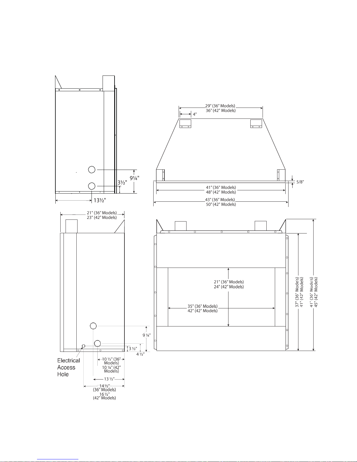
36" AND 42" MODELS
Note:
If
only one dimension
Left
Side
View
is
shown, the dimension
PRODUCT
is
the same
for
SPECIFICA
both 36" and 42"
Fireplace Top
TIONS
models.
View
Right
Side
View
Front
View
Figure
1 -
Fireplace Dimensions (36" and 42"
Models)
Page 7

6
Superiorfireplaces.US.com
127042-01_B
IMPORTANT:
set
will
Use dimensions shown
installation (see Built-In Fireplace Installation, page
Make sure fireplace
not work
properly.
is
level.
for
rough openings
If
fireplace
to
is
create
7).
not level,
the
INSTALLATION CLEARANCES
WARNING: Maintain the minimum clearances.
you can, provide greater clearances from floor,
and adjoining
Carefully
tion.
is installed.
Minimum
A.
B.
C. When fireplace
D.
follow
Fireplace hood
Wall and Ceiling Clearances (see Figure
Clearances from the side
tible material and wall should follow diagram
Example: The face of a
tible material and protrudes 3 1/2" from the wall. This
material must be 4"
Figure
2).
Clearances
should not be less than
material, other than wood flooring, fireplace should be installed
on
a metal
enclosure.
Clearances from bottom
Figure
wall.
these instructions. This
must be
used
of
the fireplace cabinet
mantel, bookshelf, etc. is made of
from
the side
from
the
top of
the fireplace opening
42".
is
installed
or
wood panel extending the
on
of
fireplace
Example
*Minimum 16" from Side Wall
2 -
Minimum Clearance for Combustible to
will
ensure safe
if
combustible mantel material
2)
of
the fireplace cabinet (see
carpeting
or
full
to
the floor
to
any
in
Figure
combustible
to
the
other combustible
width and depth
is 0".
*
Wall
INST
log
easiest
ceiling
installa
combus
2.
combus
ceiling
ALLA
TION
OUTDOOR ENCLOSURE REQUIREMENTS
Must conform
•
With walls
•
Within a partial enclosure which includes
to
on
one
of
the following conditions:
all
sides, but
with
no overhead cover;
an
overhead cover
no more than two side walls. These side walls may be
as in
If
breezeway
•
Within
a partial enclosure which includes an overhead cover
and three sidewalls, as long as 30%
periphery
or at right angles to each side; or
of
the enclosure
is
permanently
or
more
open.
CAUTION: Do not install the fireplace directly on
carpet or
-
vinyl.
WARNING: Fireplace hood must be used if a com
bustible mantel material is
-
Mantel Clearances for Built-In Installation
If
placing custom mantel above
the minimum allowable clearance between mantel shelf and
fireplace opening shown in Figure 3, page 6. These are the
allowable mantel clearances
ances wherever possible
materials placed on the
to
mantel.
installed.
built-in
for
a safe installation. Use larger
minimize
fireplace,
the
heating
NOTICE: Surface temperatures of adjacent walls
mantels become hot during operation.
of
mantels above the fireplace may become hot to
touch. If installed
properly,
these temperatures
the requirement of the national product standard.
low
all
minimum clearances shown in this
Facing material above firebox
must be of noncombustible
material. A 12" concrete board
projecting the width of the
fireplace is supplied.
12" Minimum
Framing
Material
Firebox
Wire-mesh
Screen
Figure
3 -
Minimum Mantel Clearances for Built-In
Mantel Shelf Note: Any portion
of the mantel shelf must NOT
extend beyond this profile.
12"
3
6
/
4"
1
1
/
2"
12"
16" 20"
Hood MUST be used if a
combustible mantel is installed.
Note:
All
vertical measurements
from top of
bottom
of
mantel
fireplace
shelf.
Noncombustible
Material May
Project Off this
Surface above
the Firebox Hood
hood
parallel,
of
the
horizontal
you must meet
top of
minimum
clear-
of
objects
and
Walls
and
the
meet
Fol-
manual.
are
opening
to
Installation
and
-
and
Page 8
127042-01_B
Superiorfireplaces.US.com
7
Rough Opening Dimensions for Built-in
Installation
Model
Front Width (Inside
to Inside)
Height
Depth
(Min.)
36"
44"
42 3/4"
21"
42"
51"
46 1/2"
23"
NOTICE: If your installation does not meet the
clearances shown, you must do one of the
• raise the
•
remove
mantel
to an acceptable height
the mantel
BUILT-IN FIREPLACE
1.
Frame
in
rough opening. The fireplace framing
structed
of
permanently fixed amount the perimeter
sions
in
Table 1 and rough opening layout
framing
installing
rough
2.
Install gas piping
so that
in
opening.
Supply, page
3.
Carefully
set
fireplace inside wall
4.
Carefully insert fireplace into rough
Table 1
37"
43"
Figure
INST
ALLA
TION
steel stud material. Steel studs are provided and
of
the unit. Use
in
fireplace
a corner, use dimensions
to
is flush with
finished
in
Figures
fireplace location (see Connecting
9).
fireplace
in front of
rough opening
opening.
opening.
FOR
MODELS
45°
Figure 4a
36"
Figure 4b
Height
Depth
(Minimum)
Widt
(Inside
74" TOP
VIEW
to
44"
h
Inside)
FOR 42"
MODELS
Figure 4c
45°
51"
86"
TOP VIEW
4 -
Rough Opening for Installing in
INSTALLATION
minimum
following:
must be con-
dimen-
Figure 4a.
wall
Wall
4b
with
Adjust
surface.
and
to
back
are
If
4c for
Gas
of
Continued
Steel Stud or
Steel Framing
Required.
Combustible
materials
not allowed
adjacent to
fireplace.
Figure
5 -
Installing
12'' minimum
noncombustible
wall board
or facing
material above
fireplace.
12'' minimum
noncombustible
wall board or facing
materials on sides.
Firebox
INSTALLING DRAIN PAN
The fireplace enclosure must allow
air ventilation.
catch pan
with
It is
provision
within fireplace enclosure (see Accessories, page
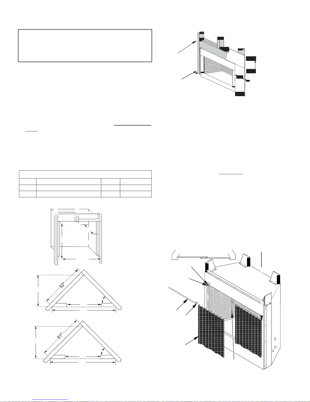
INSTALLING FIREPLACE SCREEN
1.
Insert each rod through all rings located at top
2.
Insert first rod into rear hole in left side of fireplace. Fasten rod
rear hole near center
provided (see Figure
3.
Insert other rod into front hole on right side of fireplace and
using remaining Phillips
Top View of Rod Layout
DP36/DP42
for
adequate drainage and
recommended that a sealed,
for
drainage
be
installed under fireplace
of
fireplace using #10 x 3/8" Phillips screw
6).
screw.
Identification
Label Location
corrosion resistant
24).
of
Rear Hole
Front
Hole
Rod
Ring
Screen
Screw
Figure
6 -
Installing Fireplace
Screen
screen.
fresh
to
fasten
Page 9
8
Superiorfireplaces.US.com
127042-01_B
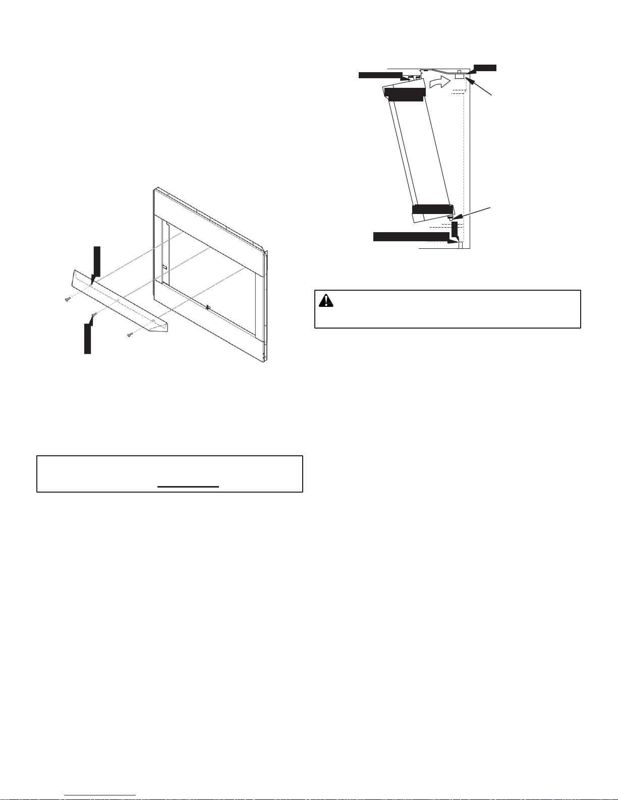
INSTALLING FIREPLACE HOOD
1.
Remove protective
2.
Align three notches located on back side of hood with front face
fireplace (see Figure 7). Notches should be at least
edge
of
fireplace
3.
Hold fireplace hood
three notches
4.
Insert three screws through notches in hood into holes in
film
opening.
in
.
HS36/HS42
from stainless
place. Using a #10
hood.
INSTALLATION
3 1/2" up
drill bit, drill
through
fireplace.
Notches
on Hood
Screws
INSTALLING BI-FOLD GLASS DOORS
IMPORTANT: Use only glass doors certified for use
with this fireplace (See Accessories,
Door
Installation
Pivot and spring clips have been installed and pretested at the
but
some readjustments may be needed due
shipping
Install doors using the following steps.
properly
door
1.
2. Repeat step
or handling.
or
adjustment.
With bi-fold door completely folded, insert bottom pivot pin
pivot plate
opening and swing door
pins slide into door track. Door is installed when top door pin snaps
into spring clip (see Figure
Figure 7 - Installing Hood
If
you find doors do not
do not appear level
or
pivot hole located near bottom corner
1 for
remaining
or
straight, proceed with section
to
the vertical position making sure
8).
door.
page
to
movement
24).
of
front face
factory,
during
of
from
close
on
into
top
Continued
Spring Clip
Fold
Door and
Slide Top
Pins into
Track
Pivot Plate
or Pivot
Hole
Insert Pin
into Spring
Clip
Insert Bottom
Pivot Pin into
Pivot Plate
or Hole and
Swing Door
into a Vertical
Position
Figure 8: Installing Bi-Fold Glass Door
WARNING: Fireplace must
doors fully
Door Adjustment
Remove doors and slightly loosen lower pivot plate
upper spring clips. Replace doors and fully close them. Use 1/8"
(any material)
carefully open doors enough so that you can access pivot and
clips with a
Please read the
ing your appliance
•
Glass
Figure 10, page
•
If
doors are not
off
burner. See Safety Device on page 15
to
reset the thermo
•
When
•
Always keep
or debris.
•
Do
not operate this
• Do not use abrasive liquids or cleaners for cleaning of glass and
door
clean doors when hot, allow the appliance to cool before
opened.
to
level doors. Once the proper setting
Phillips screwdriver. Tighten screws (see Figure 9, page
following care and operation guidelines before
or fireplace.
doors
should
be operated in the
9).
fully
open, the thermo disk
disk.
operating doors, do not slam shut or abuse them.
area
below
bottom edge of doors
appliance
trims.
Any household glass cleaner should suffice. Do
if
be
operated only
fully
open
for
glass doors are
with
(if
equipped)
is
achieved,
operat
position only
will automatically
instructions on
clear from
broken
obstacles
or damaged.
cleaning.
and
shims
spring
9).
-
(see
turn
how
not
Page 10

127042-01_B
Superiorfireplaces.US.com
9
INSTALLATION
Partially
Opened
Door
Spring
Clip
Continued
CONNECTING TO GAS
WARNING: A qualified service person must connect
heater to gas
WARNING: This appliance requires a 3/8" NPT
tional Pipe Thread) inlet connection to the control valve.
supply.
SUPPLY
Follow all local
codes.
(Na-
Figure 9: Door Adjustment
CAUTION: Never connect propane/LP unit directly to
the propane/LP
supply.
This unit requires an
external
regulator (not supplied). Install the external regulator
between the unit and the propane/LP
supply.
WARNING: Never connect natural gas
to private (non-utility) gas wells. This gas
monly known as wellhead
Figure 10: Bi-Fold Doors Fully Open
Installation Items Needed
Before installing heater, make sure you have the items listed below.
•
approved flexible gas
allowed by local codes)
•
external
•
piping
• sealant (resistant to
• equipment shutoff valve*
• test gauge connection*
• sediment trap
• tee joint
• pipe wrench
*
An equipment shutoff valve with 1/8" NPT tap
ternative to test gauge connection. Purchase the
shutoff valve from your
For propane/LP units, the installer must supply an external
The external regulator
reduce incoming gas pressure to between 11" and 14" of water.
do not reduce incoming gas pressure, control valve damage could
cur. Install external regulator with the vent pointing down as shown
Figure 11. Pointing the vent down protects it from freezing rain or
regulator
(check
local
hose and
(propane/LP
codes)
propane/LP
dealer.
will
reduce incoming gas pressure. You
Propane/LP
Supply Tank
Vent
Pointing
Down
gas.
fittings (supplied with appliance, if
models only)
gas)
External
Regulator
Figure 11 - External Regulator with Vent Pointing Down
fireplace
is
com
is
an acceptable
optional equipment
al-
regulator
must
If you
oc-
sleet.
-
.
in
Page 11

10
Superiorfireplaces.US.com
127042-01_B
REMOTE PROPANE/LP GAS SUPPLIES AND ENCLOSURES
If
appliance
from a remote supply tank, installation must be
local codes or,
Codes ANSI Z223.1/NFPA
Enclosures may
must be constructed
is to
be permanently connected
in
absence
of
local codes, with the National Fuel Gas
54.
be
used
to
conceal propane/LP supply tanks
to
meet the following minimum construction
to
a gas piping
in
accordance
system
requirements:
•
An enclosure must have either one open si
opposing vent openings,
requirements
•
Each opening
for
size and location (see Figure
must
top
and bottom, which meet
provide a minimum
cm2) of open area for each pound propane/LP contained in
supply
tank.
Example: A
have at least four, 10 square inches
(5 x
•
The
top
level.
•
The
bottom
(12.7 cm) above bottom
•
There
ground level
full
enclosure
13 cm)
square].
openings
must be 180°
openings
must be 180°
must be 2" (5 cm)
of enclosure.
for a 20
pound propane/LP tank
(65
opposing
opposing
floor.
minimum clearance from
de or at least four
minimum
12).
or 1/2 square inches (3,23
enclosed
cm2) openings
and be
and be
placed
the
[a
at
placed 5"
floor
CAUTION: Use only
new,
black iron or steel
pipe.
Internally-tinned copper tubing may be used in certain
INSTALLATION
areas. Check your local codes. Use pipe of 1/2"
eter or greater to allow proper gas volume to
If
pipe is too small, undue loss of volume will
Installation
plugged 1/8" NPT tap. Locate NPT tap within reach
hook up. NPT tap must be upstream from log set (see Figure
IMPORTANT:
tion.
the gas
Apply pipe joint sealant lightly to male NPT threads. This will
excess sealant
result
must
include
an
equipment shutoff valve, union
Install equipment shutoff valve
The equipment shutoff valve
to
the
appliance.
from
going
into
pipe. Excess sealant
in
clogged heater
valves.
is for
in
turning
an accessible
on or
for
test gauge
shutting
in
pipe
diam-
heater
occur.
13).
prevent
WARNING: Use pipe joint sealant that is resistant
to liquid petroleum (LP)
gas.
with
and
must
2" x 5"
valve
to
.
and
loca-
off
could
Continued
Minimum of 5" (12.7 cm)
From Floor To Top Of
Bottom Opening
Top
Openings
At Valve
Level
2 Openings
Top and
Bottom on
Each Side
Minimum
2
0.5 inch
(3.23 cm2)
of Free Air
Space For
Each Pound of
Fuel But No
Less Than
10 inches
(65 cm2) Total
2
Figure 12 - Propane/LP Tank Enclosure
Minimum 1/8"
(0.3 cm)
Permissible
Openings
Minimum of
2" (5 cm)
From Floor
Bottom To
Ground Level
We recommend that you install a
in Figure 13. Locate sediment trap where
Install
in
piping system between
sediment trap in supply line as
it
is within reach for
fuel
supply and appliance. Locate
sediment trap where trapped matter is not likely to freeze. A
trap traps moisture and contaminants. This keeps them from going
heater controls.
heater may not run
If
sediment trap
properly.
is
not installed
or is
installed
CAUTION: Avoid
control with wrench when connecting
and/or
* Purchase the optional shutoff valve from your dealer.
** Minimum inlet pressure for purpose of input adjustment.
fittings.
Approved Flexible
Gas Hose (If
allowed by local
codes)
damage to gas control. Hold gas
it
to gas piping
Equipment Shutoff
Valve with 1/8" NPT
Tap*
Natural
From Gas
Meter (5" W.C.**
to 10.5" W.C.
Pressure)
3" Min.
Pipe Cap Tee
Nipple Joint
Sediment Trap
Figure 13 - Gas Connection
Propane/LP
From External
Regulator (11"
W.C.** to 14"
W.C. Pressure)
cleaning.
sediment
shown
into
wrong,
Page 12

127042-01_B
Superiorfireplaces.US.com
11
CHECKING GAS CONNECTIONS
INSTALLATION
WARNING: Test all gas piping and connections for
leaks after installing or servicing. Correct
at
once.
all
WARNING: Never use an open flame to check for
a
leak. Apply a noncorrosive leak detection fluid to
all
joints. Bubbles forming show a leak. Correct
leaks at
installed between propane/LP supply and
See guidelines under Connecting to Gas Supply,
PRESSURE TESTING GAS SUPPLY
Test Pressures In Excess Of 1/2 PSIG
The appliance and its appliance main gas valve must be
from the gas supply piping system during any pressure testing of
system at test pressures
1.
Disconnect appliance with
valve) and equipment shutoff valve from gas supply piping
Pressures
2.
Cap off open end of gas pipe where equipment shutoff valve
connected.
3.
Pressurize supply piping system
supply tank valve
located on or near gas meter for natural gas
air.
4.
Check all joints of gas
leak detection fluid
5.
Correct all leaks at
6.
Reconnect heater and equipment shutoff valve
Check reconnected fittings
Test Pressures Equal To or Less Than 1/2 PSIG
The appliance must be isolated
by closing its equipment shutoff valve during any pressure testing
the gas supply piping system at test pressures
1/2 psig (3.5
1.
Close equipment shutoff valve (see Figure
2.
Pressurize supply piping system
supply tank valve
located on or near gas meter for natural gas
air.
3.
Check
natural gas
propane/LP (see Figure 15 or 16). Apply noncorrosive leak detec
tion fluid
4.
Correct all leaks at
once.
CAUTION:
in
excess
kPa).
all
joints
or
to
all joints. Bubbles forming show a
Make sure external regulator has been
appliance.
page
PIPING SYSTEM
(3.5 kPa)
disconnected
in excess of
of
1/2 psig
for
propane/LP gas
supply piping system. Apply noncorrosive
to
all joints. Bubbles forming show a
once.
for
propane/LP gas
from
gas meter
propane/LP supply
once.
1/2 psig (3.5
its
appliance main gas valve
will
damage control
by
either opening propane/LP
or
for leaks.
from
the gas supply piping system
by
either opening propane/LP
or
to
equipment shutoff valve
to
equipment shutoff valve
kPa).
opening main gas valve
or using compressed
(3.5 kPa)
equal to or less
14).
opening main gas valve
or using compressed
leak.
to
valve.
gas
leaks
all
9.
that
(control
system.
was
leak.
supply.
of
than
for
for
Continued
Equipment
Shutoff
Valve
Pressure Testing Appliance Gas Connections
1.
Open equipment shutoff valve (see Figure
2.
Open main gas valve located on or near gas meter for natural
or
open propane/LP supply tank
3.
Make sure control knob
4.
Check all joints from equipment shutoff valve to gas control
Figure
joints. Bubbles forming show a
5.
Correct all leaks at
6.
Light appliance (see Operation, page 12) Check
joints
7.
Turn
Propane/LP
Supply Tank
Figure 15 - Checking Gas Joints (Propane/LP Gas
Figure 14 - Equipment Shutoff Valve
of
appliance
15 or 16).
for leaks.
off appliance.
Apply noncorrosive leak detection
leak.
once.
Equipment
Shutoff Valve
Equipment
Gas Meter
-
Figure 16 - Checking Gas Joints (Natural Gas
Shutoff Valve
Control Valve
Location
Open
Closed
14).
valve.
is in
the OFF
Control Valve
Location
gas
position.
(see
fluid to all
all other internal
Only)
Only)
Page 13

12
Superiorfireplaces.US.com
127042-01_B
INSTALLATION
PLACEMENT OF LOOSE EMBERS
Continued
CAUTION: Do not
pilot
assembly.
Two bags
stallation use the embers that are approximately 1" square
needed, larger embers can be broken
concealing the burner pan, directing flames through the ember
quiet operation of the unit and gives a natural random flame pattern.
Place embers as
1.
2.
3.
of
loose embers are provided
follows:
Place embers around center ember bed
Place individual embers on their edge (not flat) along the top
burner pan. This aids in directing flames from the burner
ember
bed.
Note:
Too many embers
can suppress the
When unit is
bed glowing red-orange in color (see Burner Flame Pattern,
13).
If
embers.
ing loose
lit,
this is not happening, either add, remove or reposition
IMPORTANT:
embers.
Figure 17 - Placement of Embers
place any loose embers around
with this unit.
to
size. These embers aid
or
ember
or
embers placed flat along burner
flames.
check flames for random appearance and
Turn unit off and let cool before
For
in
pod.
reposition
this in-
size.
through
ember
page
loose
If
in
bed,
of
pan
OPERATION
FOR YOUR SAFETY READ
WARNING:
BEFORE
If
you do not follow these instructions
exactly, a fire or explosion may
damage, personal injury or loss of
A.
This appliance has a pilot which must be lighted with a piezo
ignitor.
exactly.
B.
BEFORE LIGHTING smell all
Be sure to smell next to the floor because some gas
than air and will settle on the
WHAT TO DO IF YOU SMELL GAS
•
•
Do
•
•
-
C.
Use only your hand to push in or turn gas control knob. Never
use tools.
try to repair
repair may result in
D.
Do not use this appliance
Immediately call a qualified service technician to inspect
appliance and to replace any part of the control system and any
gas control which has been under
When lightning
Do not try
building.
Immediately
Follow the gas supplier’s instructions.
If you cannot reach your
to
light any
not touch any electric switch; do not use any phone in your
call
If
the knob
it,
call a qualified technician. Force or attempted
the
around the appliance area for
appliance.
your gas supplier from
gas
will
not push
a fire.
if
LIGHTING
result
caus
ing proper
life.
pilot, follow these
floor.
a
neighbor’s
supplier,
any part has been under
call the
in
or turn by hand, do not
water.
fire
LIGHTING
INSTRUCTIONS
1.
STOP! Read the safety information,
2.
Make sure switch
3.
Be sure gas line shut-off valve
4.
Press in and turn control knob
tion (see Figure 18, page
Note:
Knob cannot be turned from PILOT
pushed
5.
Wait five
STOP! Follow "B"
don't smell gas, go on the next
6.
Press
PILOT position. Press
Figure 18, page
7.
With control knob pressed
This
pilot
Note:
or
8.
Keep control knob pressed
After 30 seconds, release
•
in
slightly. DO NOT FORCE.
(5)
in
and
will
light pilot.
lights.
If
pilot does not stay
gas supplier
If
control knob does not pop out when released, turn off
supply and contact a qualified service person
for repairs.
is in
minutes
in
the safety information
turn
control knob
13).
If
for repairs.
the OFF
to
in
needed, keep pressing ignitor button
position.
is
clockwise
13).
clear out any gas.
control knob
in,
lit,
contact a qualified service person
in for
control knob.
above.
OPEN.
to the OFF
to
OFF unless knob
If
you then smell
in
column
step.
counterclockwise to the
for
five
(5)
seconds
press and release
30 seconds after
ignitor button.
lighting pilot.
or
ty
instructions
gas.
is heavier
phone.
department.
water.
the
posi-
gas,
1. If you
(see
until
gas
gas
supplier
is
Page 14

127042-01_B
Superiorfireplaces.US.com
13
OPERATION
Note:
If
pilot goes out, repeat steps 4 through
9.
Slightly push
to
the ON
10. Wait one minute and move switch
in
and
position.
turn
Continued
control knob
to the
8.
counterclockwise
ON position
to light
burner.
Note:
AUTO
is only functional when using optional remote
accessory.
11. Set flame adjustment knob
to
any level between HI and
LO.
Control
Knob
Piezo
Ignitor
Flame Adjustment Knob
TO TURN OFF GAS
Figure 18 - Setting Control Knobs
TO APPLIANCE
1.
Push switch into
OFF
position. The pilot will remain
service.
2.
Access
3.
Press gas control knob slightly and turn clockwise to
control knobs.
force.
4.
Close equipment shutoff valve (see Figure 14, page
HAND-HELD
REMOTE
OPERA
TION
lit
for
OFF. Do
10).
NOTICE: You must light
hand-held remote control unit. See Lighting Instruc
tions,
After
control knob to
anywhere between
the
Note:
switch was last turned
with the hand-held remote control
IMPORTANT:
position when the pilot
page
12.
lighting,
let pilot
ON position. Adjust flame adjustment
HI and LO. Slide the
REMOTE position
The burner may light
Do not leave the selector switch in the REMOTE or ON
off.
is
Piezo
Igniter
Control Knob
the
pilot before using
flame
burn for
on
Remote Receiver
if
hand-held remote was on when selecto
about
one
minute. Turn
selector
(see
switch to
Figure
You can now turn the burner on and
unit.
not
lit.
This
will
drain the battery.
REMOTE
OFF
ON
Flame Adjustment
Knob
Figure 19 - Settings for Remote Operation
Selector Switch in
REMOTE Position
control
normal
not
the
-
knob
19).
off
INSPECTING BURNERS
Check pilot flame pattern and burner flame patterns
PILOT
ASSEMBLY
The
pilot
assembly
is
factory preset
for the
often.
proper flame
Alterations may have occurred during shipping and handling. Call a
qualified service person
The height
flame as shown
of
about 1/8" above the pilot flame. The flame from the pilot
of the
in
must extend beyond both the thermocouple and
If
you pilot assembly does not meet these requirements:
• turn
fireplace off
• see
Troubleshooting, page
to
readjust the pilot
thermopile
must be
if necessary.
3/8"
to
1/2" above
the pilot
Figure 20. The thermocouple must be at a
thermopile.
(see
To Turn Off Gas
to
Appliance
)
16
BURNER FLAME PA
Figure
21 shows correct burner flame pattern.
NOTICE: Do not
TTERN
mistake orange flames with yellow
tipping. Dirt or other fine particles are burned by
pliance, causing brief patches of orange
If
burner flame pattern
• turn
appliance off
• see
Troubleshooting, page
is
incorrect, as shown
(see
To Turn Off Gas
16
to
Appliance
in
flame.
Figure
22.
)
Thermopile
r
Figure 22 - Incorrect Burner Flame
3/8" to 1/2"
Piezo
Ignitor
Figure 20 - Pilot Assembly
Yellow Flames with
Figure 21 - Correct Burner
Orange Streaks
Pilot Burner
1/8"
Thermocouple
Flame Pattern
Dark Orange
Flames
Pattern
height.
height
burner
ap-
Page 15

14
Superiorfireplaces.US.com
127042-01_B
ADJ.
LEAR
N
O
FF
REMOT
E
ON
INSPECTING BURNERS
Continued
OPTIONAL HAND-HELD REMOTE CONTROL ACCESSORIES - MRC
NOTICE: Use only alkaline batteries (included with
MRC).
Installing
1.
2.
Receiver
Disconnect jumper wires from the control valve (see Figure
Locate the battery cover on the back
of
the receiver (see Figure
24).
3.
Install 4-AA batteries (included) into receiver before installing
fireplace.
4.
Connect wires from remote receiver to control valve. See
tions provided with remote control
kit for
further
instruc-
information.
Figure 23 - Disconnecting Jumper Wires From Control V
Requires 4-AA
alkaline
batteries
1.5V
alve
Learning
button
Slide
Switch
ON
REMOTE
OFF
Frequency
adjusting
access
hole
Remote
Receiver
Figure 24 - Attaching Batteries to
Receiver
CLEANING AND
MAINTENANCE
WARNING: Turn off the appliance and allow to cool
before
cleaning.
CAUTION: You must keep control areas, burners
23).
and circulating
Inspect these areas of fireplace before each use. Have
fireplace inspected yearly by a qualified service person.
air
passageways of fireplace
Fireplace may need more frequent cleaning due to
into
excessive lint from carpeting, bedding material,
Only limited cleaning
pliance. Dust the
cleaning fluids
If,
after a period
and behavior
or
holes may require some cleaning.
that you contact your nearest authorized service technician
the appliance
•
Keep
•
Periodically inspect
serviced.
area around log set clean and clear of debris.
blocking the air inlet and flame
HIGH ALTITUDE
When the fireplace
may need to decrease the input rating by changing the existing
orifice
to
a smaller size. Reduce input 4%
2000 feet which they are installed. Check with your local gas
for
proper orifice size
High Temperature
The high temperature
hand corner of the firebox. This feature will prevent the fireplace
operating at abnormally high temperatures. The burner will
cally
turn
off without interrupting
lock out and must be reset manually. To reset the
1.
Turn
off
the burner by turning the gas control knob clockwise
the
off position.
2.
Remove
3.
Carefully pull
4.
Mount
limit
limit
moved.
5.
Re-light the burner following instructions on page
will
be required under normal use
front
grate and
to
clean logs
of
use, the flames start
the burner fails
the
air mixer
top of
receiver/valve. Do
or
any other part
to
exhibit unusual shapes
to
ignite smoothly, then the
If this
happens, we recommend
and burner tube
of
holes.
INST
ALLA
TION
is
installed at an elevation above 2000 feet,
for
every 1000 feet above
identification.
SAFETY DEVICE
Limit Switch
limit
switch
is
the
located inside the upper
pilot flame;
switch plate by removing two screws.
limit
plate out and press the reset
switch plate back using
two
screws previously
WARNING: Only a qualified service person should
service the
fireplace.
of this ap-
the
appliance.
for foreign
automati-
the
limit switch
limit switch:
button.
12.
clean.
etc.
not use
burner
to get
matter
you
burner
company
right
from
will
to
re-
Page 16

127042-01_B
Superiorfireplaces.US.com
15
SPECIFICA
VRE3036ZMN
•
Rating (Variable):
• Gas
Type:
Natural
•
Ignition:
•
Manifold
•
Inlet
Piezo
Pressure:
Gas Pressure (inches of water):
28,000/41,000 Btu/Hr
3.5"
Max. 10.5" W.C., Min. 5.0" W
•
Air
Shutter: 3/16 OPEN
W.C.
.C.*
VRE3036ZMP
•
Rating (Variable):
• Gas
Type:
Propane/LP
•
Ignition:
•
Manifold
•
Inlet
Piezo
Pressure:
Gas Pressure (inches of water):
Max. 14" W.C., Min. 11"
•
Air
Shutter:
FULLY
32,000/41,000 Btu/Hr
10"
W.C.
W.C.*
OPEN
WIRING DIAGRAM
WARNING: Fireplace must be operated only with doors fully
TIONS
VRE3042ZMN
•
Rating (Variable):
• Gas
Type:
•
Ignition:
•
Manifold
•
Inlet
Piezo
Pressure:
Gas Pressure (inches of water):
32,000/47,000 Btu/Hr
Natural
3.5"
Max. 10.5" W.C., Min. 5.0" W
•
Air
Shutter: 3/16 OPEN
VRE3042ZMP
•
Rating (Variable):
• Gas
Type:
•
Ignition:
•
Manifold
•
Inlet
Piezo
Pressure:
Gas Pressure (inches of water):
35,000/45,000 Btu/Hr
Propane/LP
10"
Max. 14" W.C., Min. 11"
•
Air
Shutter:
*For purpose
FULLY
of
input
OPEN
adjustment
open.
W.C.
W.C.
W.C.*
.C.*
Page 17

16
Superiorfireplaces.US.com
127042-01_B
TROUBLESHOOTING
WARNING: Turn off heater and
and repair
heater.
let
cool before servicing. Only a qualified service person should service
CAUTION: Never use a wire, needle or similar object to clean pilot. This can damage pilot
Note:
All troubleshooting items are listed
OBSERVED PROBLEM
When ignitor button is pressed, there is
spark at
When
spark at pilot but no
pilot
ignitor button is
ignition
pressed, there
Burner does not light after pilot
is lit
no
is
in
order
of operation.
POSSIBLE CAUSE
1. Ignitor electrode not connected to
cable
2. Ignitor cable pinched
3. Piezo ignitor nut
4. Broken ignitor
5. Bad piezo
6. Ignitor electrode
7. Ignitor electrode positioned
1. Gas supply turned
shutoff valve
2. Gas control knob not
3. Gas control knob not pressed
PILOT
4. Air
in
gas lines when
5. Depleted gas supply (propane/LP
only)
6. Pilot
is clogged
7. Gas regulator setting
1. Burner orifice
2. Inlet gas pressure
3. Thermopile leads disconnected
properly
4. Thermopile
cable
ignitor
closed
position
clogged
connected
is defective
or wet
is loose
broken
wrong
off or equipment
in
PILOT
in
installed
is
not
correct
is
too
low
ignitor
position
while
in
models
or im-
REMEDY
1. Reconnect ignitor
2. Free ignitor cable
or
tubing. Keep ignitor cable
3. Tighten nut holding piezo ignitor. Nut
located behind the mounting
4. Replace ignitor
5. Replace piezo
6. Replace pilot
7. Tighten electrode. Replace
1. Turn
shutoff
2. Turn gas control knob
3. Press in gas control knob while in
position
4. Continue holding
Repeat
removed
5. Contact local propane/LP gas
6. Clean
nance, page 14) or replace pilot assembly
7. Replace gas
1. Clean burner (see Cleaning and
nance, page 14) or replace burner
2. Contact local propane/LP
company
3. Reconnect leads to TP & TPTH
on control
4. Replace
cable
ignitor
assembly
on
gas supply
valve
igniting
pilot
(see Cleaning and
regulator
valve
thermopile
unit.
cable
if
pinched by any
dry
if necessary
or
open equipment
to
PILOT
down control
operation
or
metal
is
bracket
position
PILOT
knob.
until air is
company
Mainte
Mainte
orifice
natural gas
terminals
-
-
Page 18

127042-01_B
Superiorfireplaces.US.com
17
OBSERVED PROBLEM
Pilot lights but flame goes out when
knob
is released
Delayed ignition
Burner backfiring during
Slight smoke or odor during initial operation
burner
combustion
control
Heater produces a whistling noise when
burner
is lit
Fireplace produces a
just after burners are
Remote does not
clicking/ticking noise
lit or
shut
off
function
TROUBLESHOOTING
POSSIBLE CAUSE
1. Gas control knob not fully pressed
2. Gas control knob
enough
3. Equipment shutoff valve not fully
4. Pilot flame
which allows thermocouple to
pilot flame to go out. This problem could
caused by one or both of the
A) Low gas pressure
not
not
touching thermocouple,
B) Dirty
or
partially clogged
5. Thermocouple connection loose at
trol valve
6. Thermocouple
7. Control valve
damaged
damaged
1. Manifold pressure
is
too
2. Burner porting
or
orifice
1. Burner orifice
2. Damaged
3. Gas regulator
1. Residues
and logs
1. Turning gas control knob
when burner
2. Air
in
gas
is
clogged
burner
defective
from manufacturing processes
curing
is cold
line
3. Dirty
or
partially clogged burner
1. Metal expanding while heating
tracting while
1. Battery
is low
cooling
is
not installed
Continued
pressed
low
clogged
or damaged
or
in long
open
cool, causing
following:
pilot
to HI
position
orifice
or con-
battery power
in
con-
REMEDY
1. Press
2. After pilot lights, keep gas control
3. Fully open equipment shutoff
4.
be
5. Hand tighten until snug, then tighten
6. Replace pilot
7. Replace control
in
gas control knob
pressed
A)
gas
B) Clean pilot (see Cleaning and
nance, page 14) or replace pilot assembly
turn
in
30
seconds
Contact local natural
company
more
assembly
valve
1. Contact local propane/LP
company
2. Clean burner (see Cleaning and
nance, page 14) or replace burner
1. Clean burner (see Cleaning and
nance, page 14) or replace burner
2. Replace damaged
3. Replace gas
burner
control
1. Problem
operation
will stop
after a few hours
1. Turn gas control knob to LO position
let warm up
2. Operate burner until air is removed
line. Have gas line checked by local
pane/LP
3. Clean burner (see Cleaning and
nance, page 14) or replace burner
for a minute
or
natural gas
1.
This is
contact qualified service
normal.
If
noise
1. Replace batteries
held remote control (see page
in
fully
knob
valve
or propane/LP
Mainte
-
1/4
or
natural gas
Mainte
orifice
Mainte
orifice
of
and
from
pro-
company
Mainte
orifice
is
excessive,
person
receiver and hand-
14)
-
-
-
Page 19

18
Superiorfireplaces.US.com
127042-01_B
WARNING:
•
Shut off
•
Do not try
•
Do not touch any
•
Leave the building
•
Immediately
•
If you cannot reach your
OBSERVED PROBLEM
Fireplace produces unwanted
gas
to
If
you smell gas
supply.
light any
appliance.
electrical
immediately.
call
your
odors
switch;
gas
supplier from a neighbor’s
gas
Fireplace shuts
off in use
Gas odor even when control knob is in OFF
position
Gas odor during
combustion
Dark residue on logs
or
inside
of
fireplace
TROUBLESHOOTING
do
not
use
supplier, call the
POSSIBLE CAUSE
1. Gas leak. See Warning statement above
1. High
or
2. Low line
gusting
3. Pilot
is
partially
4. Inner vent pipe leaking exhaust gasses
into
system
5. Glass too loose and air tight gasket leaks
in
corners after
6. Bad thermopile
7. Improper vent cap
8. Abnormal temperature
doors not being fully
1. Gas
leak.
2. Control valve
1. Gas
leak.
1. Air holes at burner inlet
2. Burner flame holes
3. Improper venting
4. Excessive amounts
material
Continued
any phone
fire
department.
winds
pressure
clogged
usage
or thermocouple
See Warning statement above
defective
See Warning statement above
in
your
phone.
installation
in
firebox due
open
blocked
blocked
or
excessive
of
embers and
building.
Follow
blockage
pan
the gas
to
supplier’s
REMEDY
1. Locate and correct all leaks (see
Gas Connections, page
instructions.
11)
Checking
1. Fireplace has been tested
mph winds. However, extreme
may occur. See Lighting Instructions
page
12
2. Contact local propane/LP
company
3. Clean
4. Locate and correct all leaks (see
5. Tighten
pilot
(see Cleaning and
nance, page
Gas Connections, page
14)
glass
for up to 40
conditions
or
natural gas
Checking
11)
6. Replace faulty
7. Check for proper installation and
from debris
8. See Safety Device, page
component
or blockage
14
1. Locate and correct all leaks (see
Gas Connections, page
2. Replace control
valve
1. Locate and correct all leaks (see
Gas Connections, page
1. Clean out air holes at burner inlets.
odically repeat as
2. Remove blockage
3. Have the vent system inspected,
the termination cap. Remove any
tions
or obstruction
4. Clear excess embers until a
of
1/2" remains under the
needed
or
replace
11)
11)
minimum
grate
Checking
Checking
burner
including
on
Mainte
freedom
Peri-
restric-
gap
-
Page 20

127042-01_B
Superiorfireplaces.US.com
19
When Gas Pressure
•
pilot will
• burner
•
fireplace will
•
for propane/LP unit, propane/LP gas supply may
not stay lit
will
You may feel your gas pressure
gas
supplier.
Is
have
delayed
not produce
Too
Low
ignition
specified
is
too low.
TECHNICAL SERVICE
SERVICE HINTS
heat
be
low
If
so, contact your
You may have further questions about installation, operation,
troubleshooting. Please contact your IHP dealer
or
concerns. When contacting your dealer please have
and serial numbers of your fireplace ready. You can also
site at Superiorfireplaces.US.com.
for
any questions
your model
visit our web
local
or
REPLACEMENT PARTS
See Pages 20
parts supplied from the
Normally,
or
dealer. Parts
When ordering repair parts, always give the following
1. The model number
2. The serial number
3. The part
4. The description
5. The quantity
6. The installation date
If
you encounter any problems or have any questions concerning
installation or application of this fireplace, please contact your dealer.
IHP
1508 Elm Hill Pike, Suite
Nashville, TN
Visit us at
to
23
for
a complete replacement parts
manufacturer.
all
parts should be ordered through your IHP
will
be shipped at prevailing prices at time
of
the
fireplace.
of
the
fireplace.
number.
of
the
part.
required.
of
the
fireplace.
108
37210
Superiorfireplaces.US.com
list.
Use
distributor
of order.
information:
only
the
Page 21

20
Superiorfireplaces.US.com
127042-01_B
CATALOG
NO.
MODEL
F0519
VRE3036ZMN
F0520
VRE3036ZMP
F0521
VRE3036ZMN
F0522
VRE3036ZMP
F0523
VRE3036ZMN
F0524
VRE3036ZMP
F0525
VRE3036ZMN
F0526
VRE3036ZMP
F0527
VRE3042ZMN
F0528
VRE3042ZMP
F0529
VRE3042ZMN
F0530
VRE3042ZMP
F0531
VRE3042ZMN
F0532
VRE3042ZMP
F0533
VRE3042ZMN
F0534
VRE3042ZMP
PARTS
34
22
19
34
22
25
26
27
27
29
24
21
20
17
16 18
23
14 30
5
32
12
11
10
33
33
3
4
2
7
6
1
29
15
13
31
9
8
Page 22

127042-01_B
Superiorfireplaces.US.com
21
This
J4102
Wire
Harness
• • • •
1
J8041
Flex Gas
Line
• • • •
1 J4863
Ember Flakes
Kit • • • • 2
list
page 19
contains replaceable parts used
of
this
manual.
PARTS
in
your firebox. When ordering parts, follow the instructions listed under Replacement Parts
WARNING: Contact an IHP dealer to obtain any of these parts. Never use substitute materials not approved
by IHP.
KEY NO. CATALOG
1
2
3
4
5
6
7
8 J5008 1 1/4" Elbow Venturi
9 J4794
10 J5197
11 J4973
12 J4733
13 J6752
14 J6830
15 J5435
16 J3546
17 J4046
18 J6833
19
20 J4717
21 J5450
22 J6918
23 J6895
24 J6436
25
26 J5329
27 J6934
28 J6900
29 J8012
30 J6238
31 J6431
32 J6430
33 RP125355-01
34 RP125353-01
Use of non-approved parts can result in poor performance and safety
NO.
See Pages 22
See Pages 22
See Pages 22
See Pages 22
See Pages 22
See Pages 22
See Pages 22
J5007 1 1/4" Elbow Venturi
J4974
J4972
J4971
J6753
J6831
J5436
J5432
J8000
**
**
J5451
**
**
J8013
RP125354-02
RP125355-02
DESCRIPTION
& 23
Refractory, Bottom Rear
& 23
Refractory, Bottom Right
& 23
Refractory, Bottom
& 23
Refractory, Bottom Center
& 23
Refractory,
& 23
Refractory,
& 23
Refractory,
Venturi
Air
Brass Orifice NG
Brass Orifice
Brass Orifice NG
Brass Orifice
3/8" Compression
Assembly, Pilot NT.
Assembly, Pilot LP.
Gas Valve
Gas Valve
Log Set and NG
Log Set and LP
Log Set and NG
Log Set and LP
Piezo
Valve
3/8 x 3/8 Brass
Fireplace Top
Fireplace Top
Dormont T6-36 3.8 x 18" Flextube
Log Set
Log Set
Top
Firebrick
High Limit Switch
Fireplace
Fireplace
Handle
Gas Conduit
Cover Outside Air
Screen Assembly
Screen Assembly
Fitting, 1/2" FLR x 3/8"
Pilot
Frame, Top
Frame, Top
Frame,
Frame,
Top
Left • • • •
Right • • • •
Rear • • • •
Gasket • • • •
Shutter • • • •
LP • 1
LP • 1
(Natural) • •
(Propane/LP) • • 1
Ignitor • • • •
Bracket • • • •
• •
• • 1
Retainer • •
Retainer • • 2
Spacer • • • •
Retainer • • • •
Surround • •
Surround • • 1
Bracket • • • •
Cover • • • •
Sheild • •
• •
• • 1
Sides • •
Sides • • 2
Spacer • • • •
VRE3036ZMN VRE3036ZMP VRE3042ZMN VRE3042ZMP
• • • •
• • • •
Left • • • •
• • • •
• •
• • 1
•
• 1
Nut/Sleeve • • • •
(Alpine) • •
(Alpine) • • 1
Chassis •
Chassis • 1
Chassis • 1
Chassis • 1
Adapter • • • •
• • • •
Assembly • • • •
Plate • • • •
Kit • •
Kit • • 1
MPT • • • •
PARTS AVAILABLE — NOT SHOWN
hazards.
on
QTY.
1
1
1
1
1
1
1
1
1
1
1
1
1
1
1
1
1
1
1
1
2
2
2
1
1
4
4
1
1
1
1
1
2
2
J6533
On/Off
Remote • 1
Page 23

22
Superiorfireplaces.US.com
127042-01_B
CATALOG
NO.
MODEL
F0527
VRE3042ZMN
F0528
VRE3042ZMP
F0529
VRE3042ZMN
F0530
VRE3042ZMP
F0531
VRE3042ZMN
F0532
VRE3042ZMP
F0533
VRE3042ZMN
F0534
VRE3042ZMP
PARTS
CATALOG
NO.
MODEL
F0519
VRE3036ZMN
F0520
VRE3036ZMP
F0521
VRE3036ZMN
F0522
VRE3036ZMP
F0523
VRE3036ZMN
F0524
VRE3036ZMP
F0525
VRE3036ZMN
F0526
VRE3036ZMP
WARNING: Contact an IHP dealer to obtain any of these parts. Never use substitute materials not approved
by IHP.
Use of non-approved parts can result in poor performance and safety
hazards.
5
7
6
3
4
1
2
Page 24

127042-01_B
Superiorfireplaces.US.com
23
This
1
J5986
J5980
REFRACTORY, BTM REAR
36" WHITE
REFRACTORY, BTM REAR
42" WHITE
• •
•
•
1
1
2
J5988
J5982
REFRACTORY, BTM FRONT RT
.36"WHITE
REFRACTORY, BTM FRONT RT
.42"WHITE
• •
•
•
1
1
3
J5990
J5984
REFRACTORY, BTM FRONT LT
.36"WHITE
REFRACTORY, BTM FRONT LT
.42"WHITE
• •
•
•
1
1
4
J5427
REFRACTORY, BTM-CTR ASM, WHITE
36/42
• • • •
1
5
J6368
J8296
J6380
J6389
REFRACTORY, LT,STD,WHITE
C36
REFRACTORY, LT, WHITE HERR
C36
REFRACTORY, LEFT, WHITE
42
REFRACTORY, LEFT, WHITE HERR
42
•
•
•
•
1
1
1
1
6
J6369
J6376
J6382
J8297
REFRACTORY, RT,STD,WHITE
C36
REFRACTORY, RT, WHITE HERR
C36
REFRACTORY, RIGHT, WHITE
42
REFRACTORY, RIGHT, WHITE HERR
42
•
•
•
•
1
1
1
1
7
J6371
J6377
J6384
J8298
REFRACTORY, REAR,STD,WHITE
C36
REFRACTORY, REAR, WHITE HERR
C36
REFRACTORY, REAR, WHITE
42
REFRACTORY, REAR WHITE HERR
42
•
•
•
•
1
1
1
1
1
J5987
J5981
REFRACTORY,BOTTOM REAR 36" RED
REFRACTORY,BOTTOM REAR 42" RED
• •
•
•
1
1
2
J5989
J5983
REFRACTORY,BTM FRONT RT. 36" RED
REFRACTORY,BTM FRONT RT. 42" RED
• •
•
•
1
1
3
J5991
J5985
REFRACTORY,BTM FRONT LT. 36" RED
REFRACTORY,BTM FRONT LT. 42" RED
• •
•
•
1
1
4
J5428
REFRACTORY, BTN-CTR ASM, RED
• • • •
1
5
J7514
J7617
J6381
J6390
REFRACTORY, LT,STD,RED
36"
REFRACTORY, LT, RED
36" HERR
REFRACTORY, LEFT, RED
42"
REFRACTORY, LEFT RED
42" HERR
•
•
•
•
1
1
1
1
6
J6370
J7619
J6383
J6391
REFRACTORY, RT,STD,RED
36"
REFRACTORY, RIGHT, RED
36" HERR
REFRACTORY, RIGHT, RED
42"
REFRACTORY, RIGHT, RED
42" HERR
•
•
•
•
1
1
1
1
7
J7515
J7630
J6385
J6392
REFRACTORY,REAR,STD,RED
36"
REFRACTORY, REAR RED
36" HERR
REFRACTORY, REAR, RED
42"
REFRACTORY, REAR RED
42" HERR
•
•
•
•
1
1
1
1
page 19
list
contains replaceable parts used
of
this manual
KEY
NO.
.
CATALOG
NO.
DESCRIPTION
PARTS
in
your firebox. When ordering parts, follow the instructions listed under Replacement Parts
VRE3036
ST
ACKED
F0519
F0520
VRE3036
H.BONE
F0521
F0522
VRE3042
ST
ACKED
F0527
F0528
VRE3042
H.BONE
F0529
F0530
QTY
.
on
KEY
NO.
CATAL OG
NO.
DESCRIPTION
VRE3036
ST
ACKED
F0523
F0524
VRE3036
H.BONE
F0525
F0525
VRE3042
ST
ACKED
F0531
F0532
VRE3042
H.BONE
F0533
F0534
QTY.
Page 25

24
Superiorfireplaces.US.com
127042-01_B
Purchase these accessories from your local dealer.
for information.
CAT
NO.
F1077 MRC
F1052 HS36
F1053 HS42
F1089 DP36
F1090 DP42
F0987 BDO36
F0988 BDO36B
MODEL
DESCRIPTION
RECEIVER AND HAND-HELD REMOTE CONTROL
Standard On/Off Remote Control
FIREPLACE HOOD
36" Stainless Steel Hood w/4"
42" Stainless Steel Hood w/4"
DRAIN PAN
36" Drain Pan
Extension
42" Drain Pan
Extension
w/
w/
BI-FOLD GLASS DOORS
36" Outdoor Bi-Fold Glass Door - Black
36" Outdoor Bi-Fold Glass Door - Brushed Brass
ACCESSORIES
If
they can not supply these accessories, contact IHP at Superiorfireplaces.US.co
Kit
(Not
Brow
Brow
1" Stainless Decorative Face
1" Stainless Decorative Face
finish
finish
(Not
shown)
shown)
m
F0989 BDO36P
F0990
F0991 BDO42B
F0992 BDO42P
F1034
F1035
BDO42
OC36
OC42
36" Outdoor Bi-Fold Glass Door - Platinum
42" Outdoor Bi-Fold Glass Door - Black
42" Outdoor Bi-Fold Glass Door - Brushed Brass
42" Outdoor Bi-Fold Glass Door - Platinum
METAL OUTDOOR
Door for closing unit when not in
36" Outdoor Fireplace Panel
42" Outdoor Fireplace Panel
COVER
use
Cover
Cover
finish
finish
finish
finish
Page 26

127042-01_B
Superiorfireplaces.US.com
25
NOTES
Page 27

26
Superiorfireplaces.US.com
127042-01_B
NOTES
Page 28

127042-01_B Superiorfireplaces.US.com 27
Printed
in
U.S.A.
P/N 900223-00,
Superior
THE WARRANTY
Innovative Hearth Products ("IHP")
and workmanship
thermal
breakage
Warranty period and while the Product remains at the site
is not
commercially practical, IHP
ing labor
to this 20
COVERAGE COMMENCEMENT DATE
Warranty coverage begins
months after the
the
date
EXCLUSIONS AND
This 20
Year
instructions
This
warranty
provided. The Product
this 20
Year
Burner – Repair
Gas components – Repair
Gaskets – Repair
Logs – Replacement
Optional blowers & remote controls – Repair
Optional glass doors – Repair
T
Labor coverage – Prevailing IHP
Parts not otherwise listed carry
Whenever practicable, IHP
IHP
will not
unauthorized alteration
natural
or
and
could result in a fire
(d)
damages, repairs
IHP
is not
tions which may
venting configurations, adjoining trees
This
20
Year
manufactured
any malfunction
LIMITATION ON LIABILITY
It is
expressly agreed and understood
or in
contract,
In no
event
after
repair
particular use
IHP makes no expressed warranties except as stated in this 20 Year Limited Warranty. The duration
No one
is
do not
allow
Limited
Warranty are
INVESTIGATION OF CLAIMS AGAINST WARRANTY
IHP reserves
To
receive
Contact
IHP at the
contractor that
HOW TO REGISTER A CLAIM AGAINST WARRANTY
In order for
distributor,
IHP Warranty Department
© 2013
Rev.
at
the
only. After
rates,
as
determined
Year
Limited
Warranty as described
sale
of product
empered glass -
propane gas
responsible
authorized
the
Innovative Hearth
of the
shipment
LIMITA
Limited
Warranty applies
accompanying
is
non-transferable and extends
body
Limited
Warranty. The
be responsible
or
any
then
or
only.
or
inefficiency resulting
for
generate negative pressure
Limited
Warranty covers
or
supplied
or
defect
tort or
otherwise,
shall IHP be liable for any
replacement, and whether such damage
or
purpose, and there
to
change
the
exclusion
in
addition
the right to
benefits and advantages described
address
is
not approved without first obtaining IHP's prior written consent.
claim
under
you must notify
A
10/2015
20
Year
time of
manufacture. The Product body and firebox carry the
installation,
in its sole
on the
Product
from
TIONS
the
Product and
and
or
replacement
or
replacement
for
Replacement
will
for: (a)
repair
Burning conventional
hazard.);
inadequate fireplace system
by
IHP
in
equipment are
this 20
or limitation of
investigate any and
provided
this
at 1508
Products
Limited
if
covered components manufactured
will, at its option,
discretion,
herein.
date
of
purchase.
by an
independent
IHP, regardless
only if the Product is
in
compliance
firebox carry the 20
following do not carry the 20
or
one year
a 90
provide replacement parts,
damages caused
of the
(c)
or for the labor
shall be limited to
to
and
warranty
IHP
Elm
to the original owner only.
for
one year
replacement
for
one year
from the
or
replacement
for
one year
labor
rates apply
day warranty from the date of
Product affecting
damages caused
from faulty
in the room in which the
or buildings,
only
parts and labor as provided herein.
not
covered
that
IHP’s sole obligation and
incidental
is no implied condition of
Year
Limited
incidental
not a
modification
all
claims against
herein
to obtain a listing of
to be
in writing.
IHP
Hill
Pike, Suite
Innovative Hearth Products
®
Brand Gas Fireplaces, Stoves and Inserts
20
Year Limited Warranty
Warranty warrants
of
the original installation, IHP
refund
the
incurred in
In the
case
IHP
of the
installation
with all
Year
Limited
from the
for
one year
from the
date
of
installation against thermal breakage
or
replacement
for 90
from the
for the
by
normal wear and tear, accident,
its stability or
fuels such as wood, coal or
by failing to
installation
draft
caused
adverse
necessary
by this
replacement, repair,
or
consequential damages caused
is
caused
Warranty
or
consequential damages,
of or
in this 20
valid,
you must
must
be
108;
Nashville, TN 37210
your Superior® Brand gas fireplace, Stove
purchase
price or
repairing
or
of new home construction,
dealer/distributor, whichever
or
occupancy
installed
in the
applicable installation and
The Product
Warranty
Year
Limited
date
of installation
from the
date
date
of installation
for
days
date
if
wind
to install,
warranty.
fitness
or to
Year
notified of the
one year
from the
of installation
warranty period
installation.
available, for a period of
performance (The Product
provide proper maintenance and service
or
application
by air
conditioning and heating systems, mechanical ventilation systems,
appliance
conditions
repair
All
the
purchaser’s exclusive remedy under
or
refund, as specified
by
IHP’s negligence. IHP has
for a
create
for
subtraction
this 20
Year
Limited
Warranty,
approved dealers/distributors.
contact
the
20
Year
by IHP
are
will,
wholesale
replacing
such
date.
United States
must be
from the
date
Warranty
but
of installation
from the
date
of installation
of the component
10
riot, fire, flood or
any
other solid fuel will
of the Product.
is
installed. Additionally
or
unusual environmental
In no
case shall IHP be responsible
or
remove such materials, components
replacement
particular use
IHP any other obligation
from
Limited
IHP dealer/distributor
claimed defect
by
so the
above
any
statutory
Warranty and
the
or visit our
or
defects
or purpose.
appliance
Limited
found to be
at
its
option, repair
price of the
components
warranty coverage begins
occurs
earlier. The warranty
or
Canada
building
purchased
of
installation. Vent components,
are warranted as
only
date
of installation
years from the last date of manufacture of the
must
repair components
herein.
in the Product, whether such
not
made and does
of
any implied warranty is limited
limitations or
warranties and
to
decide,
must be
IHP shall in
from which you
in writing within 90
website
at WWW.SUPERIORFIREPLACES.US.COM.
Warranty. Ceramic glass carries the
and only if
codes and
or liability in
or Insert
defective
in
materials
or
replace the covered components.
IHP
product,
for up to five
acts
be subjected
cause damage
IHP
factors
whichever
on the
operated
good
trade
through a listed supplier of IHP
follows:
of
God;
(b)
to
to the
in
accordance
assumes
and conditions
for
materials, components
or
will
be shipped F.O.B.
this
warranty, under any other warranty, expressed
not
connection
exclusions may
other rights
in its
sole discretion,
installed and repaired
no event
purchased
days
of the
Innovative Hearth Products
1508
("Product")
years. THERE ARE EXCLUSIONS AND
shall
and
damages caused
normal use. The Product
with the instructions
no
construction. Additional
make any representation
not
and remedies provided
be
responsible
date
Elm Hill
to be
free
from
20
Year
or
workmanship
is
applicable. IHP
date
of first
commence
maintained
practices.
trim
components and
Product,
will
responsibility
that
affect
from
damage
to
the duration
with
the Product. Some states and
apply
to you.
upon the
by a
licensed contractor approved
the product. If you
of
failure. Notices
Limited
during the 20
If
will
occupancy
no later than 24 months following
in
accordance
and
proof of
paint
Product.
by
abuse, negligence, misuse,
is
designed
produce excessive
provided
or
general construction
for drafting
the
operation
or
construction, which are
utility bills
the nearest stocking IHP
occurs or is
or
warranty
of
this expressed
The provisions
by law.
method
of settlement.
for
any warranty work done by
cannot locate
should
Pike, Suite 108 • Nashville,
defects
Warranty
repair
also pay IHP
of the dwelling or six
with the printed
purchase
are excluded
with the Product;
conditions caused
of the unit.
discovered
be directed
in materials
Year
or replacement
LIMIT
to burn either
temperatures
incurred due
factory.
or implied,
before or
of
fitness
warranty.
provinces
of this 20 Year
the dealer/
against
Limited
prevailATIONS
must be
from
condi-
by
not
for a
by IHP.
a
to the
or
to
TN
37210
Page 29

Superiorfireplaces.US.com
Fireplace model
number
Fireplace serial
number
Date fireplace was
Installed
Type of gas fireplace
uses
Dealer
name
Record the following important information about your
Innovative Hearth Products reserves the right to make changes at any time, without notice,
design, materials, specifications, prices and also to discontinue colors, styles and products.
Consult your local distributor for fireplace code
Printed in U.S.A. © 2014 Innovative Hearth Products LLC
P/N 127042-01 Rev.
P127042-01
information.
B
12/2015 1508
fireplace:
in
Elm Hill
Pike, Suite 108 • Nashville,
TN
37210
 Loading...