

Superior VINYL PERGOLA Installation Manual
Structural
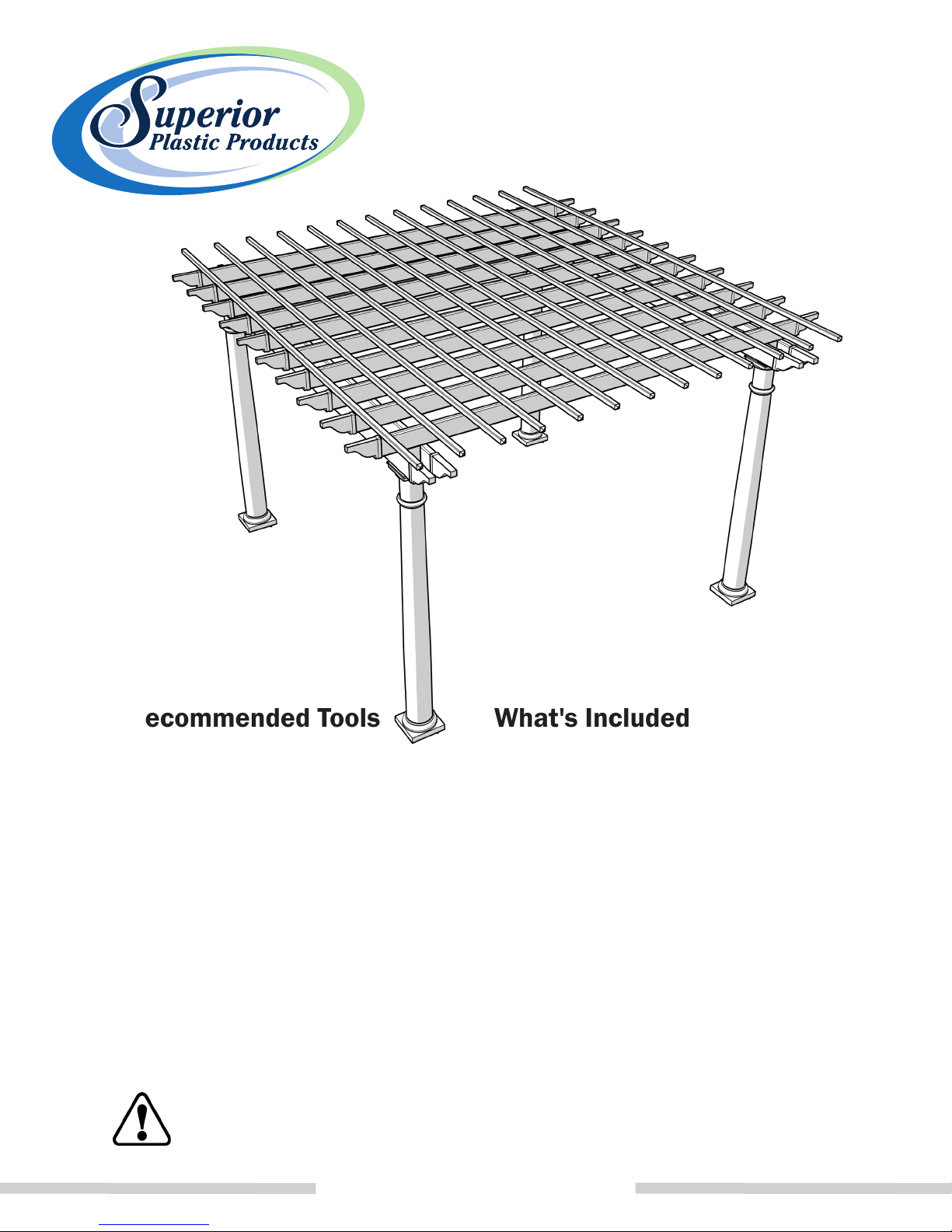
VINYL PERGOLA
SuperiorPlasticProducts.com
Recommended Tools
• Safety Glasses
• Tape Measure & Level
• Power Drill w/ (1/8" , 1/4 " , 5/8" ) bits
• Hammer Drill w/ (1/8") bit
• Circular Saw w/ Fine Tooth Blade
• Rubber Mallet
• Ladder
• These directions are only a guide and may not address every situation.
• Always wear proper safety equipment while assembling and installing.
• The installer should obtain all required building permits and follow all installation procedures in accordance
with applicable building code requirements.
• Superior Plastic Products, Inc. shall not be held liable for improper or unsafe installations.
• Applying paint, will void your warranty.
• To ensure proper coverage by our warranty please visit our website and complete the warranty form and mail
to: Superior Plastic Products, Inc., 260 Jalyn Drive, New Holland, PA 17557
WARNING: This product can expose you to chemicals including Quartz (crystalline silica), which is known to
the State of California to cause cancer, and Hexavalent Chromium, which is known to the State of California to
cause birth defects or other reproductive harm. For more information go to www.P65Warnings.ca.gov.
SuperiorPlasticProducts.com
What's Included
• Vinyl Columns
• Column Mounts w/ Leveling Plates
• Vinyl Beams w/ Aluminum Channels
• Beam Mounts
• Rafters
• Vinyl Trim sets
• All fastening hardware except concrete
bolts/ screws (sold separately)
SPPIG180928
1
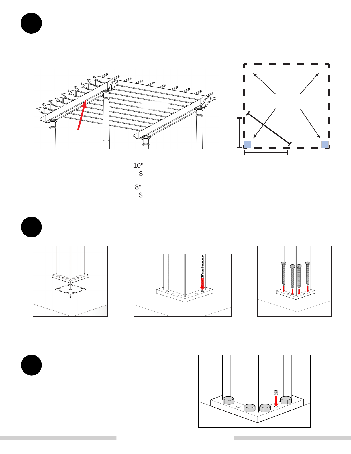
Column Placement
Using the measurements below, mark an outline
for the column mounts. If there are more than
four columns, be sure to space them evenly.
Beam
10" Tapered & 8" Straight* Column
Subtract 15 3/4" from beam length
8" Tapered & 6" Straight* Column
Subtract 13 3/4" from beam length
Rafter
3'
10" Tapered & 8" Straight* Column
Subtract 15" from rafter length
8" Tapered & 6" Straight* Column
Subtract 13" from rafter length
Post Mounts
5'
4'
Use the 3'- 4'- 5' rule, as
shown, to ensure square.
*Straight includes both square and round columns
2
Fasten Standard Column Mount
Set the Leveling Plate and Column Mount in position. Mark the hole locations,
and drill holes into the concrete.
Recommend: Use 1/2" x 5" 300-series SS or hot-dipped Galvanized bolts.
3
Level Column Mount
Using a level, ensure the Column Mount
is plumb using the adjustment screws.
SuperiorPlasticProducts.com
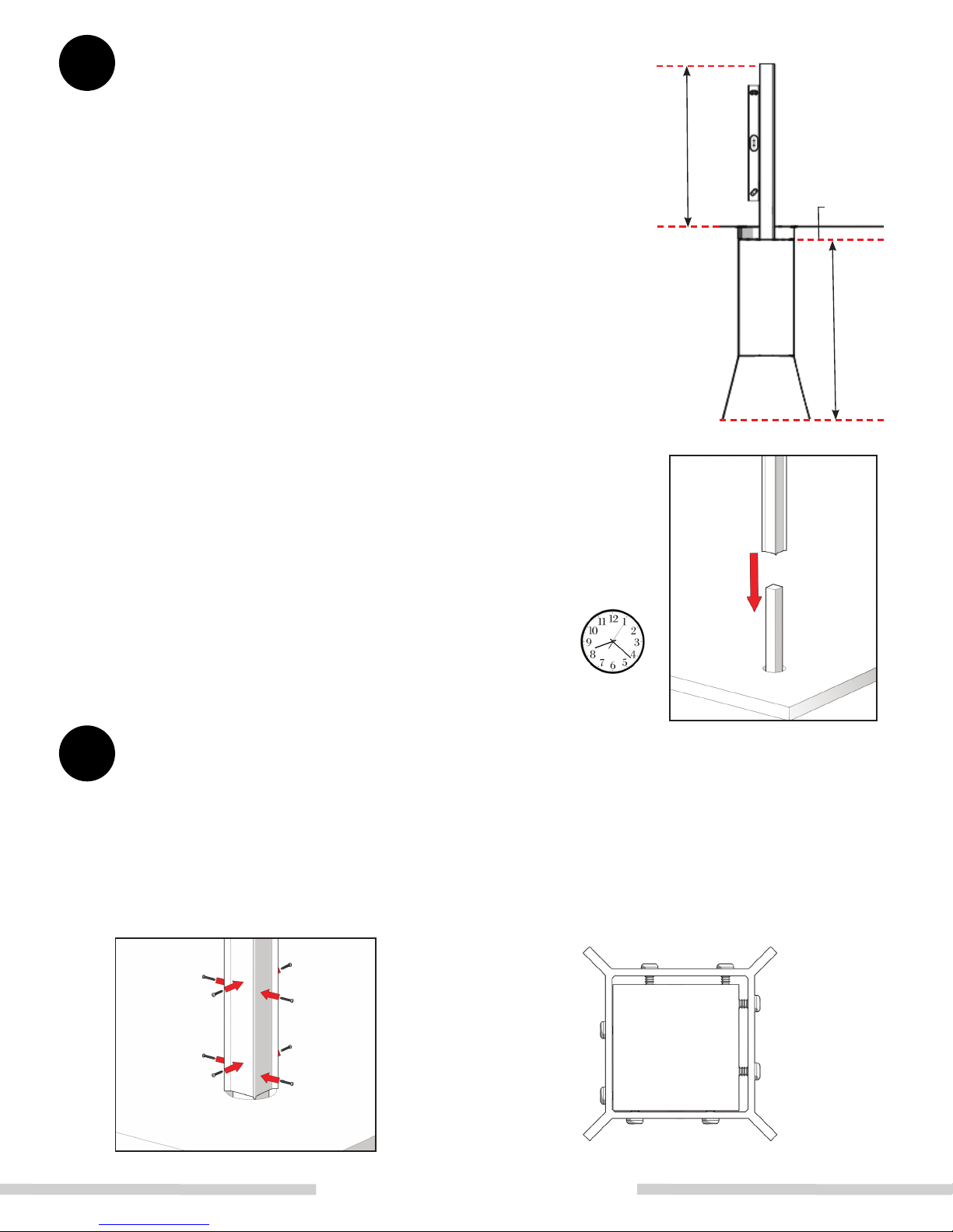
ALT
Place Concrete Column Mount
Note: We recommend a 4'' x 4'' x 54'' Pressure treated
wood Post should be used for the following steps.
Dig 9" diameter holes at each marked position. A
proper depth should allow the bottom of the hole to
fall beneath the frost line (recommended 30"). Bell
out bottom of holes to help prevent frost uplift.
To ensure proper Post depth Fill the hole with
approximately half the recommended concrete, then
& Level
Adjust Height
2" Dirt
place the Post. Measure height of Post, and adjust
to correctness (Recommended 24'' above ground).
Check and adjust level. Fill remaining space around
the Post with concrete until approximately 2" remains.
Move on to the next Post, and repeat process.
Once all Posts have been installed, double check each
Post for correct level and height. Adjust as necessary.
Note: Concrete must be allowed to fully cure
prior to installing fencing sections. (Refer to
manufacturer recommendations)
ALT
Fasten Concrete Column Mount
Wait to fully
Cure
Fasten the outward facing sides rst; which should then butt up against the
28" Concrete
4'' x 4'' Post in the corner.
Stagger screws so that they are not aligned with one another, thus covering
more surface area of the Column.
SuperiorPlasticProducts.com
Use #14 x 2''
Wood Screws
(not provided)
 Loading...